
 Submit a Paper
 Propose a Special lssue
 Open Access
ARTICLE

Numerical Simulation of Damage Behavior in Graphene-Reinforced Aluminum Matrix Composite Armatures under Multi-Physical Field Coupling
School of Materials Science and Engineering, Shenyang Ligong University, Shenyang, 110159, China
* Corresponding Author: Xiaoming Du. Email:
Computers, Materials & Continua 2026, 86(2), 1-20. https://doi.org/10.32604/cmc.2025.073285
Received 15 September 2025; Accepted 23 October 2025; Issue published 09 December 2025
 View Full Text
 Download PDF
Abstract
With the rapid advancement of electromagnetic launch technology, enhancing the structural stability and thermal resistance of armatures has become essential for improving the overall efficiency and reliability of railgun systems. Traditional aluminum alloy armatures often suffer from severe ablation, deformation, and uneven current distribution under high pulsed currents, which limit their performance and service life. To address these challenges, this study employs the Johnson–Cook constitutive model and the finite element method to develop armature models of aluminum matrix composites with varying heterogeneous graphene volume fractions. The temperature, stress, and strain of the armatures during operation were analyzed to investigate the effects of different graphene volume fractions on the deformation and damage behavior of aluminum matrix composite armatures under the multi-field coupling of electromagnetic, thermal, and structural interactions. The results indicate that, compared to the 6061 aluminum alloy matrix, the graphene-reinforced aluminum matrix composite armature significantly suppresses ablation damage at the tail and throat edges. The incorporation of graphene notably reduces the temperature rise during the armature emission process, increases the muzzle velocity under identical current excitation, and mitigates directional deformation of the armature. The 1 wt.% graphene-reinforced aluminum matrix composite armature demonstrates better agreement with experimental results at a strain rate of 2000 s−1, while simultaneously improving stress-strain response, reducing temperature rise, and improving velocity performance.Keywords
The electromagnetic railgun is an innovative weapon that utilizes electromagnetic force to launch an armature at ultra-high speeds exceeding 2 km/s from the muzzle. It offers significant technical advantages, including high initial velocity, strong lethality, and excellent controllability, thereby presenting broad application prospects in the military field [1–3]. However, during the railgun firing process, mega-ampere-level currents must pass through the system within an extremely short time frame (on the order of milliseconds). The resulting instantaneous strong magnetic field causes intense interference to both the railgun and its surroundings. Additionally, the moving armature generates Joule heat due to the pulsed current, which can lead to armature failure under the combined effects of mechanical force and thermal stress. Currently, armatures used in electromagnetic railgun firing are typically made from low-density 6-series aluminum alloys. However, traditional 6-series aluminum alloys exhibit suboptimal electrical conductivity and contain numerous precipitates with varying thermal stability phases, which can result in the loss of strengthening effects in the armature as the temperature rises during firing.
Many scholars have conducted extensive research on railguns. An et al. [4] calculated the inductance coefficients without the armature and the propulsion inductance gradient separately in both the frequency and time domains using a two-dimensional finite element method. They also computed the current distribution during armature movement through three-dimensional transient finite element analysis. Their results showed that a C-shaped aluminum armature firing on a steel rail with a resistive coating at speeds greater than 2 km/s does not produce plasma arcing; however, simulations on copper rails did exhibit plasma arcing. Subsequently, the two inductance gradients obtained from the analysis were used in circuit simulations and compared with experimental results, revealing good agreement. Tosun et al. [5] found that geometric simplifications in two-dimensional models tend to overestimate the velocity skin effect (VSE) resistance. To balance simulation accuracy and complexity, they proposed a novel quasi-transient 3D finite element model that simulates the high-speed movement of the armature during firing by varying the conductivity in the air-armature region. The results indicated that the two-dimensional VSE resistance was overestimated by approximately 40%. Furthermore, the simulation results were compared with experimental data from different electromagnetic launcher (EML) configurations, including the Y-direction electromagnetic force on rail 1 (EMFY-1) and rail 2 (EMFY-2) setups, showing good consistency. However, neither study extended their research to fully three-dimensional models beyond the two-dimensional framework.
Wu et al. [6] developed a high-current, high-strain-rate tensile testing platform to simulate the service conditions of pure copper rails in electromagnetic railguns, revealing microstructural refinement and hardness increase under extreme conditions. Zhang and Mang [7] established a transient 3D electromagnetic–thermal–structural coupled model in LS-DYNA for composite fiber-wound railguns, demonstrating that prestress effectively suppresses vibration and resonance while enhancing structural stability. Pei et al. [8] used COMSOL multiphysics simulations and theoretical modeling to study integrated projectiles, showing velocity-dependent acceleration and a pronounced skin effect in current distribution.
The literature reviewed above primarily focuses on using copper, aluminum alloys, and similar materials as armatures for research, without adequately considering the influence of the material itself on the armature’s emission performance. Aluminum-based composites exhibit excellent mechanical and physical properties, including low density, high electrical conductivity, high thermal conductivity, and resistance to wear and heat. Recent experimental studies [9–11] have demonstrated that uniformly incorporating a low volume fraction of graphene—such as graphene nanosheets, reduced graphene oxide, or graphene-coated aluminum powder—into an aluminum matrix typically leads to simultaneous improvements in thermal conductivity, electrical conductivity, and mechanical properties. Graphene-reinforced aluminum matrix composites offer significant advantages in thermal conductivity, short-term heat resistance, and mechanical strength and hardness. When good dispersion and high-quality interfaces are achieved (for example, through surface modification or heat treatment), graphene-reinforced aluminum matrix composites can effectively reduce localized Joule heating, suppress melting and ablation, and enhance wear resistance and load-bearing capacity under high-power and high-speed sliding conditions, such as those encountered in electromagnetic railgun armatures [12,13]. This is expected to become a reliable solution for armature material failures in electromagnetic emission applications [14,15].
There is limited research on the application of aluminum matrix composites in the armatures of electromagnetic emission systems. This study, based on the Johnson-Cook model, develops armature models of aluminum matrix composites reinforced with graphene at various volume fractions. The temperature, stress, and strain distributions of these heterogeneous composite armatures were simulated under the direct coupling of electromagnetic, thermal, and structural fields. This electromagnetic–thermal–structural coupling was realized in real time through a partitioned alternating mode using the same solver and implemented via the finite element method. The deformation behavior and damage mechanisms of graphene-reinforced aluminum matrix composite armatures under multi-physical field coupling effects are explained.
To accurately describe the multi-physical field coupling behavior of armature in an electromagnetic railgun during the firing process, it is essential to establish a theoretical calculation model that incorporates the electromagnetic, thermal, and structural fields [16]. This model can not only characterize the distribution of electromagnetic forces and Joule heating effects under current excitation but also capture the dynamic mechanical response of materials to thermal stress and high-strain rate conditions.
2.1 Electromagnetic Field Control Equations
The electromagnetic field is described by Maxwell’s equations [17,18]. Their differential form is:
where E is the electric field intensity, H is the magnetic field intensity, D is the electric displacement vector, B is the magnetic flux density, J is the current density, and
In conductive materials, the current density and the electric field are related by Ohm’s law:
where
This force is the primary driving force of the armature.
2.2 Temperature Field Control Equation
Joule heating in the electromagnetic field acts as a heat source term, and the temperature distribution is described by the heat conduction equation [19]:
where
This equation illustrates the mechanism by which current excitation induces a temperature rise, consequently affecting the mechanical properties of the armature material.
2.3 Structural Field Control Equation
The structural field is described by the momentum balance equation [20]:
where
2.4 Johnson-Cook Constitutive Model
Considering that the armature material of the electromagnetic railgun is subjected to high strain rates, large deformations, and elevated temperatures during the firing process, the Johnson-Cook (JC) constitutive model is selected to describe its dynamic mechanical behaviors. The JC model is expressed as follows [21]:
where
The Johnson-Cook (JC) model effectively captures the material’s strain hardening, strain rate sensitivity, and thermal softening effects, making it well-suited for describing the complex mechanical behavior of the armature under high-speed sliding and intense current conditions [22]. This theoretical framework enables the coupling of electromagnetic, thermal, and structural fields. The electromagnetic field governs electromagnetic forces and Joule heating; the thermal field addresses heat conduction and temperature rise; the structural field represents the material’s dynamic response; and the JC model accurately characterizes the constitutive behavior under high strain rates and elevated temperatures. This integrated approach provides a robust theoretical foundation for simulating and experimentally validating the railgun firing process.
2.5 Finite Element Model and Parameters
Based on a theoretical computational model, a three-dimensional representation of an electromagnetic railgun can be constructed. The launching system primarily consists of the rails, the armature, the excitation power supply system, and the launch control system. To facilitate the simulation of the motion of the armature during the launch process, complex components such as the excitation power supply system and the launch control system are omitted, and only a 3D model of the armature and rails is developed. The rails measure 3100 mm in length, 50 mm in width, and 15 mm in height, and are made of copper alloy. The armature measures 66 mm in length, 30 mm in width, and 40 mm in height, and is composed of a graphene-reinforced aluminum matrix composite material. In the simulation, flaky graphene structures of varying sizes were constructed to represent different graphene contents equivalently. It was assumed that the graphene orientation was 90°, with a random distribution of the flakes, thereby completing the modeling of the heterogeneous graphene-reinforced aluminum matrix composite armature. To minimize the impact of boundary condition constraints on the armature’s motion, the rail width is increased, and a structured mesh is applied to both the rails and the armature. The mesh size is 7 mm for the rails, 3 mm for the armature matrix, and 2 mm for the graphene-reinforced phase. To ensure simulation accuracy of the graphene-reinforced phase, two layers of mesh elements are applied in the thickness direction. Thus, the construction of the finite element model’s structured mesh is completed. The finite element method (FEM) employed in this study directly couples electromagnetic, thermal, and structural fields within a unified numerical framework. This capability is essential for accurately capturing the dynamic evolution of current density, Joule heating, and Lorentz force under millisecond-scale, high-current excitation. FEM enables the simultaneous solution of multi-field coupling problems while maintaining clear physical consistency and stable time integration. Compared to alternative numerical schemes such as the Nodal Optimization Method (NOM) [23] and the Coupled Potential Method (CPM) [24], FEM provides a more practical and physically interpretable framework for strongly coupled transient multiphysics systems, where boundary conditions and field interactions are complex. Although machine-learning-based approaches like the Deep Energy Method (DEM) [25] offer advantages in variational consistency and data-driven learning, they are better suited for static or quasi-static problems and require extensive datasets, making them unsuitable for real-time, high-strain-rate simulations. Nevertheless, FEM has certain limitations, including reduced flexibility in modeling crack propagation, smaller allowable time steps, and higher computational costs. Despite these drawbacks, it remains the most reliable and physically grounded approach for current multi-field coupling analyses, ensuring computational efficiency and numerical stability. Tables 1 and 2 present the material parameters of each component and the Johnson-Cook (J-C) material constitutive parameters, respectively. Figs. 1 and 2 illustrate the finite element model of the pivot rail and the current excitation curve, respectively. According to references [26], applying a trapezoidal current load can mitigate sudden current fluctuations, reduce impact oscillations at the electrothermal contact interface, and more accurately replicate the experimental pulse power supply. The total current duration is 4 ms, the initial temperature of the pivot rail model is 22°C, the static friction coefficient between pivot rails is 0.15, and the dynamic friction coefficient is 0.1. The emission environment is assumed to be adiabatic, with nonlinear material behavior and factors such as gravity neglected.
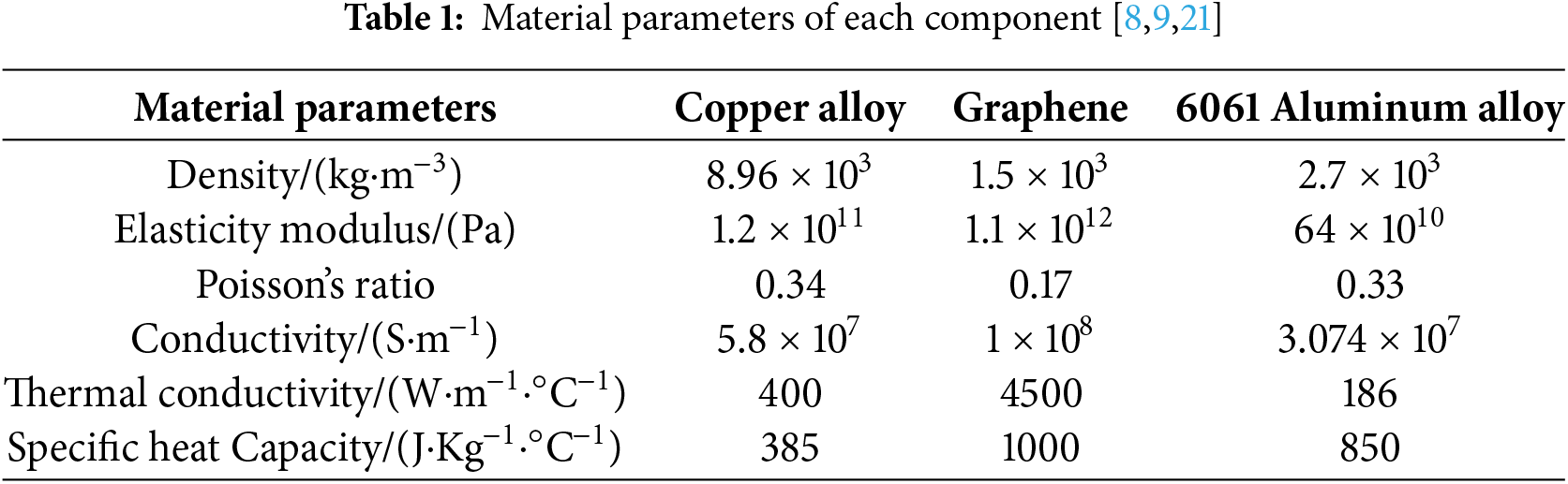
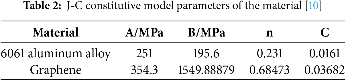
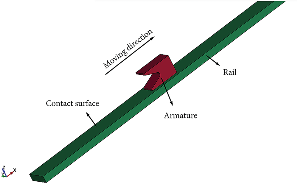
Figure 1: Finite element model of the electromagnetic armature and guide rail
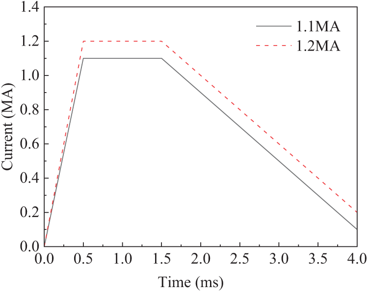
Figure 2: Current excitation curve
3.1 Electromagnetic Field Simulation Results
In an electromagnetic railgun system, the electromagnetic field is the fundamental physical field that drives the armature’s movement, and its distribution directly determines both the magnitude and spatial characteristics of the electromagnetic force acting on the armature [27]. The current forms a closed loop through the rails and the armature, while the pulsed current generates a strong magnetic field in the rails and interacts with the current in the armature (Eqs. (1) and (2)), thereby producing the Lorentz force that propels the armature at high speed (Eq. (6)). Simultaneously, the non-uniform distribution of the electromagnetic field leads to concentrated current density and localized enhancement of magnetic induction intensity, resulting in an uneven distribution of electromagnetic force. This not only reduces the system’s firing efficiency but may also accelerate wear and damage to the armature and rails. Therefore, electromagnetic field analysis is essential for conducting multiphysics coupling studies that involve thermal and structural fields.
Fig. 3 illustrates the distribution of electromagnetic force at the muzzle (2.5 ms) of the 6061 aluminum alloy armature under current excitation. As shown in Fig. 3a, the electromagnetic force is primarily concentrated at the rear end of the armature, particularly along the tail edges and throat area. This concentration occurs because, during current flow, the velocity skin effect and edge effect cause the current to concentrate mainly on the inner surface of the saddle, resulting in a localized increase in both current density and magnetic induction intensity. The accumulation of these effects at the edges and throat leads to an elevated electromagnetic force in these regions. Furthermore, in the closed circuit, the current follows the path of least resistance, with the main current flow occurring at the contact surface between the armature rail and its rear end. Consequently, the current distribution at the front part of the armature is minimal, resulting in a reduced electromagnetic force in that area. Due to these factors, the uneven current distribution causes the electromagnetic force on the armature to exhibit a gradient distribution. This pattern of electromagnetic force distribution closely aligns with the trends reported in references [28,29].
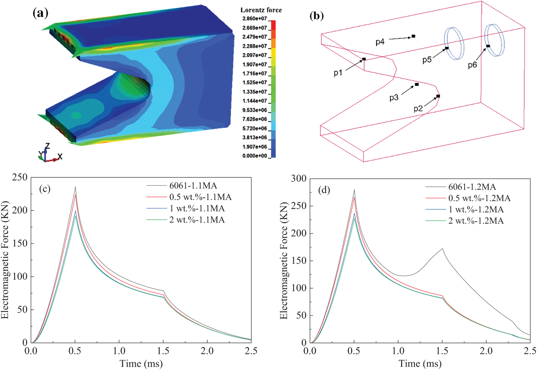
Figure 3: Electromagnetic force acting on the armature housing: (a) Electromagnetic force distribution map of the armature at the gun barrel position; (b) Diagram showing measurement points on the armature; (c) Electromagnetic force at the armature throat under a 1.1 MA current; (d) Electromagnetic force at the armature throat under a 1.2 MA current
Fig. 3c,d illustrates the electromagnetic force curves over time at the throat edge (p2 in Fig. 3b) of the armature, composed of 6061 aluminum alloy and graphene-reinforced aluminum matrix composite, respectively, under varying current amplitudes. As shown in Fig. 3c, regardless of whether the material is 6061 aluminum alloy or graphene-reinforced aluminum matrix composite, the electromagnetic force follows a similar trend: during the initial current phase (0–0.5 ms), the instantaneous increase in current causes a sharp rise in electromagnetic force, reaching its maximum at the moment the armature begins to move (0.5 ms). During the current peak phase (0.5–1.5 ms) and the current falling edge (after 1.5 ms), the electromagnetic force decreases in a nonlinear manner. This behavior results from the continuously accelerating front end of the armature experiencing magnetic diffusion effects, which reduce the current in that region and lead to a decrease in the inductance gradient. Simultaneously, deteriorating contact conditions at the armature-rail interface and the rise in temperature cause an increase in the armature’s internal resistance, resulting in energy loss within the armature and uneven current distribution. These factors weaken the actual electromagnetic force generated, causing it to peak and then decline. Notably, under the same current excitation, as the graphene content increases, the electromagnetic force at the throat edge (p2 in Fig. 3b) of the armature decreases. This reduction lessens the load impact on the armature throat, resulting in a more uniform stress distribution and less deformation, which helps extend the armature’s service life. Comparing Fig. 3c,d, it is evident that as the current excitation increases, the current density inside the armature also rises, and this increase in current density correspondingly enhances the electromagnetic force acting on the armature. However, the electromagnetic force trend reveals that increasing current excitation causes a secondary peak phenomenon in the 6061 aluminum alloy armature (at 1.5 ms), whereas the addition of graphene significantly mitigates the electromagnetic force on the armature and largely suppresses this secondary peak. This phenomenon occurs because the strong current leads to Joule heating accumulation in the throat, reducing the conductivity of the 6061 aluminum alloy armature and causing thermal softening, which results in contraction of the throat area. The increased current per unit area induces secondary current concentration, generating the secondary peak in electromagnetic force. In contrast, the graphene-reinforced aluminum-based composite armature exhibits better thermal conductivity and a lower temperature rise, which weakens material softening and geometric contraction of the armature itself, stabilizing the current per unit area and thereby suppressing the formation of the secondary peak. Therefore, while increasing current density raises the electromagnetic force at the throat, increasing the graphene content not only reduces the electromagnetic force at the throat edge but also smooths its decline, preventing severe fluctuations caused by drops in electromagnetic force.
3.2 Electromagnetic-Thermal Field Coupling Simulation Results
When the armature moves under electromagnetic force, it generates Joule heat due to its inherent resistance, and frictional heat due to the relative sliding of the armature/rail contact surface. The continuous accumulation of this thermal effect can cause local erosion and damage to the armature, and may lead to local melting of the armature, thereby shortening its service life. Due to the extremely short time interval—only milliseconds—from launch to the projectile leaving the barrel, the heat generated by friction is relatively minimal. The primary source of heat is Joule heating caused by the body’s electrical resistance.
Fig. 4 illustrates the temperature distribution of the armature at the moment that exits the barrel (2.5 ms) under a current excitation of 1.1 MA. As shown in Fig. 4a, the temperature gradient on the armature transitions inward from the saddle-shaped throat surface and the contact surface, exhibiting a gradual decrease in temperature. This occurs because, under the influence of the skin effect and the proximity effect of the excitation current, the current is primarily distributed near the surface region of the armature. The high-temperature regions are primarily concentrated at the tail and throat of the armature, particularly near the edges of the contact surface at the tail, where the temperature reaches its peak. In contrast, there is no significant temperature increase occurs at the armature head. This is due to the current flow in the armature following the shortest path principle and the skin effect, which causes the current to concentrate on the surface and edges, resulting in a higher current density. Additionally, the electromagnetic field gradient is greater at the edges, resulting in significantly higher temperatures in the tail edge region of the armature compared to other areas. Consequently, the tail of the armature reaches its melting point during firing, which exacerbates the melting of the armature. This phenomenon corresponds with the aluminum liquid melt layer left on the rail by the armature sliding over it, as reported in references [30]. Comparing the temperature distributions of different armatures in Fig. 4, it is evident that the 6061 aluminum alloy armature tail fin experiences the highest temperature and the most severe ablation. With the addition of graphene, the temperature gradient distribution at the armature throat becomes more uniform, the peak temperature at the edges decreases, and edge ablation is significantly reduced. The armature reinforced with 0.5 wt.% graphene in an aluminum matrix composite exhibits the greatest reduction in peak temperature and a smaller area of localized high-temperature regions, indicating that a small amount of graphene enhances the armature’s thermal conductivity, facilitating faster heat dissipation. The 1 wt.% graphene-reinforced aluminum matrix composite armature has a peak temperature similar to that of the 0.5 wt.% graphene composite, but the temperature distribution along the edges is significantly improved, and edge ablation is mitigated. This suggests that increasing the graphene content further enhances the armature’s heat conduction and dissipation capabilities. However, the 2 wt.% graphene-reinforced aluminum matrix composite armature shows an increase in peak temperature and an expansion of the high-temperature area, indicating that excessive graphene may cause poor interfacial bonding or graphene agglomeration, which reduces thermal conductivity and diminishes the beneficial effect. Overall, the 1 wt.% graphene-reinforced aluminum matrix composite armature outperforms both the 0.5 wt.% and 2 wt.% graphene composites in lowering the temperature of high-temperature regions and improving the uniformity of heat distribution.
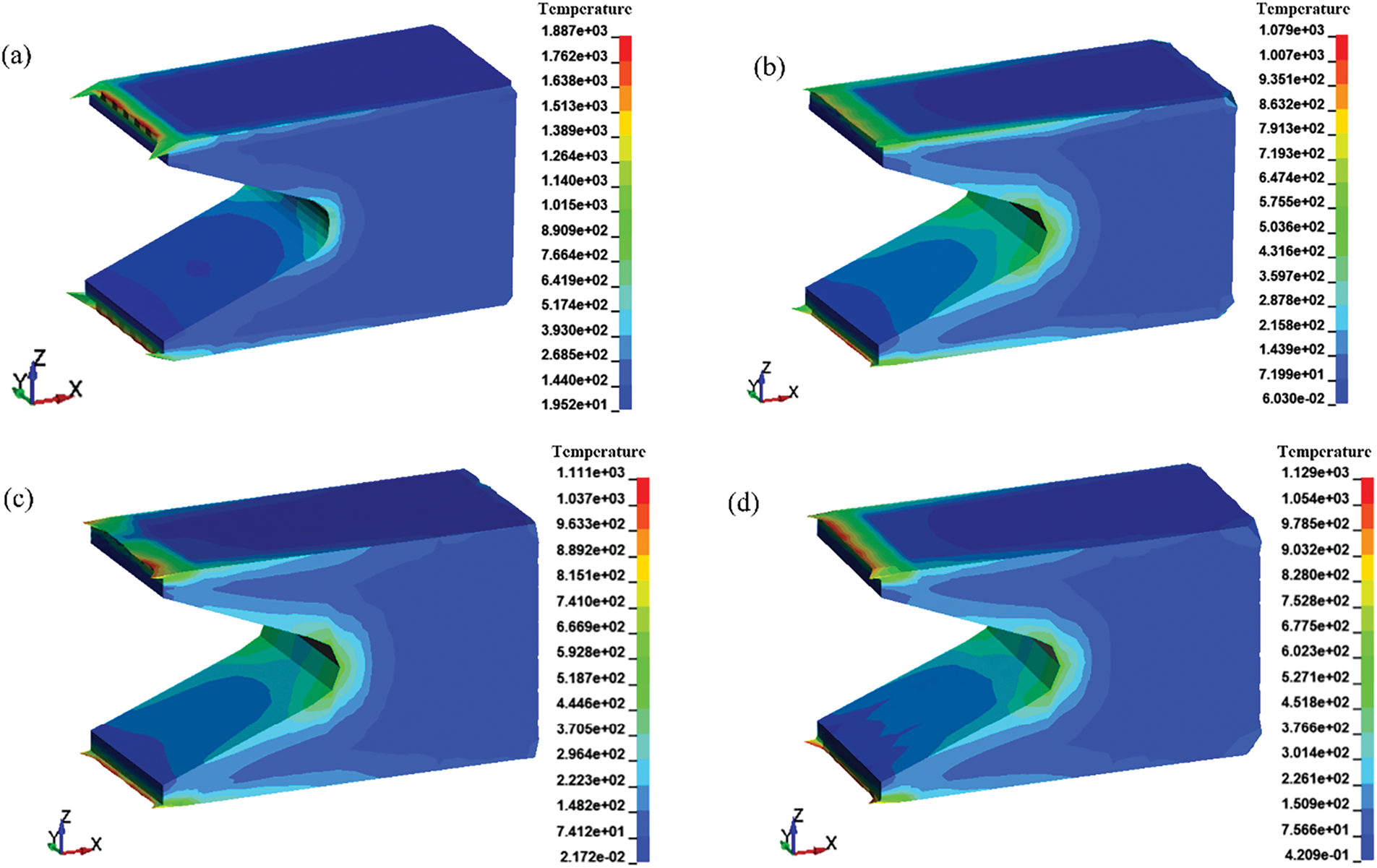
Figure 4: Temperature distribution at the outlet of different armatures (2.5 ms): (a) 6061 aluminum alloy armature; (b) 0.5 wt.% graphene aluminum-based composite armature; (c) 1 wt.% graphene aluminum-based composite armature; (d) 2 wt.% graphene aluminum-based composite armature
Fig. 5 shows the temperature distribution in different regions of the armature. As shown in Fig. 5a, the temperature of the 6061 aluminum alloy armature continuously increases under pulsed current excitation, particularly at the tail and throat regions. Before 0.5 ms of firing time, the current rises sharply. This occurs because the resistance of the armature body generates a significant amount of Joule heat in a short period, and the heat does not have sufficient time to dissipate. As a result, the armature temperature increases linearly, reaching approximately 300°C at the throat. From 0.5 to 1.5 ms of firing time, the current remains at a plateau peak stage (see Fig. 2). During this period, the internal heat generation of the armature stabilizes compared to the initial phase, and the difference between the heat generation rate and heat dissipation rate gradually decreases, resulting in a slower temperature rise. By the end of the current plateau, the surface temperature at the tail of the armature approaches nearly 800°C. After 1.5 ms of firing time, the current begins to decrease; however, heat generation still exceeds heat dissipation, causing the armature temperature to continue rising. Consequently, the tail temperature reaches its maximum near the muzzle (2.5 ms), with a peak temperature close to 1200°C. As the armature exits the muzzle, heat dissipation gradually surpasses heat generation, leading to an overall decrease in armature temperature.
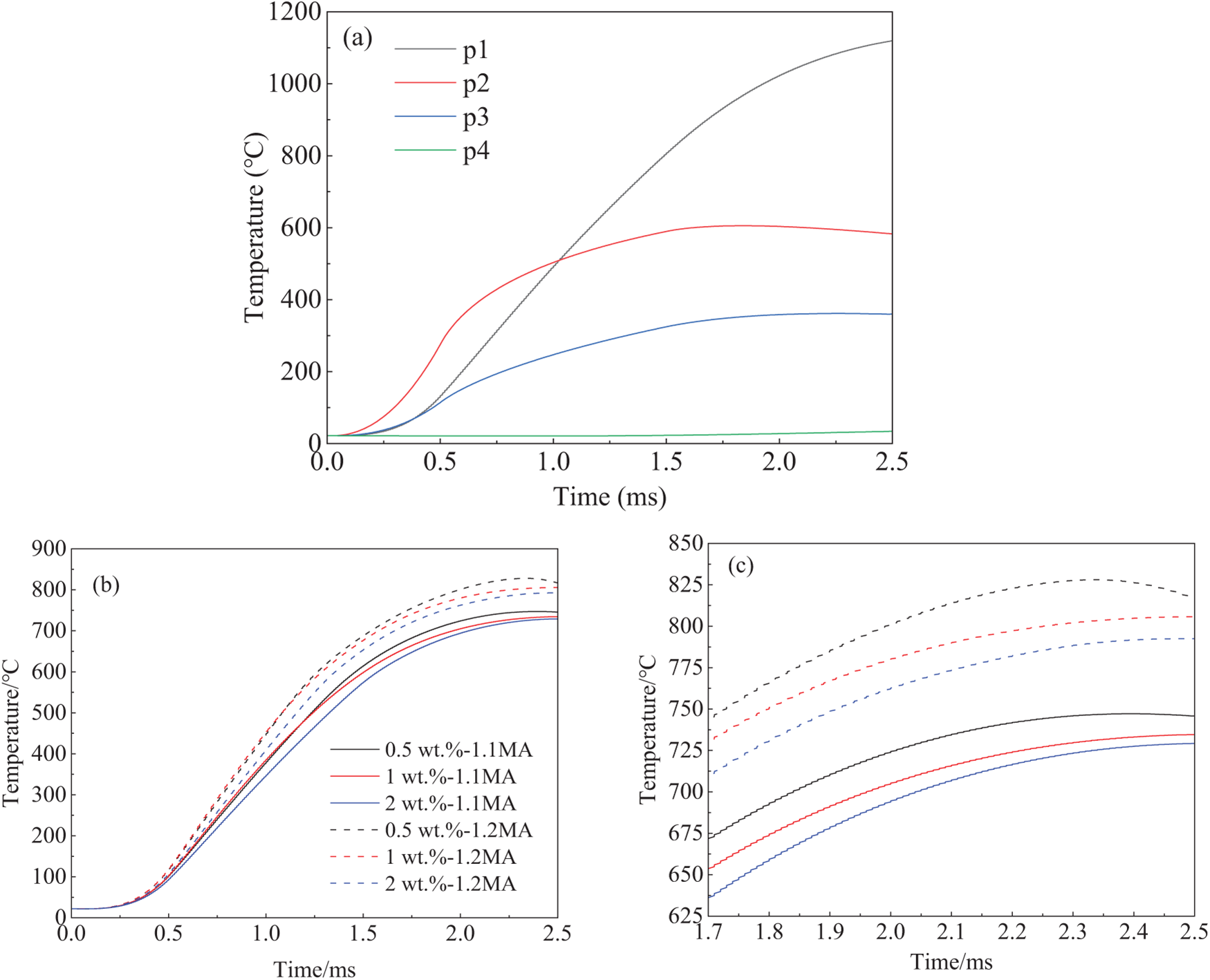
Figure 5: Temperature comparison curves of the armature: (a) Temperature curves at different points on the 6061 aluminum alloy armature; (b) Comparison of temperatures of various graphene-reinforced aluminum-based composite armatures; (c) Partial temperature magnification of Fig. 5b
To investigate the effect of graphene on the ablation resistance of aluminum alloy armatures, three aluminum matrix composite armature models with graphene volume fractions of 0.5, 1, and 2 wt.% were developed, and electromagnetic emission simulations were performed. Fig. 5b,c presents temperature distribution curves at the tail edge (p1 in Fig. 3b) of different aluminum matrix composite armatures under various current excitations. Compared to the 6061 aluminum alloy armature, the temperature at the tail edge (p1) of aluminum matrix composite armature is significantly higher than at other points. During the armature emission process, this location experiences the fastest and continuously increasing temperature rise. This extreme temperature rise causes severe plastic deformation of the armature and extensive melting during sliding, altering the contact surface between the armature and rail. This leads to unstable contact, which easily results in arc ablation and further exacerbates poor interface contact. The addition of graphene has a particularly significant impact on temperature changes after the peak phase of the current plateau (0.5 ms). With graphene incorporation, the temperature rise of the armature during the current plateau phase is mitigated, especially during the current decline phase (1.5 ms) and near the muzzle, where the temperature increase decreases substantially. This indicates that graphene significantly enhances the armature’s ablation resistance, effectively reducing melting and ablation at the armature tail caused by high temperatures. This improvement is attributed to graphene’s extremely high thermal conductivity and carrier mobility, which maintain high electrical conductivity even at elevated temperatures, enabling rapid current conduction and heat dissipation throughout the armature in a very short time. By comparing the armature temperatures of graphene-reinforced aluminum matrix composites under different currents, it is observed that increasing the current by 0.1 MA raises the temperature at the tail of the armature by approximately 80°C. As the amplitude of the current excitation increases, the effect of graphene in reducing the temperature rise becomes progressively stronger. Therefore, comparing the temperature rise curves at the tail edge (p1) of the 6061 aluminum armature and the graphene-reinforced aluminum matrix composite armatures with varying graphene content demonstrates that adding graphene improves thermal conductivity of armatures and significantly reduces temperature rise in armatures.
3.3 Electromagnetic-Thermal-Structural Field Coupling Simulation Results
3.3.1 Analysis of Armature Deformation
The armature moves forward under the force of electromagnetic power, while the Joule heat generated by its electrical resistance increases its susceptibility to deformation due to the combined effects of electrical, thermal, and structural factors. This, in turn, exacerbates damage to the armature during motion.
Fig. 6a,b illustrates the deformation behavior of armatures made from different materials under current excitations of 1.1 and 1.2 MA in the Y and Z directions, respectively. Overall, the armature exhibits good symmetry in deformation along both directions, with the maximum deformation occurring at the rear end. However, there are significant differences in the deformation distribution between the two directions: deformation in the Y direction is primarily concentrated at the edges of the throat region, whereas deformation in the Z direction is mainly distributed around the tail fin area. This variation in distribution is closely related to the electromagnetic environment experienced by the armature. Since the current density and electromagnetic forces are predominantly concentrated on the inner side of the saddle surface, and the force direction is mainly horizontal, the throat edges and tail fin locations become critical zones for the coupled effects of electromagnetic, thermal, and mechanical fields.
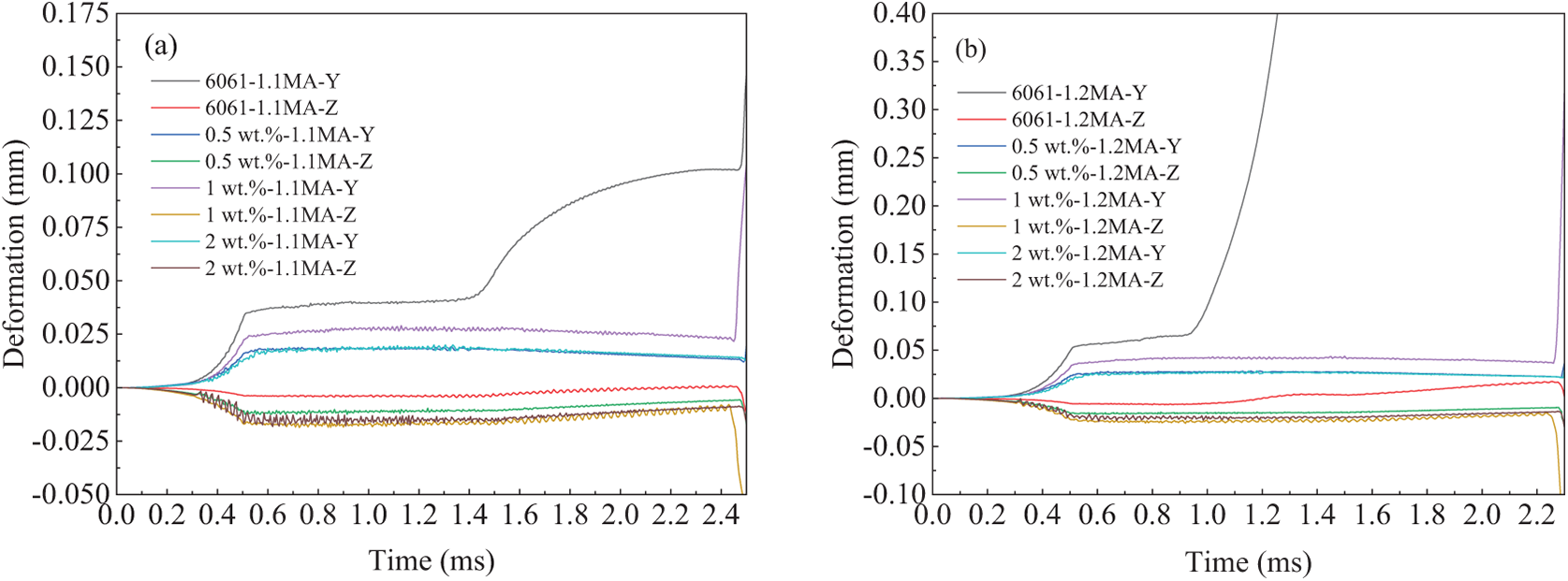
Figure 6: Comparison of deformation along the direction of different material armatures: (a) Deformation along the armature direction under a 1.1 MA current; (b) Deformation along the armature direction under a 1.2 MA current
Under strong current excitation, the damage mechanisms of the armature are highly complex. The primary forms of damage can be categorized into three types: thermal damage, arc erosion, and mechanical damage [31–33]. First, during high-speed sliding, the armature experiences intense Joule heating, resulting in localized melting and ablation of the surface material. This is accompanied by transient impacts from electric arcs, which further cause surface layer peeling and deeper damage, significantly exacerbating the armature’s thermal deformation. Second, the throat and contact interfaces, subjected to strong electromagnetic forces and inertial loads, also undergo frictional slip and uneven surface contact due to fatigue impacts under thermo-mechanical coupled cyclic loading. These factors readily induce surface wear, plastic deformation, and even morphological instability, thereby accelerating the mechanical damage progression of the armature. Under the combined effects of these three factors, the deformation amplitude of the armature in the Y-direction is significantly greater than that in the Z-direction, closely corresponding to the distribution pattern of the coupled loads it endures.
A further comparison of the deformation curves of armatures made from different materials reveals that graphene-reinforced aluminum matrix composite armatures exhibit a significant advantage in suppressing deformation. The incorporation of graphene not only enhances the mechanical properties of the material but also improves its electrothermal conductivity, resulting in a more uniform distribution of electromagnetic forces. This, in turn, substantially reduces stress concentration and deformation accumulation in the throat region. Under a 1.2 MA current excitation, this suppression effect is particularly pronounced: the deformation of the throat area in the composite armature during acceleration is greatly diminished, with the overall deformation level decreasing by more than 70% compared to the 6061 aluminum alloy armature, effectively preventing instability and failure caused by excessive deformation at the muzzle exit.
However, it should be noted that the deformation behavior of the graphene-reinforced aluminum matrix composite armature in the Z direction differs from that in the Y direction. Compared to the 6061 aluminum alloy armature, the composite armature exhibits slightly greater deformation in the Z direction. This is primarily attributed to the introduction of graphene, which enhances the armature’s electrical conductivity, resulting in a more uniform distribution of electromagnetic forces on the inner side of the throat and thereby inducing greater lateral deformation in the tail wing area. Additionally, because the graphene is randomly distributed within the armature cavity—especially concentrated in the front-end region—its local agglomeration and dispersion effects cause the differences in Z-direction deformation of the tail wing to be minimal.
3.3.2 Dynamic Damage Mechanism
To investigate the deformation and damage behavior of the armature under the combined effects of multiple fields during electromagnetic railgun firing, a coupled electromagnetic-thermal-structural simulation of the electromagnetic railgun was performed. Fig. 7 illustrates the stress distribution in armatures made from four different materials at 2.5 ms, the moment the armature leaves the rail.
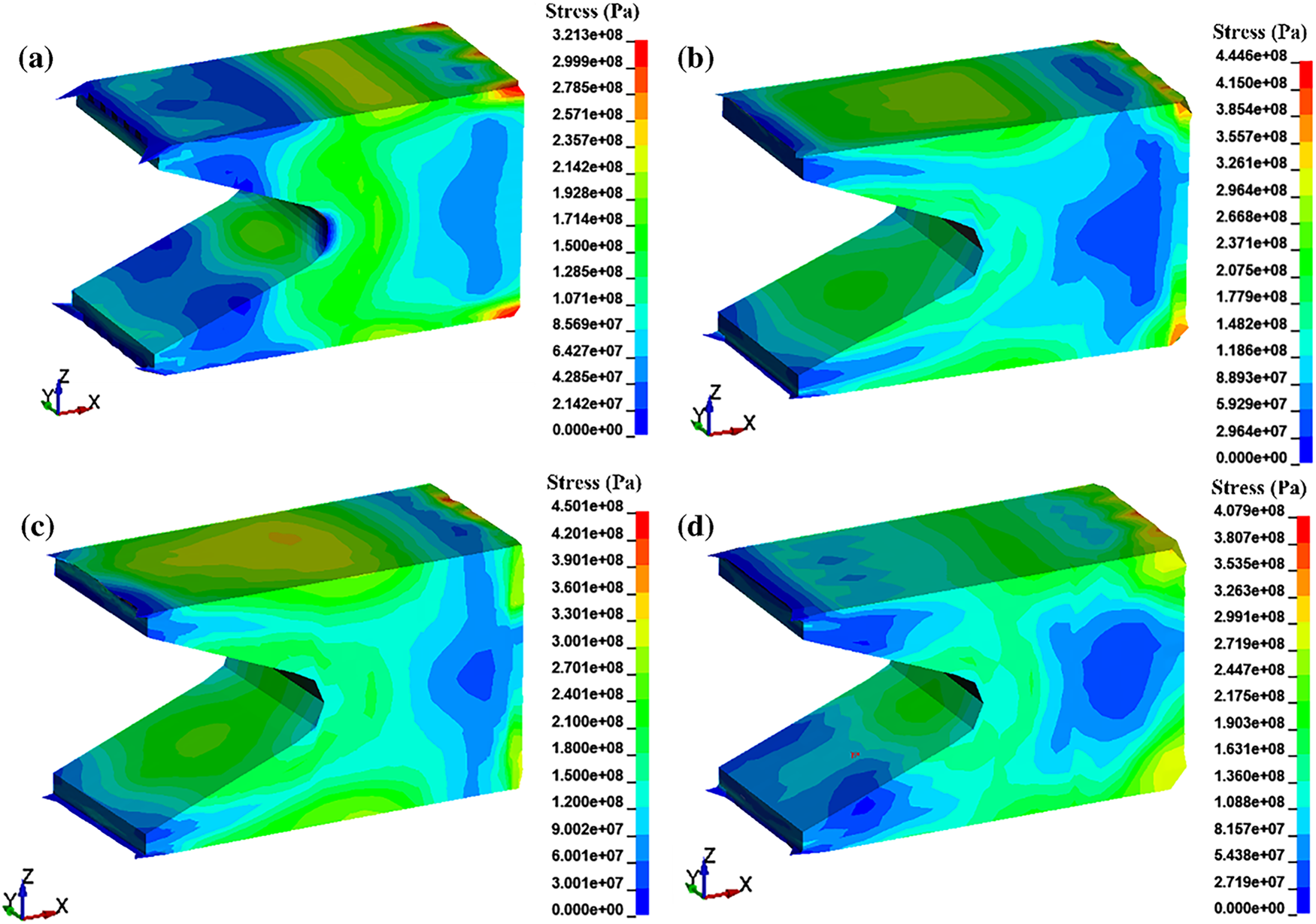
Figure 7: Stress distribution on the armature at 2.5 ms: (a) 6061 aluminum alloy armature; (b) 0.5 wt.% graphene volume fraction/6061 aluminum composite material; (c) 1 wt.% graphene volume fraction/6061 aluminum composite material; (d) 2 wt.% graphene volume fraction/6061 aluminum composite material
As shown in Fig. 7a, the maximum stress value has already exceeded the yield strength of the aluminum alloy. The stress peak occurs at the edge of the armature head, with the high-stress region primarily concentrated in the throat area on the inner side of the armature. The stress distribution, similar to the temperature distribution, decreases stepwise from the throat toward the tail, demonstrating good consistency. Fig. 7a–d also indicates that the stress at the throat decreases with the volume fraction of graphene, and the stress distribution becomes more uniform. This suggests that the addition of graphene modifies the stress transmission mechanism within the armature by partially obstructing dislocation movement and enhancing the composite material’s strength, thereby significantly reducing damage to the armature. From the magnified local micrograph of the armature in Fig. 8, it is evident that the stress on the inner side of the throat of the 6061 aluminum alloy armature (shown in Fig. 8a) has already exceeded the yield strength. This indicates that the armature gradually undergoes increasing internal stress during sliding, and by the time it approaches the muzzle, irreversible plastic deformation has occurred, resulting in severe damage to the armature. Therefore, during the electromagnetic launch process, the throat of the armature—a geometric contraction and stress concentration zone—experiences a multi-field coupling of electromagnetic forces, contact reaction forces, and thermal stresses, making it the weakest link and most susceptible to plastic flow and crack initiation. After the addition of the graphene (as shown in Fig. 8b–d), the load is initially borne by the 6061 aluminum matrix and gradually transferred to the graphene. Due to the extremely high modulus and strength of graphene, it undergoes almost no plastic deformation, exhibiting significant stress shielding and load bypass effects: the peak stress at the throat is partially “diverted” to the graphene, effectively reducing the peak stress in the matrix at the throat cross-section and thereby lowering stress concentration at the throat. Additionally, dislocations moving along the principal stress direction are strongly impeded near the interface by the graphene, causing accumulation and forming localized (controllable) stress concentrations. As a highly thermally conductive pathway, graphene not only reduces the temperature gradient at the throat caused by Joule heating and friction but also synchronously decreases thermal stress and thermal softening effects, further suppressing yielding at the throat. Comparing the three types of graphene-reinforced aluminum matrix composite armatures, it is evident that the 0.5 wt.% graphene-reinforced aluminum matrix composite armature exhibits insufficient improvement in throat stress due to the low graphene content. Conversely, during the preparation process of 2 wt.% graphene-reinforced aluminum matrix composite materials, graphene agglomeration may occur, which may cause severe stress concentration in armature emission. In this case, the agglomerated graphene behaves like a “hard tool”, causing cutting-like damage to the surrounding matrix. The interface between the graphene and the matrix is the primary site of stress concentration, which promotes the formation and gradual propagation of microcracks at the interface, triggering localized mesh failure. Meanwhile, dislocations in the matrix move along the direction of stress transfer under impact loading but are strongly impeded when they encounter graphene obstacles. This dislocation pile-up effect further intensifies stress concentration at the interface region, exacerbating local damage to the matrix surrounding the graphene. However, the 1 wt.% graphene-reinforced aluminum matrix composite armature optimizes the armature matrix more effectively. Graphene significantly alleviates peak stress and thermal softening through a threefold mechanism involving load bypassing, stress shielding, and heat diffusion. Throughout the entire armature launch process, it ensures stable contact, thermal safety, smooth dynamics, and an extended lifespan.
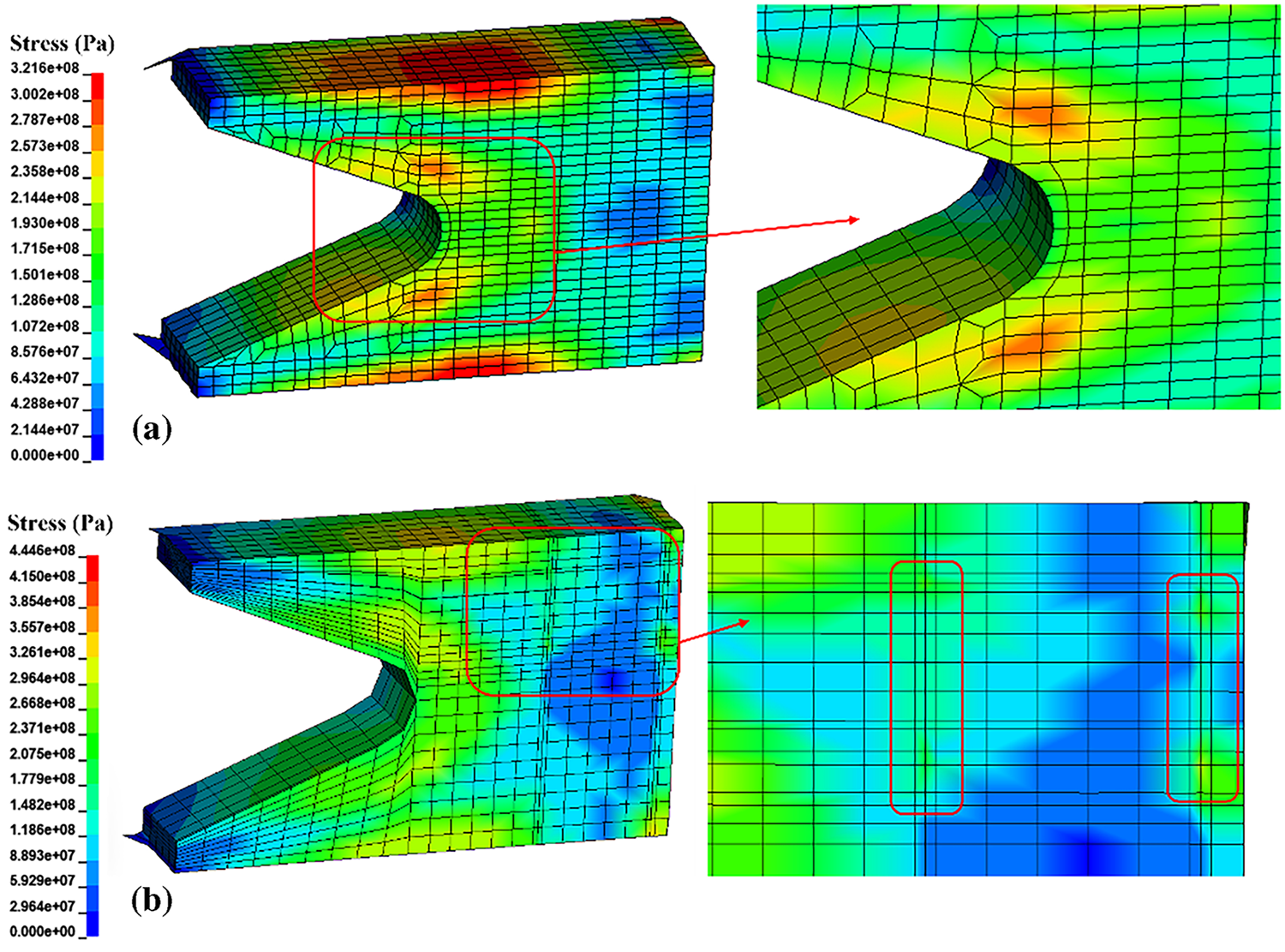
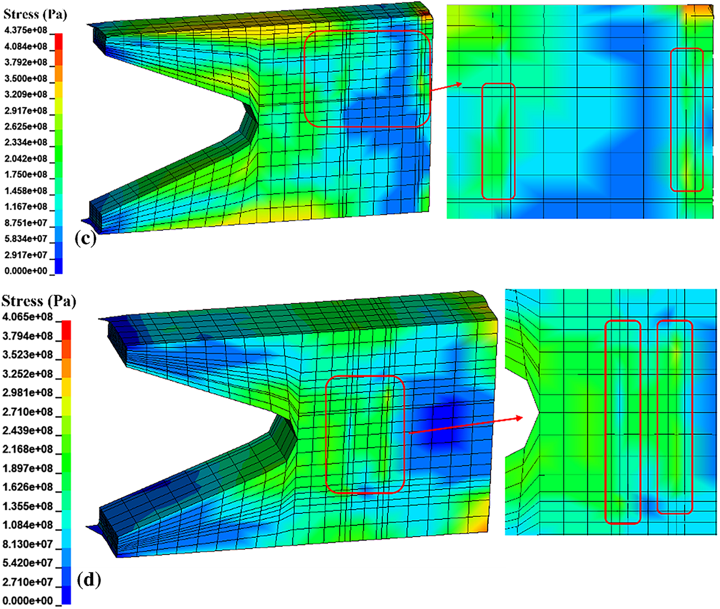
Figure 8: Microscopic cross-sectional views and partial magnifications of the armature: (a) sectional view of 6061 aluminum alloy armature; (b) cross-sectional view of 0.5 wt.% graphene-reinforced aluminum-based composite armature; (c) cross-sectional view of 1 wt.% graphene-reinforced aluminum-based composite armature; (d) cross-sectional view of 2 wt.% graphene-reinforced aluminum-based composite armature
Graphene not only exhibits ultra-high thermal conductivity but also offers excellent electrical conductivity and lightweight efficiency advantages. Under identical current excitation conditions, it can significantly increase the muzzle velocity and improve the energy conversion efficiency of electromagnetic railguns. Fig. 9 presents the velocity curves of various armature types during the electromagnetic railgun firing process, along with a comparison of stress-strain results for armatures P5 and P6, including experimental data.
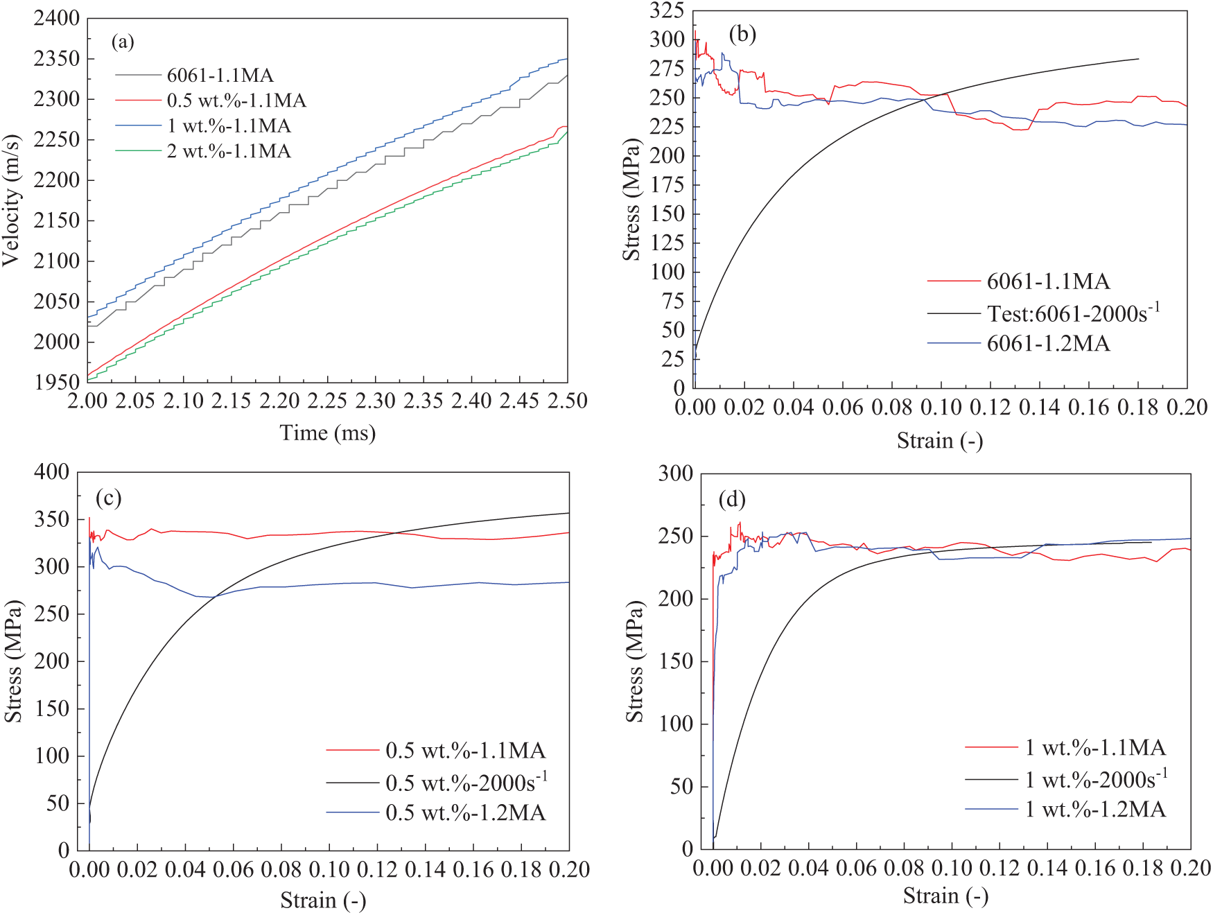
Figure 9: Speed curves of the armature at point P1 and stress-strain results compared with experimental data: (a) speed curves of aluminum-based composite armatures; (b) comparison of simulation and experimental results for the 6061 aluminum alloy armature; (c) comparison of simulation and experimental results for the armature with 0.5 wt.% graphene volume fraction in 6061 aluminum composite material; (d) comparison of simulation and experimental results for the armature with 1 wt.% graphene volume fraction in 6061 aluminum composite material
As shown in Fig. 9a, the addition of graphene increases the muzzle velocity of the armature. However, for the 0.5 and 2 wt.% graphene-reinforced aluminum matrix composite armatures, the velocity decreases. This decrease is related to the quantity, location, and arrangement of the graphene in the heterogeneous model. The 0.5 wt.% graphene-reinforced aluminum matrix composite lacks sufficient reinforcement to suppress plastic deformation and wear, leading to changes in the contact type between the armature and rail. Consequently, energy is lost through plastic dissipation and contact loss, resulting in a velocity drop. In the 2 wt.% graphene-reinforced aluminum matrix composite, excessive reinforcement content causes local agglomerations inside the armature, leading to stress concentration and interface weakening. This results in energy being primarily dissipated as heat and a significant reduction in velocity. In contrast, the 1 wt.% graphene-reinforced aluminum matrix composite, containing an optimal amount of graphene, not only enhances plastic strengthening but also improves the conduction path of the armature current, resulting in a more uniform current distribution. This reduces localized Joule heating and decreases thermal softening, allowing more energy to be converted into kinetic energy and thereby increasing the armature’s muzzle velocity. As shown in Fig. 9b–d, under a strain rate of 2000 s−1, the stress-strain curves of the 6061 aluminum alloy armature during the launch process exhibit deformation characteristics similar to those observed experimentally. Overall, the simulated yield stress is higher than the experimental results during the elastic stage but slightly lower during the plastic deformation stage. This discrepancy primarily arises from the inherent simplifications of the finite element model and the complex conditions present during high-strain-rate experiments. The Johnson–Cook constitutive model used in the simulation assumes material homogeneity and isotropy under adiabatic conditions, idealizing the actual heterogeneous response of the armature during electromagnetic launch. In reality, localized plastic deformation, current concentration, and rapid temperature rise lead to nonlinear stress evolution that is challenging to fully capture within the numerical framework. At the initial launch stage, the armature is subjected to a short pulse current that induces an instantaneous high stress, reaching the yield strength of materials. As the armature moves forward and the temperature rises, thermal softening within the material alleviates stress, causing a downward trend in the simulated stress response during the plastic deformation stage. Consequently, the simulated values in the plastic region are lower than the experimental data. Additionally, unavoidable experimental uncertainties—such as equipment stability, thermal fluctuations, and variations in contact resistance between the armature and rail—can introduce disturbances that affect the consistency between simulation and experiment. Despite these discrepancies, the overall evolutionary trend of the simulated and experimental stress–strain curves remains consistent, particularly regarding yield behavior, strain hardening, and ultimate stress levels. The maximum deviation in the stress response is within 10%, which is acceptable under high-strain-rate dynamic conditions. Notably, the stress–strain curve of the 1 wt.% graphene-reinforced aluminum matrix composite armature exhibits the closest agreement between simulation and experiment, with a relative error of less than 5%. This superior consistency can be attributed to the balanced enhancement effects of graphene: a moderate graphene content effectively improves both electrical and thermal conductivity, promotes uniform current and temperature distribution, and mitigates localized softening and stress concentration during loading. Additionally, the strong interfacial bonding between graphene and the aluminum matrix enhances load transfer and stabilizes the mechanical response, enabling the model to more accurately reproduce experimental results. Both the experimental and numerical results demonstrate strong overall agreement, confirming that the established Johnson-Cook-based multi-field coupling model reliably describes the dynamic response and damage behavior of graphene-reinforced aluminum matrix composite armatures under extreme electromagnetic launch conditions.
From a comprehensive performance perspective, although the 1 wt.% graphene-reinforced aluminum matrix composite armature does not achieve the maximum suppression of deformation in the Y direction, it demonstrates the most balanced overall behavior when considering the combined effects of electromagnetic force, thermal response, and structural deformation. Specifically, this configuration exhibits an optimal equilibrium among stress distribution, strain evolution, temperature rise mitigation, and velocity response. The moderate graphene content effectively enhances the electrical and thermal conductivity of the composite, promoting a more uniform current distribution and alleviating local stress concentrations in the throat and tail regions. This results in a smoother electromagnetic force evolution and reduced thermal softening, thereby improving the mechanical stability of the armature during launch. Consequently, the appropriate incorporation of graphene not only inhibits excessive deformation under high current loading but also delays the initiation of damage and failure by improving energy conversion efficiency and suppressing localized thermal degradation. These results confirm that 1 wt.% graphene reinforcement achieves the best synergy among electrical, thermal, and mechanical performance, providing a robust foundation for optimizing composite armature design in electromagnetic launch systems.
This study employs the finite element method to develop a Johnson-Cook (J-C) constitutive material model for simulating the deformation and damage behavior of graphene-reinforced aluminum matrix composite armatures under the combined effects of electromagnetic, thermal, and structural fields. It investigates the influence of graphene volume fraction on armature damage within a heterogeneous armature model subjected to varying current amplitude excitations and presents the following key conclusions.
(1) The temperature rise in the armature tail and throat significantly decreases as the graphene volume fraction increases. Compared to the 6061 aluminum alloy, the aluminum matrix composite armature effectively suppresses ablation damage at the edges of the tail and throat.
(2) The damage to the armature is primarily concentrated on the tail fin at its rear end and the inner surface of the throat, with the most severe damage occurring near the edges. Adding 1 wt.% graphene optimally reduces the deformation and damage to the armature, whereas 0.5 and 2 wt.% graphene either offer insufficient improvement or exacerbate the deformation and damage.
(3) As the current excitation increases, the temperature-mitigating effect of graphene becomes more pronounced; however, higher currents cause greater deformation in the throat region at the muzzle exit, resulting in more severe damage to the armature.
(4) The 1 wt.% graphene-reinforced aluminum matrix armature exhibits the closest agreement with experimental results obtained at a strain rate of 2000 s−1, showing a more pronounced increase in velocity.
Acknowledgement: Not applicable.
Funding Statement: This research was funded Basic Research Projects of Higher Education Institutions in Liaoning Province (JYTZD20230004), Future Industry Frontier Technology Project in Liaoning Province in 2025 (2025JH2/101330141), and Key Research and Development Program of Liaoning Province in 2025.
Author Contributions: The authors confirm contribution to the paper as follows: Conceptualization: Xiaoming Du; Methodology: Junwen Huo, Haicheng Liang and Weiye Dong; Formal analysis: Junwen Huo and Xiaoming Du; Writing (reviewing and editing): Xiaoming Du and Junwen Huo; Project administration: Xiaoming Du and Haicheng Liang. All authors reviewed the results and approved the final version of the manuscript.
Availability of Data and Materials: The authors confirm that the data supporting the findings of this study are available within the article.
Ethics Approval: Not applicable.
Conflicts of Interest: The authors declare no conflicts of interest to report regarding the present study.
References
1. Naga Praneeth SR, Singh B. Investigations on armature jerk for different current pulse and rail geometries in an electromagnetic railgun. IEEE Trans Plasma Sci. 2024;52(4):1486–91. doi:10.1109/TPS.2024.3382003. [Google Scholar] [CrossRef]
2. Li J, Yan P, Yuan WQ. Electromagnetic gun technology and its development. High Volt Eng. 2014;40(4):1052–64. (In Chinese). doi:10.13336/j.1003-6520.hve.2014.04.014. [Google Scholar] [CrossRef]
3. Zhang B, Meng XX, Wang K, Han T. Analysis of system transient magnetic field radiative characteristics during electromagnetic railgun launch. J Gun Launch Control. 2022;43(4):33–7. (In Chinese). doi:10.19323/j.issn.1673-6524.2022.04.005. [Google Scholar] [CrossRef]
4. An S, Lee B, Bae Y, Lee YH, Kim SH. Numerical analysis on the transient inductance gradient of the resistive overlay rail on the sliding electrical contact. IEEE Trans Plasma Sci. 2019;47(5):2339–42. doi:10.1109/tps.2018.2889249. [Google Scholar] [CrossRef]
5. Tosun N, Ceylan D, Polat H, Keysan O. A comparison of velocity skin effect modeling with 2-D transient and 3-D quasi-transient finite element methods. IEEE Trans Plasma Sci. 2021;49(4):1500–7. doi:10.1109/tps.2021.3067105. [Google Scholar] [CrossRef]
6. Wu K, Wu W, Pan A, Guo C, Cui F, Yang X, et al. Investigation on the microstructure evolution and mechanical properties of electromagnetic rail material in a launch environment. Mater Charact. 2024;208(7):113582. doi:10.1016/j.matchar.2023.113582. [Google Scholar] [CrossRef]
7. Zhang Q, Mang SS. Rail structure deformation analysis of composite material barrel for electromagnetic railgun. Mech Eng. 2023;3:78–82. (In Chinese). [Google Scholar]
8. Pei CG, Liu GZ, Jin YX, Yuan ZK, Wang DW. Dynamic analysis of electromagnetically launched integrated projectiles based on COMSOL. J Gun Launch Control. 2024;45(1):104–12. (In Chinese). doi:10.19323/j.issn.1673-6524.202305005. [Google Scholar] [CrossRef]
9. Li Y, Du XM, Liu FG. Microstructure and mechanical properties of graphene-reinforced 6061 aluminum matrix composites. J Shenyang Ligong Univ. 2023;42(2):49–55. (In Chinese). [Google Scholar]
10. Shi YN, Du XM, Liu FG. Study on dynamic properties of graphene reinforced aluminum matrix composites. J Shenyang Ligong Univ. 2022;41(6):74–9. (In Chinese). [Google Scholar]
11. Cao L, Chen B, Jia ZD, Gao JL, Li JS. Research progress and aerospace applications of aluminum matrix composite. Foundry Technol. 2023;44(8):685–705. (In Chinese). doi:10.16410/j.issn1000-8365.2023.3202. [Google Scholar] [CrossRef]
12. Wang F, Liu H, Liu Z, Guo Z, Sun F. Microstructure analysis, tribological correlation properties and strengthening mechanism of graphene reinforced aluminum matrix composites. Sci Rep. 2022;12(1):9561. doi:10.1038/s41598-022-13793-y. [Google Scholar] [PubMed] [CrossRef]
13. Md Ali A, Omar MZ, Hashim H, Salleh MS, Mohamed IF. Recent development in graphene-reinforced aluminium matrix composite: a review. Rev Adv Mater Sci. 2021;60(1):801–17. doi:10.1515/rams-2021-0062. [Google Scholar] [CrossRef]
14. Li PY. Research progress in high-performance aluminum matrix composites. J Mater Eng. 2023;51(4):67–87. (In Chinese). [Google Scholar]
15. Zou X, Chen L, Wang Z, Xu X, Zhang Z. Study on melting and wear characteristics of sliding electric contact functionally gradient material armature. Trans China Electrotech Soc. 2024;39(19):5947–57. doi:10.19595/j.cnki.1000-6753.tces.231406. [Google Scholar] [CrossRef]
16. Zhang B, Kou Y, Jin K, Zheng X. A multi-field coupling model for the magnetic-thermal-structural analysis in the electromagnetic rail launch. J Magn Magn Mater. 2021;519(4):167495. doi:10.1016/j.jmmm.2020.167495. [Google Scholar] [CrossRef]
17. Yin Q, Zhang H, Li HJ, Yang YX. Analysis of in-bore magnetic field in C-shaped armature railguns. Def Technol. 2019;15(1):83–8. doi:10.1016/j.dt.2018.07.009. [Google Scholar] [CrossRef]
18. Zhang B, Jin K, Kou Y, Zheng X, Li Y. Modelling of magneto-electro-thermo-mechanical coupled behavior of the lubricating liquid film for the electromagnetic launch. Int J Heat Mass Transf. 2022;196(7):123267. doi:10.1016/j.ijheatmasstransfer.2022.123267. [Google Scholar] [CrossRef]
19. Liao G, Wang W, Xu J, Liu X, Liu K. Mechanisms of solid-liquid evolution and current-carrying characteristics at contact interface under the magneto-thermal effect. Tribol Int. 2024;198:109848. doi:10.1016/j.triboint.2024.109848. [Google Scholar] [CrossRef]
20. Zhang B, Jin K, Kou Y, Zheng X, Li Y. Modelling of magneto-electro-thermo-mechanical coupled behavior for the conductors under powerful impulse current and high-velocity friction. Comput Struct. 2022;266(4):106787. doi:10.1016/j.compstruc.2022.106787. [Google Scholar] [CrossRef]
21. Lin QH, Li BM. Numerical simulation of transient temperature field in the electromagnetic railgun. J Eng Thermophys. 2017;38(1):149–54. (In Chinese). [Google Scholar]
22. Lin QH, Li BM. Numerical simulation of dynamic large deformation and fracture damage for solid armature in electromagnetic railgun. Def Technol. 2020;16(2):348–53. doi:10.1016/j.dt.2019.05.020. [Google Scholar] [CrossRef]
23. Rabczuk T, Ren H, Zhuang X. A nonlocal operator method for partial differential equations with application to electromagnetic waveguide problem. Comput Mater Contin. 2019;59(1):31–55. doi:10.32604/cmc.2019.04567. [Google Scholar] [CrossRef]
24. Samaniego E, Anitescu C, Goswami S, Nguyen-Thanh VM, Guo H, Hamdia K, et al. An energy approach to the solution of partial differential equations in computational mechanics via machine learning: concepts, implementation and applications. Comput Meth Appl Mech Eng. 2020;362(2):112790. doi:10.1016/j.cma.2019.112790. [Google Scholar] [CrossRef]
25. Rabczuk T, Belytschko T. Cracking particles: a simplified meshfree method for arbitrary evolving cracks. Numer Meth Eng. 2004;61(13):2316–43. doi:10.1002/nme.1151. [Google Scholar] [CrossRef]
26. Geng YQ, Liu H, Ma ZS, Yuan JS. Armature and rail’s dynamic joule heating characteristic of the electromagnetic railguns. High Volt Eng. 2019;45(3):799–804. (In Chinese). doi:10.13336/j.1003-6520.hve.20190226017. [Google Scholar] [CrossRef]
27. Hu X, Lu J, Tan S, Li B, Zhang J. Delamination failure analysis of G10 insulator in electromagnetic rail launcher. High Volt. 2023;8(5):889–97. doi:10.1049/hve2.12314. [Google Scholar] [CrossRef]
28. Keshtkar A, Jafari Khorrami Z, Gharib L. Comparison of inductance gradient and electromagnetic force in two types of railguns with two projectiles by finite-element method. IEEE Trans Plasma Sci. 2017;45(8):2387–92. doi:10.1109/TPS.2017.2716357. [Google Scholar] [CrossRef]
29. Liu S, Miao H, Guan J, Shi J. Investigation of contact characteristic in an augmented quadrupole electromagnetic launcher. IEEE Trans Plasma Sci. 2021;49(2):899–904. doi:10.1109/tps.2020.3046516. [Google Scholar] [CrossRef]
30. Yang Y, Dai K, Yin Q, Liu P, Yu D, Li H, et al. In-bore dynamic measurement and mechanism analysis of multi-physics environment for electromagnetic railguns. IEEE Access. 2021;9:16999–7010. doi:10.1109/ACCESS.2021.3053255. [Google Scholar] [CrossRef]
31. Zhu CY, Li BM. Analysis of sliding electric contact characteristics in augmented railgun based on the combination of contact resistance and sliding friction coefficient. Def Technol. 2020;16(4):747–52. doi:10.1016/j.dt.2019.12.007. [Google Scholar] [CrossRef]
32. Xia S, Hu Y, Chen L, He J, Yuan Z, He H, et al. Experimental studies on melt erosion at rail-armature contact of rail launcher in current range of 10-20 kA/mm. IEEE Trans Plasma Sci. 2017;45(7):1667–72. doi:10.1109/TPS.2017.2711623. [Google Scholar] [CrossRef]
33. Wang X, Yao P, Zhou H, Fan K, Deng M, Kang L, et al. Research progress on surface damage and protection strategies of armature-rail friction pair materials for electromagnetic rail launch. Materials. 2024;17(2):277. doi:10.3390/ma17020277. [Google Scholar] [PubMed] [CrossRef]
Cite This Article
 Copyright © 2026 The Author(s). Published by Tech Science Press.
This work is licensed under a Creative Commons Attribution 4.0 International License , which permits unrestricted use, distribution, and reproduction in any medium, provided the original work is properly cited.
 Downloads
 Citation Tools