
 Submit a Paper
 Propose a Special lssue
 Open Access
ARTICLE

Surrogate-Based Dimensional Optimization of a Polymeric Roller for Ore Belt Conveyors Considering Viscoelastic Effects
Department of Mechanical Engineering, Federal University of Technology—Parana (UTFPR), Curitiba, 81280-340, Brazil
* Corresponding Author: Marco Antonio Luersen. Email:
Computers, Materials & Continua 2026, 86(3), 21 https://doi.org/10.32604/cmc.2025.072266
Received 23 August 2025; Accepted 12 November 2025; Issue published 12 January 2026
 View Full Text
 Download PDF
Abstract
The roller is one of the fundamental elements of ore belt conveyor systems since it supports, guides, and directs material on the belt. This component comprises a body (the external tube) that rotates around a fixed shaft supported by easels. The external tube and shaft of rollers used in ore conveyor belts are mostly made of steel, resulting in high mass, hindering maintenance and replacement. Aiming to achieve mass reduction, we conducted a structural optimization of a roller with a polymeric external tube (hereafter referred to as a polymeric roller), seeking the optimal values for two design parameters: the inner diameter of the external tube and the shaft diameter. The optimization was constrained by admissible values for maximum stress, maximum deflection and misalignment angle between the shaft and bearings. A finite element model was built in Ansys Workbench to obtain the structural response of the system. The roller considered is composed of an external tube made of high-density polyethylene (HDPE), bearing seats of polyamide 6 (PA6), and a steel shaft. To characterize the polymeric materials (HDPE and PA6), stress relaxation tests were conducted, and the data on shear modulus variation over time were inserted into the model to calculate Prony series terms to account for viscoelastic effects. The roller optimization was performed using surrogate modeling based on radial basis functions, with the Globalized Bounded Nelder-Mead (GBNM) algorithm as the optimizer. Two optimization cases were conducted. In the first case, concerning the roller’s initial material settings, the designs found violated the constraints and could not reduce mass. In the second case, by using PA6 in both bearing seats and the tube, a design configuration was found that respected all constraints and reduced the roller mass by 15.5%, equivalent to 5.15 kg. This study is among the first to integrate experimentally obtained viscoelastic data into the surrogate-based optimization of polymeric rollers, combining methodological innovation with industrial relevance.Keywords
In the mining industry, belt conveyor systems are widely employed to transport large volumes of ore between different stages of processing, such as screening, crushing, stockpiling, and loading operations [1–4]. These systems often span several kilometers and can move over 10,000 t of material per hour. A central component in the efficiency and reliability of these systems is the roller, which supports and guides the moving belt under substantial loads and dynamic conditions. According to the Brazilian standard ABNT NBR 6678:2017 [5], rollers must comply with specific geometric and mechanical requirements to ensure operational safety, minimize belt misalignment, and prolong system service life.
Most rollers used in ore transport systems are constructed from steel, with the tube and shaft manufactured from heavy-duty metallic materials (for instance, see [6]). While this choice offers high stiffness and strength, it also leads to a significant increase in the component’s mass. A single steel roller can weigh between 20 and 70 kg, depending on its dimensions and application. The large number of rollers used in a single conveyor installation amplifies the total weight, increasing energy consumption and operational costs. Moreover, when roller failure occurs, manual replacement by operators becomes ergonomically challenging due to the weight involved, posing health and safety risks.
To mitigate these issues, alternative materials—particularly polymers—have been investigated as potential substitutes for steel in roller construction. Polymeric materials such as high-density polyethylene (HDPE) and polyamide 6 (PA6) present several advantages: low density, good abrasion resistance, chemical inertness, and cost-effective manufacturing via extrusion and injection molding. However, despite these benefits, polymers exhibit viscoelastic behavior, which introduces complexities in their mechanical modeling [7,8]. Unlike metals that respond in a predominantly elastic or plastic manner, viscoelastic materials show time and rate-dependent responses, meaning that stresses and deformations evolve over time even under constant loading conditions. Therefore, incorporating viscoelasticity into structural simulations is essential to produce realistic and safe designs.
A number of studies have highlighted the importance of polymeric rollers in bulk material handling systems. For instance, Kouketsu et al. [9] investigated the abrasive wear resistance of different polymeric materials used in conveyor rollers. Ceniz et al. [10] carried out structural optimization of both metallic and polymeric rollers; however, their analysis did not consider the time-dependent behavior of polymeric materials. Nonetheless, the structural optimization of polymeric rollers remains relatively underexplored, particularly when time-dependent material properties are taken into account and characterization integrated into computational models.
Finite Element Analysis (FEA) has proven to be a valuable tool for simulating the mechanical response of components subjected to complex loading and boundary conditions. When applied to conveyor rollers, FEA can predict stresses, deflections, and misalignments under operational loads. However, for a comprehensive and efficient design process, simulation must be integrated into an optimization framework that identifies the best possible configuration based on design objectives and constraints.
Christensen and Klarbring [11] classify structural optimization strategies into three main categories: shape, topological, and sizing or dimensional optimization. Shape optimization alters the boundary of the structure while preserving the topology, whereas topological optimization allows the redistribution or removal of material, resulting in new structural layouts. These approaches are powerful but often incompatible with manufacturing constraints, especially in components produced by extrusion or requiring standardized interfaces. On the other hand, dimensional optimization modifies key geometric parameters such as diameters, thicknesses, and lengths, without changing the overall shape or manufacturing feasibility. This approach is suited for conveyor rollers, where preserving contact surfaces and housing compatibility is necessary for assembly compatibility.
One practical challenge in structural optimization—common to many engineering optimization problems—is the high computational cost associated with iterative FEA simulations. To reduce this cost, surrogate modeling (also referred to as metamodeling) is frequently used [12–16]. As noted by Keane et al. [17], a surrogate model approximates the behavior of a high-fidelity simulation model based on a limited dataset of input-output pairs. Among the various surrogate modeling techniques, Radial Basis Function (RBF) interpolation—used in this work—was selected for its flexibility, accuracy, and ability to represent nonlinear systems [18–20].
In the present work, as part of the proposed optimization methodology, the process begins with generating a set of design of experiments (DoE) points to cover the design space. High-fidelity simulations (using FEA) are then performed at these points, and the resulting responses are used to construct the RBF metamodel. The optimization algorithm operates directly on this metamodel to identify the optimal design configuration. The Globalized Bounded Nelder–Mead (GBNM) algorithm [21,22] is adopted as the optimizer, offering robustness for constrained, nonlinear problems without requiring derivatives.
The structural performance of the roller is evaluated based on three primary response variables:
• Maximum stress in the polymeric tube (to ensure structural integrity),
• Maximum vertical deflection of the shaft (linked to vibration and alignment issues),
• Misalignment angle β between the shaft and bearing housing (governed by ABNT NBR 6678:2017 [5], with a maximum permissible angle of 9′).
Each of these criteria must be satisfied while minimizing the total mass of the roller, which is the main design objective. Two material configurations are explored: (i) a roller with an HDPE external tube and PA6 bearing seats, and (ii) a roller with PA6 for the external tube and bearing seat. The shaft, the other main component of the roller, is made of steel for both configurations.
To characterize the viscoelastic properties of the materials, stress relaxation experiments were conducted, and the results were used to fit Prony series parameters, which were then incorporated into the ANSYS Workbench simulations. This ensured that the time-dependent behavior of the polymers was represented in the structural model.
Therefore, the present work proposes a dimensional structural optimization methodology for a polymeric roller used in ore conveyor systems. The proposed framework integrates experimentally obtained viscoelastic data into the finite element modeling of the material’s behavior and employs surrogate-based optimization to reduce computational cost. The primary objective is to minimize the roller’s mass while satisfying mechanical design constraints. This study addresses a gap in the literature by providing a validated and efficient design strategy for lightweight, polymer-based conveyor components with industrial applicability.
2 Optimization Procedure for the Polymeric Conveyor Belt Roller
This section presents the structural configuration of the roller, the formulation of the optimization problem, the finite element modeling strategy, and the optimization procedure based on surrogate modeling.
2.1 Generalities about Ore Belt Conveyor Rollers
Ore belt conveyor rollers are fundamental mechanical components responsible for supporting, guiding, and aligning the belt under load. Structurally, they are composed of three main parts: the external tube, the shaft, and the bearing seats. The external tube rotates around a fixed shaft, and bearings housed within the ends of the tube transfer load to the shaft while allowing free rotation.
Traditionally, both the tube and the shaft are made of steel, which results in robust but heavy rollers. This weight imposes ergonomic and maintenance challenges. A promising alternative is the use of polymeric materials, such as high-density polyethylene (HDPE) and polyamide 6 (PA6), which can reduce mass without significantly compromising mechanical performance.
The polymeric roller studied in this work consists of an external tube made of HDPE, PA6 bearing seats, and a steel shaft (as shown in Fig. 1). In an alternative configuration also submitted to optimization analysis, PA6 was used for the external tube as well, aiming to increase structural stiffness.
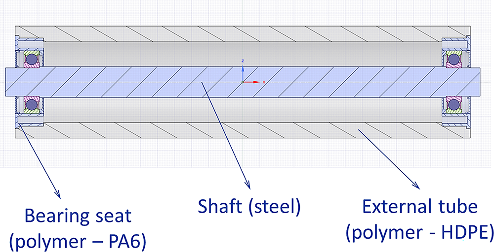
Figure 1: Longitudinal section of the polymeric roller with HDPE tube, PA6 bearing seats, and steel shaft
According to ABNT NBR 6678:2017 [5], rollers classified as “load rollers” must support specified loads and comply with limits on shaft deflection and bearing misalignment. The standard specifies a maximum allowable bearing misalignment angle β of 9′ (i.e., 0.15°). Fig. 2 illustrates the definition of the misalignment angle β.
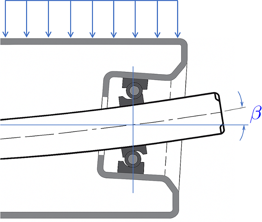
Figure 2: Bearing misalignment angle β as defined in [5]
A finite element model was built using Ansys Workbench version 19.2 to evaluate the structural response of the roller under the applied load, serving as the high-fidelity model in the surrogate-based optimization framework. By exploiting the roller’s geometric symmetry, only half of the structure was modeled, thereby reducing computational cost without compromising accuracy (see Fig. 3).
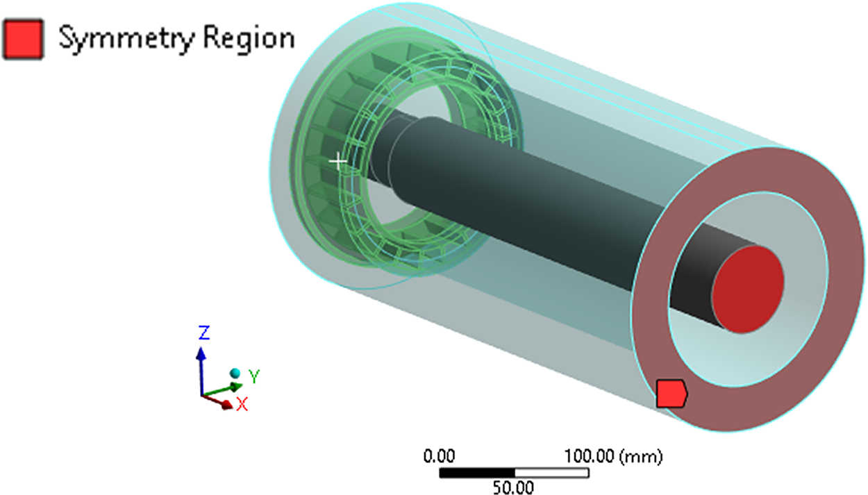
Figure 3: Half-symmetry geometrical model used to build the finite element model (bearing not shown)
According to [5], type 6310 bearings are recommended for rollers with diameters ranging from 178 mm to 203 mm and shafts of series 50. To represent these bearings in the finite element model, the SKF Bearing App extension available in ANSYS Workbench was used [23,24]. This extension incorporates the bearing stiffness into the finite element model without representing its full three-dimensional geometry, thus reducing the number of degrees of freedom and, consequently, the computational cost of the analysis. To create the bearings, the extension requires the specification of the roller’s external and internal surfaces in contact with the bearing, as well as a coordinate system defining the bearing’s location and orientation. In addition, the bearing code—6310 in this case—must be provided. Based on this input, the stiffness and parameters of the selected bearing are calculated and automatically incorporated into the model. Once the bearing stiffness was implemented, the next step was to define the loading and boundary.
The load was applied over a predefined contact width on the surface of the external tube. It was modeled as a uniformly distributed static load, based on Hertzian contact assumptions (see Johnston [25]), while neglecting the belt’s hyperelastic behavior for conservativeness. In addition, the roller self-weight was included in the model. Fig. 4 shows the applied loads and boundary conditions used in the model.
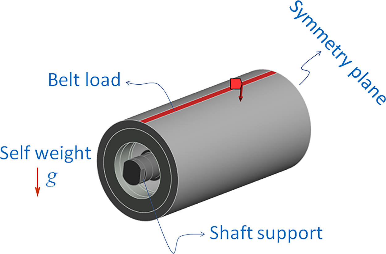
Figure 4: Loads and boundary conditions of the numerical model (bearing is modeled as spring elements and is not shown)
A mesh convergence study indicated that an average element size of 10 mm for tetrahedral solid elements was sufficient to ensure accurate results. Fig. 5 shows the mesh of the reference model. It is worth noting that, as the geometry (shaft and tube dimensions) changes during optimization, the finite element mesh is regenerated accordingly; however, the average element size of 10 mm is maintained throughout the process.
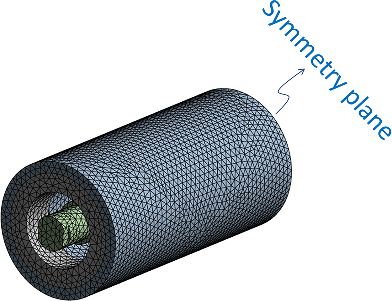
Figure 5: Finite element mesh of the roller (bearing is modeled as spring elements and is not shown)
As detailed in Section 2.3, the optimization process relied on the following simulation outputs:
• Maximum von Mises stress in the tube;
• Maximum vertical deflection at the shaft’s mid-span;
• Bearing misalignment angle β, calculated from the relative displacement between the upper and lower raceways.
2.3 Formulation of the Optimization Problem
The objective of the optimization was to minimize the mass of the roller while satisfying mechanical constraints related to structural performance. The design space was defined by two geometric variables, as illustrated in Fig. 6:
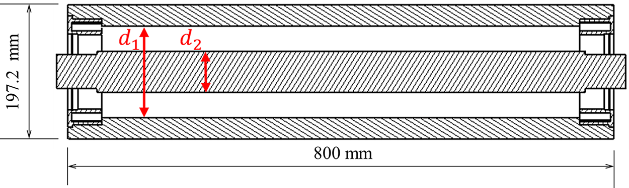
Figure 6: Design variables d1 and d2
• d1: Inner diameter of the external tube;
• d2: Diameter of the steel shaft.
The outer diameter of the tube was kept fixed, in order to comply with design specifications and ensure compatibility with the conveyor system.
The design variables d1 (inner tube diameter) and d2 (shaft diameter) were selected because they directly affect mass and the main structural constraints (stress, deflection, and misalignment). Also note that, with the external tube diameter fixed, d1 is directly related to the wall thickness. Other parameters, such as the bearing seat height, are indirectly linked to these two variables. The shaft support spacing was kept constant, as changing it would alter the roller’s baseline configuration and affect other conveyor system components. This simplification is acknowledged as a limitation of the present study.
The design constraints were initially defined to include:
• Maximum stress in the external tube;
• Maximum stress in the shaft;
• Maximum shaft misalignment angle β at the bearing locations;
• Maximum transverse (vertical) deflection of the shaft at mid-span.
However, preliminary finite element analyses indicated that the maximum stress in the steel shaft was well below the admissible limit in all configurations studied. Therefore, this constraint was deemed non-critical and was excluded from the optimization formulation.
The final optimization problem can thus be stated as:
where
Although viscoelastic polymers present a more complex behavior than metals, the von Mises criterion was adopted here as an effective engineering approximation, consistent with design practices for polymeric components [26,27]. More advanced failure criteria require extensive additional characterization and were considered beyond the scope of this work.
2.4 Surrogate Modeling and Optimization Strategy
To reduce computational effort during the optimization process, surrogate models (also known as metamodels) based on Radial Basis Functions (RBFs) were employed. These models approximate the mapping from design variables to the objective function and constraint functions, using responses obtained from finite element simulations at sample points generated via an optimized Latin Hypercube Sampling (LHS). A separate surrogate model was constructed for each criterion—namely, the objective function (mass) and the constraints (maximum stress, shaft deflection, and misalignment angle).
According to Keane et al. [17], an RBF metamodel is an interpolation scheme composed of several radially symmetric basis functions centered at the sample points in the design domain. The general form of the RBF interpolation function
where
Each sampling point consists of a pair of design variables (d1, d2) along with the corresponding values of: roller mass (objective function), maximum von Mises stress in the tube, vertical deflection in the mid span of the shaft and misalignment angle β.
The optimization procedure was conducted using the Globalized Bounded Nelder-Mead (GBNM) algorithm [21,22], which enhances the classical Nelder-Mead direct search method [28] by incorporating constraints and a probabilistic restart mechanism. This makes the algorithm suitable for constrained, non-convex problems without requiring gradient information.
The optimization was performed iteratively as follows:
1. RBF surrogates (one per criterion) were built using the current simulation dataset;
2. Using the surrogates, GBNM algorithm was applied to find the current minimum;
3. Two infill points were added: (i) the minimum found by the optimizer, and (ii) a randomly selected point within the design domain. These new points were evaluated via finite element simulations and their responses added to the dataset.
This loop was repeated until a predefined maximum number of simulations was reached. Fig. 7 presents a flowchart summarizing the surrogate-based optimization process.
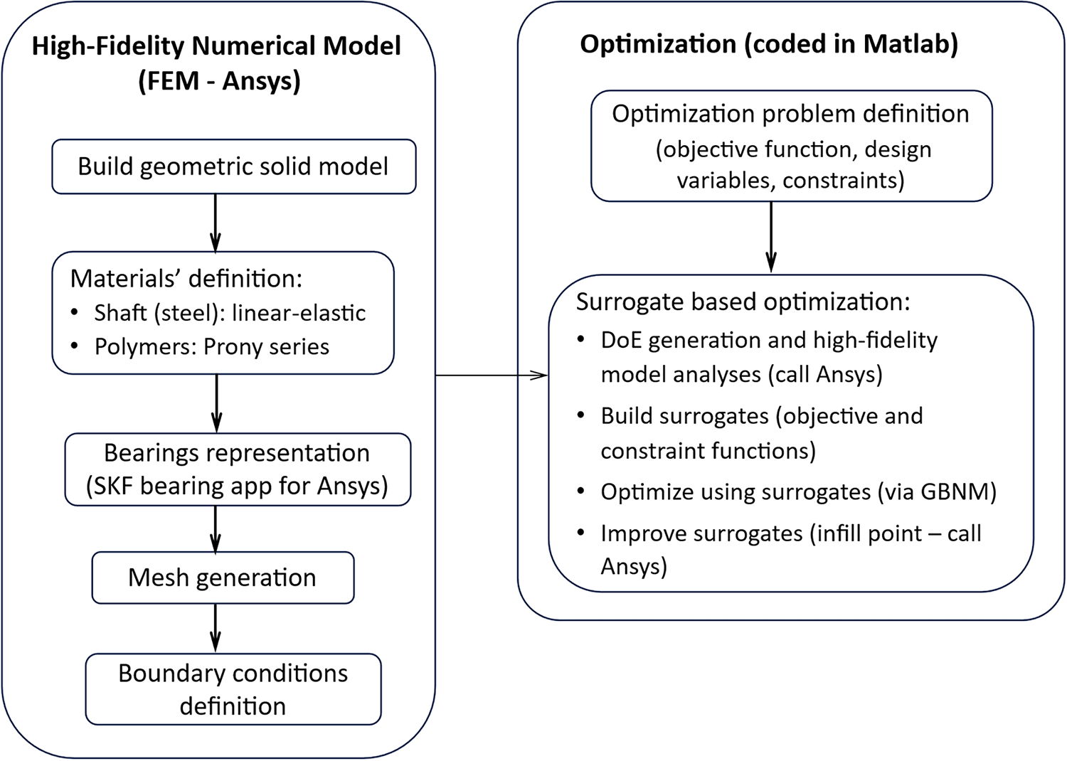
Figure 7: Surrogate-based optimization loop using RBF metamodels and the GBNM algorithm
Alternative approaches could also be applied to the present problem. For instance, genetic algorithms (GAs) could replace the GBNM optimizer, although they typically require a much larger number of evaluations to reach convergence. In addition, instead of a dimensional optimization, a topology optimization could be employed; however, it would require a fundamentally different formulation, which is currently under investigation by the authors. The surrogate-based GBNM approach was chosen in this work for its efficiency and robustness.
3 Experimental Characterization of Polymeric Materials (Relaxation Tests) and Prony’s Series Fitting
The finite element analysis carried out in this study incorporates the viscoelastic behavior of the polymeric materials used in the roller components. To this end, experimental characterization was performed to obtain the time-dependent mechanical properties of high-density polyethylene (HDPE) and polyamide 6 (PA6). These materials were selected due to their favorable mechanical performance and availability for industrial roller applications.
In the initial roller configuration, the external tube was manufactured from high-density polyethylene (HDPE), while the bearing seats were made of polyamide 6 (PA6). In the second optimization case, PA6 was selected for both components to increase structural stiffness. Both materials exhibit viscoelastic behavior, meaning that their mechanical response depends not only on the magnitude of the applied load (or stress) but also on the duration and rate of loading.
To characterize this behavior, stress relaxation tests were carried out. In these tests, a constant deformation was applied to a standard tensile specimen, and the resulting decay in force was recorded over time. Three specimens of each material were tested under controlled laboratory conditions at room temperature (approximately 23°C). All tests followed ASTM D2991-84 [29] and ASTM D638-22 [30], the latter used to define specimen geometry and dimensions.
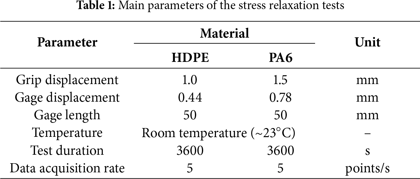
Fig. 8 presents the geometry and dimensions of the relaxation test specimen. Fig. 9 shows the actual specimens made of HDPE (a) and PA6 (b). Fig. 10 illustrates the experimental setup, showing (a) a general view of the universal testing machine (MTS 810) and (b) a close-up of a specimen instrumented with an MTS extensometer (model 632.25F-20). Table 1 summarizes the main parameters of the stress relaxation tests.
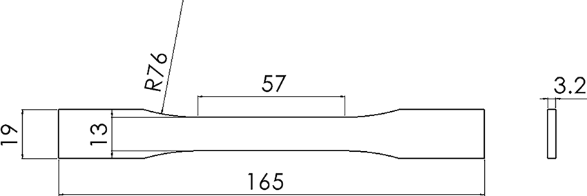
Figure 8: Relaxation test specimen geometry (dimensions in mm)
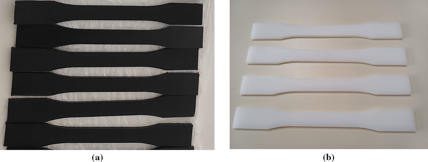
Figure 9: Actual relaxation specimens: (a) HDPE and (b) PA6
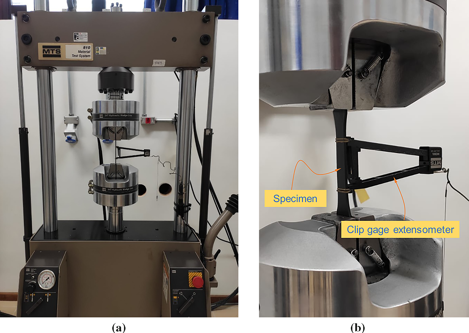
Figure 10: Stress relaxation test setup: (a) General view and (b) Detail of the specimen instrumented with an MTS extensometer
3.2 Relaxation Tests Results and Shear Modulus Evolution
During the stress relaxation tests, the applied force was recorded over time to capture the time-dependent reduction in stiffness. The resulting force-time curves were first converted into normal stress by dividing the measured force by the specimen’s cross-sectional area. Since the strain in the specimen remained constant throughout the test (imposed deformation), the Young’s modulus over time, E(t), was obtained by dividing the normal stress by this constant strain, calculated from the imposed displacement and the initial gauge length. Finally, the shear modulus, G(t), was then derived from E(t) using the isotropic elasticity relationship:
where v is the Poisson’s ratio, assumed to be time-independent for the tested materials.
Fig. 11 shows the evolution of G(t) for HDPE (a) and PA6 (b), representing the mean values among the tested specimens. The overall deviation among specimens of each material was below 7.5%. In both materials, a significant reduction in stiffness is observed during the first few minutes of testing, followed by a gradual stabilization toward an asymptotic value.
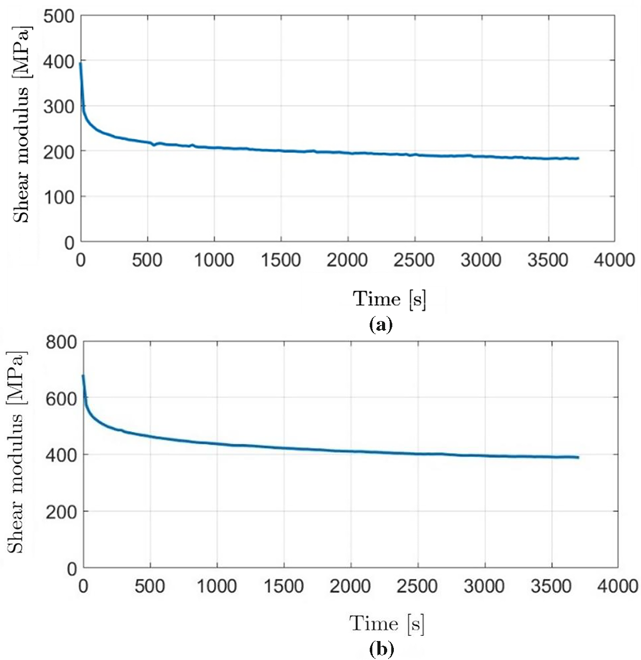
Figure 11: Time-dependent shear modulus (G (t)) of (a) HDPE and (b) PA6 obtained from stress relaxation tests
A linear isotropic viscoelastic model was adopted to represent the time-dependent behavior of the polymeric components. To incorporate the viscoelastic properties into the finite element simulations, the experimentally obtained shear modulus G(t) was approximated using a Prony series expansion [31,32], in which G(t) is expressed as a sum of exponential terms:
where
with:
the kernel functions can be equivalently expressed as:
here,
A nonlinear least-squares fitting procedure was used to determine the parameters
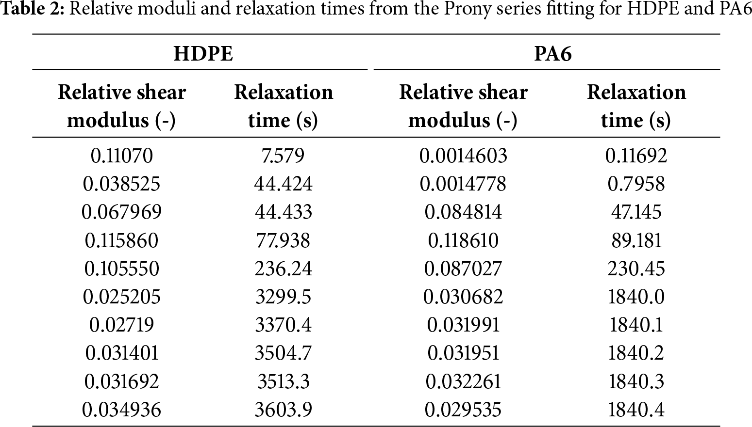
The fitted Prony series parameters were incorporated into the viscoelastic material definition in ANSYS Workbench, allowing the finite element simulations to account for the time-dependent mechanical response of the HDPE and PA6 components under load.
A comparative analysis between the two materials shows that PA6 exhibits a slower initial reduction in shear modulus compared to HDPE, suggesting improved short-term stiffness retention. This behavior is consistent with the higher modulus values typically reported for PA6 in the literature, and it may translate into better dimensional stability under service conditions. Conversely, HDPE experiences a steeper initial modulus drop, which should be considered in design applications requiring high stiffness during the first moments of loading.
It should be noted that the stress relaxation data used in this study represent the short-to medium-term response of the polymers. Long-term effects such as environmental degradation, creep over weeks or months, and temperature fluctuations were not included in the model due to time and scope constraints.
3.4 Structural Behavior of the Base Roller Design
Before carrying out the optimization, the structural behavior of the base roller design was evaluated through finite element simulations incorporating the viscoelastic properties of the polymeric components. This preliminary analysis was essential to verify that the numerical model accurately represents the mechanical response under the design loading conditions and complies with the specified constraints.
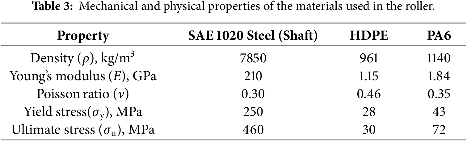
Table 3 summarizes the main physical and mechanical properties of the materials used in the roller components (apart from the viscoelastic properties addressed in the preceding subsections): SAE 1020 steel for the shaft, HDPE for the external tube in the initial configuration, and PA6 for the bearing seats, or for both components in the second optimization case.
In the simulation setup, the magnitude of the applied force followed the specifications of ABNT 6678:2017 [5] for the type of roller analyzed. This load was uniformly distributed over the tube’s contact region with the conveyor belt and was modeled in the finite element analysis considering symmetry, so that only half of the total prescribed force was applied. A constant load was applied for a period of 3000 s followed by unloading (Fig. 12). This simplified load history captures the viscoelastic response during service while keeping the simulation computationally feasible.
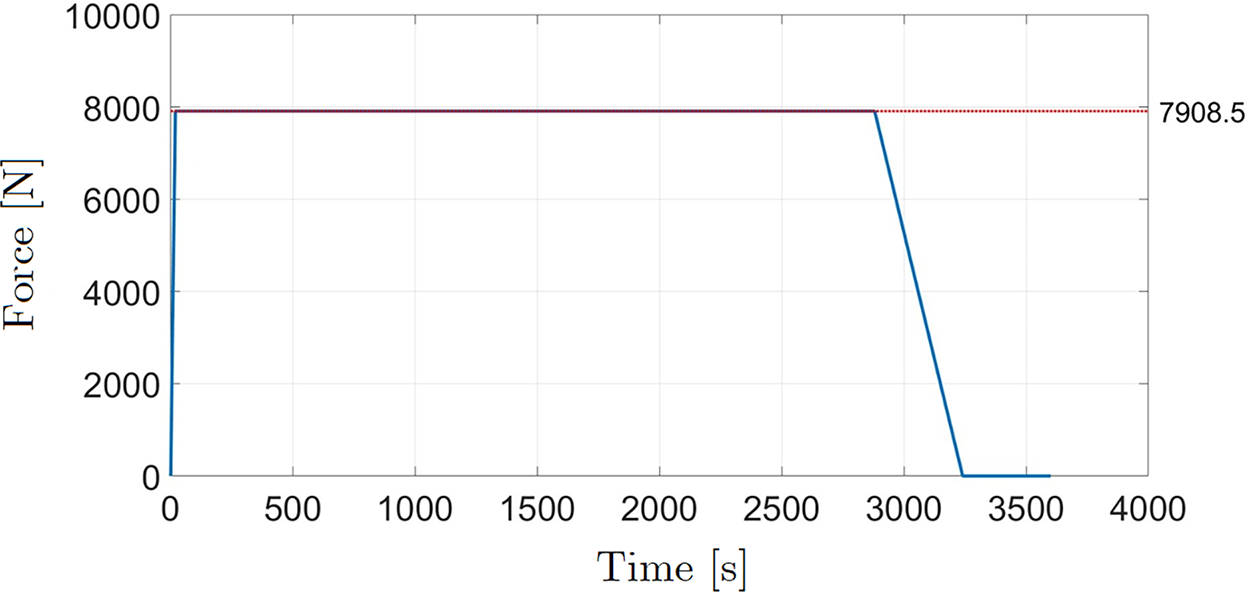
Figure 12: Applied force in the finite element model, corresponding to half of the total load defined in the standard for the analyzed roller type
Simulation results were evaluated over time to capture the viscoelastic response of the polymeric materials. Fig. 13a shows the evolution of the maximum tube deflection, Fig. 13b presents the shaft’s mid-span deflection, and Fig. 13c depicts the variation of the bearing misalignment angle β. The time-dependent behavior is evident, with displacements and misalignment increasing until reaching a peak value, then decreasing once the load is removed, and stabilizing at a residual value. The residual displacement is smaller in the shaft, since it is made of steel (with no viscoelastic effects), but it still exhibits some residual deformation due to the contribution of other components, such as the polymeric bearing seats. Fig. 14 shows the von Mises stress distribution at the critical instant (corresponding to the maximum stress during the simulation), highlighting the stress concentrations in the tube (HDPE), the bearing seat (PA6), and the shaft (steel).
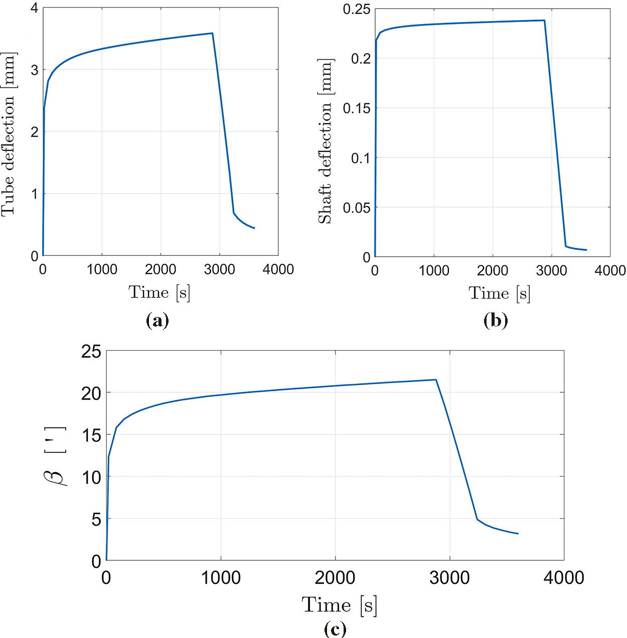
Figure 13: Time-dependent response for the base roller design: (a) maximum tube deflection; (b) mid-span shaft deflection; and (c) bearing misalignment angle β
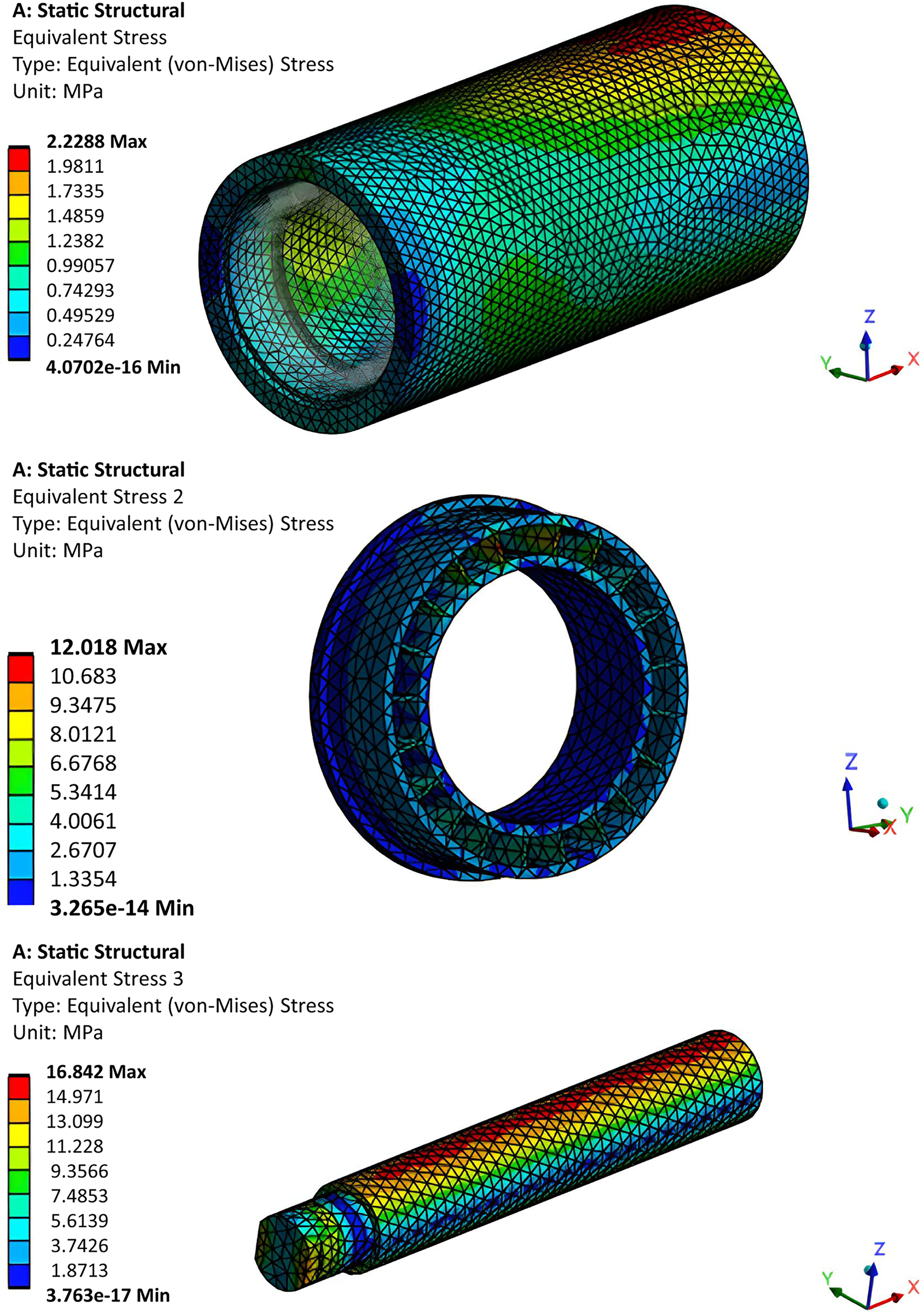
Figure 14: Von Mises stress distribution for the base roller design at the time of maximum stress. From top to bottom: tube, bearing seat and shaft
For comparison purposes, an additional analysis of the same model was performed without considering viscoelastic effects, i.e., assuming all materials to be purely linear elastic. It was observed that the analysis including viscoelastic effects produced a maximum tube deflection approximately 70% higher, a maximum shaft deflection about 15% higher, a bearing misalignment angle more than twice as large, and maximum stresses around 6% higher. These results highlight the importance of accounting for viscoelastic effects, particularly in this case for predicting translational and rotational deflections of the system.
4 Optimization Results and Discussion
This section presents the results of the dimensional optimization of the conveyor belt roller, considering two distinct material configurations:
• Case I: Roller with the external tube made of HDPE and bearing seats of PA6;
• Case II: Roller with both the external tube and bearing seats made of PA6.
The goal was to minimize the roller’s mass while satisfying structural constraints on the maximum von Mises stress in the tube, the shaft misalignment angle β, and the shaft’s transverse deflection. As described in Section 2, the optimization procedure employed Radial Basis Function (RBF) surrogate models combined with the Globalized Bounded Nelder-Mead (GBNM) algorithm. For each case, 20 design of experiments (DoE) points and 20 infill points were evaluated, resulting in a total of 40 high-fidelity finite element simulations. Each simulation required approximately 15 min to complete on a workstation equipped with an AMD Ryzen 5 2600X processor and 32 GB of RAM. Preliminary tests indicated that 40 simulations were sufficient to ensure stability of the optimization process, as no significant variation in the results was observed when additional simulations were considered. Thus, this value was adopted as a practical balance between accuracy and computational cost.
4.1 Results—Case I: HDPE Tube and PA6 Bearing Seats
In Case I, the material combination resulted in a compliant yet relatively flexible structure. While the HDPE tube provided a substantial mass reduction compared to a steel counterpart, its low stiffness adversely affected the shaft’s alignment. Table 4 summarizes a subset of design configurations evaluated in this case, including the initial design and four representative designs (A to D) obtained using the optimization procedure. Values highlighted in red indicate parameters that exceed the allowable limits.
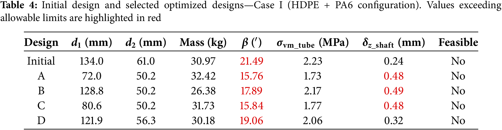
As shown in Table 4, although several configurations achieved mass reductions relative to the initial design, none met the constraint on the bearing misalignment angle β, which remained well above the allowable limit of 9′ for all designs. The misalignment angle ranged from 15.76′ to over 21′ across all designs. In addition, some configurations also failed to meet the shaft deflection limit (
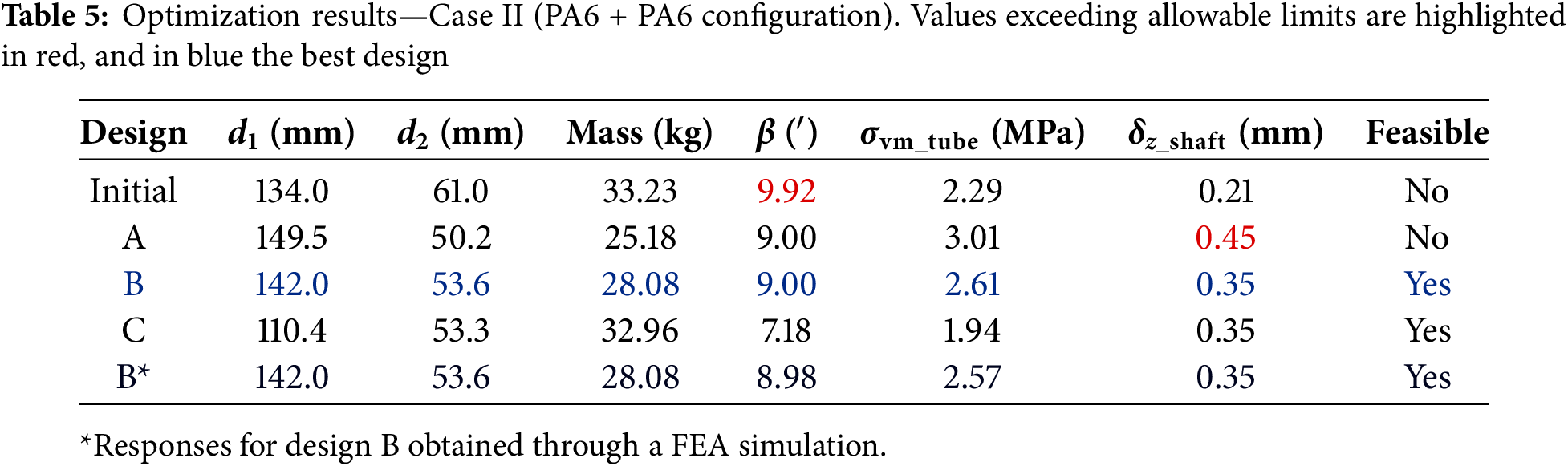
4.2 Results—Case II: PA6 Tube and PA6 Bearing Seats
Table 5 summarizes the results for the initial configuration and three representative optimized designs (A, B, and C) obtained in Case II, where both the external tube and the bearing seats were made of PA6. The responses shown in Table 5 for designs A, B, and C correspond to predictions from the surrogate model constructed during the optimization procedure. The initial design and design A are unfeasible, with the former violating the allowable limit for β and the latter violating the shaft deflection constraint. The best feasible configuration identified was design B (highlighted in light blue in the table). To verify the accuracy of the surrogate model and obtain a more reliable final evaluation, the best configuration (design B) was also simulated using the high-fidelity FEA model. The corresponding responses are presented in the table as design B* (highlighted in dark blue in the table).
For a clearer comparison between the initial and optimized configurations, Fig. 15 illustrates the main response parameters for Case II (initial vs. design B*), with the bar heights normalized relative to the initial configuration (100%). The absolute values of each parameter are indicated inside the bars.
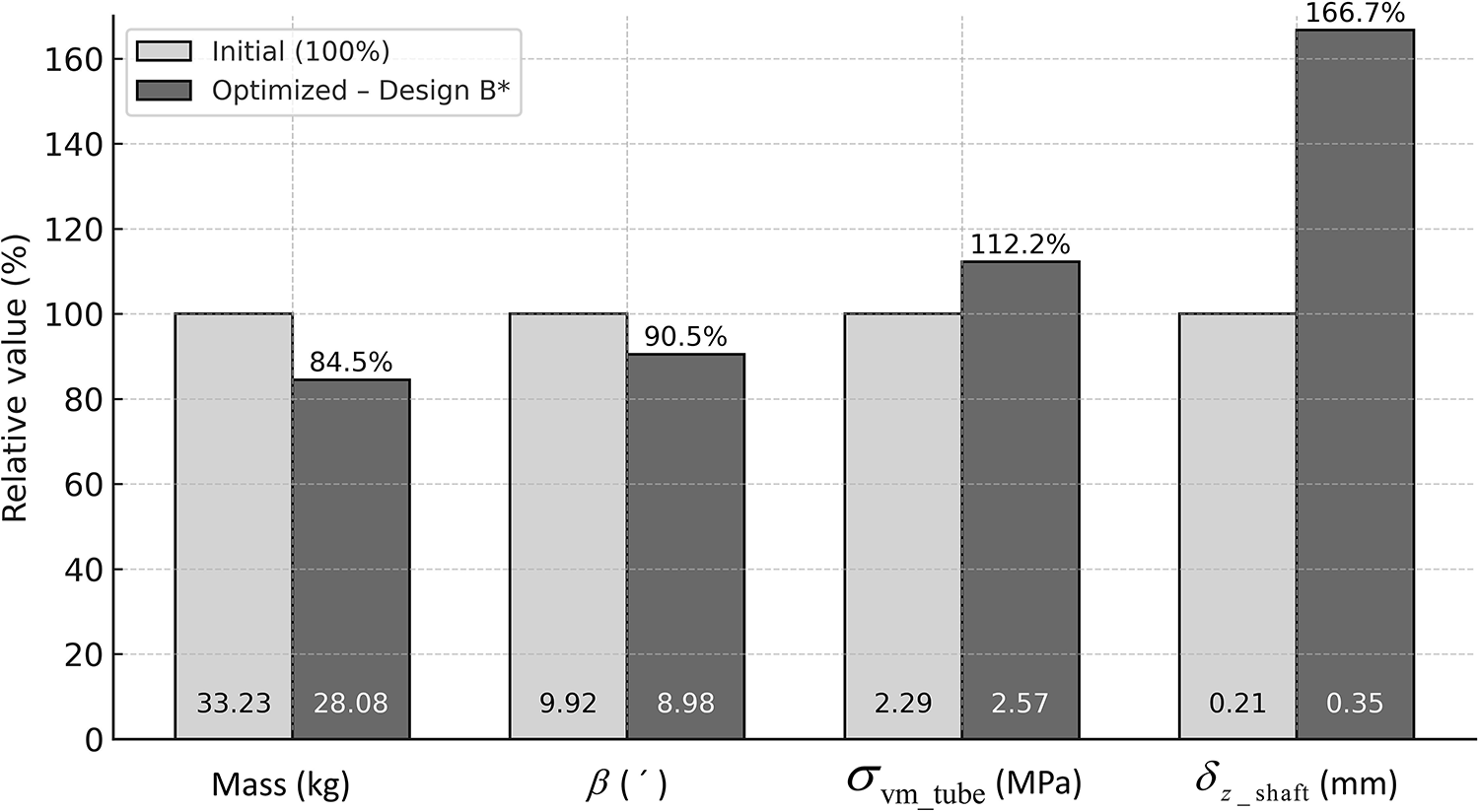
Figure 15: Relative comparison between the initial and the best optimized configuration (design B*) for Case II (PA6 + PA6)
The optimized configuration (design B) achieved a mass reduction of 5.15 kg, corresponding to approximately 15.5% compared to the initial design. Importantly, all imposed constraints were satisfied:
• Bearing misalignment angle (β): reduced by approximately 10% compared to the initial design.
• Shaft deflection (
• Von Mises stress in the tube (
The optimization revealed a beneficial trade-off between tube and shaft dimensions: increasing the tube diameter improved its stiffness, which allowed a reduction in shaft diameter without violating deflection or misalignment limits. This balance contributed to the mass reduction while maintaining structural integrity. Furthermore, comparison between the surrogate model predictions and the high-fidelity FEA results (design B vs. B*) showed excellent agreement, with discrepancies below 1.6% across all design criteria.
4.3 Discussion and Interpretation
The optimization process showed that:
• Material stiffness is essential to achieve feasible designs: replacing HDPE with PA6 in the tube improved both mechanical performance and feasibility.
• Tube stiffness has a greater influence on shaft alignment than shaft stiffness, as observed in both cases.
• Surrogate-based optimization with RBF models efficiently guided the search, significantly reducing the number of required simulations.
The methodology successfully integrated experimental viscoelastic characterization, numerical modeling, and computational optimization, resulting in designs that meet real-world engineering constraints while providing significant mass reduction and ensuring operational safety. Although a direct comparison with previous studies is limited due to differences in materials, geometries and modeling assumptions, the obtained 15.5% mass reduction in Case II and full compliance with all constraints are consistent with the range of improvements reported in similar optimization-based lightweight component studies. Reported reductions typically vary between 10% and 20% (for instance, Ceniz et al. [10] achieved approximately 19% for a polymeric conveyor roller) reinforcing the validity and effectiveness of the proposed surrogate-based approach.
The main objective of this work was to develop and apply a structural optimization methodology to minimize the mass of a polymeric roller used in ore conveyor belt systems, while ensuring compliance with design constraints defined by the Brazilian standard ABNT NBR 6678:2017.
To reduce the computational cost associated with repeated finite element simulations (the so-called direct optimization), a surrogate-based optimization strategy was adopted. Radial Basis Function (RBF) metamodels were used to approximate both the objective function (roller mass) and the constraint functions (von Mises stress, shaft deflection, and misalignment angle). The optimization algorithm employed was the Globalized Bounded Nelder-Mead (GBNM) method, which combines local search with global exploration and does not require gradient information.
Two different material configurations were investigated:
• Case I: Roller with external tube made of HDPE and bearing seats made of PA6;
• Case II: Roller with both tube and bearing seats made of PA6.
In Case I, although several configurations achieved mass reductions, none satisfied the constraint on the maximum shaft misalignment angle. This confirmed that the use of HDPE in the external tube, despite its low density, compromises the structural stiffness required for shaft alignment.
In Case II, the increased stiffness provided by PA6 enabled the identification of a feasible design configuration that met all design criteria. A mass reduction of 15.5% (5.15 kg) was achieved relative to the initial design.
The viscoelastic behavior of the polymeric materials was incorporated into the finite element model using Prony series parameters obtained from experimental stress relaxation tests. This approach improved simulation accuracy compared to purely linear-elastic assumptions, particularly for long-duration loading. Nonetheless, effects such as rotational dynamics, environmental aging, and vibrations were not considered, which could influence long-term performance. The methodology remains consistent with approaches reported in the literature and complies with the recommendations of ABNT NBR 6678:2017.
It should be emphasized that the present study is limited to numerical analyses, as no physical prototype of the optimized roller was fabricated or experimentally validated. Future experimental testing under operational conditions is therefore recommended to confirm the numerical predictions and to assess the long-term performance and durability of the polymeric components.
The methodology proposed in this work demonstrates that the integration of experimental material characterization, viscoelastic modeling, and surrogate-based optimization is a viable and effective approach to designing lightweight, compliant, and structurally efficient polymeric rollers for ore transport applications. The novelty of this work lies in combining experimental viscoelastic characterization with surrogate-based optimization, a contribution not previously reported in the design of conveyor belt rollers.
Finally, the long-term durability of polymers under mining conditions remains a concern, as hygrothermal aging and creep may lead to misalignment over extended service. Future studies should address these issues by exploring additives to improve resistance to humidity and temperature effects.
Acknowledgement: The authors would like to thank Vale S.A. company and the Institute of Technology Vale (ITV) for financing this research. The Brazilian funding agencies CNPq and CAPES are also acknowledged.
Funding Statement: This research was partially funded by Vale S.A. company (www.vale.com) and the Institute of Technology Vale (ITV—www.itv.org), grant number SAP 4600048682.
Author Contributions: The authors confirm contribution to the paper as follows: Conceptualization: Marco Antonio Luersen and Rafiq Said Dias Jabour; Methodology: Rafiq Said Dias Jabour, Marco Antonio Luersen and Euclides Alexandre Bernardelli; Numerical analyses: Rafiq Said Dias Jabour; Experimental tests (execution): Rafiq Said Dias Jabour and Euclides Alexandre Bernardelli; Experimental tests (supervision): Euclides Alexandre Bernardelli; Validation: Rafiq Said Dias Jabour; Data curation: Rafiq Said Dias Jabour; Writing—original draft preparation: Marco Antonio Luersen; Writing—review and editing: Rafiq Said Dias Jabour, Marco Antonio Luersen and Euclides Alexandre Bernardelli; Supervision: Marco Antonio Luersen. All authors reviewed the results and approved the final version of the manuscript.
Availability of Data and Materials: The data that support the findings of this study are available from the corresponding author, [Marco Antonio Luersen], upon reasonable request.
Ethics Approval: Not applicable.
Conflicts of Interest: The authors declare no conflicts of interest to report regarding the present study.
References
1. Zimroz R, Hardygóra M, Blazej R. Maintenance of belt conveyor systems in Poland—an overview. In: Proceedings of the 12th International Symposium Continuous Surface Mining—Aachen 2014. Cham, Switzerland: Springer International Publishing; 2015. p. 21–30. doi:10.1007/978-3-319-12301-1_3. [Google Scholar] [CrossRef]
2. Dąbek P, Krot P, Wodecki J, Zimroz P, Szrek J, Zimroz R. Measurement of idlers rotation speed in belt conveyors based on image data analysis for diagnostic purposes. Measurement. 2022;202(2):111869. doi:10.1016/j.measurement.2022.111869. [Google Scholar] [CrossRef]
3. Opasiak T, Margielewicz J, Gąska D, Haniszewski T. Rollers for belt conveyors in terms of rotation resistance and energy efficiency. Transp Probl. 2022;17(2):57–68. doi:10.20858/tp.2022.17.2.05. [Google Scholar] [CrossRef]
4. Konieczna-Fuławka M. Energy-saving solutions applied in belt conveyors: a literature review. Energies. 2025;18(12):3019. doi:10.3390/en18123019. [Google Scholar] [CrossRef]
5. NBR 6678:2017. Continuous conveyors—belt conveyors—rollers—design, selection and standardization—machines and mechanical equipment. Rio de Janeiro, Brazil: Brazilian Association of Technical Standards (ABNT); 2017. [Google Scholar]
6. Berto F, Campagnolo A, Chebat F, Cincera M, Santini M. Fatigue strength of steel rollers with failure occurring at the weld root based on the local strain energy values: modelling and fatigue assessment. Int J Fatigue. 2016;82:643–57. doi:10.1016/j.ijfatigue.2015.09.023. [Google Scholar] [CrossRef]
7. Knauss WG, Emri I, Lu H. Mechanics of polymers: viscoelasticity. In: Springer handbook of experimental solid mechanics. Boston, MA, USA: Springer; 2008. p. 49–96. doi:10.1007/978-0-387-30877-7_3. [Google Scholar] [CrossRef]
8. Youssef G. Applied mechanics of polymers: properties, processing, and behavior. Amsterdam, The Netherlands: Elsevier; 2021. [Google Scholar]
9. Kouketsu F, Pacholok D, Cousseau T, da Silva CH. Abrasive wear resistance of idler roll polymeric materials. Surf Topogr: Metrol Prop. 2022;10(3):034002. doi:10.1088/2051-672x/ac89a2. [Google Scholar] [CrossRef]
10. Ceniz JP, de Martins RS, Luersen MA, Cousseau T. Structural optimization of metal and polymer ore conveyor belt rollers. Comput Model Eng Sci. 2022;133(3):601–18. doi:10.32604/cmes.2022.021011. [Google Scholar] [CrossRef]
11. Christensen PW, Klarbring A. An introduction to structural optimization. Berlin, Germany: Springer Science & Business Media; 2008. [Google Scholar]
12. Jiang P, Zhou Q, Shao X. Surrogate model-based engineering design and optimization. Berlin/Heidelberg, Germany: Springer; 2020. doi:10.1007/978-981-15-0731-1. [Google Scholar] [CrossRef]
13. Pholdee N, Sujin B, Nuantong W. Kriging surrogate-based genetic algorithm optimization for blade design of a horizontal AxisWind turbine. Comput Model Eng Sci. 2021;126(1):261–73. doi:10.32604/cmes.2021.012349. [Google Scholar] [CrossRef]
14. Samadian D, Muhit IB, Dawood N. Application of data-driven surrogate models in structural engineering: a literature review. Arch Comput Meth Eng. 2025;32(2):735–84. doi:10.1007/s11831-024-10152-0. [Google Scholar] [CrossRef]
15. Liang J, Lou Y, Yu M, Bi Y, Yu K. A survey of surrogate-assisted evolutionary algorithms for expensive optimization. J Membr Comput. 2025;7(2):108–27. doi:10.1007/s41965-024-00165-w. [Google Scholar] [CrossRef]
16. Sadiq MA, Kovács G. Optimization of composite sandwich structures: a review. Machines. 2025;13(7):536. doi:10.3390/machines13070536. [Google Scholar] [CrossRef]
17. Keane A, Forrester A, Sobester A. Engineering design via surrogate modelling: a practical guide. Chichester, UK: John Wiley & Sons; 2008. doi:10.2514/4.479557. [Google Scholar] [CrossRef]
18. Hussain MF, Barton RR, Joshi SB. Metamodeling: radial basis functions, versus polynomials. Eur J Oper Res. 2002;138(1):142–54. doi:10.1016/S0377-2217(01)00076-5. [Google Scholar] [CrossRef]
19. Rodrigues MT, Luersen MA. Crashworthiness optimization of honeycomb structures under out-of-plane impact using radial basis functions. Mater Und Werkstofftech. 2020;51(5):654–64. doi:10.1002/mawe.201900233. [Google Scholar] [CrossRef]
20. Kalita K, Chakraborty S, Madhu S, Ramachandran M, Gao XZ. Performance analysis of radial basis function metamodels for predictive modelling of laminated composites. Materials. 2021;14(12):3306. doi:10.3390/ma14123306. [Google Scholar] [PubMed] [CrossRef]
21. Luersen MA, Riche RL. Globalized Nelder-Mead method for engineering optimization. Comput Struct. 2004;82(23–26):2251–60. doi:10.1016/j.compstruc.2004.03.072. [Google Scholar] [CrossRef]
22. Luersen MA, Riche RL, Guyon F. A constrained, globalized, and bounded Nelder-Mead method for engineering optimization. Struct Multidiscip Optim. 2004;27(1):43–54. doi:10.1007/s00158-003-0320-9. [Google Scholar] [CrossRef]
23. Ansys. SKF Bearing [Internet]. [cited 2025 Aug 15]. Available from: https://developer.ansys.com/app/skf/skf-bearing/1-6. [Google Scholar]
24. SKF. SKF Bearing App in ANSYS Mechanical [Internet]. [cited 2025 Aug 15]. Available from: https://productselect.skf.com/ansys/index.html. [Google Scholar]
25. Johnson KL. Contact mechanics. Cambridge, UK: Cambridge University Press; 1985. [Google Scholar]
26. Shahin A, Barsoum I, Korkees F. Analysis of a HDPE flanged connection with a time and temperature dependent constitutive behavior. Int J Press Vessel Pip. 2021;191(3):104375. doi:10.1016/j.ijpvp.2021.104375. [Google Scholar] [CrossRef]
27. Amirapu SL, Nelapati GS, Yalamanchili H, Badgayan ND, Sahu SK. HDPE based polymeric nanodiamond nanocomposite for total knee arthoplasty: a finite element based approach. Mater Today Proc. 2022;56(10):1622–8. doi:10.1016/j.matpr.2022.03.290. [Google Scholar] [CrossRef]
28. Nelder JA, Mead R. A simplex method for function minimization. Comput J. 1965;7(4):308–13. doi:10.1093/comjnl/7.4.308. [Google Scholar] [CrossRef]
29. ASTM D2991. Standard practice for testing stress-relaxation of plastics. West Conshohocken, PA, USA: ASTM—American Society for Testing and Materials; 1984. [Google Scholar]
30. ASTM D638. Standard test method for tensile properties of plastics. West Conshohocken, PA, USA: ASTM—American Society for Testing and Materials; 2022. [Google Scholar]
31. Soussou JE, Moavenzadeh F, Gradowczyk MH. Application of prony series to linear viscoelasticity. Trans Soc Rheol. 1970;14(4):573–84. doi:10.1122/1.549179. [Google Scholar] [CrossRef]
32. Chen T. Determining a prony series for a viscoelastic material from varying time strain data [Internet]. 2000 [cited 2025 May 1]. Hampton, VA, USA: NASA Langley Research Center. Available from: https://dl.acm.org/doi/pdf/10.5555/886732. [Google Scholar]
Cite This Article
 Copyright © 2026 The Author(s). Published by Tech Science Press.
This work is licensed under a Creative Commons Attribution 4.0 International License , which permits unrestricted use, distribution, and reproduction in any medium, provided the original work is properly cited.
 Downloads
 Citation Tools