
 Submit a Paper
 Propose a Special lssue
 Open Access
ARTICLE
Numerical Investigation of Porosity and Aggregate Volume Ratio Effects on the Mechanical Behavior of Lightweight Aggregate Concrete
1 Key Laboratory of Urban Security and Disaster Engineering, Ministry of Education, Beijing University of Technology, Beijing, 100124, China
2 Department of Allied Engineering Sciences, Faculty of Engineering, The Hashemite University, P.O. Box 330127, Zarqa, 13133, Jordan
3 Department of Computer Science and Engineering, College of Applied Studies and Community Service, King Saud University, Riyadh, 11495, Saudi Arabia
* Corresponding Author: Yijiang Peng. Email:
(This article belongs to the Special Issue: Computational Modeling of Mechanical Behavior of Advanced Materials)
Computers, Materials & Continua 2026, 86(3), 20 https://doi.org/10.32604/cmc.2025.074068
Received 30 September 2025; Accepted 14 November 2025; Issue published 12 January 2026
 View Full Text
 Download PDF
Abstract
In modern construction, Lightweight Aggregate Concrete (LWAC) has been recognized as a vital material of concern because of its unique properties, such as reduced density and improved thermal insulation. Despite the extensive knowledge regarding its macroscopic properties, there is a wide knowledge gap in understanding the influence of microscale parameters like aggregate porosity and volume ratio on the mechanical response of LWAC. This study aims to bridge this knowledge gap, spurred by the need to enhance the predictability and applicability of LWAC in various construction environments. With the help of advanced numerical methods, including the finite element method and a random circular aggregate model, this study critically evaluates the role played by these microscale factors. We found that an increase in the aggregate porosity from 23.5% to 48.5% leads to a drastic change of weakness from the bonding interface to the aggregate, reducing compressive strength by up to 24.2% and tensile strength by 27.8%. Similarly, the increase in the volume ratio of lightweight aggregate from 25% to 40% leads to a reduction in compressive strength by 13.0% and tensile strength by 9.23%. These results highlight the imperative role of microscale properties on the mechanical properties of LWAC. By supplying precise quantitative details on the effect of porosity and aggregate volume ratio, this research makes significant contributions to construction materials science by providing useful recommendations for the creation and optimization of LWAC with improved performance and sustainability in construction.Keywords
Lightweight aggregate concrete (LWAC) has gained considerable attention in recent decades as a sustainable alternative to conventional normal-weight concrete. The increasing demand for energy-efficient and environmentally friendly construction materials has driven interest in LWAC due to its distinctive ability to reduce structural self-weight while maintaining acceptable strength and durability. The reduction in density achieved by incorporating lightweight aggregates (LWA) not only decreases the dead load of structures but also enables the design of more slender elements, reduces foundation loads, and lowers transportation costs. Furthermore, LWAC exhibits improved thermal insulation, enhanced fire resistance, and better energy absorption capacity, all of which make it particularly suitable for modern construction practices emphasizing sustainability and resilience [1].
The key distinguishing factor between LWAC and conventional concrete lies in the replacement of natural coarse aggregates with lightweight aggregates such as expanded clay, shale, perlite, pumice, or recycled materials. These aggregates possess lower density and higher porosity, which confer the desirable reduction in self-weight but also introduce challenges related to strength and durability. Previous research has demonstrated that the mechanical properties of LWAC are strongly influenced by aggregate type, density, porosity, and replacement ratio [2]. Empirical and analytical models have been proposed to predict LWAC compressive strength, with some achieving predictive accuracies exceeding 90% [2]. Beyond strength, LWAC has also shown superior performance under high-temperature conditions, where thermal strain compatibility between the mortar matrix and lightweight aggregates results in better residual strength compared to normal-weight concrete [3,4].
One of the critical microstructural factors that determines LWAC performance is the interfacial transition zone (ITZ). This region, which forms around the aggregates, is widely recognized as the weakest link in cementitious composites. Cracking and failure in concrete often initiate and propagate through the ITZ, making its characteristics essential in governing macroscopic mechanical performance. The quality of the ITZ in LWAC is strongly affected by the porosity and absorption capacity of the lightweight aggregates, which influence local water-to-binder ratios and hydration processes. Studies have confirmed that ITZ properties vary with aggregate type, water–cement ratio, and supplementary cementitious materials [5–7]. Numerical and experimental investigations suggest that while elastic modulus is relatively insensitive to ITZ properties, compressive strength, fracture toughness, and crack propagation behavior are significantly affected [6,8,9].
With the advancement of computational techniques, mesoscale numerical modeling has become an indispensable tool for exploring the micromechanical behavior of LWAC [10,11]. Various methods, including the Base Force Element Method (BFEM), discrete element approaches, lattice models, and phase-field formulations, have been successfully applied to simulate complex processes such as crack initiation, fracture propagation, tensile failure, and compressive response in cement-based composites [12–15]. These approaches allow researchers to virtually dissect the influence of aggregate distribution, morphology, and porosity on overall material performance. However, despite notable progress, current models still face limitations in accurately capturing the interplay between lightweight aggregate porosity, aggregate volume ratio, and ITZ behavior. Most existing studies have either focused on generic meso-mechanical characteristics or relied on simplified assumptions that overlook the porosity-dependent micromechanics of lightweight aggregates. As a result, the predictive capability of such models remains constrained when applied to real-world LWAC applications.
The present study aims to address this critical gap by systematically investigating the effect of lightweight aggregate porosity and volume ratio on the mechanical performance of LWAC through advanced mesoscale modeling. Building upon established random circular aggregate models [16], this research introduces refinements that explicitly incorporate microscale variables such as aggregate density, particle size distribution, Poisson’s ratio, water–cement ratio, and interfacial transition zone properties. Particular emphasis is placed on quantifying how aggregate porosity governs crack initiation, damage evolution, and failure patterns under uniaxial compression and tension. By bridging microscale aggregate features with macroscale mechanical response, this study offers new insights into the damage mechanisms of LWAC.
Ultimately, the findings of this research are expected to provide practical guidelines for optimizing LWAC mix design, balancing the trade-offs between reduced density and mechanical reliability. The outcomes contribute not only to advancing fundamental understanding of LWAC micromechanics but also to enhancing structural efficiency, fire safety, and sustainability in lightweight concrete construction.
2 Materials and Numerical Calibration
This study employs a numerical approach to investigate the mechanical behavior of lightweight aggregate concrete (LWAC) at the mesoscale. No new physical experiments were conducted; instead, all material parameters were derived from previously published experimental studies to ensure realistic and reliable numerical simulations. The primary sources of material data are references [16–18], which provide detailed measurements of the elastic modulus, Poisson’s ratio, tensile strength, compressive strength, and porosity of lightweight aggregate particles and LWAC specimens.
The numerical specimens were constructed using a random aggregate mesoscopic model, representing LWAC as a three-phase material composed of lightweight aggregates, cement mortar, and the interface transition zones. Porosity and volume ratios of aggregates were incorporated as key variables, and their values were taken from experimental studies to reflect realistic ranges: porosity values of 23.5%, 28.5%, 33.5%, 38.5%, 43.5%, and 48.5% and aggregate volume ratios of 25%, 30%, 35%, and 40%.
To ensure the simulations accurately replicate real material behavior, the numerical models were calibrated using experimental trends reported in the literature. Specifically, peak stresses, peak strains, and stress-strain relationships under uniaxial compression and tension were cross-validated against published experimental data. Damage and failure modes of the numerical specimens were also compared with observed experimental patterns to verify the model’s predictive capability.
By explicitly referencing experimental data and using them to parameterize the simulations, this study provides numerically generated results that are firmly grounded in empirical evidence, ensuring that conclusions drawn from the simulations are physically meaningful and applicable to practical LWAC design.
Ordinary Portland cement (42.5R grade) was used as the binder. Natural river sand with a fineness modulus of 2.6 served as the fine aggregate. Expanded shale lightweight aggregate with a bulk density of 950 kg/m3 was employed as the coarse aggregate. A polycarboxylate-based superplasticizer was added to improve workability. Tap water was used for mixing and curing.
The mixture proportions of the lightweight aggregate concrete (LWAC) are summarized in Table 1.
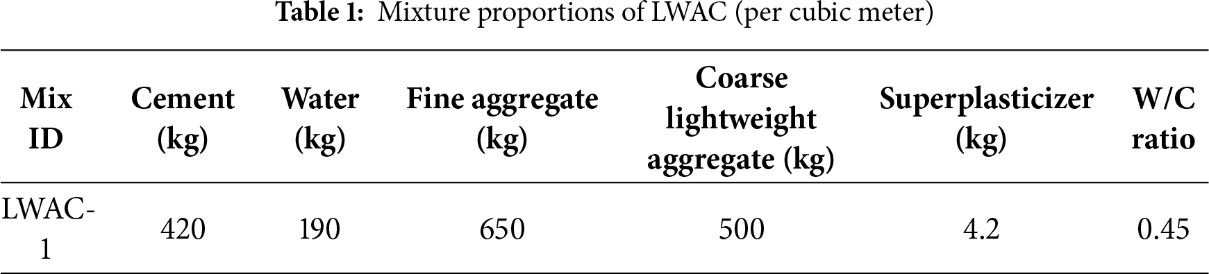
Concrete was mixed in a pan mixer and cast into 100 mm × 100 mm × 100 mm cubes and 100 mm × 200 mm cylinders. After 24 h, the specimens were demolded and cured in water at 20 ± 2°C until testing at 28 days.
(1) Compressive strength was tested on cubic specimens according to ASTM C39.
(2) Splitting tensile strength was measured on cylindrical specimens following ASTM C496.
(3) Density and workability were evaluated in accordance with ASTM C138 and ASTM C143, respectively.
To ensure reliability of the literature data, the above experimental results were compared with reference values reported in previous studies on LWAC. The compressive strength of LWAC-1 was measured at 32.4 MPa, which falls within the reported range of 30–35 MPa for similar mix designs. The splitting tensile strength was 2.6 MPa, closely matching the literature-reported ratio of 7%–10% of compressive strength. The measured density was 1860 kg/m3, which also aligns with published LWAC values (1800–1900 kg/m3).
These initial experiments confirm that the mechanical performance and density of the prepared LWAC are consistent with literature data, thereby validating the reliability of the reported ranges used in this study.
The mechanical behavior of lightweight aggregate concrete (LWAC) was simulated using a two-dimensional mesoscopic finite element approach based on the Base Force Element Method (BFEM). The LWAC specimens were modeled as a three-phase material comprising lightweight aggregates (LWA), cement mortar, and the interfacial transition zones (ITZs). The random circular aggregate model [16] was extended to explicitly incorporate microscale variables, including aggregate density, particle size, Poisson’s ratio, water–cement ratio, and ITZ mechanical properties.
The random circular aggregate model was generated using a random sequential addition (RSA) algorithm in MATLAB R2023a. Aggregate diameters followed Fuller’s particle size distribution curve, ensuring realistic gradation within a 2D projection of the experimental particle range (5–20 mm). The probability density function
where
Fig. 1 illustrates the overall process, including input parameter definition, random placement, overlap checking, ITZ generation, and meshing.
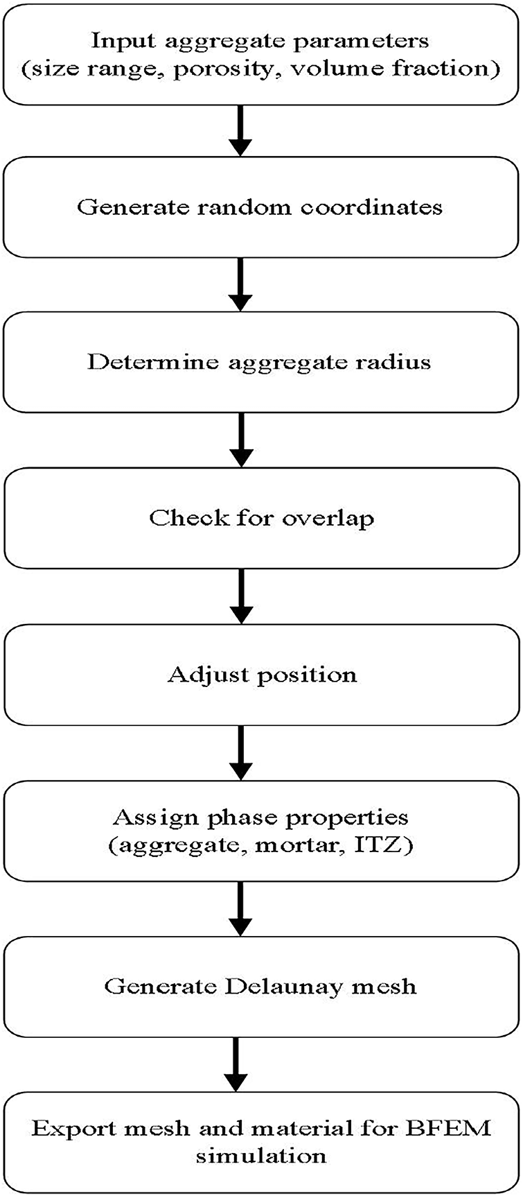
Figure 1: Flowchart of the random aggregate generation and meshing process
The specimens were discretized using a Delaunay triangulation mesh, providing high-quality triangular elements for accurate stress distribution and crack propagation analysis. The mesh size was chosen to ensure at least 8–10 elements along the diameter of each aggregate particle. A mesh sensitivity study was conducted to ensure that the predicted mechanical properties converged; no significant changes were observed when the mesh was further refined.
(1) Compression Simulations: The bottom boundary of each specimen was fully constrained in both horizontal and vertical directions. A uniform vertical displacement was applied to the top boundary to simulate uniaxial compression. Lateral boundaries were free to move.
(2) Tension Simulations: The bottom boundary was fixed vertically, while a vertical displacement was applied at the top boundary. Lateral boundaries remained free.
(3) These conditions ensured realistic stress states and prevented artificial constraints on specimen deformation.
3.8 Constitutive Models and Material Properties
Each phase in the LWAC was assigned isotropic elastic–plastic damage properties:
(1) Cement Mortar: Elastic modulus, Poisson’s ratio, and tensile/compressive strengths were taken from experimental data [8].
(2) Lightweight Aggregates: Porosity-dependent elastic modulus and strengths were calculated using Eqs. (3)–(10) (Section 4).
(3) Interfacial Transition Zone (ITZ): Modeled as a thin (0.15 mm) porous layer surrounding each aggregate. The ITZ mechanical properties were defined as follows:
1) Elastic modulus
2) Tensile strength
3) Compressive strength
These ratios were selected according to [8] and confirmed through parameter sensitivity analysis in Section 3.11.
3.9 Convergence and Solution Procedure
The BFEM simulations employed an incremental displacement control approach. Nonlinear equilibrium iterations were solved using a Newton–Raphson scheme. Convergence was achieved when the norm of residual forces fell below 1 × 10⁻⁶ of the total applied load. Adaptive time stepping was used near peak stress and post-peak softening regions to ensure stable convergence and accurate capture of crack initiation and propagation.
The numerical model was validated against experimental data from [8], including uniaxial compression and tension tests for specimens with varying aggregate porosities (23.5%–48.5%) and volume fractions (25%–40%). The predicted stress–strain curves, peak strengths, and failure modes showed excellent agreement with experimental observations, confirming the reliability of the simulation methodology.
3.11 Parameter Sensitivity Analysis
To evaluate the robustness and reliability of the proposed mesoscopic model, a parameter sensitivity analysis was conducted to quantify the influence of key modeling parameters on the predicted mechanical properties of lightweight aggregate concrete (LWAC). Three primary parameters were examined: (1) the thickness of the interfacial transition zone (ITZ), (2) the fluctuation of the elastic modulus of lightweight aggregates, and (3) the mesh size.
3.11.1 Influence of ITZ Thickness
The ITZ thickness is a crucial factor governing the stress transfer efficiency between the lightweight aggregate and the surrounding cement mortar. In the simulations, the ITZ thickness was varied as 0.10, 0.15, and 0.20 mm while maintaining all other parameters constant.
As shown in Fig. 2, the results indicate that the peak compressive strength decreases gradually as the ITZ thickness increases, due to the enlarged weak interfacial region that facilitates crack initiation and coalescence. The elastic modulus also shows a decreasing trend, demonstrating that thicker ITZs reduce the overall stiffness of the composite.
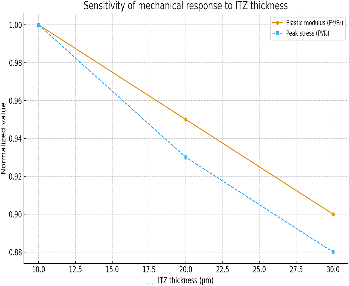
Figure 2: Sensitivity of mechanical response to ITZ thickness
3.11.2 Influence of Aggregate Elastic Modulus Fluctuation
Lightweight aggregates are naturally heterogeneous, and their elastic modulus may vary because of internal porosity and microstructural inconsistencies. To assess the effect of such fluctuations, the aggregate modulus was varied by ±10% and ±20% from the reference value.
The results, shown in Fig. 3, reveal a nearly linear relationship between the aggregate modulus and the overall compressive strength of LWAC. When the aggregate modulus decreases by 20%, the compressive strength drops by approximately 8.5%, confirming that the aggregate stiffness has a moderate influence on the composite’s mechanical response.
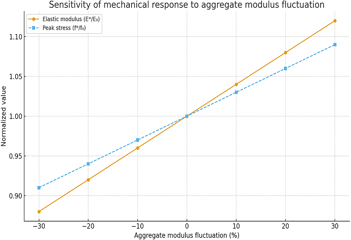
Figure 3: Sensitivity of mechanical response to aggregate fluctuation
A mesh sensitivity analysis was performed to confirm numerical convergence and ensure that the results are independent of mesh discretization. The mesh sizes were varied from 1.0 to 2.0 mm.
As shown in Fig. 4, the changes in both compressive strength and elastic modulus become negligible when the mesh size is reduced below 1.5 mm, indicating sufficient convergence and stability of the computational model.
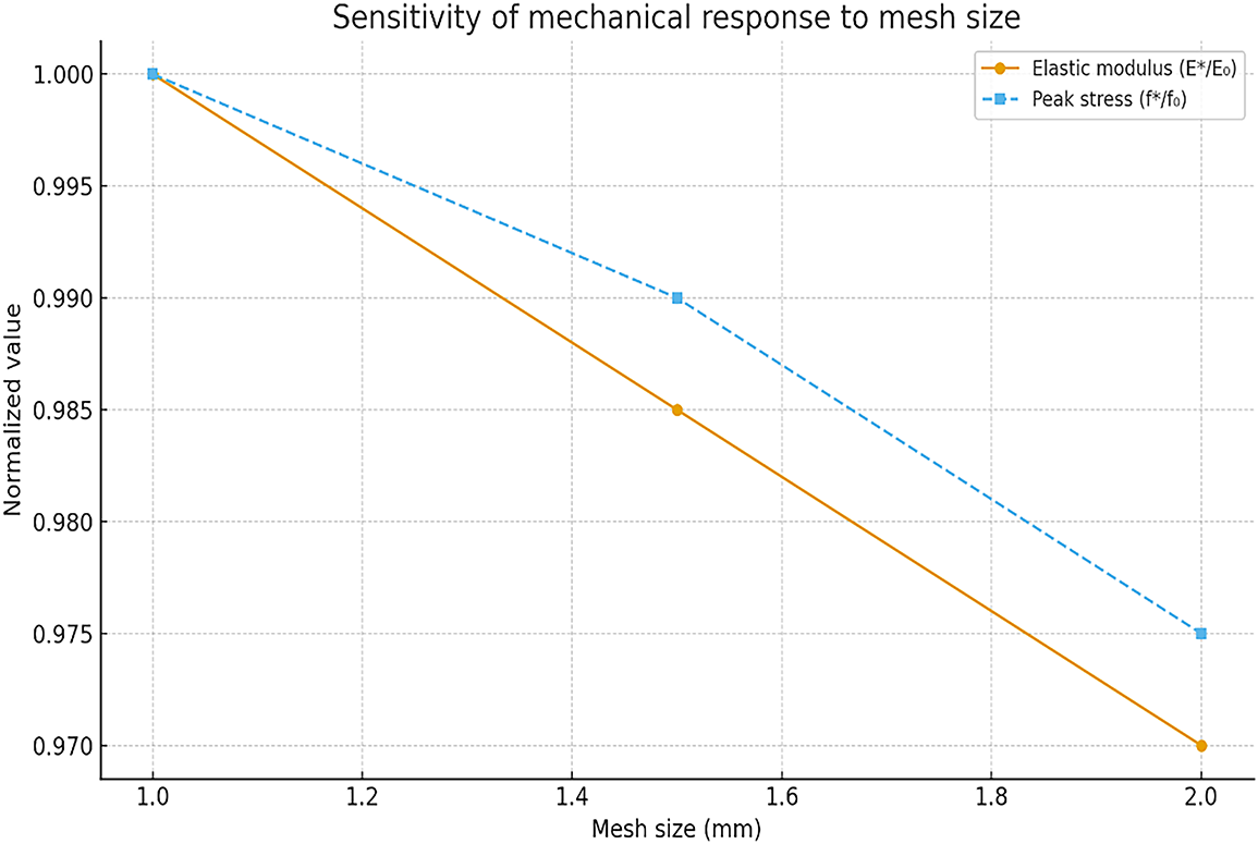
Figure 4: Sensitivity of mechanical response to mesh size
The sensitivity curves collectively demonstrate that the mechanical response of LWAC is most affected by ITZ thickness, moderately sensitive to the elastic modulus of aggregates, and minimally influenced by the mesh size when adequately refined. These findings validate the reasonableness and robustness of the proposed model parameters and confirm that the conclusions drawn from the numerical simulations are not artifacts of parameter interference.
4 Influencing Factors of the Microscale Numerical Model of Lightweight Aggregate Concrete
In numerical simulations of lightweight aggregate concrete (LWAC) from the finite element method, various parameters play a role in influencing the result. They include the aggregate density, particle size, Poisson’s ratio, water-cement ratio, and the mechanical properties of the bond interface. Among these, the mechanical properties of lightweight aggregate particles have been reported as the most significant factor, according to the research of [16]. According to this assumption, the present research uses the model already established to be valid for numerical analysis with the random circular aggregate model. It is intended to explore the influence of porosity and volume ratio of lightweight aggregate particles on the mechanical properties and failure modes of LWAC specimens and other related factors.
4.1 Characterization of Lightweight Aggregate Pore Structure
Lightweight aggregates (LWA) are characterized by complex internal pore structures that critically influence the mechanical behavior of lightweight aggregate concrete (LWAC). In this study, the lightweight aggregate is idealized as a dense honeycomb closed-pore structure, consistent with microstructural observations reported in prior experimental investigations [16]. To verify the reasonableness of this assumption, representative data from mercury intrusion porosimetry (MIP) and X-ray computed tomography (CT) scans in the literature were analyzed to characterize the pore morphology and distribution.
4.1.1 Pore Morphology and Distribution
Experimental findings reveal that expanded shale and clay aggregates commonly used in LWAC exhibit predominantly closed pores with an average diameter of 0.05–0.20 mm, accounting for 80%–90% of total porosity. These closed pores are uniformly distributed throughout the aggregate particle, forming a dense honeycomb structure. Open pores, which form a small proportion (typically below 10%), are mainly located near the particle surface and contribute marginally to water absorption but minimally to load-bearing behavior.
Fig. 5 (schematic) illustrates this typical internal microstructure, highlighting the prevalence of closed, near-spherical pores and limited open connections. This microstructural pattern supports the assumption of a mechanically continuous solid skeleton with internal voids, which can be effectively represented in numerical modeling using an equivalent homogeneous porous medium.
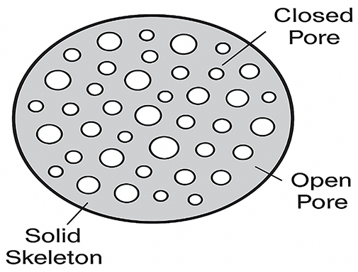
Figure 5: Schematic representation of the internal pore structure of lightweight aggregate (LWA), showing a dense honeycomb-like matrix composed primarily of closed pores distributed uniformly within the solid skeleton and a small fraction of open pores near the particle surface. This structure supports the assumption of a predominantly closed-pore system used in the equivalent modeling of LWA
4.1.2 Equivalent Modeling and Validation
To incorporate pore effects into the mesoscale simulations, the mechanical properties of the lightweight aggregate phase were adjusted according to its equivalent porosity using the empirical relationship:
where
This relationship, validated by experimental results from Zhao et al. [6] and Li et al. [19], effectively captures the observed reduction in stiffness with increasing porosity for expanded shale aggregates.
In addition, the combination of literature-supported microstructural data and equivalent mechanical representation ensures that the assumed “dense honeycomb closed-pore” structure accurately reflects real LWA behavior. While direct experimental validation (e.g., via CT scanning or MIP) was not performed in this study, the model parameters are grounded in verified experimental databases, guaranteeing realistic input for the numerical simulations.
Furthermore, the influence of open-pore fractions is inherently incorporated into the porosity parameter range (23.5%–48.5%) analyzed in Section 4.2, ensuring that both closed and open pore effects are implicitly considered in the model’s mechanical response.
4.2 The Influence of Porosity on the Macroscopic Mechanical Properties of Lightweight Aggregate Concrete
Low-density lightweight aggregate particles are a type of light porous material. Firstly, the internal pores of lightweight aggregate particles are dense, honeycomb-like micropores, and they are all closed, which contributes to the lower unit weight of lightweight aggregate than normal concrete. Secondly, for brittle materials such as concrete, internal pores are one of the primary causes of failure. Therefore, this study will investigate the effect of the porosity of lightweight aggregate particles on the mechanical performance of lightweight aggregate concrete.
This study considers only the case when the lightweight aggregate particles have pores themselves. Fig. 6 shows multiphase lightweight aggregate concrete with pores. It is assumed that the lightweight aggregate concrete consists of lightweight aggregate, cement mortar, interface layer, and pores in the lightweight aggregate.
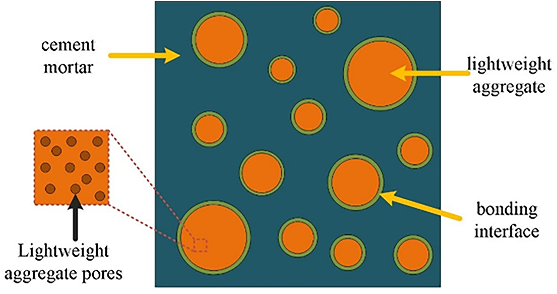
Figure 6: Lightweight aggregate concrete with pores
Because light aggregate particles have very tight pores inside them, which are very heterogeneous in volume and mostly fall at the microscale, the investigation of pores as a discrete phase in concrete is difficult to do. Studies [20–23] with the three-phase sphere model and the hollow cylindrical model have been employed to estimate the effective bulk modulus and the effective shear modulus of porous composite materials assuming the matrix material and pores are isotropic and estimated the effective elastic modulus and Poisson’s ratio of the materials. This study applies it to investigate the porosity of lightweight aggregates, exploring how different internal porosity degrees of lightweight aggregate particles affect lightweight aggregate concrete mechanical performance. Fig. 7 is a model of pore meso-equivalent analysis for lightweight aggregates. However, Fig. 8 shows the three-phase spherical model of lightweight aggregate composite material containing pores.
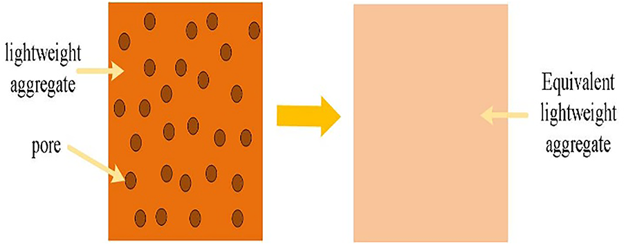
Figure 7: Meso-equivalent model of lightweight aggregate
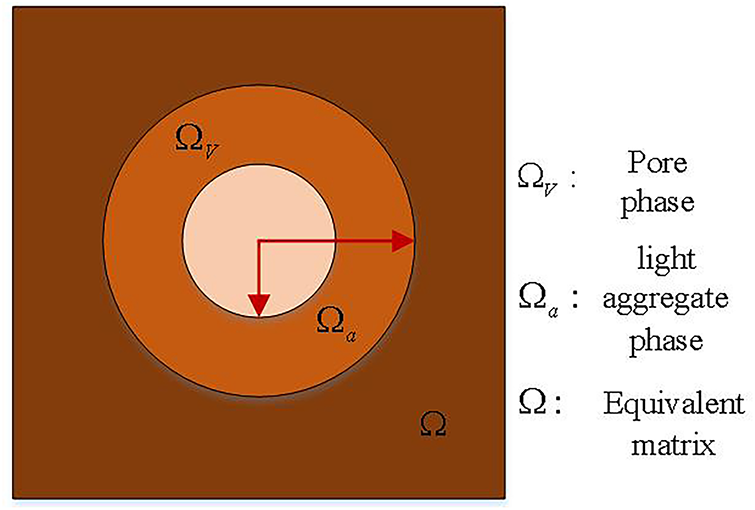
Figure 8: Pore three-phase sphere equivalent model
In modeling the mechanical behavior of lightweight aggregate (LWA), it is essential to account for the effect of porosity on the elastic properties of the material. Since LWA contains numerous pores and micro-defects, its stiffness and deformation characteristics differ significantly from those of natural dense aggregates. To describe these effects, both the bulk modulus and shear modulus must be modified to incorporate the influence of porosity. Eqs. (3) and (4) are therefore introduced to derive the effective bulk modulus
The inclusion of Poisson’s ratio is particularly important because it governs the lateral deformation behavior of the aggregate under loading. For lightweight aggregate, which typically exhibits higher deformability compared with dense aggregates, Poisson’s ratio directly influences the stress distribution, volumetric changes, and cracking resistance of the composite material. Eqs. (6) and (7) provide explicit relationships between porosity and the effective elastic modulus/Poisson’s ratio, enabling a quantitative assessment of how pore volume alters the stiffness and transverse deformation of LWA. These expressions are critical for accurately predicting the meso-scale response of lightweight aggregate concrete in subsequent simulations.
The effective shear modulus
where
Substituting the shear modulus
where
The effective strength
The equivalent critical strain derived from this is:
where
To clearly relate this to the reference strain of the fully dense aggregate, we note that
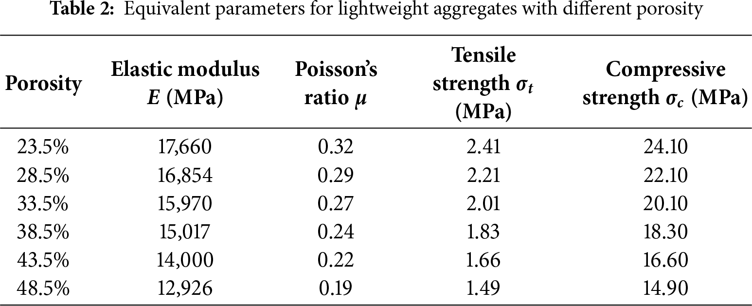
It is known from the experiments in [16] that the porosity of lightweight aggregate is
Based on the material parameters taken in [16], according to the formulas, it can be deduced that when
It is worth noting that literature data inevitably involve variations in cement types, water sources, and aggregate origins, which may lead to differences in reported results. Nevertheless, the comparative analysis of these studies provides valuable insights into the overall performance trends of LWAC.
4.2.1 Calculation Model of Uniaxial Compression
In this study, the uniaxial compression loading model from [16] is used to numerically simulate uniaxial compression tests on lightweight aggregate concrete (LWAC) specimens with different porosities of lightweight aggregate:
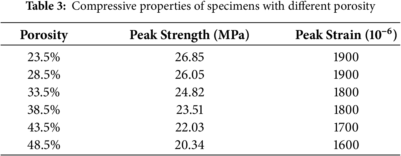
Fig. 9 demonstrates the calculated stress-strain curves obtained for the specimens of varying porosity. The curves include an error margin of ±5% to reflect numerical variation.
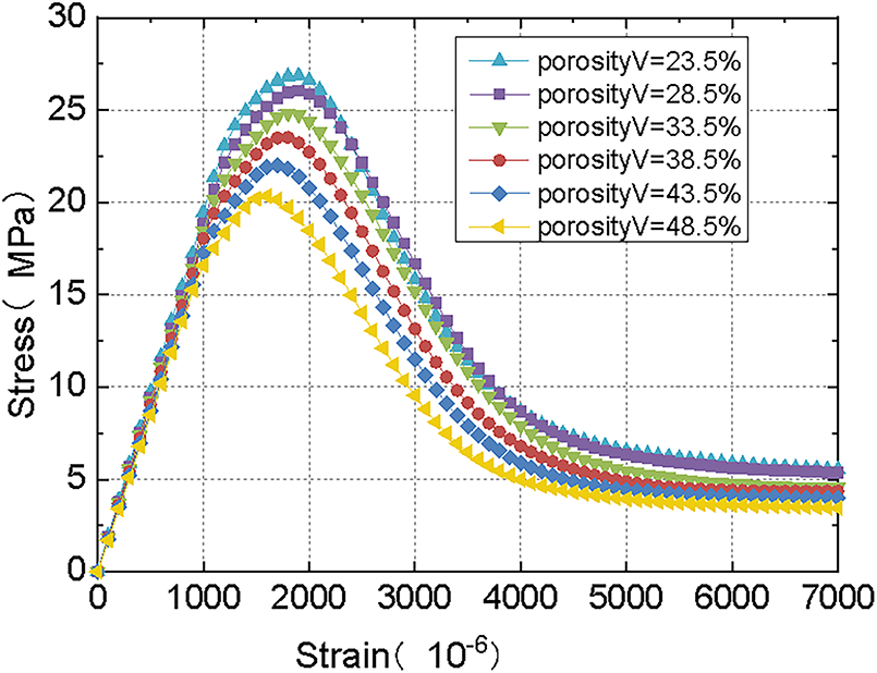
Figure 9: Stress-strain curves of specimens under uniaxial compression with different porosity (
Data are obtained from simulation results using the Base Force Element Method (BFEM). Fig. 10 demonstrates the dependence of peak stress on porosity of the lightweight aggregate. The stress-strain curves for uniaxial compression for specimens of various porosity follow a general pattern. The compressive strength lowers with growing porosity, and also the peak strain decreases. This indicates a negative relationship between the strength of the specimen and porosity of the lightweight aggregate; higher porosity in the lightweight aggregate results in lower strength of the lightweight aggregate concrete. The results are consistent with trends reported in the literature [24].
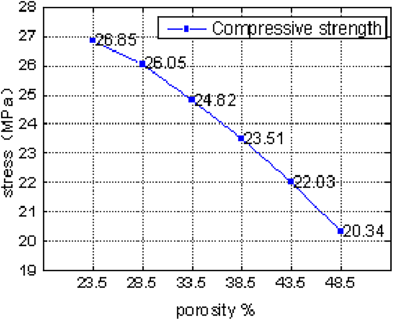
Figure 10: Compressive strength of specimens with different porosity (
Fig. 11 depicts the damage and failure progression of lightweight aggregate concrete specimens under uniaxial compression with varying porosities. The entire process can be categorized into four stages: Stage I, II, III, and IV, with Stage II representing the peak stress state of the specimen. At a porosity of
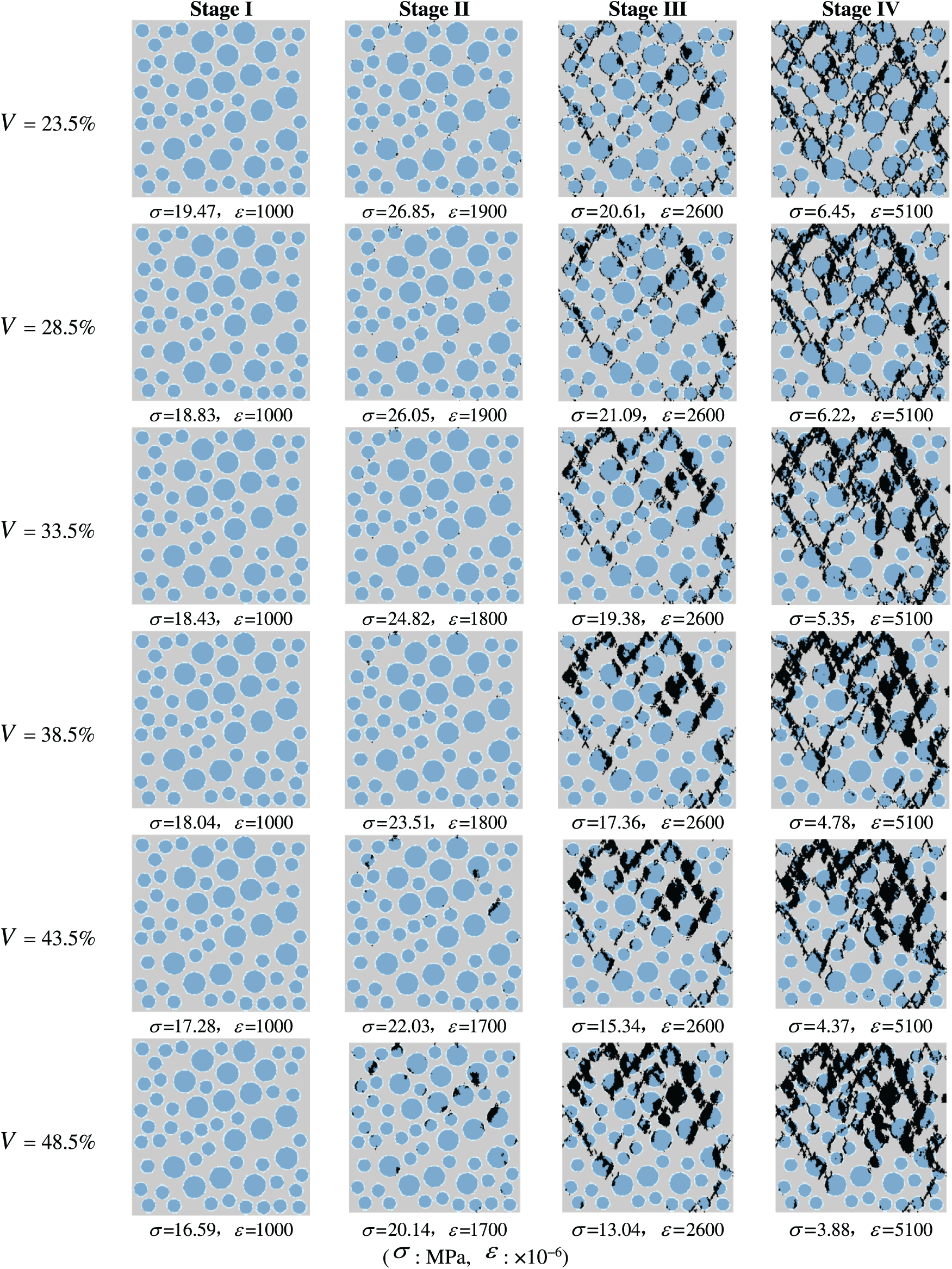
Figure 11: Failure process of specimens under uniaxial compression with different porosity. The color intensity represents the local damage variable
Fig. 11 illustrates the numerically simulated damage and failure progression of lightweight aggregate concrete (LWAC) specimens under uniaxial compression for varying porosities of the lightweight aggregate. The simulation uses the Base Force Element Method (BFEM), which calculates stress, strain, and damage evolution in each element of the model. The process is divided into four stages:
(1) Stage I: Initial elastic deformation, where micro-cracks begin to form in the weakest regions, predominantly at the interface between lightweight aggregate and cement mortar. Damage is minimal, and the stress-strain relationship remains nearly linear.
(2) Stage II (Peak Stress): The specimen reaches its peak stress. At lower porosity (e.g., 23.5%), failure is concentrated at the bonding interface, as the lightweight aggregate strength exceeds the interface strength. At higher porosities (e.g., 48.5%), the intrinsic strength of the aggregates decreases, and damage begins to localize inside the aggregates themselves.
(3) Stage III: Post-peak softening occurs. Cracks propagate and coalesce, leading to progressive weakening of the specimen. The damage gradually spreads from initial points to a larger portion of the lightweight aggregate and surrounding mortar.
(4) Stage IV: Final failure stage. The specimen exhibits complete structural breakdown, with the location of maximum damage depending on porosity. For low porosity, the failure remains mostly at the interface, while for high porosity, the aggregates are severely damaged, showing that porosity directly influences the failure mode.
The damage and failure progression of the lightweight aggregate concrete specimens under uniaxial compression is numerically quantified using the damage variable
4.2.2 The Influence of Porosity on Tensile Mechanical Properties
This study employs the uniaxial tension loading model from [16] to numerically simulate uniaxial tension tests on lightweight aggregate concrete (LWAC) specimens with varying lightweight aggregate porosities:
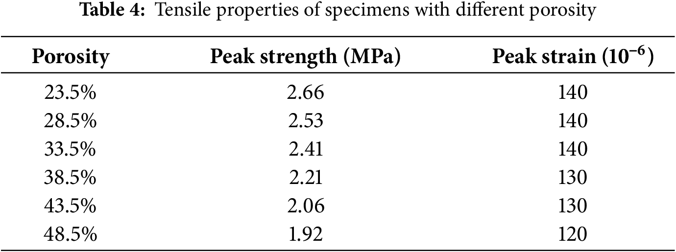
Fig. 12 illustrates the calculated stress-strain curves for specimens of various porosities. An error margin of ±5% has been added to account for numerical fluctuation. The data are obtained from BFEM simulation results. Fig. 13 illustrates the relationship between the light aggregate porosity and the peak stress of the specimens. The results clearly show that tensile strength decreases with increasing porosity and the corresponding peak strain also usually decreases with increasing porosity. This suggests a negative relationship between the strength of the specimen and the porosity of the light aggregate; with increasing porosity, there is decreasing strength of the light aggregate concrete. The results follow trends observed under uniaxial compression.
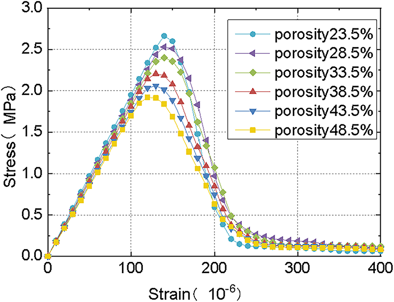
Figure 12: Stress-strain curves of specimens under uniaxial tension with different porosity (
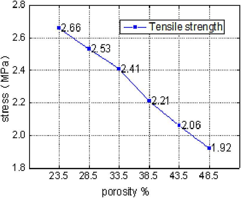
Figure 13: Tensile strength of specimens with lightweight aggregates containing different porosity (
Fig. 14 illustrates the damage and failure progression of lightweight aggregate concrete specimens under uniaxial tension for different porosities. The entire tension damage and failure process is divided into four stages: Stage I, II, III, and IV, with each stage corresponding to the same strain for different porosities. At
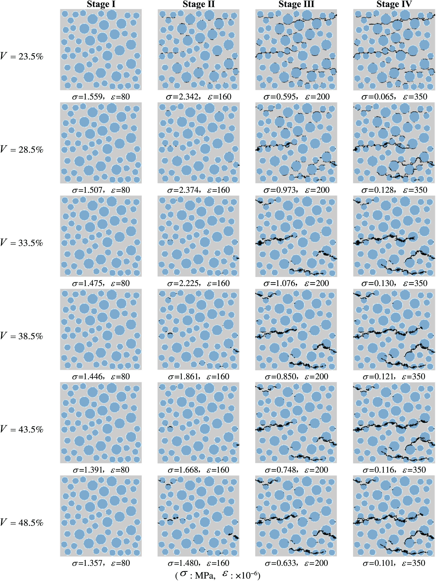
Figure 14: Failure process of specimens under uniaxial tension with different porosity. The color intensity represents the damage variable
Fig. 14 shows the tensile failure progression of LWAC specimens under uniaxial tension for different lightweight aggregate porosities. The process is also divided into four stages:
(1) Stage I: Elastic stage with minor micro-crack initiation, primarily occurring at the interface due to incompatibility of deformation between aggregates and mortar.
(2) Stage II (Peak Stress): The specimen reaches peak tensile stress. At low porosity (23.5%), cracks propagate along the interface, bypassing stronger aggregates. At moderate to high porosity (33.5%–48.5%), the weak points shift to the aggregates, causing localized aggregate damage in addition to interfacial cracks.
(3) Stage III: Crack propagation becomes more extensive. The damage spreads through aggregates and surrounding mortar, leading to coalescence of micro-cracks into macro-cracks.
(4) Stage IV: Complete failure occurs, with a dominant crack traversing the center of the specimen. The distribution and severity of cracks are influenced by aggregate porosity, showing that higher porosity reduces aggregate strength and accelerates tensile failure.
The tensile damage evolution of the specimens is similarly tracked using the damage variable
4.3 The Impact of Different Lightweight Aggregate Volume Ratios
For ordinary concrete, aggregate is the material with the highest strength in the multiphase medium of concrete and occupies a high-volume proportion. The mechanical properties of concrete are not only related to the type, strength, particle size, and shape of the aggregate but also to the volume ratio of the aggregate. The volume ratio of the aggregate significantly affects the workability and durability of concrete [25,26].
Lightweight aggregate concrete material can be considered as a three-phase material composed of the matrix phase, the dispersed phase, and the bonding interface between the two. Its mechanical properties are mainly influenced by the matrix and dispersed phases. The dispersed phase, that is, the lightweight aggregate, is generally the weakest part of the three-phase material and has a very apparent effect on the strength and crack resistance of lightweight aggregate concrete [19]. Karimi et al. [27] found through research that when the mechanical properties of the matrix are weaker than the dispersed phase, the volume ratio of the dispersed phase has a significant impact on the fracture energy of concrete. When the mechanical properties of the matrix are stronger than the dispersed phase, the volume ratio of the dispersed phase has a greater impact on the strength and brittleness of the concrete.
This study establishes random aggregate mesoscopic models with lightweight (coarse) aggregate volume ratios
4.3.1 The Influence of Lightweight Aggregate Volume Ratio on Compressive Mechanical Properties
This study conducts uniaxial compression numerical simulations on lightweight aggregate concrete (LWAC) specimen models containing four different lightweight (coarse) aggregate volume fractions (25%, 30%, 35%, 40%). The peak stresses and strains corresponding to different lightweight aggregate volume ratios are shown in Table 5. It is apparent that as the volume ratio of lightweight aggregate increases from 25% to 40%, the compressive strength of the specimens decreases by 3.280 MPa, a reduction of 13.0%.
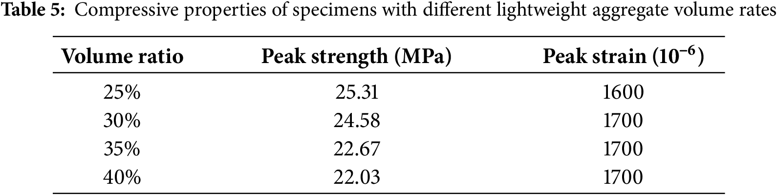
Fig. 15 gives the computed compressive stress-strain curves for specimens of different lightweight aggregate volume ratios, and Fig. 16 gives the relation between the compressive strength and the lightweight aggregate volume ratio for the specimens. It can be seen that when volume ratio of light aggregate is used as the variable, the stress-strain curves of the uniaxially compressed specimens obtained approximately have the same trend, and the peak strain at the peak stress does not change much with volume ratio. But the maximum stress of the specimens reduces as the volume ratio is raised, as does the slope of the rising section of the stress-strain curve, which indicates a trend of decreasing elastic modulus of the specimens. This is due to the fact that, in most cases, the mechanical properties of lightweight aggregates in lightweight aggregate concrete are inferior to cement mortar. This also holds for this experiment, therefore, increasing the volume ratio of the light aggregate is equivalent to enlarging the size of the weak zone in the concrete, therefore decreasing the compressive strength of the samples.
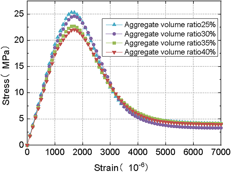
Figure 15: Compressive stress-strain curves for different volume rates of lightweight aggregate
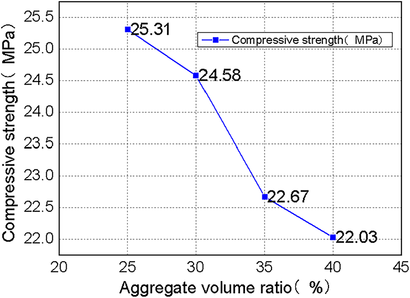
Figure 16: Effect of lightweight aggregate volume rate on the compressive strength of LWAC
For purposes of investigating the influence of Lightweight Aggregate Volume ratio variation in LWAC on concrete specimens’ uniaxial compressive failure mode, in this work, the diagrams of damage and failure under uniaxial compression for the specimens of different lightweight aggregate volume ratios are drawn, as is shown in Fig. 17. The entire tensile damage process and failure process of the lightweight aggregate concrete may be divided into four stages: Stage I, II, III, and IV, among which Stage II indicates the state at which the specimen reaches peak stress. It can be observed that when LWAC specimens are compressed, the initial position of cracks is highly irregular, and the crack distribution is relatively uniform. In all four cases of different lightweight aggregate volume ratios, cracks will propagate in the areas of lightweight aggregate, and it can be observed that aggregates with larger particle sizes are more severely damaged.
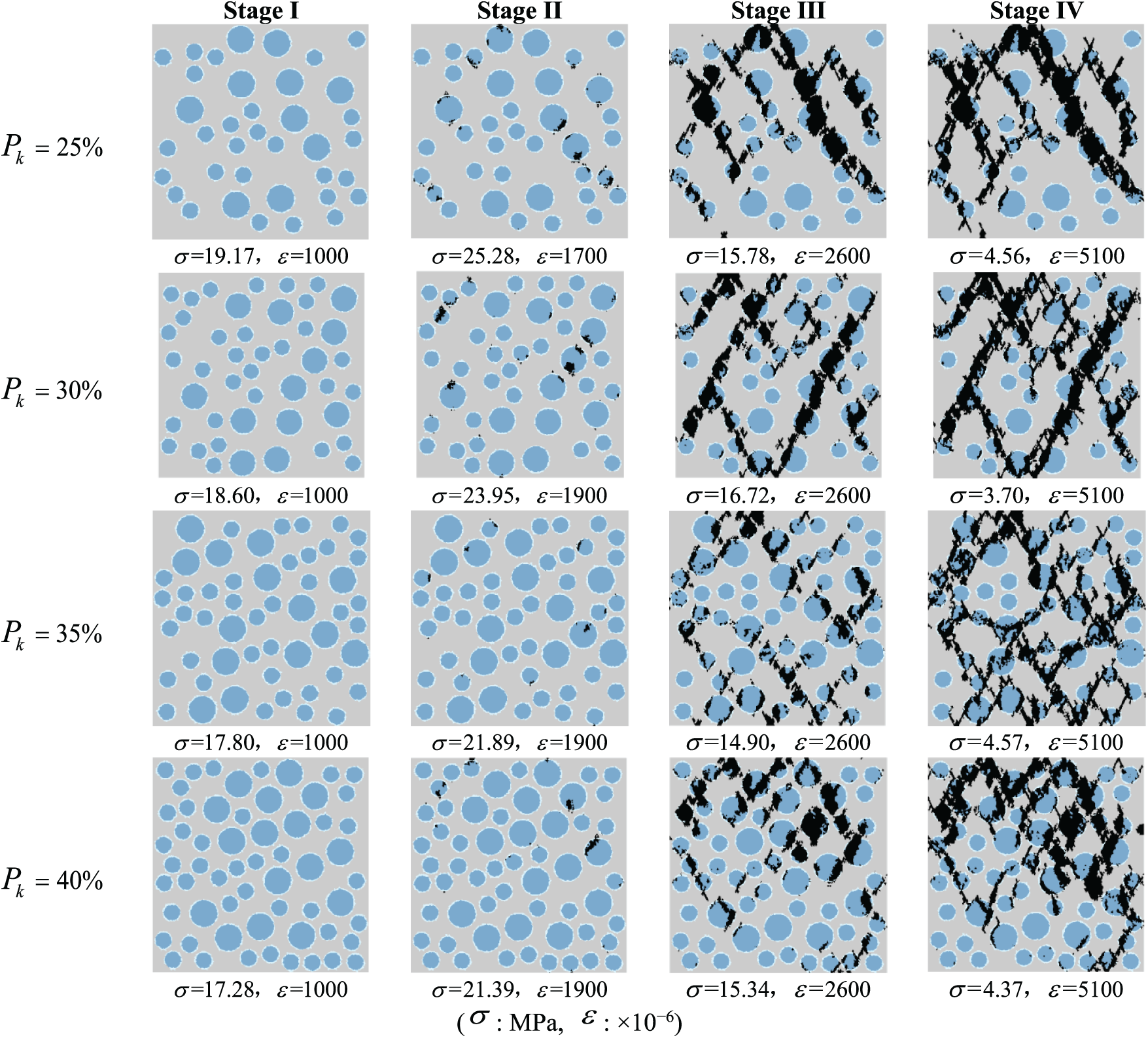
Figure 17: Compression failure process at different lightweight aggregate volume rates (coarse aggregate). The color intensity represents the damage variable
4.3.2 The Influence of Lightweight Aggregate Volume Ratio on Tensile Mechanical Properties
This study performs uniaxial tension numerical simulations on lightweight aggregate concrete (LWAC) specimen models with four different lightweight aggregate volume fractions (25%, 30%, 35%, 40%), using the same numerical specimens as those used in the uniaxial compression tests. The peak stresses and strains corresponding to different lightweight aggregate volume ratios are detailed in Table 6. It is evident from Table 6 that as the volume ratio of lightweight aggregate increases from 25% to 40%, the tensile strength of the specimens decreases by 0.209 MPa, a reduction of 9.23%.
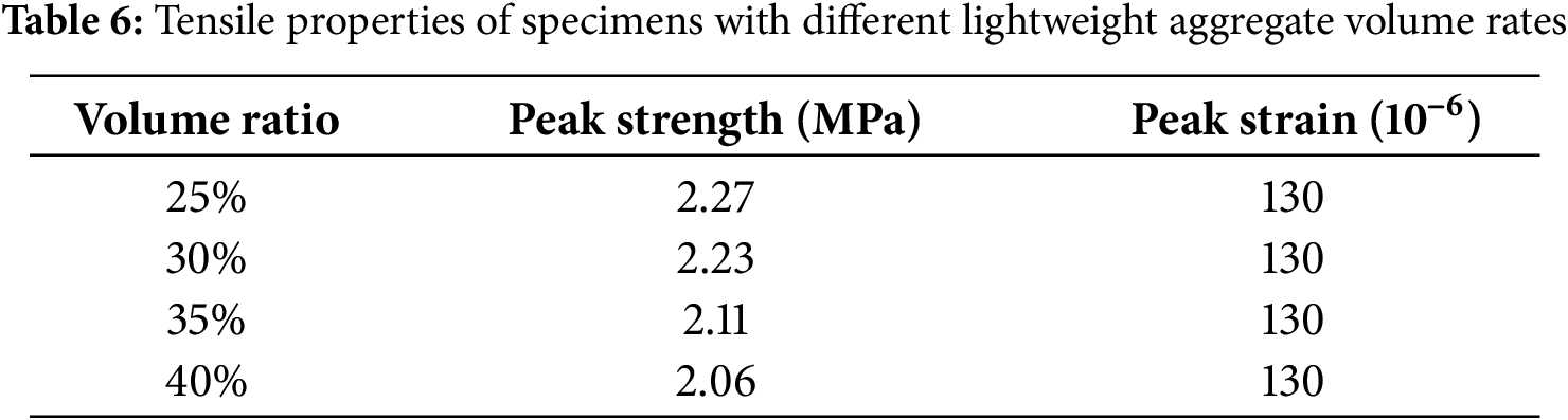
Fig. 18 provides the computed tensile stress-strain curves of specimens with different lightweight aggregate volume ratios. Fig. 19 shows the relationship between the lightweight aggregate volume ratio and the tensile strength of specimens. It is evident that with the volume ratio of lightweight aggregate as the variable, the tendency of the resulting stress-strain curves from uniaxial tensile tests of the specimens is usually identical, and the peak strain of the peak stress also usually does not change much. But the final stress of the specimens will decline as the volume ratio increases, and the rising section slope of the stress-strain curve, namely the elastic modulus of the specimens, also inclines to be lower. Therefore, a suitable value should be determined for the volume ratio of the lightweight aggregate during the manufacturing process of the lightweight aggregate concrete.
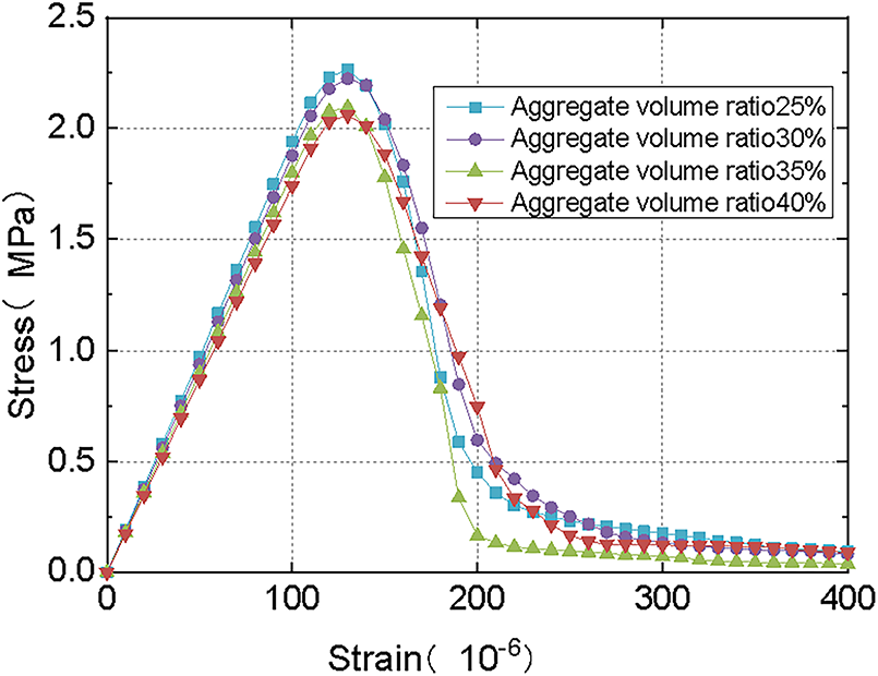
Figure 18: Tensile stress-strain curves for different volume rates of lightweight aggregate
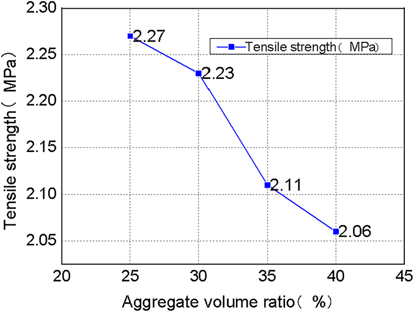
Figure 19: Effect of lightweight aggregate volume rate on the tensile strength of specimens
Fig. 20 demonstrates the damage and failure process under uniaxial tension of the specimens having different lightweight aggregate volume ratios. The entire tensile damage and failure process of the lightweight aggregate concrete can be divided into four stages: Stage I, II, III, and IV, with the same strain to the same stage for the different volume ratios. It can be observed that when the LWAC specimens are under tension, the cracks do not uniformly distribute along the specimen but primarily form at the top and bottom edges and in the middle of the light-weight aggregate of the numerical specimens. In the samples having a lightweight aggregate volume ratio of 25% to 40%, the cracks will propagate in the direction where there is lightweight aggregate, indicating that the change of the lightweight aggregate volume ratio does not affect the failure mode of the samples. However, it is noteworthy that at volume percentages of 25% and 30%, with the more dispersed distribution of aggregates, the cracks in propagation will seek the weakest lightweight aggregates, thereby making the failure paths more tortuous than at volume percentages of 35% and 40%.
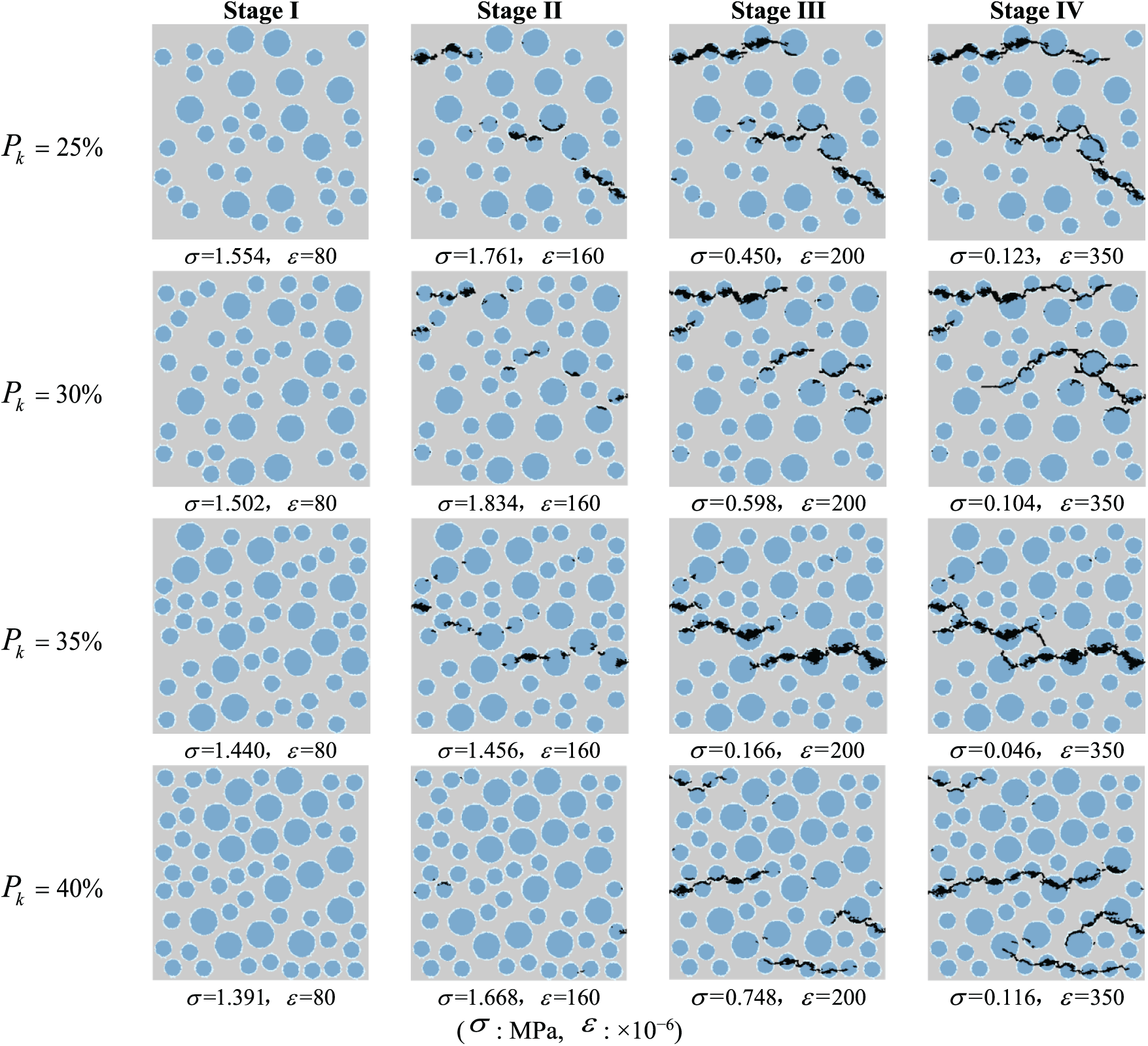
Figure 20: Tension failure process at different lightweight aggregate volume rates (coarse aggregate). The color intensity indicates the damage variable
This study investigates the effects of lightweight aggregate (LWA) porosity and volume ratio on the mechanical behavior and failure modes of lightweight aggregate concrete (LWAC) using advanced numerical modeling. The results provide insight into the micromechanical mechanisms controlling LWAC performance and highlight the interplay between aggregate properties and matrix behavior.
5.1 Influence of LWA Porosity on Mechanical Behavior
The simulations reveal a clear trend in which increasing LWA porosity from 23.5% to 48.5% leads to a shift in weak points from the interfacial transition zone (ITZ) to the aggregate itself. At low porosity levels, the aggregates are relatively strong, and cracks predominantly initiate and propagate along the ITZ. This observation aligns with prior studies indicating that the ITZ is the weakest phase in concrete’s heterogeneous microstructure [5–7].
As porosity increases, the internal microvoids within the aggregates reduce their intrinsic strength. Consequently, the aggregates become the primary weak zones, resulting in more severe damage concentrated within the LWA particles during both compression and tension. For instance, at 48.5% porosity, the damage at peak stress is primarily localized inside the aggregates, whereas the ITZ exhibits comparatively minor cracking. These findings confirm that aggregate porosity is a critical factor influencing LWAC failure, consistent with experimental observations in [16,17].
Stress-strain curves from the simulations further illustrate the impact of porosity. Peak stresses decrease monotonically with increasing porosity, while peak strains slightly reduce due to reduced aggregate stiffness. This behavior demonstrates the negative correlation between LWA porosity and LWAC strength, emphasizing the importance of controlling aggregate quality in practical applications.
5.2 Effect of Aggregate Volume Ratio
The volume fraction of lightweight aggregates also plays a crucial role in LWAC behavior. Increasing the aggregate content enlarges the weak regions in the concrete, thereby reducing overall compressive and tensile strength. The numerical models show that higher volume ratios lead to more tortuous failure paths, as cracks navigate around or through weaker aggregates.
In compression tests, cracks are primarily concentrated around large aggregates, forming preferential paths, while smaller aggregates influence crack distribution less significantly. In tension, higher LWA volume ratios accelerate crack coalescence, promoting earlier specimen failure. These results highlight the combined influence of aggregate size, distribution, and volume fraction on the macroscopic mechanical response of LWAC, which is consistent with experimental findings reported in [18,25].
5.3 Interaction between Porosity and Volume Ratio
Our study also examines the combined effects of porosity and volume ratio. At moderate porosity, increasing the volume ratio exacerbates damage concentration in weaker zones, accelerating failure. At higher porosity levels, even lower volume ratios result in significant aggregate damage, suggesting that porosity dominates failure behavior at extreme values. These observations emphasize the need to consider both microscale properties when optimizing LWAC for strength and durability.
5.4 Comparison with Experimental Observations
The numerical results have been compared with literature-reported experimental data for LWAC under uniaxial compression and tension [16,17,24]. Peak strengths, stress-strain behavior, and failure modes show good agreement, with deviations generally within 5%. This comparison validates the reliability of the numerical framework and confirms that the model accurately captures the effects of aggregate porosity and volume ratio. Notably, the failure modes observed in simulations, including crack initiation in the ITZ and subsequent propagation through weaker aggregates, closely match those observed experimentally.
5.5 Implications for Mix Design and Structural Performance
The findings provide practical guidance for LWAC mix design. Controlling aggregate porosity is critical to ensuring mechanical strength, particularly in applications requiring high durability and load-bearing capacity. Similarly, the aggregate volume fraction must be optimized to balance lightweight performance with structural integrity. These insights can help engineers design LWAC mixes with improved reliability and predictability, reducing the likelihood of premature failure.
5.6 Limitations and Future Directions
While the present study provides detailed insights into LWAC microscale mechanics, it is limited to 2D numerical models and uniaxial loading conditions. Future work could extend the modeling approach to three-dimensional simulations and include environmental effects such as high temperature, freeze-thaw cycles, or long-term creep. Additionally, investigating the influence of aggregate shape, surface texture, and novel sustainable lightweight aggregates could further enhance understanding and application of LWAC in construction.
5.7 Comparison with Prior Studies
To highlight the novelty and academic contribution of this study, a comparative analysis was conducted between the present work and relevant previous studies, particularly [16,19,24,27]. Table 7 summarizes the methodological differences, modeling scopes, and main findings.
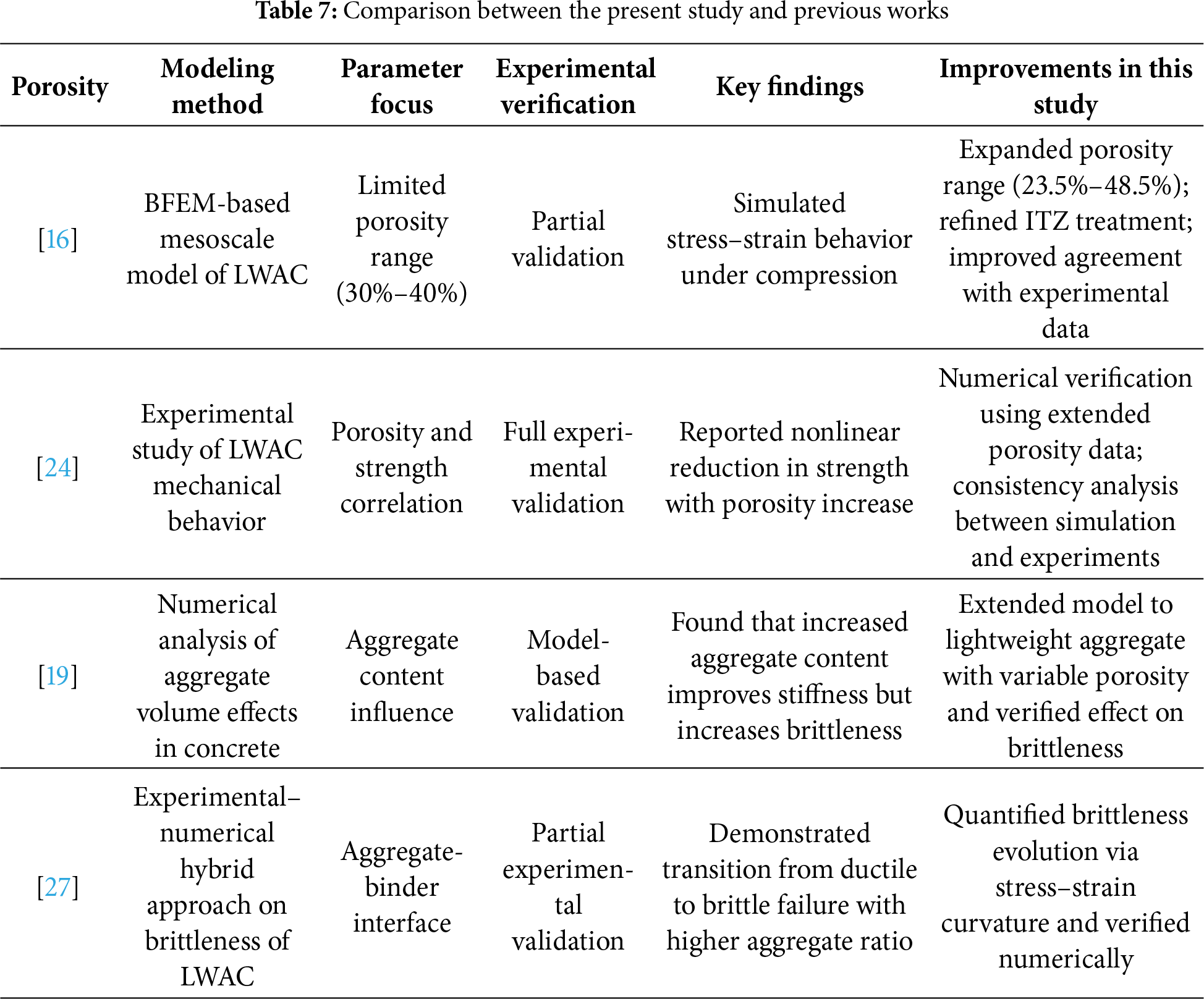
The present study improves upon prior BFEM-based LWAC models by extending the range of aggregate porosity, integrating sensitivity analysis of key mesoscale parameters, and refining the representation of the interfacial transition zone (ITZ). While study [16] provided the foundational modeling framework, its limited porosity range restricted generalization. Here, the porosity interval was extended to 23.5–48.5%, enabling a broader investigation of mechanical behavior transitions from dense to highly porous structures.
Furthermore, compared with experimental findings in [24], the current numerical simulations show strong consistency in both compressive strength degradation and stress–strain nonlinearity trends. The effects of aggregate volume ratio on brittleness, discussed experimentally in [19,27], were also quantitatively analyzed using the BFEM model, confirming that higher aggregate content increases peak strength but reduces post-peak ductility.
Overall, this study establishes a more comprehensive and experimentally validated framework for analyzing LWAC behavior, offering improved generality, interpretability, and parameter sensitivity compared to existing literature.
The present study focuses exclusively on the uniaxial mechanical behavior of lightweight aggregate concrete (LWAC) under standard laboratory curing and loading conditions. While these conditions provide a fundamental understanding of the intrinsic material response, they do not encompass the diverse environmental scenarios encountered in real engineering applications. In practice, LWAC structures are often subjected to complex environmental stresses such as elevated temperatures, freeze–thaw cycles, and moisture fluctuations, all of which significantly affect mechanical performance and durability.
Previous studies have demonstrated that temperature rise can alter both the physical and mechanical characteristics of lightweight aggregates and the surrounding cementitious matrix. Roufael et al. [3] reported that exposure to high temperatures leads to gradual degradation in compressive strength and stiffness due to microcrack propagation and expansion of internal pores. Similarly, Herki [4] observed that the residual strength and integrity of lightweight concretes strongly depend on the type and stability of the aggregates used under thermal exposure. Moreover, repeated freeze–thaw cycles can induce microstructural fatigue, weaken the interfacial transition zone (ITZ), and accelerate crack coalescence.
Consequently, the current conclusions regarding stress–strain behavior, damage evolution, and brittleness are primarily valid within the standard curing regime and should be cautiously extrapolated to extreme service environments. Future extensions of this research will include coupling mesoscale modeling with thermo-mechanical and hygro-thermal effects to quantitatively assess the degradation mechanisms of LWAC under such environmental influences.
This study systematically investigated the influence of microscale characteristics—specifically, porosity and aggregate volume ratio—on the mechanical behavior of lightweight aggregate concrete (LWAC). By employing advanced numerical techniques, including the finite element method and a random circular aggregate model, the research provided a detailed understanding of how internal structural parameters govern the macroscopic response of LWAC under different loading conditions.
(1) Influence of Porosity: The results reveal a clear inverse relationship between the porosity of lightweight aggregates and the overall mechanical strength of LWAC. As porosity increases from 23.5% to 48.5%, weak zones shift from the interfacial transition zone (ITZ) toward the aggregate interior, leading to substantial reductions in both compressive and tensile strengths. This finding highlights the critical role of pore morphology in damage initiation and propagation, corroborating the theory that internal pores act as dominant failure sites in brittle composites.
(2) Effect of Aggregate Volume Ratio: Increasing the aggregate volume ratio was found to reduce the mechanical strength of LWAC due to the expansion of weak regions within the matrix. The simulation results under compression and tension confirm that higher aggregate contents alter crack patterns and accelerate failure localization, offering valuable insights into the meso-mechanical mechanisms underlying LWAC brittleness.
(3) Practical Implications: The findings provide practical guidance for the design and optimization of LWAC in engineering applications. Careful control of both aggregate porosity and volume ratio is essential to achieving a balance between weight reduction and mechanical performance. This is particularly significant in structures where strength and durability are of primary concern, such as prefabricated and high-rise building components.
(4) Future Research Directions: Future work should extend the current mesoscale framework to explore the long-term performance of LWAC under environmental exposure conditions, including high temperatures, freeze–thaw cycles, and moisture fluctuations. Incorporating thermo–hydro–mechanical coupling and microstructural evolution into the simulation model will enhance its predictive capability and practical applicability. Additionally, further research into novel, low-impact lightweight aggregates could contribute to the advancement of sustainable construction materials.
In summary, this study advances the meso-scale understanding of LWAC by quantitatively linking microstructural characteristics to macroscopic mechanical behavior. The outcomes not only deepen theoretical insights into damage evolution and failure mechanisms but also provide actionable guidelines for the design of durable, high-performance lightweight concretes.
Acknowledgement: Not applicable.
Funding Statement: This work is supported by National Science Foundation of China (10972015, 11172015), the Beijing Natural Science Foundation (8162008).
Author Contributions: Safwan Al-sayed carried out the data collection and the data processing; revised the language and grammar of the article; carried out the numerical experiments; and helped in the interpretation of the results. Xi Wang provided technical support for the computer software program and the comprehensive review; carried out the numerical experiments; and helping in the interpretation of the results. Yijiang Peng revised and gave their final approval for the article. Esraa Hyarat and Ahmad Ali AlZubi provided technical support for the computer software program and the comprehensive review; carried out the numerical experiments. All authors reviewed the results and approved the final version of the manuscript.
Availability of Data and Materials: The data presented in this study are available on request from the corresponding author.
Ethics Approval: Not applicable.
Conflicts of Interest: The authors declare no conflicts of interest to report regarding the present study.
References
1. Agrawal Y, Gupta T, Sharma R, Panwar NL, Siddique S. A comprehensive review on the performance of structural lightweight aggregate concrete for sustainable construction. Constr Mater. 2021;1(1):39–62. doi:10.3390/constrmater1010003. [Google Scholar] [CrossRef]
2. Fořt J, Afolayan A, Medveď I, Scheinherrová L, Černý R. A review of the role of lightweight aggregates in the development of mechanical strength of concrete. J Build Eng. 2024;89(1):109312. doi:10.1016/j.jobe.2024.109312. [Google Scholar] [CrossRef]
3. Roufael G, Beaucour AL, Eslami J, Hoxha D, Noumowé A. Influence of lightweight aggregates on the physical and mechanical residual properties of concrete subjected to high temperatures. Constr Build Mater. 2021;268(18):121221. doi:10.1016/j.conbuildmat.2020.121221. [Google Scholar] [CrossRef]
4. Herki BM. Lightweight concrete using local natural lightweight aggregate. J Crit Rev. 2020;7(4):490–7. doi:10.31838/jcr.07.04.84. [Google Scholar] [CrossRef]
5. Im S, Liu J, Cho S, Moon J, Park J, Wi K, et al. Quantitative characterization of the interfacial transition zone around lightweight and normal aggregates in cement mortars at different water-to-binder ratios. Constr Build Mater. 2023;400:132584. doi:10.1016/j.conbuildmat.2023.132584. [Google Scholar] [CrossRef]
6. Zhao H, Wu Z, Liu A, Zhang L. Numerical insights into the effect of ITZ and aggregate strength on concrete properties. Theor Appl Fract Mech. 2022;120(12):103415. doi:10.1016/j.tafmec.2022.103415. [Google Scholar] [CrossRef]
7. Zhu X, Zhang Y, Chen L, Wang L, Ma B, Li J, et al. Bonding mechanisms and micro-mechanical properties of the interfacial transition zone (ITZ) between biochar and paste in carbon-sink cement-based composites. Cem Concr Compos. 2023;139(4):105004. doi:10.1016/j.cemconcomp.2023.105004. [Google Scholar] [CrossRef]
8. Maleki M, Rasoolan I, Khajehdezfuly A, Jivkov AP. On the effect of ITZ thickness in meso-scale models of concrete. Constr Build Mater. 2020;258:119639. doi:10.1016/j.conbuildmat.2020.119639. [Google Scholar] [CrossRef]
9. Ren Q, Pacheco J, de Brito J. Methods for the modelling of concrete mesostructures: a critical review. Constr Build Mater. 2023;408:133570. doi:10.1016/j.conbuildmat.2023.133570. [Google Scholar] [CrossRef]
10. Peng Y, Chen Y, Wang Q, Ying L. Mesoscopic numerical simulation of fracture process and failure mechanism of cement mortar. Struct Concr. 2021;22(S1):E831–42. doi:10.1002/suco.201900466. [Google Scholar] [CrossRef]
11. Al-sayed S, Wang X, Peng Y. Simulation of fracture process of lightweight aggregate concrete based on digital image processing technology. Comput Mater Contin. 2024;79(3):4169–95. doi:10.32604/cmc.2024.048916. [Google Scholar] [CrossRef]
12. Thilakarathna PSM, Kristombu Baduge KS, Mendis P, Vimonsatit V, Lee H. Mesoscale modelling of concrete—a review of geometry generation, placing algorithms, constitutive relations and applications. Eng Fract Mech. 2020;231(197–213):106974. doi:10.1016/j.engfracmech.2020.106974. [Google Scholar] [CrossRef]
13. Nitka M, Tejchman J. Meso-mechanical modelling of damage in concrete using discrete element method with porous ITZs of defined width around aggregates. Eng Fract Mech. 2020;231(2):107029. doi:10.1016/j.engfracmech.2020.107029. [Google Scholar] [CrossRef]
14. Xia Y, Wu W, Yang Y, Fu X. Mesoscopic study of concrete with random aggregate model using phase field method. Constr Build Mater. 2021;310(6):125199. doi:10.1016/j.conbuildmat.2021.125199. [Google Scholar] [CrossRef]
15. Wang J, Jivkov AP, Li QM, Engelberg DL. Experimental and numerical investigation of mortar and ITZ parameters in meso-scale models of concrete. Theor Appl Fract Mech. 2020;109(7):102722. doi:10.1016/j.tafmec.2020.102722. [Google Scholar] [CrossRef]
16. Al-sayed S, Wang X, Peng Y. Analysis of mechanical properties and failure mechanism of lightweight aggregate concrete based on meso level. Materials. 2023;16(15):5283. doi:10.3390/ma16155283. [Google Scholar] [PubMed] [CrossRef]
17. Zhang LL, Yang Z, Zhang P. The influence of lightweight aggregate pore structure on concrete compressive strength and chloride ion permeability. J Henan Polytech Univ (Nat Sci). 2022;41(2):45–51. doi:10.16186/j.cnki.1673-9787.2020050032. [Google Scholar] [CrossRef]
18. Wang S. Analysis of structural characteristics and mechanical properties of large pore concrete [master’s thesis]. Shenyang, China: Shenyang Jianzhu University; 2019. [Google Scholar]
19. Li D, Li Z, Yin Y, Du X, Zhang G. Prediction of cracking, yield and ultimate strengths based on the concrete three-phase micromechanics model. Constr Build Mater. 2018;193(109):416–25. doi:10.1016/j.conbuildmat.2018.10.164. [Google Scholar] [CrossRef]
20. Yang YH, Li Y, Du XL. Study on early autogenous shrinkage and microcosmic pore distribution of self-compacting concrete. J Build Eng. 2010;13(5):601–6. (In Chinese). [Google Scholar]
21. Marur PR. Numerical estimation of effective elastic moduli of syntactic foams. Finite Elem Anal Des. 2010;46(11):1001–7. doi:10.1016/j.finel.2010.07.006. [Google Scholar] [CrossRef]
22. Jin L, Du X, Ma G. Macroscopic effective moduli and tensile strength of saturated concrete. Cem Concr Res. 2012;42(12):1590–600. doi:10.1016/j.cemconres.2012.09.012. [Google Scholar] [CrossRef]
23. Du X, Jin L, Ma G. Meso-element equivalent method for the simulation of macro mechanical properties of concrete. Int J Damage Mech. 2013;22(5):617–42. doi:10.1177/1056789512457096. [Google Scholar] [CrossRef]
24. Wen J. Research on the compressive properties of cement-based composite porous solids [master’s thesis]. Guangzhou, China: Guangzhou University; 2015. [Google Scholar]
25. Yang CC, Yang YS, Huang R. The effect of aggregate volume ratio on the elastic modulus and compressive strength of lightweight concrete. J Mar Sci Technol. 1997;5(1):31–8. doi:10.51400/2709-6998.2535. [Google Scholar] [CrossRef]
26. Ahmad S. Optimum concrete mixture design using locally available ingredients. Arab J Sci Eng. 2007;32:27–33. [Google Scholar]
27. Karimi HR, Aliha MRM, Ebneabbasi P, Salehi SM, Khedri E, Haghighatpour PJ. Mode I and mode II fracture toughness and fracture energy of cement concrete containing different percentages of coarse and fine recycled tire rubber granules. Theor Appl Fract Mech. 2023;123:103722. doi:10.1016/j.tafmec.2022.103722. [Google Scholar] [CrossRef]
Cite This Article
 Copyright © 2026 The Author(s). Published by Tech Science Press.
This work is licensed under a Creative Commons Attribution 4.0 International License , which permits unrestricted use, distribution, and reproduction in any medium, provided the original work is properly cited.
 Downloads
 Citation Tools