
 Submit a Paper
 Propose a Special lssue
 Open Access
ARTICLE
Maximum Power Extraction Control Algorithm for Hybrid Renewable Energy System
Electrical Engineering Department, College of Engineering at Wadi Aldawasir, Prince Sattam Bin Abdulaziz University, Wadi Aldawasir, 11991, Saudi Arabia
* Corresponding Author: N. Kanagaraj. Email:
Computer Systems Science and Engineering 2023, 45(1), 769-784. https://doi.org/10.32604/csse.2023.029457
Received 03 March 2022; Accepted 14 April 2022; Issue published 16 August 2022
 View Full Text
 Download PDF
Abstract
In this research, a modified fractional order proportional integral derivate (FOPID) control method is proposed for the photovoltaic (PV) and thermoelectric generator (TEG) combined hybrid renewable energy system. The faster tracking and steady-state output are aimed at the suggested maximum power point tracking (MPPT) control technique. The derivative order number (µ) value in the improved FOPID (also known as PIλDµ) control structure will be dynamically updated utilizing the value of change in PV array voltage output. During the transient, the value of µ is changeable; it’s one at the start and after reaching the maximum power point (MPP), allowing for strong tracking characteristics. TEG will use the freely available waste thermal energy created surrounding the PV array for additional power generation, increasing the system’s energy conversion efficiency. A high-gain DC-DC converter circuit is included in the system to maintain a high amplitude DC input voltage to the inverter circuit. The proposed approach’s performance was investigated using an extensive MATLAB software simulation and validated by comparing findings with the perturbation and observation (P&O) type MPPT control method. The study results demonstrate that the FOPID controller-based MPPT control outperforms the P&O method in harvesting the maximum power achievable from the PV-TEG hybrid source. There is also a better control action and a faster response.Keywords
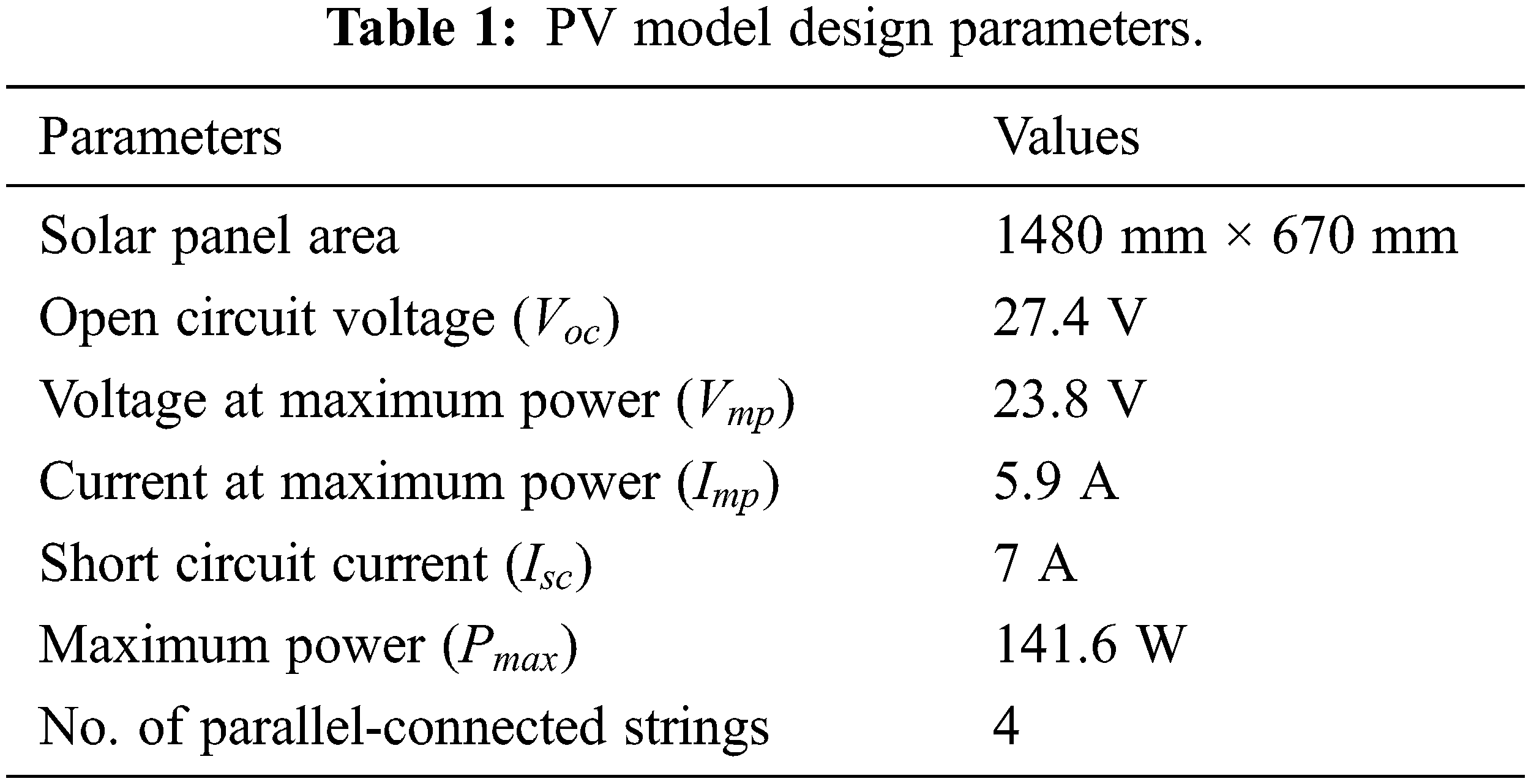
The utilization of renewable energy for electricity generation has increased significantly in recent years across the world due to increasing concern about environmental issues. As it is well known, energy obtained from natural resources will not pollute the environment much and will be supportive of the ecosystem. On the other hand, the cost of electricity generation from renewable energy sources is reasonably costlier when compared to fossil fuel-based generation [1–3]. Also, the energy conversion efficiency of renewable sources-based systems is considerably low when compared to conventional methods [4–6]. Among the numerous types of renewable sources, photovoltaic (PV)-based electricity generation is one of the best and most widely accepted in recent years [7–9]. Even in solar PV systems, a large amount of solar radiation energy is wasted in the form of heat energy, which leads to low energy conversion efficiency [10,11]. Recent research studies have reported the various methods of improving the efficiency of the PV system [12–15]. Extracting the maximum power from the PV cells by the maximum power point tracking (MPPT) control technique is one of the simple and easiest ways to obtain better efficiency. In the MPPT control technique, the possible maximum power will be harvested continuously from the source under different working conditions.
For several years, classical proportional and integral (PI) or proportional, integral and derivative (PID) controllers have been widely used in control applications because of advantages like easy implementation and simple design procedures [16]. However, the performance of classical controllers is not satisfactory, particularly for highly non-linear systems like PV [17,18]. So, it is important to enhance their robustness and quality. Thus, an alternative to classical control is prepared which is known as fractional-order control. The integral and derivative terms of the classical PID controller are modified into non-integer terms with two additional parameters (λ and µ). So, the fractional order proportional integral derivate (PIλDµ) controller will have two extra tuning parameters by which robustness and better controller performance could be achieved specifically for non-linear and complex systems [19–21].
Thermoelectric generators (TEG) have been used widely to convert unused waste thermal energy into electrical voltage in recent years. Applications of the TEG have been reported in various fields from the latest literature [22–26]. TEGs are constructed with many parallel and series-connected thermoelectric elements (TEEs) based on the voltage and power rating. Further, the TEG can also be combined with a solar PV panel to convert the waste thermal energy developed in the PV panel into a useful electric voltage [5,27,28]. The PV-TEG combined hybrid energy systems provide better energy efficiency than the standalone PV system [8,29].
In this paper, the FOPID controller with a modified control structure is proposed for the maximum power extraction control from the hybrid PV-TEG renewable energy system. In the introduced FOPID control scheme, the derivative order number (µ) value is adjusted dynamically based on the system parameters. As a result, the updated control scheme aids in quickly moving the system’s operating point towards the MPP and keeping it near to the MPP to produce steady output. A DC-DC boost converter circuit added to the system will extract the maximum power from the PV array, and a high-gain DC-DC converter circuit will give a high amplitude DC voltage to the inverter circuit. A two-arm four-switch inverter circuit is employed to produce an AC supply with the required frequency and amplitude. The system performance has been investigated under different operating conditions and the perturbation and observation (P&O) type MPPT control scheme performance was also compared with the proposed technique to confirm the advantages.
2 Modelling of Photovoltaic Cell and Thermoelectric Generator
The PV panel and TEG are combined to maximize the electricity generation using solar irradiation by which the energy generation efficiency of the system will be improved. The TEG is arranged in such a way as to use the heat energy created by solar radiation around the PV array for generating additional electricity. Using theoretical background, models of TEG and PV cells were developed to study the proposed system.
The PV cell can be represented by a simplified electrical equivalent circuit, as shown in Fig. 1. PV cells are typically arranged in parallel and series configurations based on the desired output rating [30]. Using the equivalent circuit, the electrical parameters of a PV cell are expressed [27] as in Eq. (1)
where
where
where
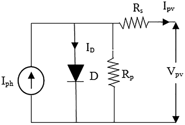
Figure 1: Electrical representation of a PV cell
2.2 Thermoelectric Generator Model
Recently, TEGs are considered the right device to convert waste thermal energy into useful electricity [31]. A TEG is made up of numerous TEEs that are electrically coupled according to the needed output rating. TEG is modeled as a voltage source, and its equivalent circuit is shown in Fig. 2. Eq. (5) expresses the voltage induced in the TEG [32].
where
where
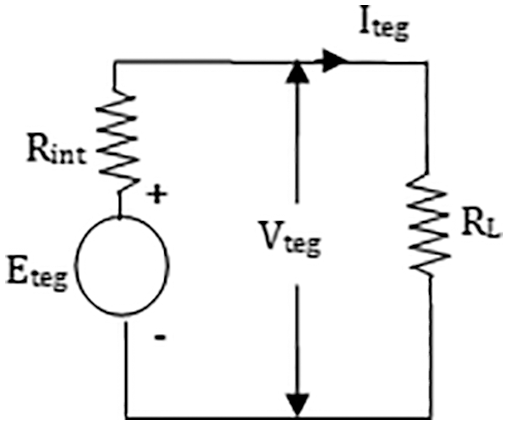
Figure 2: Electrical circuit of TEG
The electrical parameters of the TEG are expressed as in Eqs. (7)–(9)
where
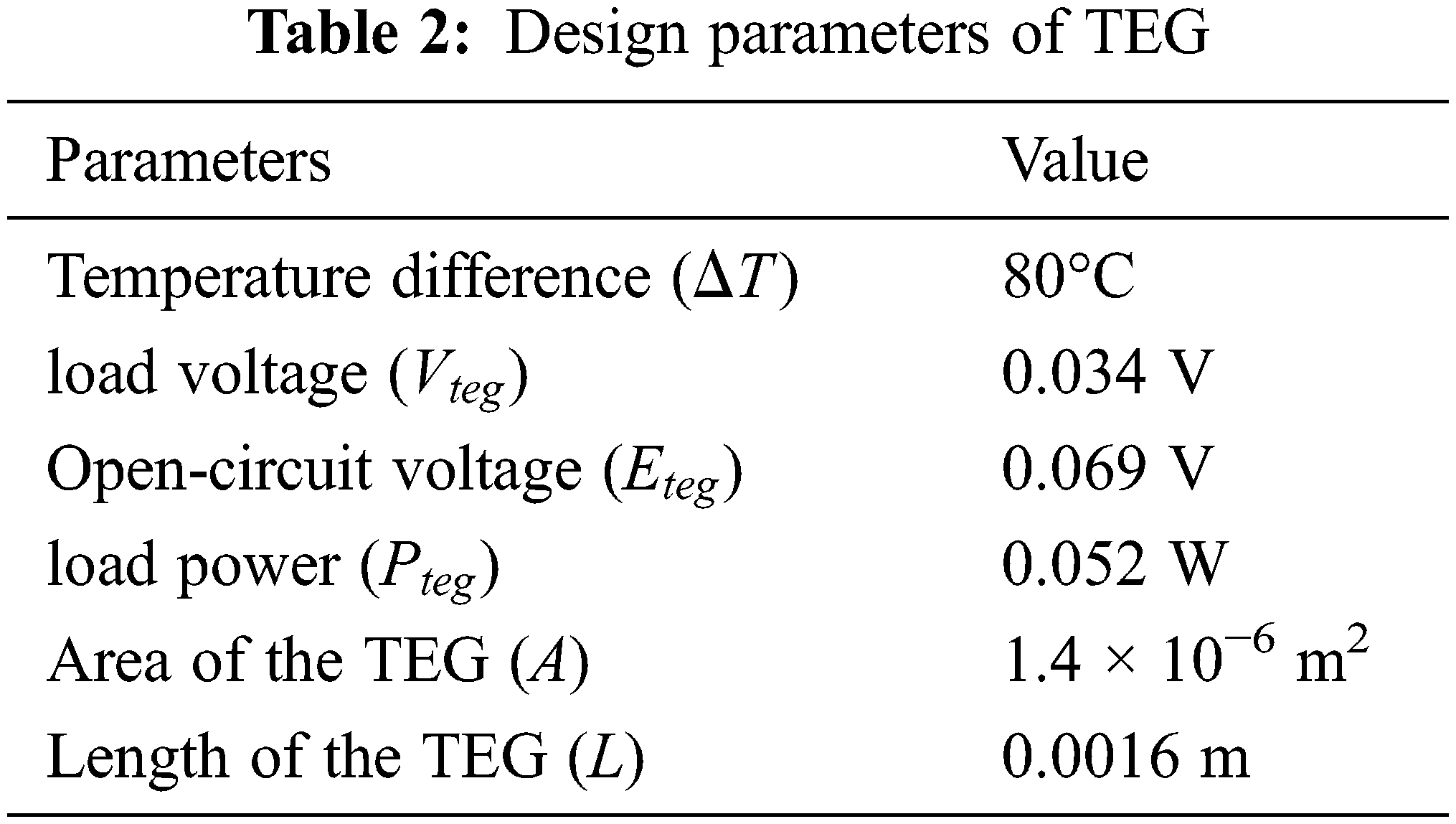
Fig. 3 depicts a schematic of the hybrid renewable energy system. The TEG and PV array are connected in series for the electric current flow and parallel for the heat flow. To achieve a sufficient temperature difference, the TEG hot side is connected to the PV panel, and heat sinks are installed on the cold side. The TEG will generate the voltage directly using the temperature difference between the hot and cold sides, as determined by Eq. (5). Furthermore, the use of TEG heat sinks reduces the temperature of the PV panel, which improves the energy generation efficiency of the PV cells significantly. The MPPT control is used only for the PV panel in the hybrid system, taking into account the contribution of maximum power output.
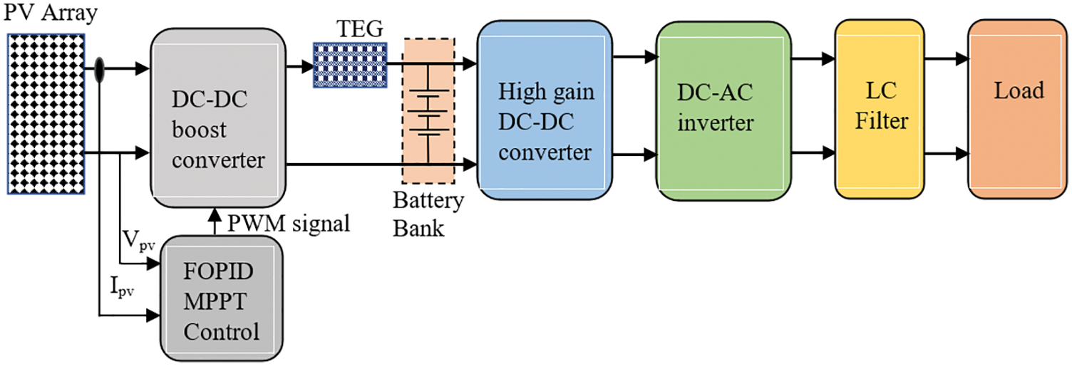
Figure 3: PV–TEG hybrid system configuration
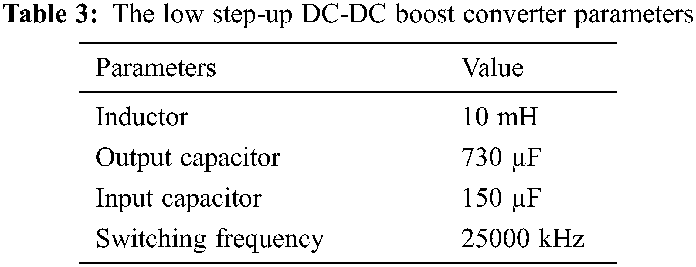
3.1 Low Step-Up DC-DC Boost Converter
The primary function of the DC-DC boost converter circuit is to adjust the voltage output in order to extract the maximum power from the PV array. The voltage is regulated by sending a fixed frequency and variable duty cycle pulse width modulation (PWM) signal to the converter circuit. The MPPT control algorithm (discussed further below) generates the control signal to fix the correct duty cycle of the PWM signal based on the PV array output. The low step-up DC-DC boost converter is designed using the procedure in [33], and the converter circuit is shown in Fig. 4. Tab. 3 specifies the value of the design parameter for the converter circuit. In general, the boost converter can be operated in two modes: (i) continuous conduction mode and (ii) discontinuous conduction mode; in this study, the efficient continuous conduction mode is used.
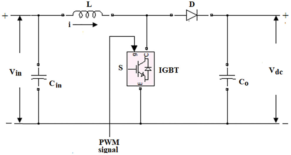
Figure 4: DC-DC boost converter
The inductor voltage of the boost converter can be determined [34] using Eq. (10), which is equal to the input voltage as in Eq. (11). The inductor voltage is also expressed in Eq. (12)
where
The average DC voltage output of the boost converter can be expressed in Eq. (14)
wherein duty cycle
where
The high-gain DC-DC converter is added to the system to maintain an adequate DC input voltage to the DC-AC inverter circuit. The high-gain DC-DC converter is selected because if the low output voltage of the PV array is amplified directly at a high level using an extreme duty cycle at the first stage converter circuit, it can cause more magnetic interference [34]. As a result, magnetic interference can be avoided by incorporating a high-gain DC-DC converter circuit, which will also improve energy conversion efficiency. The proposed system employs a coupled inductor type high-gain DC-DC converter, which boosts the input DC voltage of 25 V to 290 V at the output side. The control topology and circuit diagram are shown in Fig. 5. The voltage output of a high-gain DC-DC converter (
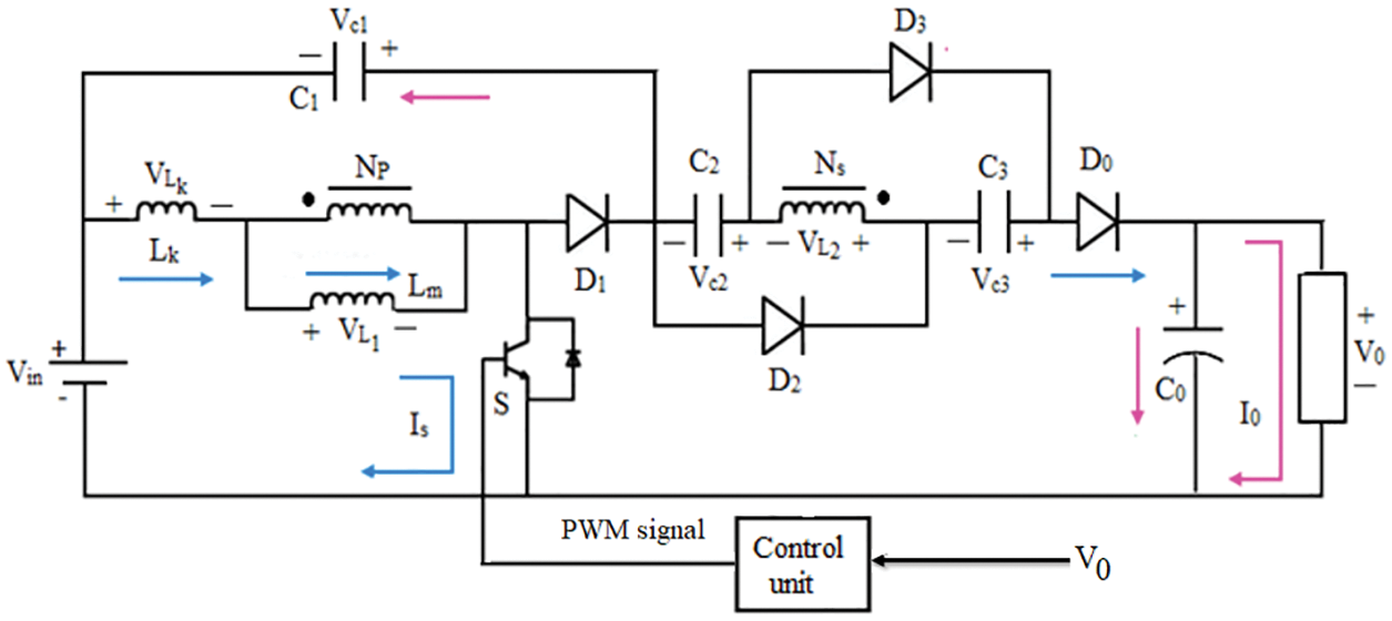
Figure 5: Circuit diagram of the high-gain DC-DC converter
3.3 DC-AC Voltage Source Inverter and Filter Circuit
The voltage source inverter (VSI) and filter circuit are used to convert the DC voltage into a sinusoidal alternating current (AC) voltage with the specified frequency and amplitude. The Insulated Gate Bipolar Transistor (IGBT) switches are widely employed in VSI circuits to improve the output voltage signal. The H-bridge type inverter is commonly used for single-phase supply [35]. Fig. 6 depicts a typical circuit arrangement for a two-arm, four-switch type inverter. When the switches
where
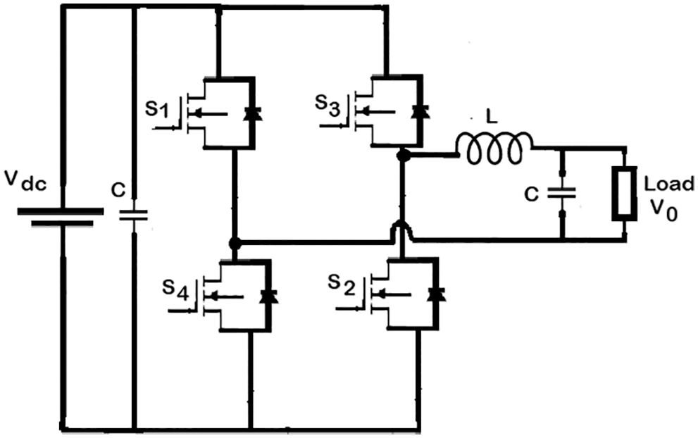
Figure 6: Circuit diagram of the VSI
Fractional order control is one of the recognized and widely preferred control techniques particularly, for nonlinear and complex systems. When compared to classical control, the FOC has two additional tuning parameters by which system robustness and stability can be improved. The FOPID controller is usually denoted as PIλDµ which is expressed by the following transfer function given in Eq. (18) [18],
where
where e(t) and u(t) are the error and control signals, respectively. Suppose in the above Eq. (19), the order of the integrator and differentiator are equal to unity (
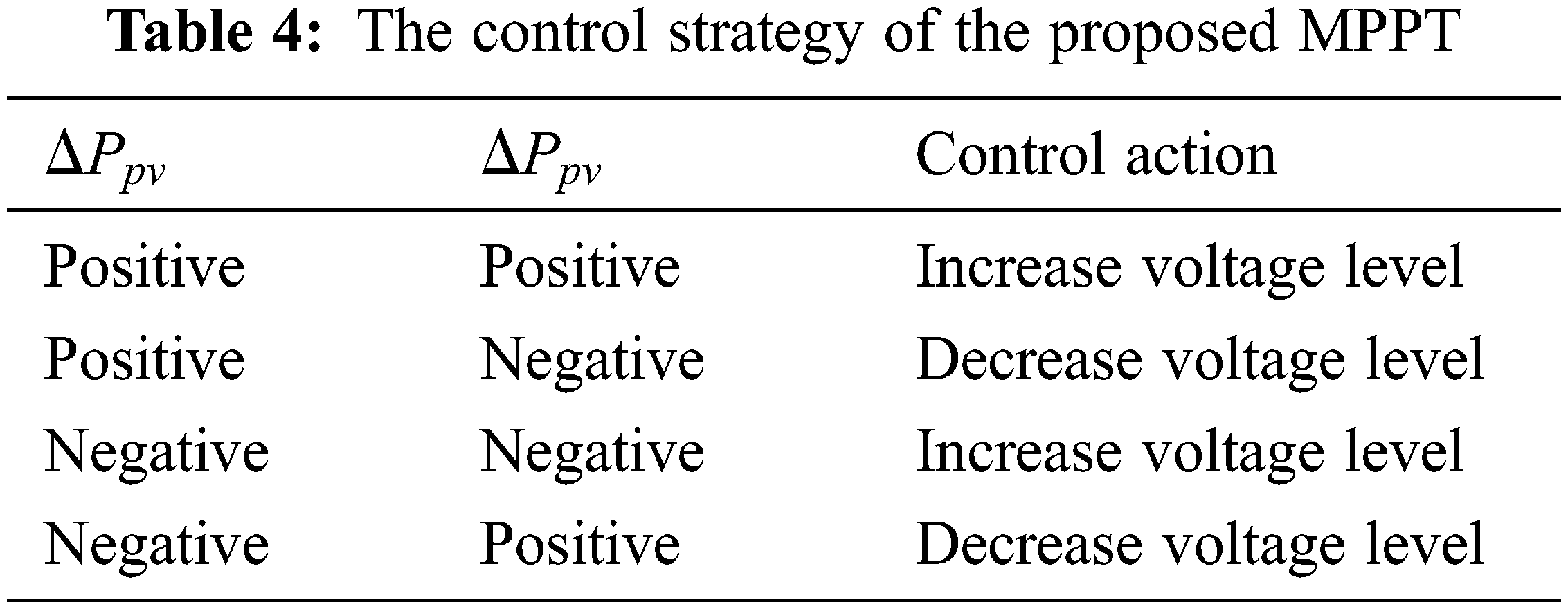
The MPPT control is used to extract the maximum power possible from the source, increasing the system’s energy generation efficiency. The MPPT control algorithm as shown in Fig. 7 shifts the system operating point closer to the peak of the power-voltage (P-V) curve. In the current system, the FOPID controller generates the appropriate control action to reach the MPP based on the error signal, which is calculated by dividing the change in power output by the change in voltage. Tab. 4 summarizes the control action for the MPPT. The FOPID controller’s input error
where
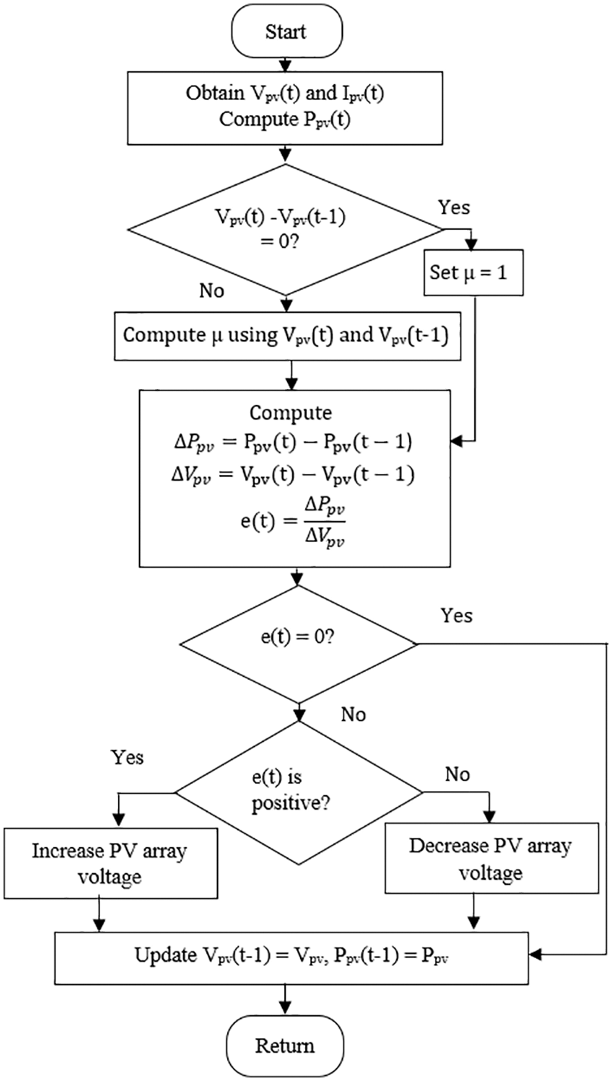
Figure 7: MPPT control logic algorithm
When the error is zero or very low, it indicates that the operating point of the system has already reached the MPP. Also, the control algorithm uses the value of change in the voltage (
An extensive simulation study was conducted using MATLAB software under various operating conditions to evaluate the effectiveness of the proposed MPPT control for hybrid renewable energy systems. The MATLAB/Simulink model of the PV-TEG hybrid energy system integrated with the FOPID controller is shown in Fig. 8. In the initial part of the study, the correctness of the designed PV model has been verified for a solar irradiation level of 1000 w/m2, the P-V curve of the designed model under different operating temperatures is shown in Fig. 9. The accuracy of the model is confirmed based on its peak power value for the chosen voltage. The energy conversion ability of the PV model was tested for the step-change in solar irradiation with a constant temperature of 25°C; the voltage and power output of the PV module is shown in Fig. 10. The study results show the dynamic performance of the PV array; the levels of the voltage and power output are correctly modified according to solar irradiation. Similarly, the TEG performance was investigated for a step-change in temperature difference, and the voltage output is depicted in Fig. 11. The voltage output of the TEG, as shown in Fig. 11, confirms its ability to convert energy.
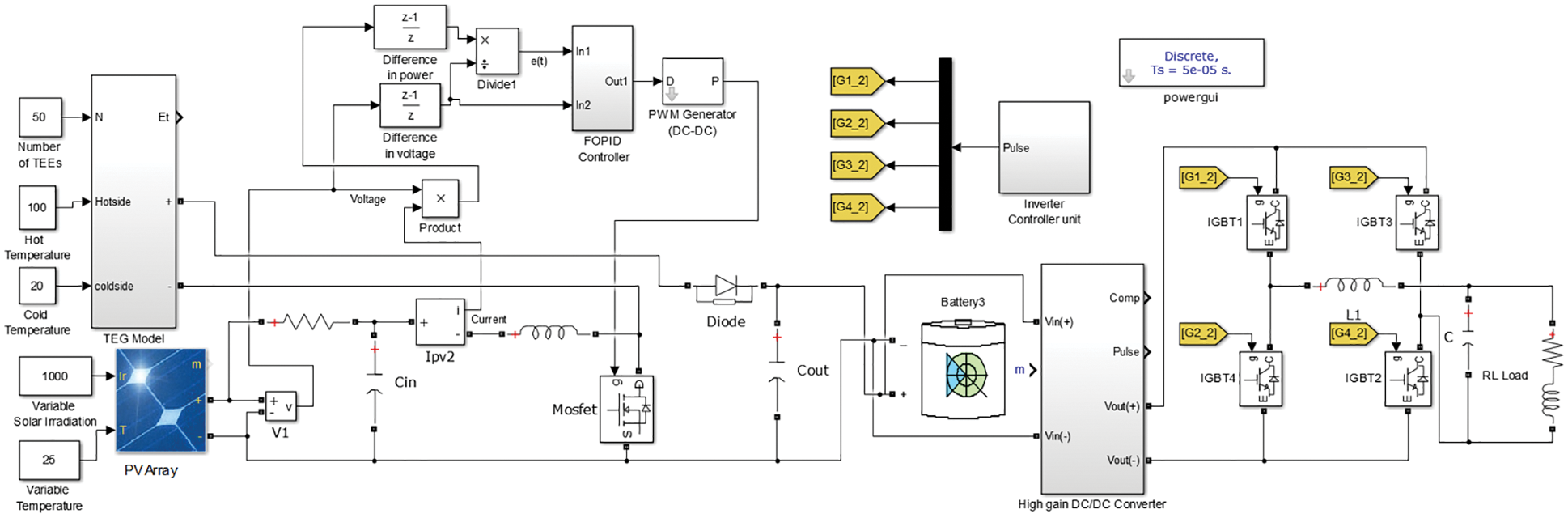
Figure 8: MATLAB/Simulink model of the proposed system
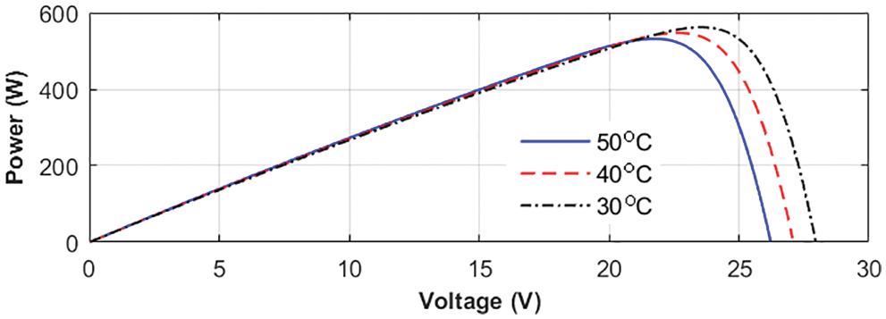
Figure 9: The P-V characteristics of the designed PV model for various operating temperatures
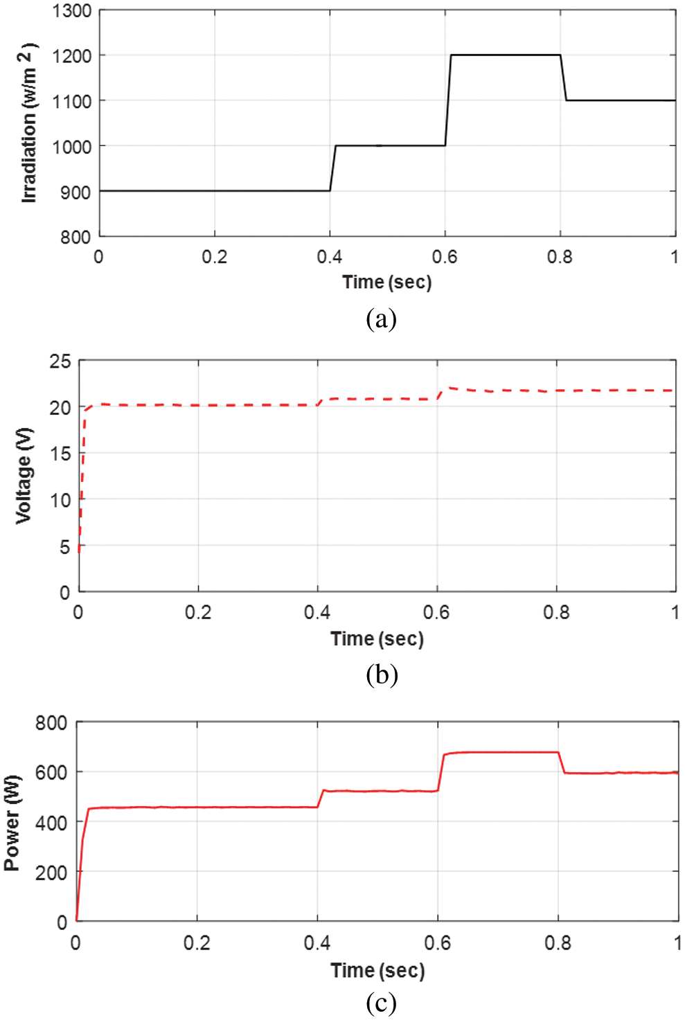
Figure 10: The PV array performance (a) step-change in solar irradiation input (b) voltage output (c) power output
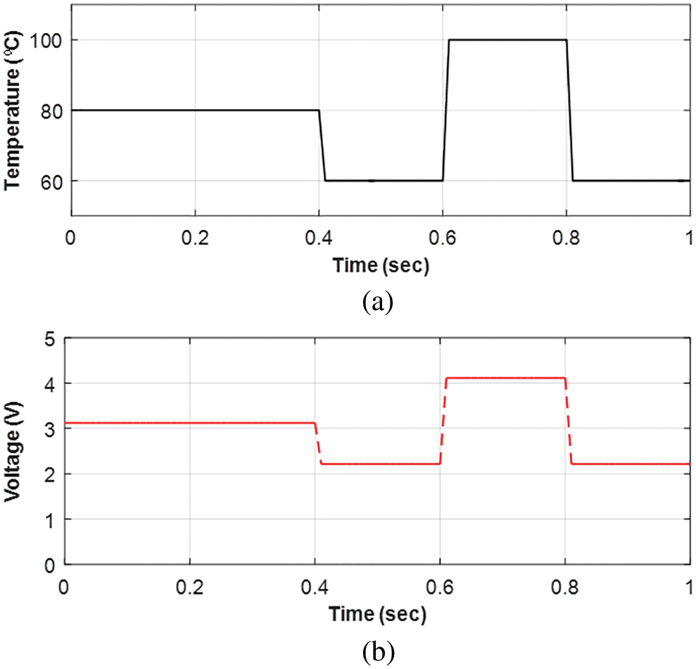
Figure 11: TEG’s performance (a) step-change in temperature difference input (b) voltage output
The high-gain DC-DC converter’s voltage amplification capability is also tested to ensure that it will function in the current system. The test was carried out by keeping the irradiation and temperature values for the PV array at 1000 w/m2 and 25°C, respectively, and an 80°C temperature difference between the cold and hot junction in TEG. As shown in Fig. 12, the converter circuit amplifies the 28 V input voltage to 295 V. Furthermore, the high-gain DC-DC converter quickly amplifies the input voltage to the required level and then maintains the voltage level with little variation. The constant DC voltage output of the converter is required to maintain a constant AC voltage across the load when using the DC-AC inverter circuit. In addition, the performance of the DC-AC inverter is investigated by connecting an RL load to the output side. The voltage and current flow at the load side are observed as the PV array's solar irradiation and temperature differences across the input terminal of the TEG vary. The observation is shown in Fig. 13; it is seen that the two-arm four-switch inverter DC-AC circuit function correctly modifies the input DC voltage into a pure AC supply without any distortion. Further, the inverter circuit maintains a constant frequency AC supply across the load. Therefore, it is confirmed that the various parts of the proposed FOPID controller-based hybrid energy system are working effectively to produce electricity and to supply the required power to the load.
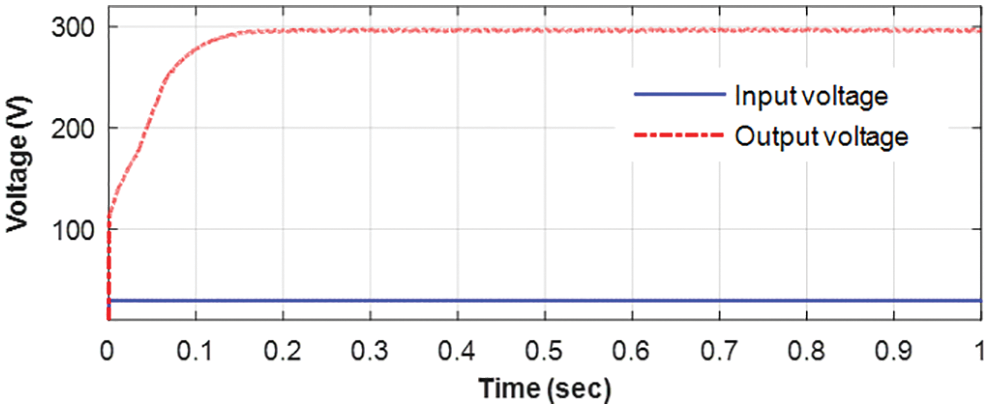
Figure 12: High-gain DC-DC converter performance
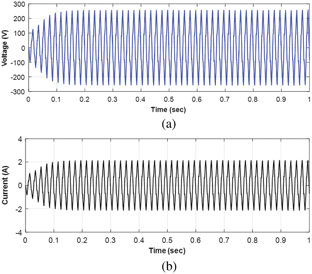
Figure 13: AC-DC inverter output (a) voltage level (b) current flow
The performance of the proposed FOPID controller combined with the PV-TEG hybrid system was investigated under continuously varying solar irradiation, with the PV input irradiation level being adjusted at different time intervals, as shown in Fig. 14a. Figs. 14b and 14c show the voltage and power output during this study. As a result, the hybrid source outputs perfectly follow the variation in solar irradiation by adjusting the output level quickly and without delay. The computation capability of the FOPID-based MPPT control algorithm is reflected in this result. In addition, the output of the high-gain DC-DC converter and the voltage across load during this study show improved results, as shown in Figs. 15 and 16. The results of Figs. 15 and 16 show that the proposed FOPID controller will efficiently perform the MPPT to extract the maximum power from the hybrid PV-TEG renewable energy source. Furthermore, even if the input parameters at the source change, the single load receives a pure AC voltage continuously.
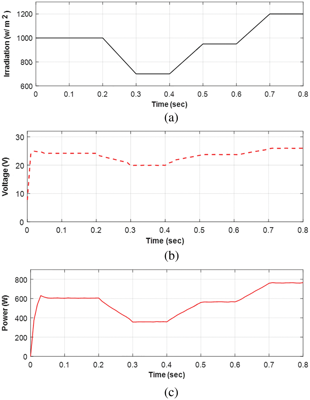
Figure 14: Hybrid system performance (a) input solar irradiation (b) system output voltage (c) output power

Figure 15: High-gain DC-DC converter output for the continuously changing input solar irradiation
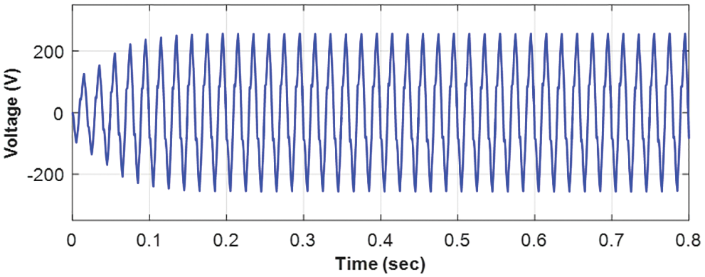
Figure 16: DC-AC inverter output for the continuously changing input solar irradiation
To demonstrate the benefits, the proposed FOPID controller-based MPPT technique for the hybrid PV-TEG system is compared to the P&O type MPPT method. The comparison results are shown in Figs. 17a and 17b. Under the P&O MPPT method, the PV-TEG output takes a long time to reach the final steady-state level of voltage and power. The same voltage and power outputs, however, provide the final value quickly when using the FOPID controller-based MPPT method.

Figure 17: MPPT control comparison (a) voltage output (b) power output
To improve tracking speed and obtain steady-state output, a new MPPT control algorithm has been proposed. The proposed control scheme has been verified using a modified FOPID control structure with a dynamically varying derivative order number. To achieve good tracking performance, the value of µ was set between 0.1 and 0.9 during tracking and as 1 at MPP. To evaluate the proposed MPPT control scheme, the PV-TEG combined hybrid system model was created. The results of the simulation study confirmed that the proposed control method performs better during transient and steady-state conditions to extract the maximum power. Furthermore, the performance comparison of the proposed and P&O type MPPT control demonstrated that the proposed method has a better tracking ability to quickly achieve the MPP. The faster tracking and steady-state output at MPP can improve the system’s energy generation efficiency by reducing power losses caused by the longer tracking time
Funding Statement: The authors extend their appreciation to the Deputyship for Research & Innovation, Ministry of Education in Saudi Arabia for funding this research work through the Project Number (IF-PSAU-2021/ 01/18128).
Conflicts of Interest: The authors declare that they have no conflicts of interest to report regarding the present study.
References
1. D. Timmons, A. Dhunny, K. Elahee, B. Havumaki, M. Howells et al., “Cost minimization for fully renewable electricity systems: A Mauritius case study,” Energy Policy, vol. 133, no. 2, pp. 110895, 2019. [Google Scholar]
2. S. Wang, B. Tarroja, L. Schell and S. Samuelsen, “Determining cost-optimal approaches for managing excess renewable electricity in decarbonized electricity systems,” Renewable Energy, vol. 178, pp. 1187–1197, 2021. [Google Scholar]
3. E. Semshchikov, M. Negnevitsky, J. Hamilton and X. Wang, “Cost-efficient strategy for high renewable energy penetration in isolated power systems,” IEEE Transactions on Power Systems, vol. 35, no. 5, pp. 3719–3728, 2020. [Google Scholar]
4. S. Ahmet, I. Kehinde and S. Abdullah, “A review on the performance of photovoltaic/thermoelectric hybrid generators,” International Journal of Energy Research, vol. 44, no. 5, pp. 3365–3394, 2020. [Google Scholar]
5. V. Verma, A. Kane and B. Singh, “Complementary performance enhancement of PV energy system through thermoelectric generation,” Renewable and Sustainable Energy Reviews, vol. 58, no. 5, pp. 1017–1026, 2016. [Google Scholar]
6. I. Hong, B. Kang and S. Park, “Design and implementation of intelligent energy distribution management with photovoltaic system,” IEEE Transactions on Consumer Electronics, vol. 58, no. 2, pp. 340–346, 2012. [Google Scholar]
7. R. B. Ammar, M. B. Ammar and A. Oualha, “Photovoltaic power forecast using empirical models and artificial intelligence approaches for water pumping systems,” Renewable Energy, vol. 153, no. 5, pp. 1016–1028, 2020. [Google Scholar]
8. Z. Naghibi, S. Ekhtiari, R. Carriveau and D. S.-K. Ting, “Hybrid solar thermal/photovoltaic-battery energy storage system in a commercial greenhouse: Performance and economic analysis,” Energy Storage, vol. 3, no. 1, pp. 42, 2021. [Google Scholar]
9. N. M. Mukundan, V. Kallaveetil, S. S. Kumar and J. Pychadathil, “An improved H-Bridge multilevel inverter-based multiobjective photovoltaic power conversion system,” IEEE Transactions on Industry Applications, vol. 57, no. 6, pp. 6339–6349, 2021. [Google Scholar]
10. Z. Shen, H. Ni, C. Ding, G. Sui, H. Jia et al., “Improving the energy-conversion efficiency of a PV-TE system with an intelligent power-track switching technique and efficient thermal-management scheme,” IEEE Transactions on Components, Packaging and Manufacturing Technology, vol. 11, no. 6, pp. 963–973, 2021. [Google Scholar]
11. Z. Zhou, Y. Jiang, N. E-Daukes, M. Keevers and M. A. Green, “Optical and thermal emission benefits of differently textured glass for photovoltaic modules,” IEEE Journal of Photovoltaics, vol. 11, no. 1, pp. 131–137, 2021. [Google Scholar]
12. H. Fathabadi, “Improving the power efficiency of a PV power generation system using a proposed electrochemical heat engine embedded in the system,” IEEE Transactions on Power Electronics, vol. 34, no. 9, pp. 8626–8633, 2019. [Google Scholar]
13. N. Kanagaraj, H. Rezk and M. R. Gomaa, “A variable fractional order fuzzy logic control based MPPT technique for improving energy conversion efficiency of thermoelectric power generator,” Energies, vol. 13, no. 17, pp. 4531, 2020. [Google Scholar]
14. C. Xu, K. Itako, T. Kudoh, K. Koh and Q. Ge, “Proposal for an active PV array to improve system efficiency during partial shading,” IEEE Access, vol. 9, pp. 143423–143433, 2021. [Google Scholar]
15. A. Driesse, M. Theristis and J. S. Stein, “A new photovoltaic module efficiency model for energy prediction and rating,” IEEE Journal of Photovoltaics, vol. 11, no. 2, pp. 527–534, 2021. [Google Scholar]
16. K. H. Ang, G. Chong and Y. Li, “PID control system analysis, design and technology,” IEEE Transactions on Control Systems Technology, vol. 13, no. 4, pp. 559–576, 2005. [Google Scholar]
17. S. Hamamci, “An algorithm for stabilization of fractional-order time delay systems using fractional-order PID controllers,” IEEE Transactions on Automatic Control, vol. 52, no. 10, pp. 1964–1969, 2007. [Google Scholar]
18. N. Kanagaraj and V. N. Jha, “Design and performance evaluation of an improved fractional order PID controller for a class of second order plant,” International Journal for Computation and Mathematics in Electrical and Electronic Engineering, vol. 40, no. 3, pp. 579–592, 2021. [Google Scholar]
19. M. Aburakhis and R. Ordóñez, “Interaction of fractional order adaptive law and fractional order PID controller for the ball and beam control system,” in Proc. IEEE National Aerospace and Electronics NAECON Conf., Ohio, USA, pp. 451–456, 2018. [Google Scholar]
20. M. Ghorbani, M. Tavakoli-Kakhki, A. Tepljakov, E. Petlenkov, A. Farnam et al., “Robust stability analysis of interval fractional-order plants with interval time delay and general form of fractional-order controllers,” IEEE Control Systems Letters, vol. 6, pp. 1268–1273, 2022. [Google Scholar]
21. F. Padula and A. Visioli, “Tuning rules for optimal PID and fractional-order PID controllers,” Journal of Process Control, vol. 21, no. 1, pp. 69–81, 2011. [Google Scholar]
22. P. Wang, B. L. Wang and J. E. Li, “Temperature and performance modeling of thermoelectric generators,” International Journal of Heat and Mass Transfer, vol. 143, pp. 1145–1153, 2019. [Google Scholar]
23. K. Karthick, K. Suresh, S. Joy and G. C. Dhanuskodi, “Experimental investigation of solar reversible power generation in thermoelectric generator (TEG) using thermal energy storage,” Energy for Sustainable Development, vol. 48, no. 2, pp. 107–114, 2018. [Google Scholar]
24. S. Qing, A. Rezania, L. Rosendahl and X. Gou, “An analytical model for performance optimization of thermoelectric generator with temperature dependent materials,” IEEE Access, vol. 6, pp. 60852–60861, 2018. [Google Scholar]
25. X. Gou, H. Xiao and S. Yang, “Modeling, experimental study and optimization on low-temperature waste heat thermoelectric generator system,” Applied Thermal Engineering, vol. 87, no. 10, pp. 3131–3136, 2010. [Google Scholar]
26. Y. Hsiao, W. Chang and S. Chen, “A mathematic model of thermoelectric module with applications on waste heat recovery from automobile engine,” Energy, vol. 35, no. 3, pp. 1447–1454, 2010. [Google Scholar]
27. N. Kanagaraj, “Photovoltaic and thermoelectric generator combined hybrid energy system with an enhanced maximum power point tracking technique for higher energy conversion efficiency,” Sustainability, vol. 13, no. 6, pp. 3144, 2021. [Google Scholar]
28. A. Rezania, D. Sera and L. Rosendahl, “Coupled thermal model of photovoltaic-thermoelectric hybrid panel for sample cities in Europe,” Renew Energy, vol. 99, pp. 127–135, 2016. [Google Scholar]
29. J. Lin, T. Liao and B. Lin, “Performance analysis and load matching of a photovoltaic-thermoelectric hybrid system, energy convers,” Energy Conversion and Management, vol. 105, no. 2, pp. 891–899, 2015. [Google Scholar]
30. M. Makhlouf, F. Messai and H. Benalla, “Modeling and simulation of grid-connected hybrid photovoltaic/battery distributed generation system,” Canadian Journal on Electrical and Electronics Engineering, vol. 3, no. 1, pp. 1–10, 2012. [Google Scholar]
31. S. Qing, A. Rezania, L. Rosendahl and X. Gou, “An analytical model for performance optimization of thermoelectric generator with temperature dependent materials,” IEEE Access, vol. 6, pp. 60852–60861, 2018. [Google Scholar]
32. N. Kanagaraj, “An enhanced maximum power point tracking method for thermoelectric generator using adaptive neuro‐fuzzy inference system,” Journal of Electrical Engineering & Technology, vol. 16, pp. 1207–1218, 2021. [Google Scholar]
33. M. Rashid, “Power Electronics Handbook.” Burlington, MA, Saint Louis: Elsevier Science, 2017. [Online]. Available at: https://www.worldcat.org/title/power-electronics-handbook/oclc/1004201783. [Google Scholar]
34. M. Ramasamy and S. Thangavel, “Experimental verification of PV based dynamic voltage restorer (PV-DVR) with significant energy conservation,” International Journal of Electrical Power and Energy Systems, vol. 49, no. 1, pp. 296–307, 2013. [Google Scholar]
35. N. Kanagaraj, “Hybrid renewable energy source combined dynamic voltage restorer for power quality improvement,” Computer Systems Science and Engineering, vol. 40, no. 2, pp. 517–538, 2022. [Google Scholar]
36. D. Guha, P. K. Roy, S. Banerjee, S. Padmanaban, F. Blaabjerg et al., “Small-signal stability analysis of hybrid power system with quasi-oppositional sine cosine algorithm optimized fractional order PID controller,” IEEE Access, vol. 8, pp. 155971–155986, 2020. [Google Scholar]
Cite This Article
 Copyright © 2023 The Author(s). Published by Tech Science Press.
This work is licensed under a Creative Commons Attribution 4.0 International License , which permits unrestricted use, distribution, and reproduction in any medium, provided the original work is properly cited.
 Downloads
 Citation Tools