
 Submit a Paper
 Propose a Special lssue
 Open Access
ARTICLE

Development of Energy Management System for Micro Grid Operation
1 School of Electrical and Electronics Engineering, Sathyabama Institute of Science and Technology, Chennai, Tamil Nadu, India
2 Department of Electronics and Communication Engineering, Muthayammal Engineering College (Autonomous), Rasipuram, Tamil Nadu, India
3 Department of Electrical and Electronics Engineering, Ahalia School of Engineering and Technology, Kozhipara, Palakkad, Kerala, India
4 Department of Electrical and Electronics Engineering, NSS College of Engineering, Palakkad, Kerala, India
5 Department of Electrical and Electronics Engineering, Panimalar Engineering College, Chennai, Tamil Nadu, India
6 Department of Electrical and Electronics Engineering, GRT Institute of Engineering and Technology, Tiruttani, Thiruvallur, Tamil Nadu, India
* Corresponding Author: S. Jayaprakash. Email:
Computer Systems Science and Engineering 2023, 45(3), 2537-2551. https://doi.org/10.32604/csse.2023.032038
Received 04 May 2022; Accepted 16 June 2022; Issue published 21 December 2022
 View Full Text
 Download PDF
Abstract
The introduction of several small and large-scale industries, malls, shopping complexes, and domestic applications has significantly increased energy consumption. The aim of the work is to simulate a technically viable and economically optimum hybrid power system for residential buildings. The proposed micro-grid model includes four power generators: solar power, wind power, Electricity Board (EB) source, and a Diesel Generator (DG) set, with solar and wind power performing as major sources and the EB supply and DG set serving as backup sources. The core issue in direct current to alternate current conversion is harmonics distortion, a five-stage multilevel inverter is employed with the assistance of an intelligent control system is simulated and the optimum system configuration is estimated to reduce harmonics and improve the power quality. The monthly demand for residential buildings is 13–15 Megawatts. So, almost 433 Kilo-Watts (KW) of electricity is required every day, and if it is used for 8 h per day, 50–60 KW of electricity is needed per hour. The overall micro-grid model’s operation and performance are established using MATLAB/SIMULINK software, and simulation results are provided. The simulation results show that the developed system is both cost-effective and environment friendly resulting in yearly cost reductions.Keywords
Nearly 75% of electricity is produced from the thermal power plant on the generation side. There are 15 coal reserves in India, producing 319 billion metric tons of coal every year. India's coal consumption was reported at 452.221 tonne of oil equivalent in December 2018 [1]. In the future, the demand will increase more. As the demand increases, India’s last thermal power plant will be closed by 2050.
On the other hand, there are some significant disadvantages to coal-fired power plants: greenhouse gas emissions, mining destructions, generation of million tons of waste, and harmful substances. So India needs to work on generating electricity from renewable resources [2,3]. These research works are similarly implemented, which slightly differs from methodologies. Formally mentioned, one is a case study of the economic modeling of a hybrid renewable energy system. The second mentioned work is hybrid renewable energy sources using new and optimization techniques. This technology is executed flexibly utilizing a novel computer program that is not accessible in any market-available software, such as homer or retscreen software. Then developed computer software progressively modifies the wind/ PhotoVoltaic (PV) penetration ratio and calculates the needed size of all components and the optimal battery capacity to achieve the preset lowest tolerable probability.
Increasing renewable resource usage is the ideal solution to meet the increasing demand without any harmful emissions. Microgrids are used for integrating renewable resources such as solar and wind along with the power from the grid [4]. Advantages of microgrids include energy efficiency, minimization of overall energy consumption, improved environmental impact, improvement of energy system reliability, network benefits, and cost-efficient electricity infrastructure replacement [5,6].
With the advancement in power electronic technology, Direct Current (DC) microgrids are more preferred than Alternate Current (AC) microgrids, including high efficiency, reliability, stability, and cost [7]. Because less power electronic converters are required, overall efficiency improves. Furthermore, because AC/DC converters do not require a transformer, the size of a DC microgrid is significantly reduced. DC microgrids increase the introduction of distributed PV units. It reduces energy dissipation and facility costs. It also supplies power to the load even during the blackout of commercial grids. DC microgrid reduces the power conversions [8,9]. A microgrid is a combination of interconnected loads and distributed energy resources that operates as a single controllable entity with respect to the grid [10]. A microgrid has the ability to connect and disconnect from the grid, allowing it to operate in both grid-connected and island mode. In this paper, the optimized Energy Management System (EMS) is designed using intelligent control system. Optimization is performed to increase the usage of renewable resources and reduce the cost of electricity.
Our proposed DC microgrid system integrates solar energy, wind energy, Electricity Board (EB) source, DG, and an optimized EMS using an intelligent control system. The overall scheme of the proposed hybrid renewable power management system is given in Fig. 1.
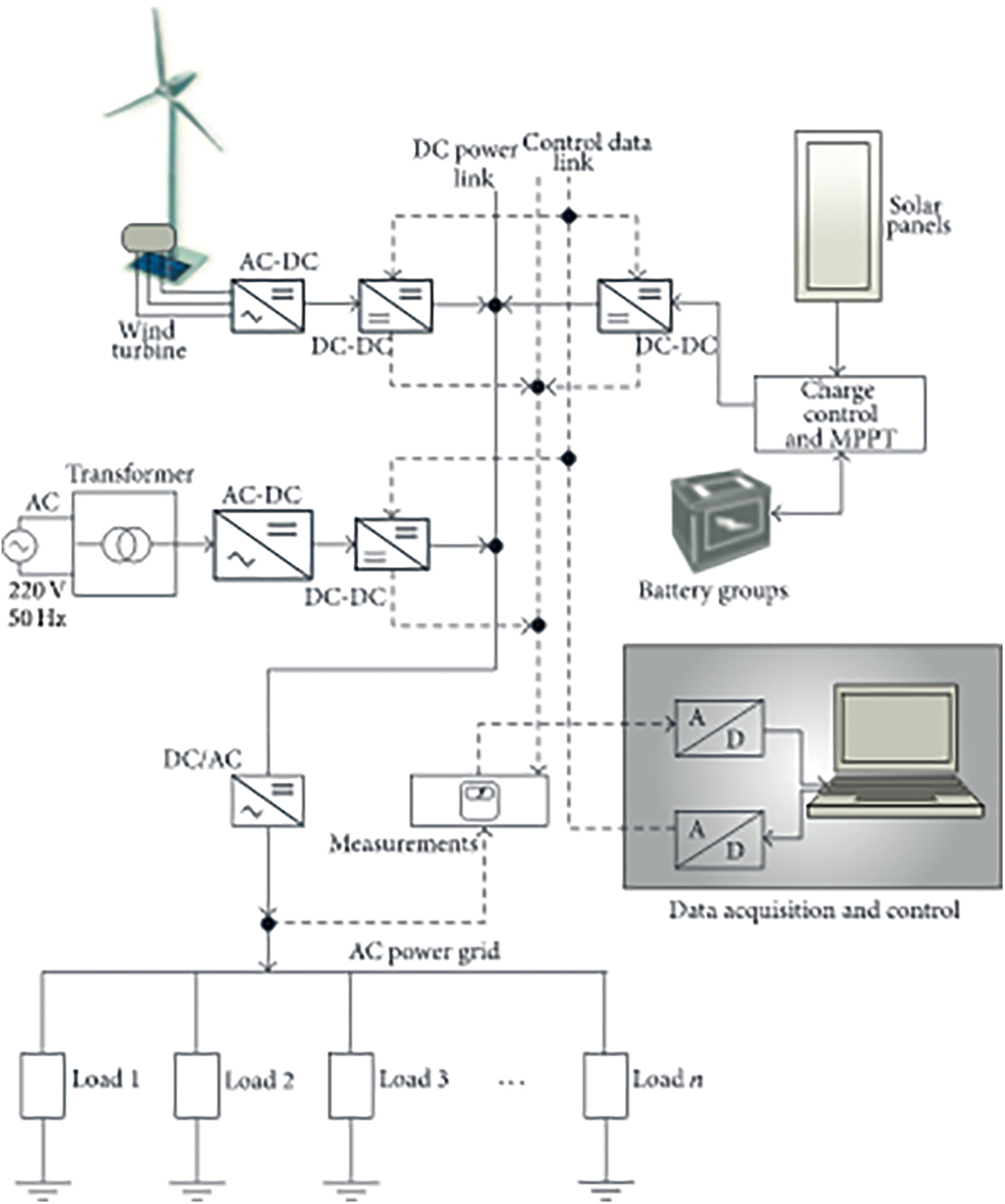
Figure 1: Block diagram of the proposed system
The system consists of PV and wind power generating units, EB source, and Diesel Generator (DG) as hybrid electrical sources. These four generating units are connected to a DC power pool over the required converters. A backup battery group is also connected to the PV system to store the extra generated solar power when all generated power from the PV is not delivered to the load [11]. AC load types are considered in the system, and they are connected to the AC power bus, which is fed from the common DC power pool [12]. Data collected from the source side and load side is transferred to a computer to be evaluated for the decision-making process of the power management system. Wind turbines employ blades to gather the kinetic energy of the wind. The wind blows over the blades, providing lift and causing the blades to spin. The blades are linked to a driving shaft, which spins an electric generator, which generates power [13]. Solar PV cells are used to absorb solar energy from the sun. These liberated electrons are transported to a positive terminal, which sends them into an electric circuit, where they cause electricity to flow as light and heat through wires. Since the release of updated objectives for the national solar mission in 2015, solar tariffs have been continuously decreasing [14].
The power management algorithm is developed to operate both PhotoVoltaic Energy Systems (PVES) and Wind Energy Systems (WES) at the maximum power they can generate under various environmental conditions while maintaining the power supply demand of the load side at the required amount. A DG can also be used with renewable energy sources such as wind turbines and solar panels to create an excellent choice for independent power generation in an island situation [15]. Home, EMSs assist in controlling power demand to optimize energy usage and distribute renewable energy generation while maintaining customers’ comfort [16].
A stochastic transmission switching integrated interval robust chance-constrained technique is used to evaluate the functioning of a wind park-energy storage system in a day-ahead electricity market while considering technical constraints [17]. Therefore, power management includes maximum power point tracking of PVES and WES, energy storage, utility connection, and load switching. Besides, the power quality issues such as harmonic elimination, voltage sags, voltage increments, frequency deviations, and voltage magnitude are included in the management system. There are too many inputs and parameters in the management decision algorithms. An intelligent control system is used to achieve optimal operation and maintenance costs. The EMS is designed for the microgrid to monitor, control and optimize the performance of the generating stations.
3 Mathematical Model of Microgrid
1. The Solar Power Generation Unit
The solar power generation cost depends on investment, maintenance, and operational cost. To maximize the utilization of renewable resources, the generated power is directly transferred to the load. The cost function is defined as,
where
2. Wind Power Generation Unit
Wind power generation depends on investment, maintenance, and operational costs. To maximize the utilization of renewable sources, the generated power is directly transferred to the load. The cost function is defined as,
where
3. Diesel Generator
The cost function of the DG is expressed in quadratic equations. They are defined as,
where
4. Power Grid
As the power from the microgrid is interpreted, it operates along with the power from the main grid. The cost equation for the power drawn from the utility grid is expressed as
where
The EMS offers a two-way transfer of power from the utility grid to load and from microgrid to utility grid. The cost function of the power given to the utility grid is expressed as,
5. Load Dispatch Model
The EMS operation is broadly classified into three stages: data acquisition, finding the optimal mode of operation, and dispatching the power to the load. The mode of operation is decided based on the power demand from the load side. It can be expressed as,
Mode 1: EMS is designed to utilize the maximum electricity from renewable resources. So, initially, the demand is checked with renewable resources. If it satisfies, then power from solar and wind is dispatched to the load.
Mode 2: The optimization model is performed using an intelligent control system. Then, based on the optimization result, power from various resources is transferred to the load
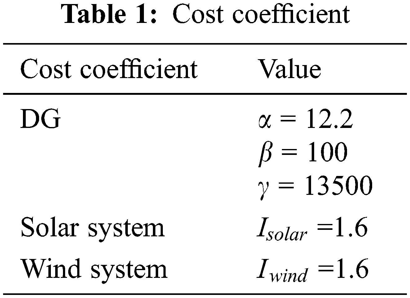
The remaining power for the load is taken from the power grid to reduce the cost. The DG is turned on when power is lost from the grid. The cost of power from the DG is greater than the power grid. Tab. 1 shows the cost coefficient.
The objective of this study is to allocate the load with given resources at a low cost. The objective function takes chromosomes as input, then produces the result and quantifies how good the chromosome is. The function is expressed as,
where
The constraints for the optimization problem are described. It includes each source's maximum and minimum capacity (solar, wind, diesel, and power grid).
where
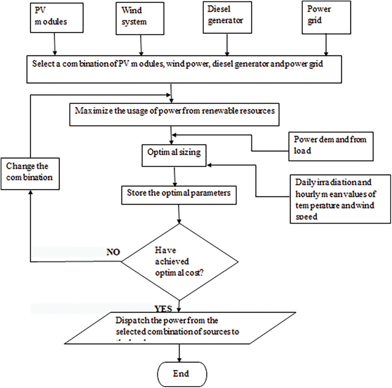
Figure 2: Flow chart for the optimization process
A high sensitive and fast response controller should depend on the performance of the comparator. The designed load comparator acts as an intelligent section of a comparator integrated circuit. The comparator recognizes the system input and output (residential demand and an output of the energy sources) behavior properly and fastly through simulation. Once the process starts, the comparator simultaneously compares the residential demand with the solar power output and wind power output. The switching can deliver a load to the residential buildings with reference to the comparator output. If the solar power output is greater than the wind power output, solar power is primarily delivered to the residential buildings.
Once the solar energy is not mature enough to meet all the energy requirements, the process switches over to the wind power system to feed the essential load to the correspondence. Suppose both the wind and solar energy sources fail to satisfy the required demand. In that case, the switching controller turns ON, and the power supply process switches over to the EB source to manage the remaining loads based on the designed logical controller. The logical controller implements the required logical operation derived from its inputs. The block diagram of the proposed logical controller and its truth table is represented in Fig. 3.
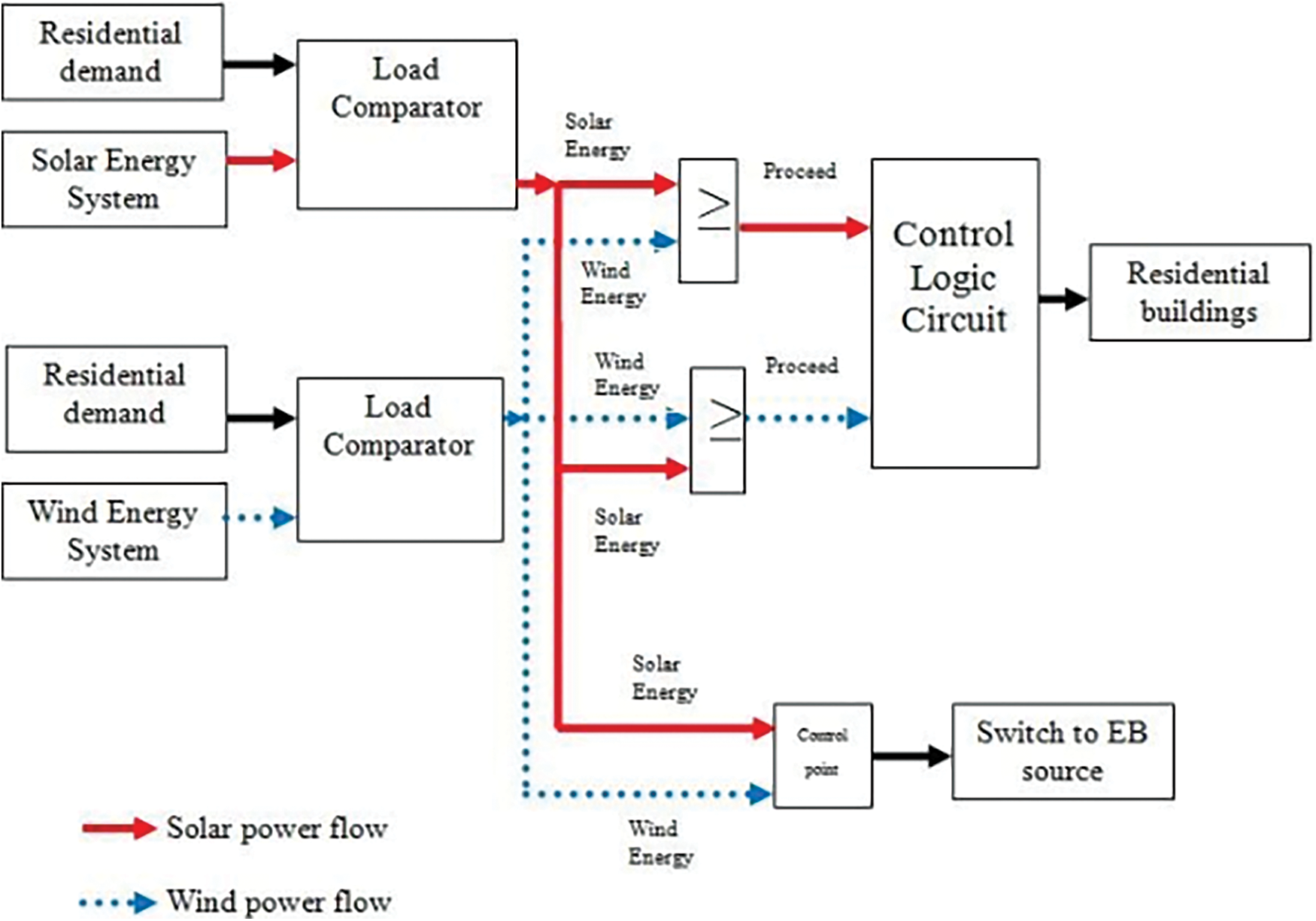
Figure 3: Block diagram of the proposed controller
The designed control logic circuit consists of two inputs (solar power and wind power) and one output (control output) which is based on the OR operation (TRUE (1) if at least one input is TRUE (1)). CP is the Control Point that reads the solar and wind power output and decides when to switch to the EB source. The working of the developed logic controller is described as follows:
Case (i): If the solar output power is greater than or equal to the wind output power, then the solar power’s state is 1. The state of wind power is 0. Therefore the state of the control output is 1, and so the structure allows the solar power system to start delivering power to the residential.
Case (ii): If the wind output power is greater than or equal to the solar output power, then the wind power state is 1. The state of solar power is 0. Therefore the state of the control output is 1, and so the structure allows the wind power system to start delivering power to the residential. When the power generated by the solar modules is less than the reference value (residential load), the inverter connected to the solar modules will be turned off automatically.
Case (iii): If the solar output power is equal to the wind output power, then the solar power’s state is 1. The state of wind power is 1. Therefore the state of the control output is 1. So the structure allows the solar or wind power system to start delivering power to the residential based on the conditions given (A breaker circuit may be employed in the physical line for power switching).
Case (iv): If both the solar output power and wind output power are equal to zero, then the solar power’s state is 0. The state of wind power is 0. Therefore the state of the control output is 0, and so the structure will not allow the solar or wind power system to start delivering power to the 52 residential instead, the system has switched over to the EB source to satisfy the remaining loads to the residential
5 Simulation of DC Microgrid with EMS System
A DC microgrid with an EMS system is designed and validated using MATLAB/SIMULINK. It consists of three sources (namely solar, wind, EB source, and DG), EMS block, DC microgrid, and multilevel inverter. The EMS monitors the output of all the sources. Residential monthly demand is 13–15 megawatts, estimated from an implemented microgrid. EMS supplies the power to the load by controlling all three sources based on the load requirement. The solar system is designed and controlled using the Maximum Power Point Tracking (MPPT) algorithm. The wind system is controlled using a normal Phase Width Modulation (PWM) controller. PWM is a modulation method that produces variable-width pulses to represent the amplitude of an analog input signal. For a high-amplitude signal, the output switching transistor is on more of the time, and for a low-amplitude signal, it is off more.
Similarly, a DG is controlled. The optimized EMS is designed using intelligent control system. Optimization is introduced to maximize the usage of renewable resources and reduce costs. The solar system is designed with an MPPT algorithm to maximize the output of solar panels by tracking the maximum power point. The output is DC, so the output power is directly given to EMS. The wind output is AC, but it fluctuates in power and frequency. So it is converted into DC and fed to the grid. The output power is also given to the EMS. The output of the DG is also converted into DC and fed into a microgrid.
EMS performs the economic load dispatch model by monitoring all the outputs of power sources and the power grid. DC power from the microgrid is converted into AC using a five-stage multilevel inverter. A multilevel inverter is a power electronic device that can provide the appropriate alternating voltage level at the output while taking many lower-level DC voltages as input. A five-level inverter is often used to create AC voltage from DC voltage. By using a multilevel inverter, total harmonic distortions are reduced.
Generally, polycrystalline solar panels are utilized because it has cheap and has a more straightforward production process. Polycrystalline solar panels have a low heat tolerance. There is less silicon waste when these panels are manufactured. The real-time system components are modeled in the simulation. This model is used to predict the performance of the system. MATLAB is selected for its reusability, extendibility, and flexibility. Fig. 4 shows the simulation diagram of solar system. The simulation time is 3 s, and the sampling time is 10−5 s. The performance is tested on the average solar radiation of 5.08 KWh/m2 and an average temperature of 25°C. The results show that a 15 Kilo-Watts (KW) solar panel generates nearly 120 KW of power per day when it operates under average conditions. Fig. 5 illustrates the solar system’s voltage, output power, and irradiance, in which the irradiance is 1000, the output voltage is 475 V, and the output power is 248 V.
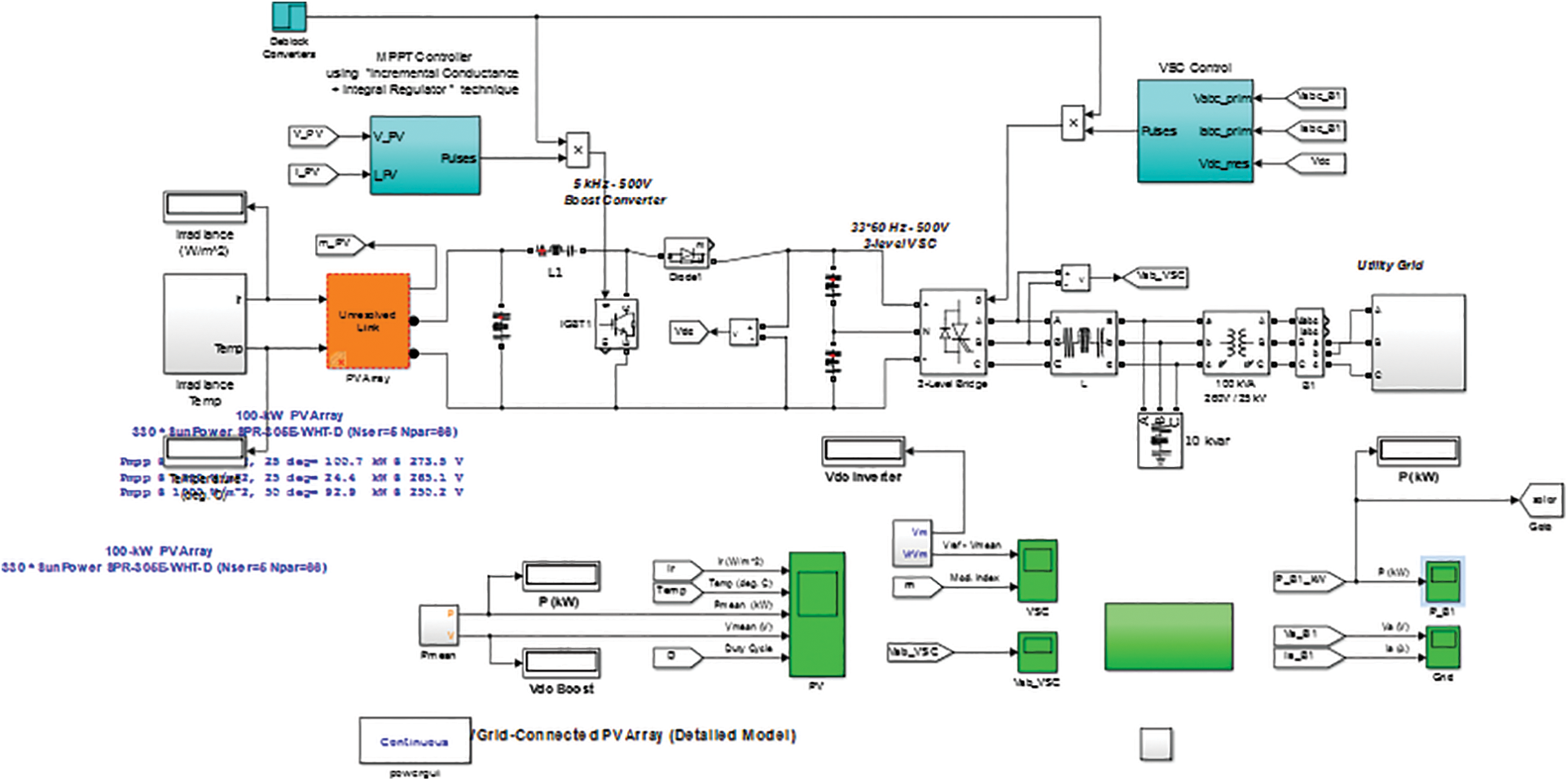
Figure 4: Simulation diagram of solar system
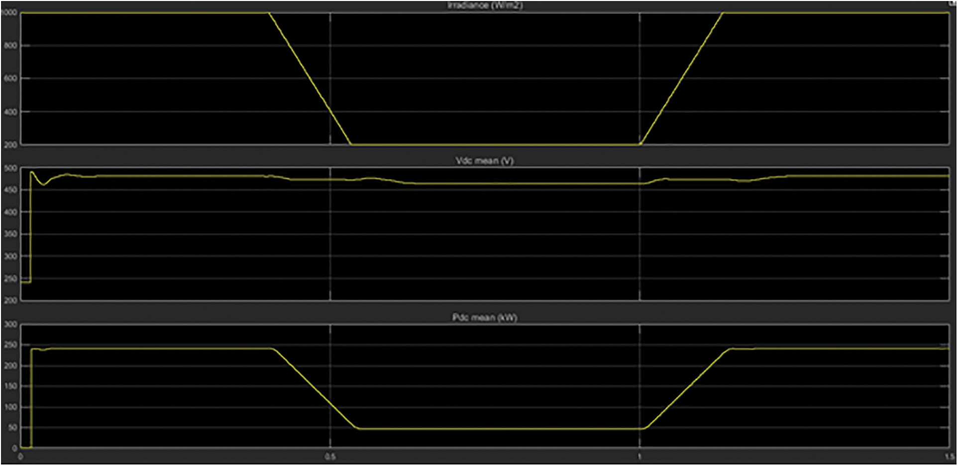
Figure 5: Solar radiation, voltage, and output power of the solar system
The modeling of the wind system is shown in Fig. 6, which illustrates the simulation performance using the average wind speed of 15 kilometer per hour. The wind system generates the AC three-phase power, and it can be transferred, although the wind system is an AC power output. So, the output has to convert with an equal magnitude to the hybrid system. The DC-DC boost converter is the purpose of stepping up the voltage for the utility. The results show that from 15 KW of windmills (five windmills each rated 3 KW), 36 KW of electricity is generated per day when it operates under average conditions. Fig. 7 illustrates that the wind system’s voltage, current, and power, the Vabc and Iabc are 1 pu and 1 pu, respectively. The real power (P), reactive power (Q), DC link voltage, and turbine speed are shown. The wind turbines require a minimum wind speed (about 12–14 km/h) to begin spinning and producing power. High winds (50–60 km/h) are required to generate at maximum capacity. Winds less than 90 km/h; the turbines must be shut down to prevent damage at that speed.
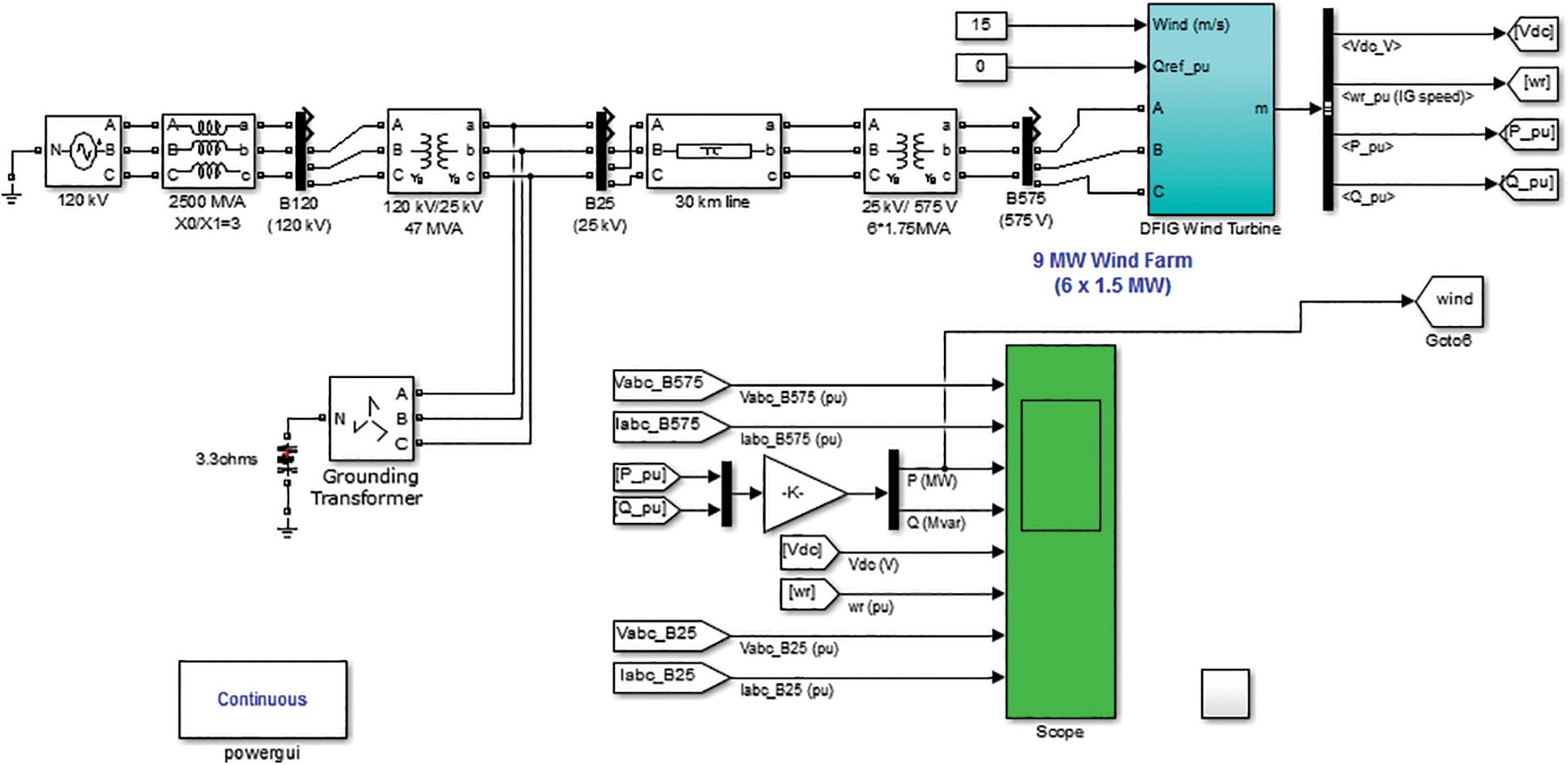
Figure 6: Simulation diagram of the wind system
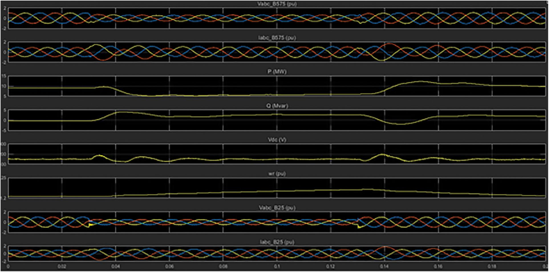
Figure 7: Voltage, current, and power waveform of the wind system
The diesel system (shown in Fig. 8) is generally used only in emergency conditions to block out power or power failure from the main power grid. DGs provide superior fuel efficiency since they do not use as much fuel as a gas engine to produce the same amount of power. DGs are also heavier than gas engines to withstand the increased stress of more excellent compression ratios. We are designing a 7 KW DG because our emergency need will be around 7 KW. Two and a half to three liters of diesel are required to generate 7 KW. Fig. 9 shows the DG’s stator current, output power, and mechanical power, typically 1 pu, 1000 W, and 0.1 pu, respectively.
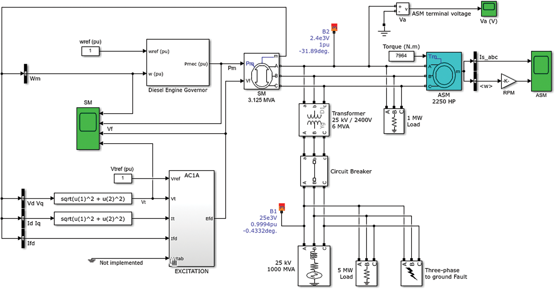
Figure 8: Simulation diagram of the diesel system
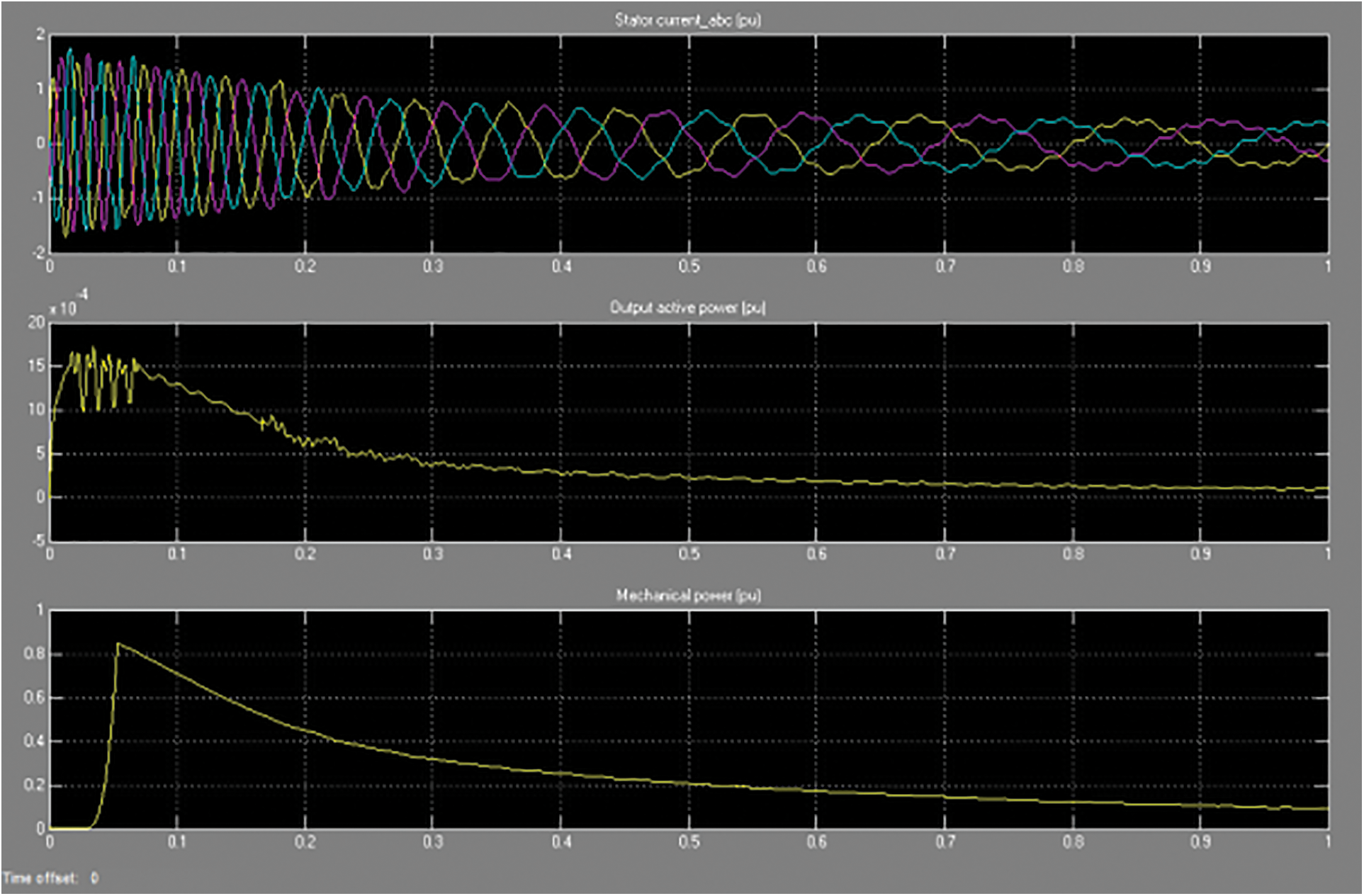
Figure 9: (a) Stator current_abc in pu, (b) Output active power in pu, and (c) Mechanical power in pu of the DG set
5.4 Modelling of Microgrid (Solar, Diesel, Wind, and Eb Source)
The MATLAB/SIMULINK software is used to reproduce the complete hybrid renewable energy system architecture of the solar power, wind power, electricity board, and DG system, shown in Fig. 10. A grouping of those resources into a hybrid power generation process will boost their efficiency by raising their whole energy output and minimizing the need for storing energy. Initially, the solar power system delivers the load to the residential, and the wind power system takes charge by means of a switching controller when the solar power does not exist. The utility grid starts to function with the assistance of a designed logic controller when both solar and wind power are insufficient to convene the residential demand.
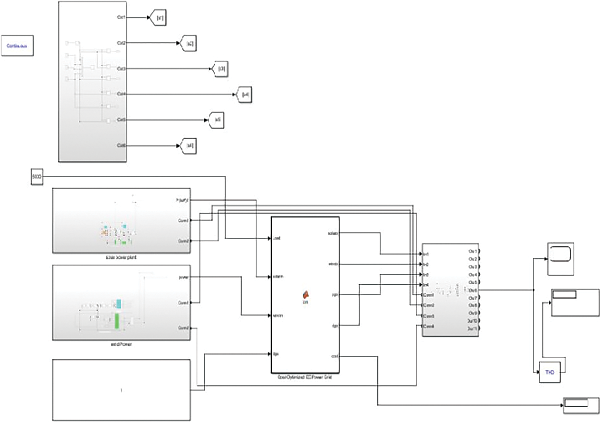
Figure 10: Modeling of microgrid (Solar, Diesel, wind, and EB source)
The designed relay controller permits a DG set to give backup power to the corresponding residential buildings when utility sources do not exist. The developed microgrid model has been tested under variable distributed power generation and residential buildings with a fixed load. Results obtained from the simulation deliver the performance of the proposed hybrid power control strategy for managing the power flow in the system. The load and grid voltage constantly maintained with respect to time is shown in Fig. 11. The system's expected performance has been achieved, and the imperfect sine waves found in the resulted waveforms reveal that the system reports power losses due to the switching process. And so, the system has to be considered to stabilize the energy waveforms.
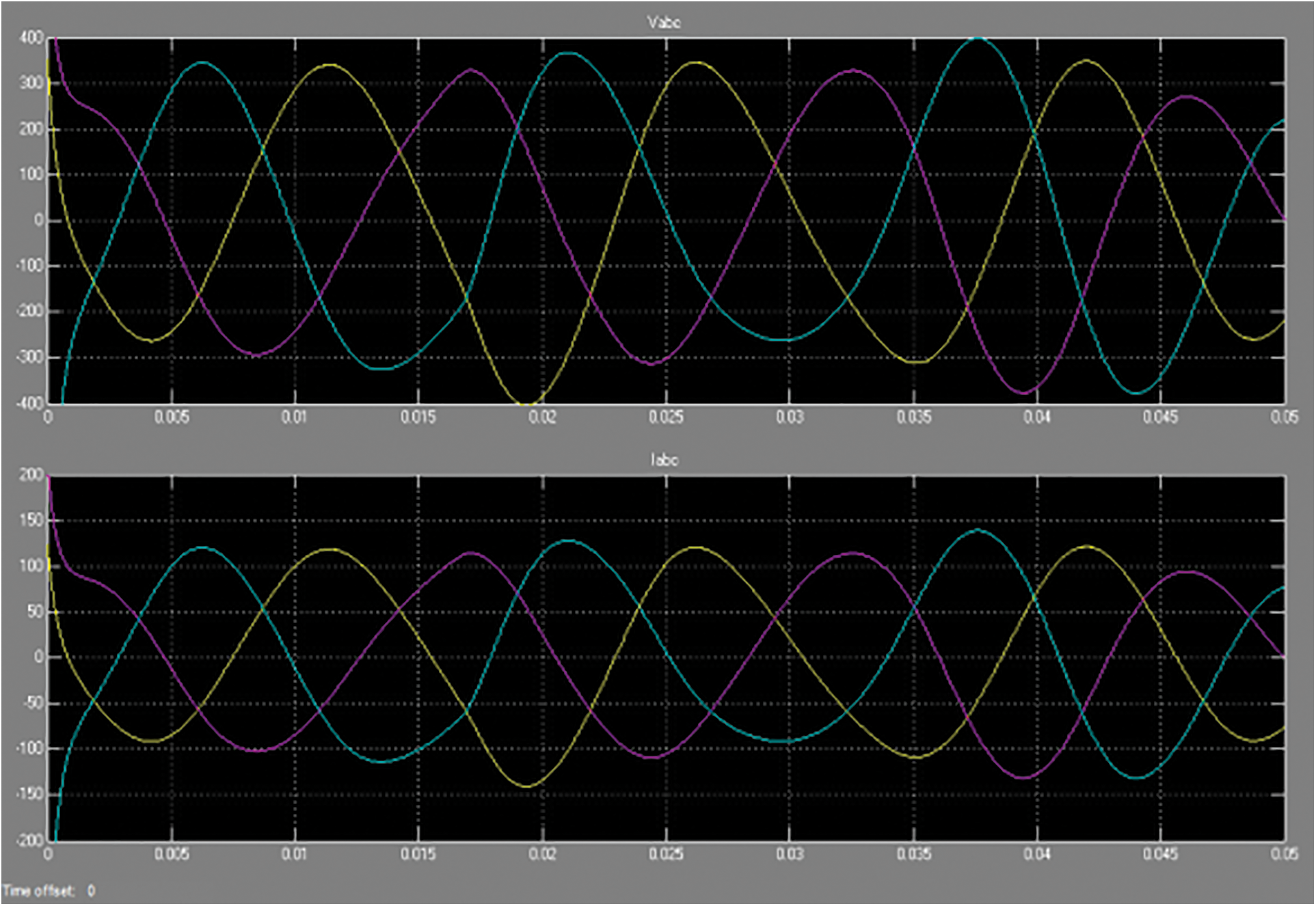
Figure 11: Shows the load voltage and load current waveforms
Fig. 11 illustrates the microgrid’s load voltage and load current, which attained 350 V and 125 A, respectively.
A residential building’s monthly demand is 13–15 MW. So, each day nearly 433 KW of electricity is required. Consider a Residential building operating for 8 h per day, and then 50–60 KW of electricity is required for each hour. Companies’ monthly electricity bills without a microgrid 13 MW of power from the power grid: For commercial connections, 1unit of power costs Rs.8 in the power grid.
Power cost : 13000 × 8 = 104000.
Compensating cost for low power factor : 55,408.
Total cost : 159,408.
To reduce the electricity bill microgrid is designed with 15 KW from solar, 10 KW from wind, and a compensating power of 15 KW from a DG.
(i) Solar system:
The power from the solar system depends on solar panel size, its efficiency, and the amount of sunlight the panel gets. The sunlight radiation varies depending on the season and climatic conditions. The given calculation is based on its average value. On average, 8 h of sunlight is considered.
Power generated per day : 15 KW × 8 =120 KW
Power generated per month : 120 KW × 30 = 3.6 MW
(ii) Wind system:
Similar to the solar system, the power output from the wind depends on the capacity of windmills, their efficiency, and wind speed. The average wind speed in Chennai is 9.8 miles per hour or 15 km per hour. The minimum speed required to turn the turbine is 12–14 km per hour. On average, wind speed turbines gives only 10% of their rated power. We are using 3 kw windmills for nearly five.
On average condition
Power generated per hour: 10% of rated power.
10% (3 kw × 5)
Power generated per day: 36 kW
Power generated per month: 1.8 MW
Total power from renewable resources: 3.6 + 1.8 = 5.4 MW
Remaining power required for the industry: 13 mw − 5.4 MW = 7.6 mw
Electricity cost: 7600 watts × 8 = Rs.60, 800
Using microgrids with multilevel inverter power factor is improved, so the company no need to pay the compensation amount for low power factor.
Cost saved per month = 159408 – 60800 = 98608.
Investment Cost:
Solar system
No. of. Panels required to produce15 KW: 46 panels
Cost of each panel (each panel produces 320 watts of power): 8,960
Total cost: 412,160
Wind system
No. of windmills (3 KW): 5
Cost of each: 195,000 lakhs
Total cost: 9, 75,000
Investment cost: 412160 + 975000 = 13, 87,160
As we are gaining Rs.98608 per month, the company can get the investment amount within 15 months.
This paper proposes a renewable-based DC microgrid with an optimized EMS. Cost optimization is performed using an intelligent control system to benefit the microgrid owners. The main problem in DC to AC conversion involves harmonics distortion. Five-stage multilevel inverter harmonics are reduced, and power quality is improved. Increasing Electricity demand cannot be controlled in developing nations. Renewable resources such as solar and wind are available everywhere, and renewable-based DC microgrids can be introduced in all companies and shopping complexes to satisfy the load demand. In the future, EMS in hybrid distributed energy resources system using meta-heuristics techniques, also one of the rarest techniques is game theory should be utilized to energy management. These techniques are pretty effective and easy to implement.
Funding Statement: The authors received no specific funding for this study.
Conflicts of Interest: The authors declare that they have no conflicts of interest to report regarding the present study.
References
1. Y. Wu, R. Wang, H. Huang and S. Deng, “Power sharing between microgrids based on a secondary market,” IEEE Systems Journal, vol. 12, no. 3, pp. 2729–2738, 2016. [Google Scholar]
2. M. H. Amrollahi and S. M. Bathaee, “Techno-economic optimization of hybrid photovoltaic/wind generation together with energy storage system in a stand-alone micro-grid subjected to demand response,” Applied Energy, vol. 202, no. 7, pp. 66–77, 2017. [Google Scholar]
3. A. M. O. Haruni, M. Negnevitsky, M. E. Haque and A. Gargoom, “A novel operation and control strategy for a standalone hybrid renewable power system,” IEEE Transactions on Sustainable Energy, vol. 4, no. 2, pp. 402–413, 2018. [Google Scholar]
4. S. Deepa and S. Rajesh babu, “A robust STATCOM controller using particle swarm optimization,” IJE Transactions B: Applications, vol. 27, no. 5, pp. 731–738, 2014. [Google Scholar]
5. C. N. Bhende, S. Mishra and S. G. Malla, “Permanent magnet synchronous generator-based standalone wind energy supply system,” IEEE Transactions on Sustainable Energy, vol. 2, no. 4, pp. 361–373, 2011. [Google Scholar]
6. W. Shi, X. Xie, C. Chu and R. Gadh, “Distributed optimal energy management in microgrids,” IEEE Transactions on Smart Grid, vol. 6, no. 3, pp. 1137–1146, 2015. [Google Scholar]
7. V. Gajula and R. Rajathy, “An explorative optimization algorithm for sparse scheduling in-home energy management with smart grid,” Circuit World, vol. 46, no. 4, pp. 335–346, 2020. [Google Scholar]
8. N. Augustine, S. Suresh, P. Moghe and K. Sheikh, “Economic dispatch for a microgrid considering renewable energy cost functions,” IEEE PES Innovative Smart Grid Technologies, Washington, DC, USA, pp. 1–7, 2012. [Google Scholar]
9. S. Deepa, N. Anipriya and R. Subbulakshmy, “Design of controllers for continuous stirred tank reactor,” International Journal of Power Electronics and Drive System, vol. 5, no. 4, pp. 576–582, 2015. [Google Scholar]
10. M. F. Zia, E. Elbouchikhi and M. Benbouzid, “Microgrids energy management systems: A critical review on methods, solutions, and prospects,” Applied Energy, vol. 222, no. 6, pp. 1033–1055, 2018. [Google Scholar]
11. C. L. Thiel, N. Campion, A. E. Landis, A. K. Jones, L. A. Schaefer et al., “A materials life cycle assessment of a net-zero energy building,” Energies, vol. 6, no. 2, pp. 1125–1141, 2013. [Google Scholar]
12. S. K. Kim, J. H. Jeon, C. H. Cho, J. B. Ahn and S. H. Kwon, “Dynamic modeling and control of a grid-connected hybrid generation system with versatile power transfer,” IEEE Transactions on Industrial Electronics, vol. 55, no. 4, pp. 1677–1688, 2008. [Google Scholar]
13. E. Pyloudi, S. Papantoniou and D. Kolokotsa, “Retrofitting an office building towards a net zero energy building,” Advances in Building Energy Research, vol. 9, no. 1, pp. 20–33, 2015. [Google Scholar]
14. S. Abhishek, M. Priya and G. Rachana, “Analysing the impact of various incentives on solar tariff in India,” International Journal of Sustainable Energy, vol. 41, no. 2, pp. 126–147, 2020. [Google Scholar]
15. M. Alizadeh Bidgoli, A. R. Payravi, A. Ahmadian and W. Yang, “Optimal day-ahead scheduling of autonomous operation for the hybrid micro-grid including PV, WT, diesel generator, and pump as turbine system,” Journal of Ambient Intelligence and Humanized Computing, vol. 12, no. 1, pp. 961–977, 2020. [Google Scholar]
16. U. Zafar, S. Bayhan and A. Sanfilippo, “Home energy management system concepts, configurations, and technologies for the smart grid,” IEEE Access, vol. 8, pp. 119271–119286, 2020. [Google Scholar]
17. A. Mohamed, T. Jin and W. Su, “An effective stochastic framework for smart coordinated operation of wind park and energy storage unit,” Applied Energy, vol. 272, no. 2, pp. 1–13, 2020. [Google Scholar]
Cite This Article
 Copyright © 2023 The Author(s). Published by Tech Science Press.
This work is licensed under a Creative Commons Attribution 4.0 International License , which permits unrestricted use, distribution, and reproduction in any medium, provided the original work is properly cited.
 Downloads
 Citation Tools