
 Submit a Paper
 Propose a Special lssue
 Open Access
ARTICLE

Deep Learning-Based FOPID Controller for Cascaded DC-DC Converters
1 Department of EEE, Vel Tech Rangarajan Dr. Sagunthala R&D Institute of Science and Technology, Chennai, 600062, India
2 Department of EEE, R. M. K. Engineering College, Kavaraipettai, Chennai, 601206, India
* Corresponding Author: S. Hema. Email:
Computer Systems Science and Engineering 2023, 46(2), 1503-1519. https://doi.org/10.32604/csse.2023.036577
Received 05 October 2022; Accepted 22 November 2022; Issue published 09 February 2023
 View Full Text
 Download PDF
Abstract
Smart grids and their technologies transform the traditional electric grids to assure safe, secure, cost-effective, and reliable power transmission. Non-linear phenomena in power systems, such as voltage collapse and oscillatory phenomena, can be investigated by chaos theory. Recently, renewable energy resources, such as wind turbines, and solar photovoltaic (PV) arrays, have been widely used for electric power generation. The design of the controller for the direct Current (DC) converter in a PV system is performed based on the linearized model at an appropriate operating point. However, these operating points are ever-changing in a PV system, and the design of the controller is usually accomplished based on a low irradiance level. This study designs a fractional-order proportional-integrated-derivative (FOPID) controller using deep learning (DL) with quasi-oppositional Archimedes Optimization algorithm (FOPID-QOAOA) for cascaded DC-DC converters in micro-grid applications. The presented FOPID-QOAOA model is designed to enhance the overall efficiency of the cascaded DC-DC boost converter. In addition, the proposed model develops a FOPID controller using a stacked sparse autoencoder (SSAE) model to regulate the converter output voltage. To tune the hyper-parameters related to the SSAE model, the QOAOA is derived by the including of the quasi-oppositional based learning (QOBL) with traditional AOA. Moreover, an objective function with the including of the integral of time multiplied by squared error (ITSE) is considered in this study. For validating the efficiency of the FOPID-QOAOA method, a sequence of simulations was performed under distinct aspects. A comparative study on cascaded buck and boost converters is carried out to authenticate the effectiveness and performance of the designed techniques.Keywords
Renewable energy is considered increasingly significant and predominant in distribution systems that offer various options to electricity users either to get electricity from the chief electricity source or framing a micro-source not just to satisfy the requirement but also to be an energy producer which supplies a microgrid [1]. When a microgrid is disconnected from or connected to the larger grid, it can do so reliably and autonomously thanks to its many individual micro sources and loads [2]. The micro-source can be divided, either as a high-frequency ac source or a dc source [3]. These two micro-source categories contain different renewable energy applications, like reciprocating engines, solar cell modules, wind turbines, and fuel cell stacks. Micro-grid units are delivered by several micro sources; the high step-up converters can be utilized for increasing the output voltage of a micro source to 380–400 V for dc interfaces to a primary electrical source via the Direct Current (DC) to alternating current (AC) inverter [4]. The fuel cell stack, as well as the single solar cell module, were low-voltage resources, and therefore, a high step-up voltage gain DC-DC converter was needed for regulating the voltage of DC-DC interfaces [5].
Scientific research works were widely concentrating on the use of DC-DC converters having diverse output volt values; hence, Buck-Boost, Buck, Boost, and many other types of DC-DC converters are suggested [6]. DC-DC converters having high voltage converting ratios contain a wide range of applications in hydropower plants, industrial equipment, vacuum discharge lamps, including electric vehicles, light emitting diode (LED) drivers, and renewable energy resources like wind turbines, solar cells, and fuel cells [7]. Voltage control is established with the help of power electronic DC-DC converters in an extensive range of applications. Making reliable and robust controllers addressing the frequency and transient response needs becomes complex for such converters [8].
A controller focuses on producing an output voltage that stays in a defined range of current fluctuation and load voltage step changes. With an adjustment made to the duty cycle applied to a switching gadget, DC-DC converters can also step down or up the input voltages depending on the specification of the applied load [9]. Numerous control techniques which generate a controlled voltage output are scrutinized with distinct stages of efficiency in present research works. Owing to the easy Implementation of the proportional integral and derivative (PID) controller, it was the most frequently utilized technique in the industry [10]. However, for some topologies such as the zeta converter, which was a fourth-order system, devising a PID controller becomes complex and the model order reduction approach can be used for regulating the converter’s ant colony optimization-related PID controller.
This study designs a fractional-order proportional-integrated-derivative (FOPID) controller using a quasi-oppositional Archimedes Optimization algorithm (FOPID-QOAOA) for cascaded DC-DC converters in microgrid applications. The presented FOPID-QOAOA model is designed to enhance the overall efficiency of the cascaded DC-DC boost converter. In addition, the proposed model designs a FOPID controller using a stacked sparse autoencoder (SSAE) model to regulate the converter output voltage. To tune the hyper-parameters related to the SSAE model, the QOAOA is derived by the including of the quasi-oppositional based learning (QOBL) with traditional AOA. Furthermore, an objective function with the inclusion of the integral of time multiplied by squared error (ITSE) is considered in this study. For validating the efficiency of the FOPID-QOAOA method, a sequence of simulations was performed under distinct aspects.
Patel et al. [11] present an adaptive power flow management method for a standalone hybrid renewable energy system (HRES) that indulge load management, photovoltaic (PV) cell, and battery energy storage (BES). A multistage FOPID (multistage FOPID) controller can be suggested in the voltage-controlled loop of a bidirectional DC-DC converter that can be enhanced by a modified sine cosine algorithm. In [12], the approximation of a FOPID controller can be suggested for controlling a DC-DC converter. The tuning process and synthesis of the non-integer PID controller were explained step by step. The suggested technique considers desired closed-loop features and sturdiness, which keeps the tuning procedure simple. The transfer operation of the FOPID and its time domain depiction were analyzed and described.
Tiwari et al. [13] performed modeling of a Dual Active Bridge (DAB) kind converter Generalized Average Modelling. This kind of process considers the DC and harmonic effect of the alternative voltage. To control, parameters of fractional order (FO) controllers, such as Tilt Integral Derivative (TID) and FOPID were synthesized by making use of the heuristic optimizing methods, also termed genetic algorithm (GA). The usage of fuzzy-based controllers allows more plant controllability when compared with traditional integer order controllers. Yousef et al. [14] present a hybrid PV, wind turbine, and battery storage system linked to a 3-stage grid. Three kinds of controllers were taken, and a comparison was made for an HRES, like the fractional order integral control (FIC), proportional-integral (PI), and FOPI.
Djebbri et al. [15] recommend a supervision strategy based on a fractional order reference adaptive control (FO-MRAC) model for the control of electrical power transformation in a multisource renewable energy mechanism. Two source systems (lead-acid battery bank and PV) are considered to have a particular zero-volt switch full-bridge isolated buck DC-DC energy converters, and the load was resistive. The global power systems, including coupled DC-DC converters on a DC bus, were precisely modeled in the state space field. In [16], Therefore, an improvised single-ended primary inductance converter (SEPIC) can be suggested with a brushless DC (BLDC) motor drive. The advanced SEPIC converters were projected with switched inductors, and their control topologies can be examined with the FOPID controller having an ant-lion optimizer (ALO) technique.
Numerous studies have concentrated on the design of controllers for DC-DC energy converters that have been available in the literature. Despite the machine learning (ML) and deep learning (DL) models that existed in earlier studies, it is still needed to enhance performance. However, it remains a challenging problem. Overfitting occurs when there are too many parameters for the given DL model, which is made worse by the model’s gradual deepening. At the same time, different hyper parameters have a significant impact on the effectiveness of the DL model training phase, particularly the learning rate. It is also necessary to modify the learning rate parameter obtains better performance. Therefore, in this study, authors employ the QOAOA technique for the hyper-parameter tuning of the SSAE model.
All of the above controller layouts for the direct Current (DC) converter in a PV system are carried out based on the linearized model at an appropriate operating point, based on the above-mentioned study carried out in the DC-DC converter. However, in a PV system, these operating points are constantly shifting, so the controller is typically designed using low irradiance levels.
The buck and boost converter consists of a (C) capacitor, (S) controllable switch, (L) inductor, (D) diode, (R) resistive load, and (E) input DC supply voltage [17]. The converter can be operated in CCM and DCM modes. Then, derive the Continuous Conduction Mode (CCM) mode directly from the Discontinuous Conduction Mode (DCM). There are three regions for converters to operate in DCM modes. The region is considered as the inductor current waveform and switches status in the following:
If
Fig. 1 illustrates a cascaded system using two DC-DC boost converters (step-up) or buck converters (step-down). The initial converter is called a source converter, and the successive converter is named a load converter. In this study, the system Maximal Power Point Tracker (MPPT) information is considered a significant factor. The state space averaged model of the interacted converter is represented as DCM operation mode [18]. The cascade buck converter is determined by:
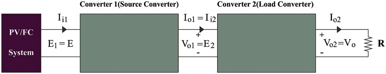
Figure 1: Cascaded DC-DC converter
Cascade boost converter is given by:
The equation,
In this study, a new FOPID-QOAOA technique was developed for cascaded DC-DC converters in microgrid applications. The presented FOPID-QOAOA model is designed to enhance the overall efficiency of the cascaded DC-DC boost converter. The proposed model designs a FOPID controller using QOAOA based SSAE model to regulate the converter output voltage.
The construction of the FOPID controller is a linear PID controller extension used in various applications [19]. The architecture of the presented model has been demonstrated in Fig. 2. As illustrated,
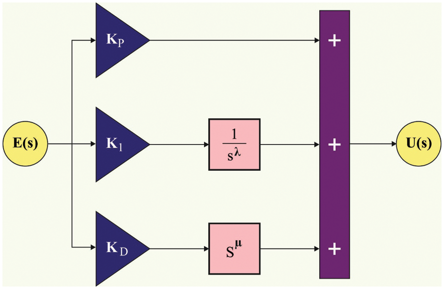
Figure 2: FOPID controller
Fig. 2 depicts the workflow of the FOPIC controller. The conventional PID controller based on fractional calculus is expanded by the fractional order PID (FOPID) controller. Proportional, integral, and derivative (PID) controllers have been widely utilized in industry for process control for a long time. Their merits include a straightforward design and good performance, such as little settling time and low percentage overshoot (essential for slow industrial processes). PID controllers are of utmost importance, so ongoing efforts are made to increase their reliability and quality. Fractional order controllers, a generalization of traditional integer order controllers, would produce more accurate and reliable control performances in the field of automatic control.
4.2 Architecture of SSAE Model
In the proposed model, the SSAE-based FOPID controller is designed to regulate the converter output voltage. SSAE refers to the field of deep learning, and its core component is sparse auto-encoder (SAE). With the incorporation of reconstruction errors and sparse penalty in the coding layer, SAE could efficiently encourage the model to learn the data feature and copy the input to output. Generally, SAE is applied in feature extraction, and the feature is employed in clustering or classification algorithm. But SAE could not attain in-depth data features because it only has a single layer [20]. So, SSAE is projected by adding the previous SAE’s concealed state to the next SAE’s input. The lower-level feature of the information is continuously combined, and finally, easily identifiable higher-level feature representation can be achieved. Autoencoder (AE), as a type of neural network, manages to copy the input to output after training. The network seems to have the subsequent two parts: an encoder module
and a decoder module
For
4.3 Design of QOAOA-Based Hyperparameter Optimization
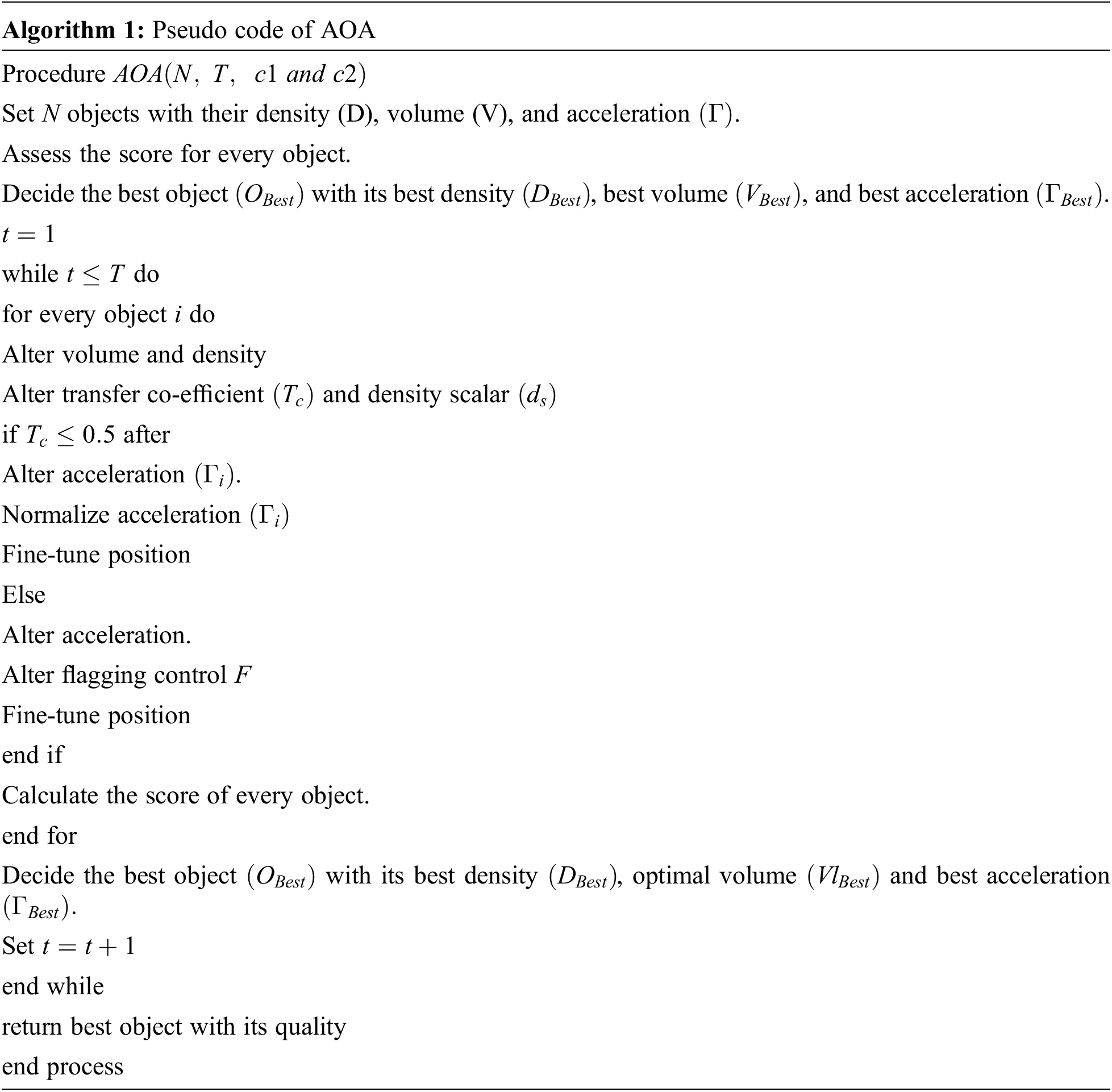
The QOAOA is derived by the inclusion of the QOBL with traditional AOA. A new population-based metaheuristic approach named AOA algorithm is developed. Like other population-based techniques, AOA follows the initial stage to generate an evaluation of the population, random population as well as update parameters in exploration and exploitation stages and termination stage.
In starting stage, every item was assumed to be arbitrarily positioned. The item is treated as the search variable or population, and the position is generated arbitrarily within the upper and lower bounds. By assuming the item number as the
In Eq. (9),
Finally, the fitness function is estimated to determine the best item and its ideal value (FF) as
In the parameter updating |stage, the volume, and density of
From the expression,
In Eq. (13), it and
The exploration phase is introduced a collision takes place between items. It is considered that the collision of the item occurs for TO ≤ 0.5, and those item experiences acceleration, as upgraded by the random material (
Here,
The exploitation phase is projected once the item, is not subject to collision, viz., TO > 0.5, and thus the acceleration of
In the transformation stage, the percentage of step changes that every item gains in the exploitation and exploration stages are modeled within the interval of [L, U] as follows:
The upper and lower normalization ranges were fixed as 0.1 and 0.9, correspondingly. The item is generally in an exploration stage if
where,
To increase the effectiveness of AOA approach, the QOAOA model is derived from the concept of QOBL. QO-assisted learning mechanism allows one to achieve a solution candidate with the considering of the current population alongside quasi-opposite population. The random population initialized by the AOA approach, is replaced with a quasi-opposite number. Furthermore, it is guaranteed that the quasi-opposite number is near the opposite point to the solution. Here, the QOAOA procedure is derived from the QOBL-based population, initialization method. For an opposite number in
It is likely that the very efficient candidate solution is derived from the QOAOA approach, and it accomplishes the better solution candidate. The quasi-opposite position could increase the initial population quality and make the search technique fast by finding the powerful region in the search space.
In this study, the FOPID-QOAOA technique derives an objective function with the inclusion of the integral of time multiplied by squared error (ITSE) is taken into account. The objective function has a considerable effect on the performance of the presented DC-DC converters and the optimum tuning of the controller coefficient [21]. A closed-loop control system’s effectiveness is assessed by a performance index acquired from the error signals. The system parameter is attuned under optimal control to decrease these indexes. As a result, the aim of creating a robust controller is to improve response by diminishing time-domain features. To accomplish optimum controller parameters, the objective function must be determined in such a way that the dynamic system responses have the minimum amount of undershoot and overshoot possibility and lower settling time.
In this work, the integral of absolute error can be determined as evaluation functions, the integral of time multiplied by squared error (ITSE) is determined by the integral of squared error (ISE), the objective function, and the integral of time multiplied by absolute error (ITAE). The mathematical expression of objective and evaluation functions are given below:
To verify the efficiency of FOPID and PID controllers, the cascaded DC-DC boost converter control structure is simulated in version 2019b of MATLAB/Simulink software on an intel-corei7/16GB DDR3 personal computer. In different circumstances and scenarios, the FOPID controller’s performance is compared to the PID controller.
Table 1 and Fig. 3 show the output voltage attained by the proposed model in case-1. This study simulates the proposed cascaded boost converter at a 50% duty cycle (D = 0.5). This case aims to examine the DC-DC output voltage using FOPID and PID controllers. In this scenario, the input voltage is 20 volts, and the output voltage should be 80 volts.
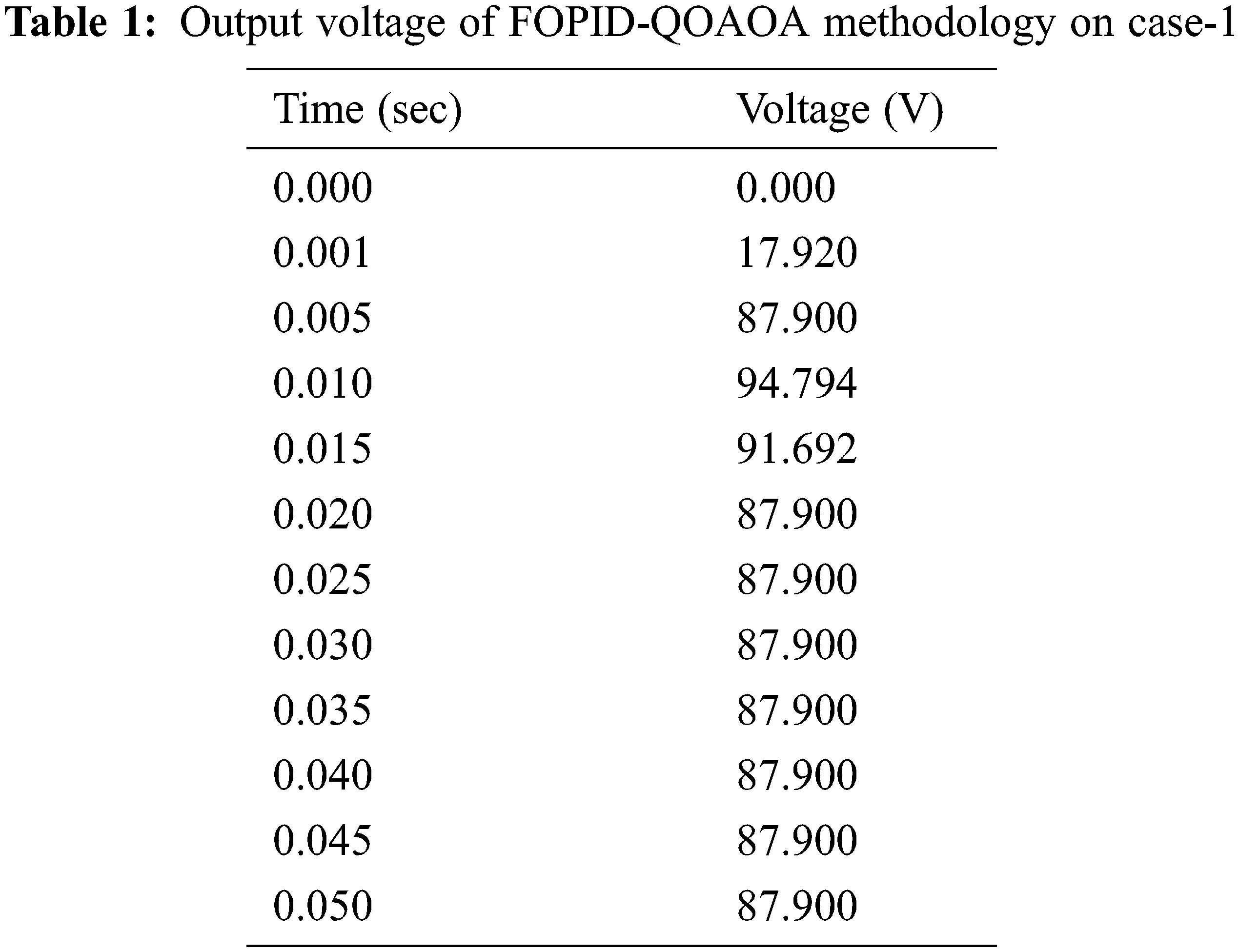
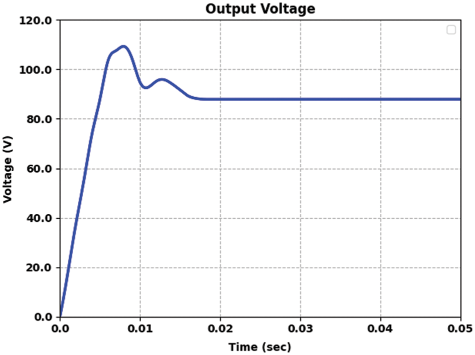
Figure 3: Output voltage attained by FOPID-QOAOA model on case 1
Table 2 and Fig. 4 provide the voltage output offered by the FOPID-QOAOA model on two controllers under case 1. The results implied that the FOPID-QOAOA model has effectively designed the controller under all aspects. For instance, with time duration of 0.005 s, the output voltage of FOPID and PID controllers are 54.722 and 41.648 V, respectively. Also, with a time duration of 0.015 s, the output voltage of FOPID and PID controllers are 81.173 and 78.437 V, correspondingly. Furthermore, with time duration of 0.035, the output voltage of FOPID and PID controllers are 81.653 and 81.653 V, correspondingly. Furthermore, with time duration of 0.050 s, the output voltage of FOPID and PID controllers are 81.653 and 81.653 V, correspondingly.
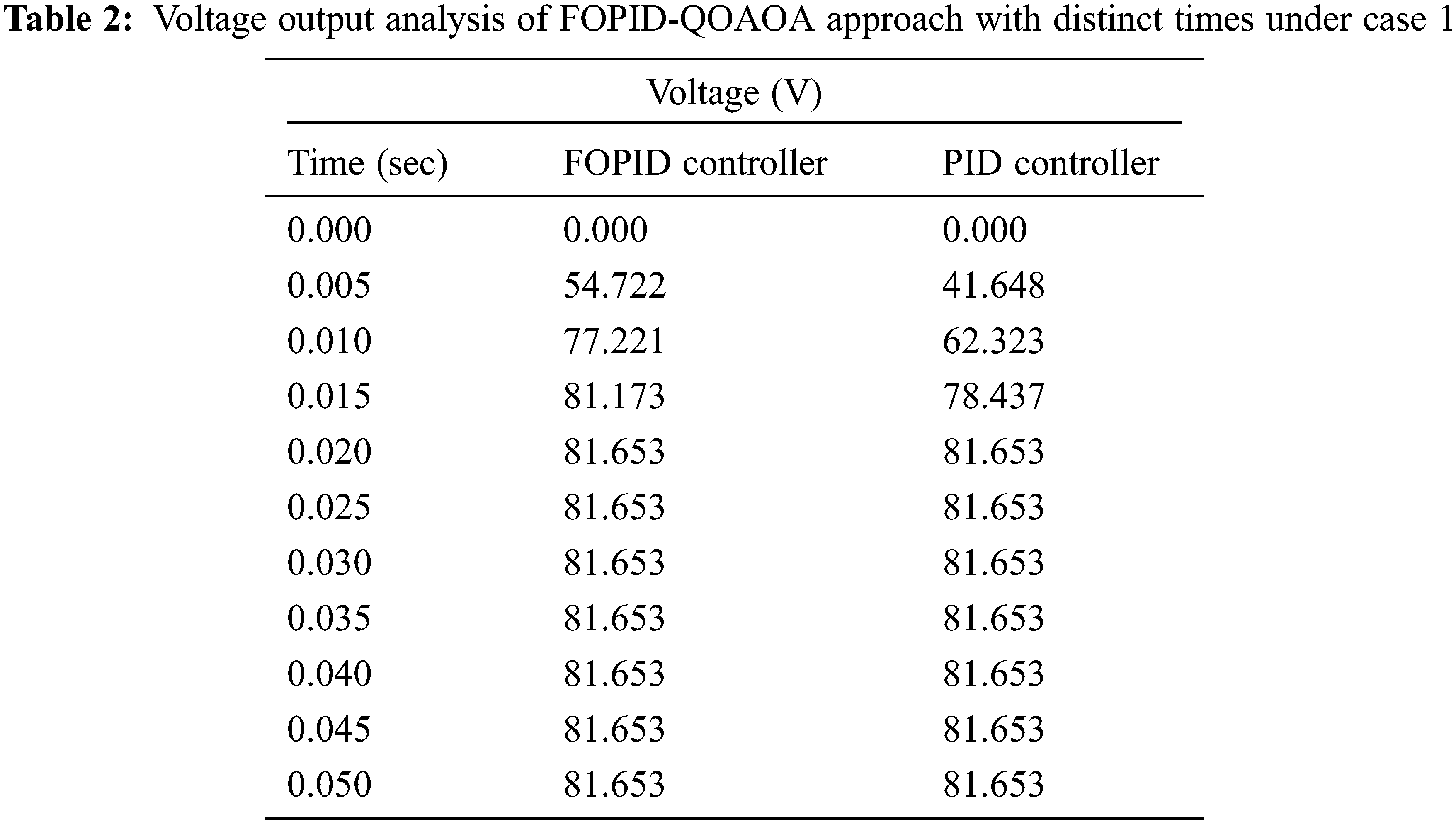
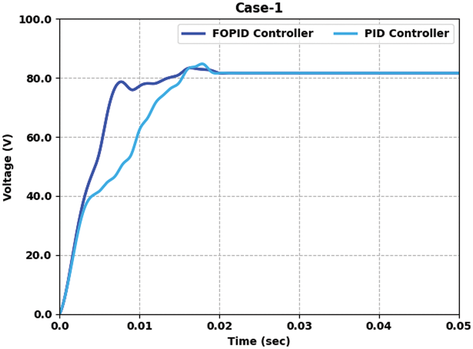
Figure 4: Voltage output analysis of FOPID-QOAOA method under case 1
Table 3 and Fig. 5 provide the voltage output offered by the FOPID-QOAOA model on two controllers under case 2. The results implied that the FOPID-QOAOA model has efficiently designed the controller under all aspects. For the sample, with a time duration of 0.005 s, the output voltage of FOPID and PID controllers are 78.965 and 62.051 V, correspondingly. Also, with a time duration of 0.015 s, the output voltage of FOPID and PID controllers are 83.119 and 86.086 V, correspondingly. Furthermore, with a time duration of 0.035 s, the output voltage of FOPID and PID controllers are 83.415 and 84.009 V, correspondingly. Moreover, with a time duration of 0.050 s, the output voltage of FOPID and PID controllers are 83.415 and 84.009 V, correspondingly.
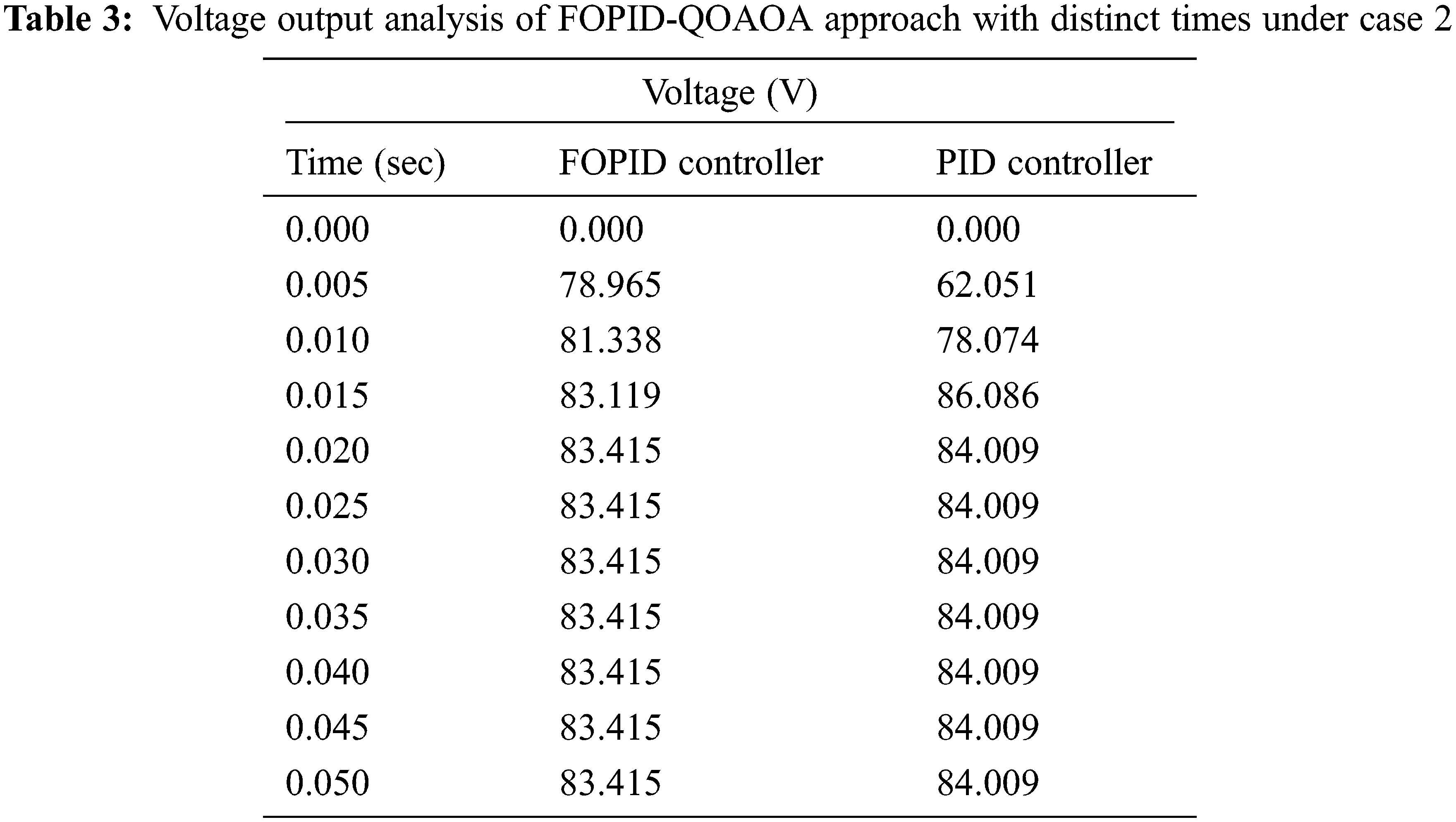
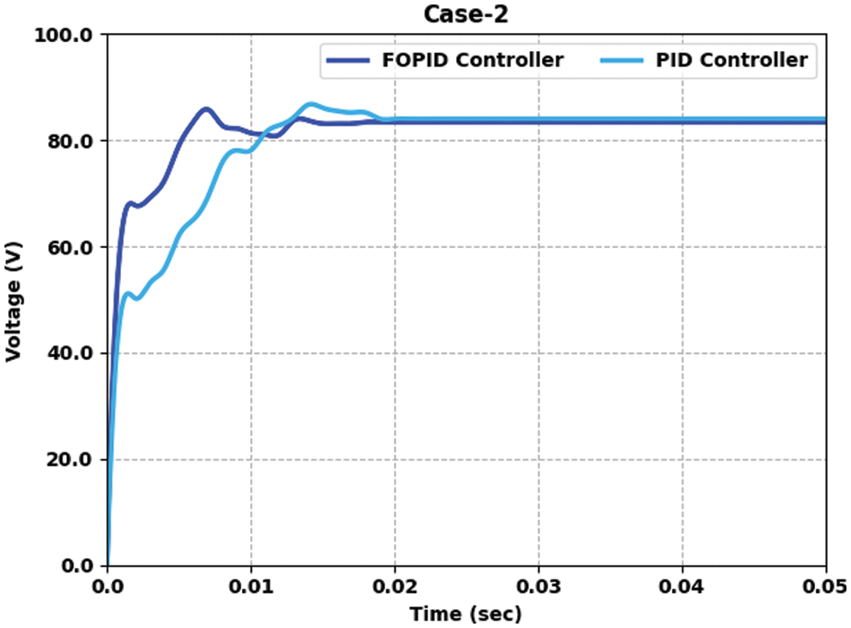
Figure 5: Voltage output analysis of FOPID-QOAOA approach under case 2
Table 4 and Fig. 6 offer the voltage output provided by the FOPID-QOAOA approach on two controllers under case 3. The results show that the FOPID-QOAOA model has efficiently developed the controller in every aspect. For example, with a time duration of 0.005 s, the output voltage of FOPID and PID controllers are 77.486 and 64.171 V, correspondingly. As well, with time duration of 0.015 s, the output voltage of FOPID and PID controllers are 87.546 and 88.434 V, correspondingly. Furthermore, with a time duration of 0.035 s, the output voltage of FOPID and PID controllers are 87.546 and 94.648 V, correspondingly. Moreover, with time duration of 0.050 s, the output voltage of FOPID and PID controllers are 89.914 and 86.067 V, correspondingly.

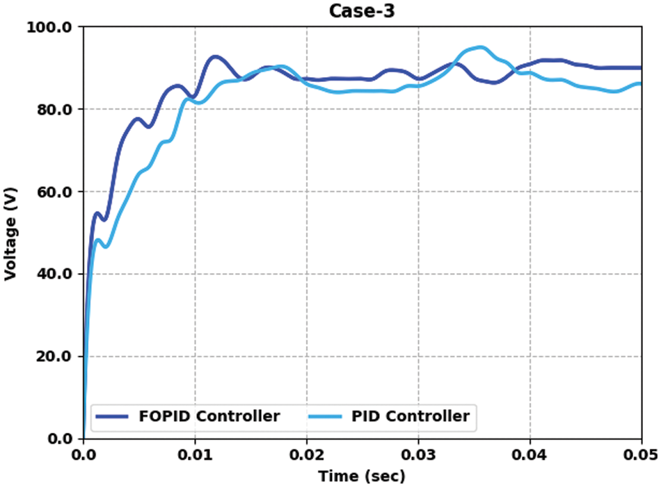
Figure 6: Voltage output analysis of FOPID-QOAOA approach under case 3
The time domain characteristics obtained by the FOPID-QOAOA model under PID and FOPID controller are given in Table 5. The results implied that the FOPID-QOAOA model has accomplished effectual time domain values under distinct aspects. For example, under ITSE, the FOPID-QOAOA model has offered an overshoot of 86.14 and 86.21 under FOPID and PID controllers correspondingly. Finally, under ISE, the FOPID-QOAOA model has offered an overshoot of 85.38 and 88.75 under FOPID and PID controllers correspondingly. Furthermore, under ITAE, the FOPID-QOAOA model has offered overshoots of 87.75 and 89.50 under FOPID and PID controllers correspondingly. Simultaneously, under IAE, the FOPID-QOAOA model has provided overshoot of 87.69 and 92.11 under FOPID and PID controllers correspondingly.

Fig. 7 provides a detailed comparative total harmonic distortion (THD) inspection of the FOPID-QOAOA model with existing models such as perturb and observe (P&O), particle swarm optimization, multi-objective PSO (MPSO), ant colony optimization (ACO), grey wolf optimization (GWO), and cuckoo search optimization (CSO) algorithms. The figure implied that FOPID-QOAOA model had shown effectual outcomes with minimum THD values. For example, with case 1, the FOPID-QOAOA model has obtained lower THD of 38.12, whereas, the P&O, PSO, MPSO, ACO, GWO, and CSO models have resulted in increased THD of 40.48%, 47.51%, 47.27%, 47.06%, 46.63%, and 45.78% respectively. Simultaneously, with case 2, the FOPID-QOAOA approach has attained a lower THD of 33.72, whereas the P&O, PSO, MPSO, ACO, GWO, and CSO models have resulted in an increased THD of 42.06%, 46.36%, 45.48%, 45.13%, 44.76%, and 42.39% correspondingly. Meanwhile, with case 3, the FOPID-QOAOA model has obtained lower THD of 30.38 whereas the P&O, PSO, MPSO, ACO, GWO, and CSO models have resulted in increased THD of 41.38%, 35.05%, 34.43%, 31.14%, 33.78%, and 32.32% correspondingly.
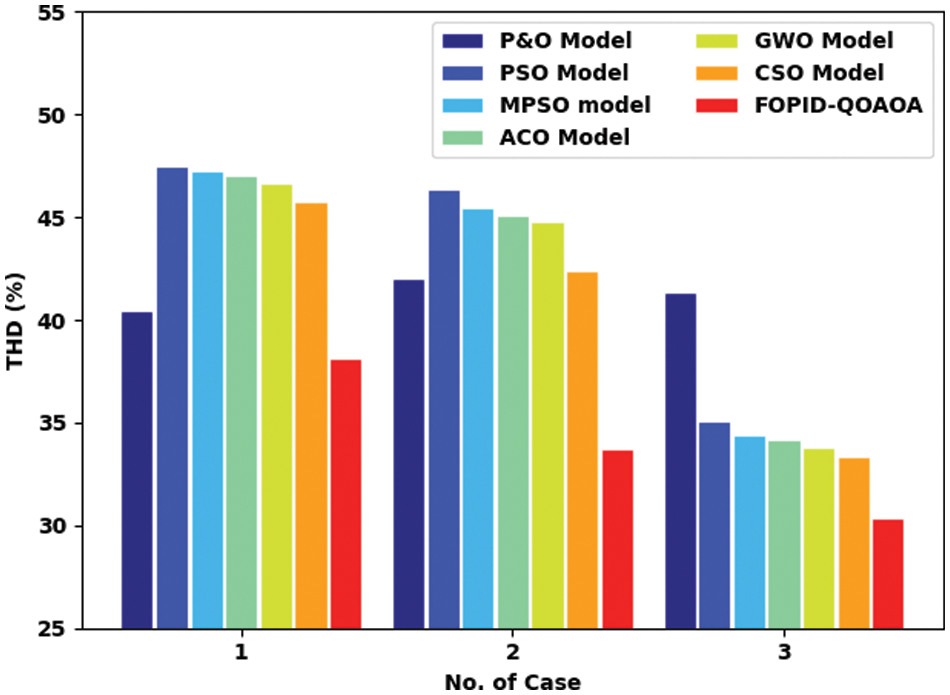
Figure 7: THD analysis of FOPID-QOAOA approach with existing methodologies
A detailed voltage profile (Vp) examination of the FOPID-QOAOA model with recent models is made in Fig. 8. The results represented the betterment of the FOPID-QOAOA model with increasing values of Vp. For example, with case 1, the FOPID-QOAOA method has improved Vp of 29.35 V whereas the P&O, PSO, MPSO, ACO, GWO, and CSO models have gained reduced Vp of 25.15, 26.3, 27.16, 27.43, 27.84, and 28.10 V correspondingly. Additionally, with case 2, the FOPID-QOAOA method has improved Vp of 30.68 V while the P&O, PSO, MPSO, ACO, GWO, and CSO models have gained reduced Vp of 24.64, 25.52, 27.57, 27.79, 28.18, and 28.25 V correspondingly. Last, with case 3, the FOPID-QOAOA model has improved Vp of 29.87 V while the P&O, PSO, MPSO, ACO, GWO, and CSO models approaches have gained reduced Vp of 24.6, 26.84, 26.91, 27.07, 27.55, and 27.94 V correspondingly. From the detailed fallouts and discussion, it is ensured that the FOPID-QOAOA model has shown effectual performance in all aspects.
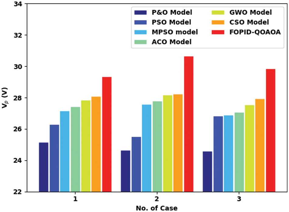
Figure 8: Voltage profile analysis of FOPID-QOAOA approach with existing methodologies
In this article, a new FOPID-QOAOA algorithm was devised for cascaded DC-DC converters in microgrid applications. The presented FOPID-QOAOA model is designed to enhance the overall efficiency of the cascaded DC-DC boost converter. In addition, the proposed model designs a FOPID controller using SSAE model to regulate the converter output voltage. To tune the hyperparameters related to the SSAE model, the QOAOA is utilized in this study. Moreover, an objective function with the inclusion of ITSE is considered in this study. For validating the efficiency of the FOPID-QOAOA method, a sequence of simulations was performed under distinct aspects. Comparative simulations were performed on cascaded buck and boost converters to validate the efficiency and performance of the devised algorithms. The FOPID-QOAOA method has improved Vp of 29.35 V whereas the P&O, PSO, MPSO, ACO, GWO, and CSO models have gained reduced Vp of 25.15, 26.3, 27.16, 27.43, 27.84, and 28.10 V correspondingly. In future, the presented model can be extended to predict the sub-harmonic instabilities. Besides, the switching regulator control parameters like amplitude of the ramp modulator or controller gain can be adjusted based on the operating point to avoid jeopardizing the effect of the instability issues, which can be adjusted depending on the maximum irradiance level.
Funding Statement: The authors received no specific funding for this study.
Conflicts of Interest: The authors declare that they have no conflicts of interest to report regarding the present study.
References
1. S. Ranganathan and A. N. D. Mohan, “Formulation and analysis of single switch high gain hybrid dc to dc converter for high power applications,” Electronics, vol. 10, no. 19, pp. 2445, 2021. [Google Scholar]
2. Z. Liu, J. Du and B. Yu, “Design method of double-boost dc/dc converter with high voltage gain for electric vehicles,” World Electric Vehicle Journal, vol. 11, no. 4, pp. 64, 2020. [Google Scholar]
3. S. Chandrasekaran, S. Durairaj and S. Padmavathi, “A performance improvement of the fuzzy controller-based multi-level inverter-fed three-phase induction motor with enhanced time and speed of response,” Journal of Electrical Engineering & Technology, vol. 16, no. 2, pp. 1131–1141, 2021. [Google Scholar]
4. J. D. Navamani, A. Lavanya, D. Almakhles and M. J. Sathik, “A review on segregation of various high gain converter configurations for distributed energy sources,” Alexandria Engineering Journal, vol. 61, no. 1, pp. 675–700, 2022. [Google Scholar]
5. S. Singh, V. K. Tayal, H. P. Singh and V. K. Yadav, “Fractional control design of renewable energy systems,” in 2020 8th Int. Conf. on Reliability, Infocom Technologies and Optimization (Trends and Future DirectionsIEEE, (ICRITO), Noida, India, pp. 1246–1251, 2020. [Google Scholar]
6. H. Delavari and S. Naderian, “Design and HIL implementation of a new robust fractional sliding mode control of microgrids,” IET Generation, Transmission & Distribution, vol. 14, no. 26, pp. 6690–6702, 2020. [Google Scholar]
7. O. F. Ruiz-Martinez, J. C. Mayo-Maldonado, G. Escobar, J. E. Valdez-Resendiz, T. M. Maupong et al., “Data-driven stabilizing control of DC–DC converters with unknown active loads,” Control Engineering Practice, vol. 95, pp. 104266, 2020. https://doi.org/10.1016/j.conengprac.2019.104266. [Google Scholar]
8. S. Karthick, M. Ramesh Babu, S. Gomathi, D. Kirubakaran, I. Cephas et al., “Analysis of multi input transformer coupled bidirectional dc-ac converter for hybrid system,” in 2022 6th Int. Conf. on Trends in Electronics and Informatics (ICOEI), Tirunelveli, India, pp. 145–153, 2022. https://doi.org/10.1109/ICOEI53556.2022.9777236. [Google Scholar]
9. B. Jegajothi and C. Yaashuwanth, “Generation of maximum power in PV system using EHO based embedded controller,” Journal of Ambient Intelligence and Humanized Computing, vol. 12, no. 5, pp. 5161–5178, 2021. [Google Scholar]
10. M. Sepperumal, C. B. Venkatramanan, A. Vinayagamand and V. Veerasamy, “Atom search optimized FOPI controller of the DC–DC SEPIC model with matignon’stheorem stability analysis,” IETE Journal of Research, pp. 1–19, 2022. https://doi.org/10.1080/03772063.2022.2058627. [Google Scholar]
11. S. Patel, A. Ghosh and P. K. Ray, “Adaptive power management in PV/battery integrated hybrid microgrid system,” in 2022 IEEE Int. Conf. on Power Electronics, Smart Grid, and Renewable Energy (PESGRE), Trivandrum, India, pp. 1–6, 2022. https://doi.org/10.1109/PESGRE52268.2022.9715905. [Google Scholar]
12. A. G. Soriano-Sánchez, M. A. Rodríguez-Licea, F. J. Pérez-Pinal and J. A. Vázquez-López, “Fractional-order approximation and synthesis of a PID controller for a buck converter,” Energies, vol. 13, no. 3, pp. 629, 2020. [Google Scholar]
13. S. Tiwari, O. Hanif and S. Sarangi, “Modeling and control of dual active bridge by fractional order controllers,” in 2019 Int. Conf. on Power Electronics, Control and Automation (ICPECA), New Delhi, India, pp. 1–6, 2019. https://doi.org/10.1109/ICPECA47973.2019.8975486. [Google Scholar]
14. A. M. Yousef, F. K. Abo-Elyousr, A. Elnozohy, M. Mohamed and S. A. M. Abdelwahab, “Fractional order PI control in hybrid renewable power generation system to three phase grid connection,” International Journal on Electrical Engineering & Informatics, vol. 12, no. 3, pp. 470–493, 2020. [Google Scholar]
15. S. Djebbri, S. Ladaci, A. Metatla and H. Balaska, “Fractional-order model reference adaptive control of a multisource renewable energy system with coupled DC/DC converters power compensation,” Energy Systems, vol. 11, no. 2, pp. 315–355, 2020. [Google Scholar]
16. M. Sivakumari, M. Karthika and M. Renuga, “Power factor correction of the enhanced SEPIC converter using a new control methodology,” International Journal of Manufacturing Technology and Management, vol. 34, no. 5, pp. 481–507, 2020. [Google Scholar]
17. V. Utkin, “Sliding mode control of DC/DC converters,” Journal of the Franklin Institute, vol. 350, no. 3, pp. 2146–2165, 2013. [Google Scholar]
18. S. Shoja-Majidabad and A. Hajizadeh, “Decentralized adaptive neural network control of cascaded DC–DC converters with high voltage conversion ratio,” Applied Soft Computing, vol. 86, pp. 105878, 2020. https://doi.org/10.1016/j.asoc.2019.105878. [Google Scholar]
19. P. Anantachaisilp and Z. Lin, “Fractional order PID control of rotor suspension by active magnetic bearings,” Actuators Multidisciplinary Digital Publishing Institute, vol. 6, no. 1, pp. 4, 2017. [Google Scholar]
20. W. Jia, K. Muhammad, S. H. Wang and Y. D. Zhang, “Five-category classification of pathological brain images based on deep stacked sparse autoencoder,” Multimedia Tools and Applications, vol. 78, no. 4, pp. 4045–406, 2019. [Google Scholar]
21. K. G. Krishnan, “Using deep reinforcement learning for robot arm control,” Journal of Artificial Intelligence and Capsule Networks, vol. 4, no. 3, pp. 160–166, 2022. [Google Scholar]
Cite This Article
 Copyright © 2023 The Author(s). Published by Tech Science Press.
This work is licensed under a Creative Commons Attribution 4.0 International License , which permits unrestricted use, distribution, and reproduction in any medium, provided the original work is properly cited.
 Downloads
 Citation Tools