
 Submit a Paper
 Propose a Special lssue
 Open Access
ARTICLE

An Efficient IIoT-Based Smart Sensor Node for Predictive Maintenance of Induction Motors
1 Faculty of Electrical and Computer Engineering, NED University of Engineering and Technology, Karachi, 75270, Pakistan
2 Neurocomputation Lab, National Center of Artificial Intelligence, Karachi, 75270, Pakistan
3 Department of Electrical Engineering, PNEC, National University of Sciences and Technology (NUST), Karachi, 75350, Pakistan
* Corresponding Author: Majida Kazmi. Email:
Computer Systems Science and Engineering 2023, 47(1), 255-272. https://doi.org/10.32604/csse.2023.038464
Received 13 December 2022; Accepted 17 February 2023; Issue published 26 May 2023
 View Full Text
 Download PDF
Abstract
Predictive maintenance is a vital aspect of the industrial sector, and the use of Industrial Internet of Things (IIoT) sensor nodes is becoming increasingly popular for detecting motor faults and monitoring motor conditions. An integrated approach for acquiring, processing, and wirelessly transmitting a large amount of data in predictive maintenance applications remains a significant challenge. This study presents an IIoT-based sensor node for industrial motors. The sensor node is designed to acquire vibration data on the radial and axial axes of the motor and utilizes a hybrid approach for efficient data processing via edge and cloud platforms. The initial step of signal processing is performed on the node at the edge, reducing the burden on a centralized cloud for processing data from multiple sensors. The proposed architecture utilizes the lightweight Message Queue Telemetry Transport (MQTT) communication protocol for seamless data transmission from the node to the local and main brokers. The broker’s bridging allows for data backup in case of connection loss. The proposed sensor node is rigorously tested on a motor testbed in a laboratory setup and an industrial setting in a rice industry for validation, ensuring its performance and accuracy in real-world industrial environments. The data analysis and results from both testbed and industrial motors were discussed using vibration analysis for identifying faults. The proposed sensor node is a significant step towards improving the efficiency and reliability of industrial motors through real-time monitoring and early fault detection, ultimately leading to minimized unscheduled downtime and cost savings.Keywords
The majority of industrial processes (around 90%) are heavily dependent on the functionality of the induction motor which is considered the backbone of industry because of its robustness and cost-effectiveness [1]. It is estimated that approximately 96% of the total electrical energy consumption of electrical motors is consumed by induction motors alone [2]. Given the critical role of these motors, their efficient maintenance is crucial to ensuring smooth and uninterrupted production. Neglecting proper maintenance can result in increased power consumption, which can negatively impact production, as well as unplanned production downtime, which can lead to significant economic losses and potential damage to nearby equipment. In light of this, it is vital to develop efficient and effective predictive maintenance techniques to identify faults and ensure the continuous, reliable operation of induction motors in industrial settings.
Rotating machinery typically exhibits 35 dominant vibration faults that can be categorized into synchronous, sub-synchronous, non-synchronous, harmonic, and modulation frequencies. These faults can be logically grouped and further reduced based on the specific motor and coupling type. Approximately 40% of these faults are caused by bearing deterioration, 30% by the stator, 10% by the rotor, and 20% by other components [3]. Thus, monitoring the condition of these motors is crucial to minimize unscheduled downtime. Predictive maintenance has emerged as a reliable technique for ensuring the efficient operation of industrial motors. It aims to detect potential issues before they lead to motor failure [4]. The adoption of IIoT-based predictive maintenance has become increasingly prevalent in recent years, due to its ability to optimize industrial processes and minimize unscheduled downtime. This solution is composed of four key components [5]: (a) Hardware, which typically includes a sensor node capable of acquiring and preprocessing data, (b) Data transmission, in which data is transmitted to the cloud via various communication protocols, (c) Data analytics on the cloud, where advanced machine learning algorithms are implemented for fault prediction, and (d) A user interface, which enables real-time monitoring of data and allows for user interaction through a web application and dashboard.
The sensor node plays a crucial role in the acquisition of valuable data within the IIoT framework. Predictive maintenance of industrial induction motors mostly involves the usage of vibration analysis techniques for health monitoring and fault detection. Two types of vibration sensors (accelerometers) are commonly employed for vibration measurements: microelectromechanical systems (MEMS) and piezoelectric. While some researchers have focused on using MEMS accelerometers, others have employed piezoelectric accelerometers. However, MEMS accelerometers have several advantages over their piezoelectric counterparts, such as lower cost, smaller size, lower energy consumption, and the ability to concurrently acquire data along multiple axes. The sensor node contains the above-discussed vibration sensors integrated with a main controlling unit. In recent years, various architectures have been proposed for the main controlling unit, with a focus on both Field-Programmable Gate Array (FPGA) and Microcontroller Unit (MCU) based designs. FPGA-based designs have been developed to handle computationally expensive tasks such as onboard signal processing. While FPGAs possess significant capabilities [6], they are also known to be quite expensive. However, with advancements in technology, MCUs have now become available with sufficient processing abilities, and possess adequate memory and core capabilities to execute compute-intensive tasks without placing an undue burden on the core. This has led to a growing trend of utilizing MCUs for sensor node design, as they offer a cost-effective solution with similar performance capabilities.
In terms of data transmission, traditional sensor nodes have employed a clustered approach [7–11], where nodes are organized into groups called clusters, and one or more Cluster Heads (CHs), also known as sink nodes, are assigned to each cluster. The CHs gather data from the nodes in their cluster and send it to the cloud [12]. However, this approach incurs unpredictable data transmission difficulties and the collection of redundant data, which is a waste of sensor power [13]. Additionally, the clustered approach results in increased overhead costs and added routing delays. As an alternative, the un-clustered IIoT-based approach, which involves sending data directly to the cloud, is increasingly being used, as it eliminates the need for intermediate nodes and simplifies the design. Both approaches use HTTP or MQTT communication protocols where HTTP is best suited for web applications and MQTT is best suited for IoT devices. The ideal IIoT sensor node for predictive maintenance should feature minimal hardware for cost-effectiveness and portability, high computing capabilities for real-time processing, and the capability of wirelessly transferring large data. This paper presents an efficient IIoT-based sensor node for long-term condition monitoring of industrial motors. It consists of a low-power 3-axial microelectromechanical systems (MEMS) accelerometer integrated with a fast microcontroller unit (MCU). The main contributions of this work include the design of a sensor node that is capable of:
1. A hybrid approach for the efficient processing of vibration data acquired on the radial and axial axes of an induction motor. The proposed approach utilizes a combination of edge and cloud processing, with the initial step of signal processing, namely the Fast Fourier Transform (FFT), being performed on the node at the edge. This approach reduces the computational load on centralized cloud platforms for performing FFT on data from thousands of sensor nodes.
2. The data is transmitted using the lightweight MQTT communication protocol from the node to the local Mosquitto broker and the main EMQX broker. This broker-bridging approach allows for seamless data management and provides a backup mechanism in case of any connection loss.
3. The proposed sensor node has been rigorously tested to ensure its performance and accuracy. The tests have been conducted in a laboratory setup using a motor testbed and also in an actual industrial setting in a rice industry for validation. This approach ensures that the proposed sensor node not only performs well in controlled laboratory conditions but also in real-world industrial environments.
4. Proposed sensor node is a significant step towards improving the efficiency and reliability of industrial motors through real-time monitoring and early fault detection, which can ultimately lead to minimized unscheduled downtime and cost savings
The rest of the paper is organized as follows: Section 2 includes a related work, Sections 3 and 4 are the methodology and infield validation, and Section 5 concludes the work.
Extensive research work is carried out on developing IIoT-based sensor nodes for the predictive maintenance of motors [7,14–17]. The main parts of a sensor node are its sensing units, the controlling unit responsible for data handling, and the data transmission unit for wirelessly transmitting data. The IIoT-based sensor node acquires a large amount of data in real time which need to be processed and transferred to the cloud. It is significantly important for these nodes to use an efficient controlling unit, and transmit data with lesser hardware and energy consumption requirements. Different studies proposed various architectures for their sensor nodes. A study conducted in [14] used an STM32L4, which is a low-power Microcontroller Unit (MCU) from STMicroelectronics for their sensor node. The node is integrated with multiple sensors: a three-axial accelerometer, two Hall effect sensors, a 100 kHz bandwidth microphone, and a temperature sensor. They used a Low Power Wide Area (LPWA) technology-based module for data communication. A study conducted in [7] implemented the sensor node using two independent circuits: one consisting of an 8-bit ATmega328 microcontroller from Atmel and another one consisting of an 8-bit ATmega128RFA1 from Atmel. The node consists of three sensors to measure the vibrations, motor current, and temperature respectively. ATmega328 collects the data from the sensors and ATmega128RFA1 controls the wireless communication stack. Authors in [15] used CC2650, which is a low-cost Sensor Tag from Texas Instruments. It consists of an ARM Cortex-M3 processor, 128 KB of programmable flash memory and five sensors integrated into it including the movement and humidity sensors. It provides Bluetooth Low Energy (BLE) for wireless data communication. Authors in [16] utilize Sensor Tile box multi-sensor module by STMicroelectronics which contains an ARM Cortex-M4 processor and eight sensors: LM6DSOX movement sensor which has an accelerometer, magnetometer, and a gyro, HTS221 humidity sensor. The module sends sensors’ data to the gateway via BLE. The gateway used is the Raspberry Pi 4 which publishes data to Mosquitto broker and these messages are stored in InfluxDB database. The author in [17] developed a real-time condition monitoring system for industrial low voltage motors using Arduino Uno as the MCU along with MLX90614 and GY521 sensors to measure the temperature and vibration of the motor respectively. An XBee communication shield is mounted on Arduino to transmit sensors’ data to another XBee receiver module. This receiver is used as an input to a computer workstation which is the central data logging and analysis point. Discussing the sensor nodes based on FPGA, authors in [18] proposed a Xilinx Artix-7 XC7A35T FPGA to implement intensive computations algorithms like FFT by utilizing the capabilities of built-in DSP and Floating-Point Unit (FPU) units. They used a MEMS ADXL345 accelerometer for motor vibration measurements which is an ultra-low power sensor from Analog Devices. An RF transceiver chip has been utilized for wireless communication and the network has been configured as a star topology. A couple of sensor nodes configured as transmitters communicate with one sink node which is configured as a receiver.
Similar sensor nodes have been designed for other applications as well [19–23], such as in [19], authors designed a structural health monitoring (SHM) node for monitoring civil infrastructures. It is based on an STM32L4 microcontroller and LPWA data transmission module. Their node utilizes an accelerometer and an inclinometer. To establish a long-distance connection with 4G infrastructure, an LPWA-based Narrowband IoT protocol (NB-IoT) is used. Similarly, [20] presented an IoT environment monitoring system (EMS) that records environmental information through different sensors (temperature and humidity sensor, carbon monoxide sensor, and carbon dioxide sensor). They used an Arduino Uno as the microcontroller and connected it to the internet via SIM800 GSM module to transmit measured data to the MySQL database server. Authors in [21] presented a wireless vibration sensor node for construction-related vibration monitoring based on a Raspberry Pi 4. They used LSM9DS1 MEMS sensor which includes an accelerometer, a gyroscope, and a magnetometer. For 4G communication with the cloud, they used a USB internet dongle which is directly attached to the Pi. Authors in [22] developed a self-powered solution for their vibration sensor node. An electromagnetic energy harvesting device has been used as a power source to provide power to the signal processing and communication units which converts the kinetic energy of the mechanical vibrations. Vibration signals are measured via the piezoelectric patch which is transmitted to the monitoring unit. In [23], the authors presented a sensor node for common fault diagnosis of industrial robot joints, based on an Arduino DUE microcontroller board and an XBee module for data communication. DUE is a single-board microcontroller based on a 32-bit, RISC, Atmel SAM3X8E ARM Cortex-M3 processor. Accelerations have been measured using MEMS-based ADXL001, a single-axis accelerometer developed by Analog Devices.
Some aspects to consider for controlling the unit of IIoT sensor nodes are its processing speed and memory which are crucial in driving predictive maintenance applications. The controller chosen for such practices should comply with the demands of enough speed and memory to process substantial data and transfer it to the cloud. Although the proposed solution in [18] is inspiring in terms of energy consumption, it is not suitable for applications requiring a high sampling rate since due to the resource constraints of the FPGA, they used weak FFT resolution (1024-point FFT). Similarly, to achieve real-time monitoring of the vibrations, authors in [7] used two separate controlling units. Although the solution seems to be interesting, the ATmega328 chip which has been used as the controller for data handling has only 32 KB of programmable flash memory and 2 KB of SRAM which are not suitable to handle large data. CC2650 SensorTag in [15] has only 20 kB of RAM and up to 48 MHz clock speed. Arduino DUE in [23] has 96 kB of SRAM and 84 MHz clock speed.
Secondly, for communication units, various approaches for wireless data transmission have been adopted, using commercially available hardware modules for transmitting data efficiently and with ease of convenience. In [18] and [22], authors adopted nRF24L01-based communication modules by NORDIC Semiconductor for data transmission. Both these solutions increase the extra hardware overhead and cause the problem of additional energy consumption. Moreover, each of these modules requires a similar chip at the receiver end and since these are proprietary, they will not be compatible with other custom chips. With these RF modules, there is a possibility of radio interference from other services as well. In [17] as well, an XBee transmitter and receiver modules have been used for data communication. Similarly, solutions for transmitting data have been reported in [14] and [19], based on an NB-IoT module. It is a Low Power Wide Area Technology that communicates using low bandwidth signals. It requires the involvement of mobile operators which puts an extra burden. In [21], a USB dongle is connected to every Raspberry Pi-based sensor node for data communication to the cloud. There are some other methods as well, adopted by the authors to transmit data such as in [15] and [16], Raspberry Pi has been used as a gateway where sensors’ data from electric motors communicate with the Pi via Bluetooth Low Energy (BLE) protocol. The main disadvantage that BLE offers is a short communication range of ten meters between two BLE devices. Furthermore, if the gateway gets down, sensor nodes will not be accessible and data transmission will halt. In this regard, since the communication modules have presented limitations, efficient communication protocols can play a vital role in data transference in predictive maintenance applications.
Thirdly, the choice of sensing unit for vibration-based predictive maintenance i.e., accelerometer is another aspect to consider when designing an IIoT sensor node for vibration capturing. The data rate of accelerometers becomes significant while capturing data within the range to accurately process it for fault detection. Secondly, they should also be capable of measuring vibrations along more than one axes for data analysis. Authors in [23] have used ADXL001 to measure accelerations. Although it has a wide bandwidth of 22 kHz, it gives output for a single axis only, and for this reason, they have fixed three ADXL001 accelerometers in an orthogonal direction to measure the vibrations in X, Y, and Z axes using a purpose-designed aluminum adapter.
The above studies have proposed various architectures for their sensor nodes, using different microcontrollers and communication protocols. However, a limitation of these studies is that they have primarily focused on individual components of the sensor node, such as the microcontroller or the communication protocol. A more comprehensive approach that considers the entire sensor node system and its integration with industrial environments is needed for further advancements in this field.
3.1 Hardware Description and Sensor Interfacing
The sensor node utilizes a low-power MEMS 3-axis ADXL355 accelerometer (vibration sensor). This accelerometer is a suitable choice for our rugged industry environment, as it has a quick recovery time in the event of a significant shock. The ADXL355 accelerometer has features that make it particularly fitting for our sensor node, such as its low noise density, minimal 0 g offset drift, and adjustable measurement ranges. Additionally, this accelerometer does not require calibration, which reduces the computational load on the sensor’s core. Furthermore, it offers a sampling rate that can be set between 3.906 and 4000 Hz.
At the center of the node is the control unit, which is responsible for managing data, processing it, and sending it to the cloud. For industrial predictive maintenance, the control unit must be energy and memory efficient, affordable, and able to support various communication protocols. Taking these factors into account, the ESP32-WROVER is used as the controller for the sensor node design. It is equipped with a D0WDQ6 chip, featuring a dual-core Tensilica Xtensa 32-bit processor and 520 KB of SRAM for instructions, as well as 448 KB of ROM for booting and core functions. One additional benefit of WROVER is its 8 MB of PSRAM, which can be used to handle large programs and instructions, thus allowing the internal RAM to be used for temporarily storing essential data. This feature of PSRAM has been utilized in our sensor node to store and process large amounts of data produced by the sensors. The operating frequency of the controller is also an important factor for the efficient execution of firmware, and the system can operate between 80 and 240 MHz.
The vibration sensor communicates with the controller through a serial peripheral interface (SPI) bus, which allows for faster data acquisition compared to the I2C bus. To communicate with the sensor, we use 4-wire SPI connections, including chip select (CS), serial clock (SCLK), master out, slave in (MOSI), and master in, slave out (MISO), as depicted in Fig. 1. The controller acts as the master, generates the clock signal to initiate the SPI communication, and switches the CS pin of the ADXL355 to a logic low level to activate it. The controller sends data to the ADXL355 one bit at a time through the MOSI line, and the accelerometer returns raw data for each axis, one bit at a time, through the MISO line. In the firmware, the data for each axis from the ADXL355 is received and combined for further processing.
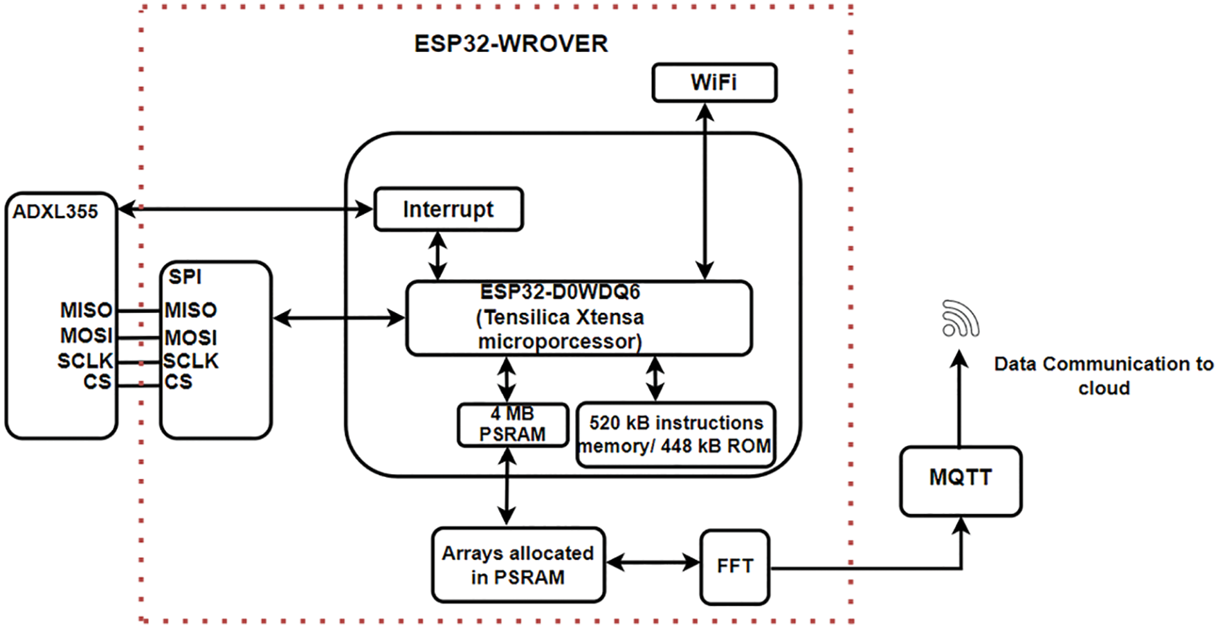
Figure 1: Architecture of our proposed IIoT node
3.2 Data Acquisition and Signal Processing
The data acquisition process is illustrated in Fig. 2. It outlines the steps for data acquisition and signal processing performed on the sensor node. The accelerometer’s sampling frequency is set at 2 kHz to comply with the Nyquist criteria and accurately detect faults and their harmonics in industrial motors, which normally operate at an RPM between 800 and 3600. To conserve CPU cycles and reduce the burden on the sensor’s core, data is collected every 60 min with a 4-min delay before being sent to the cloud using an interrupt. The interrupt is attached to the accelerometer’s data ready (DRDY) pin, and an Interrupt Service Routine (ISR) is called when the interrupt is attached, starting the data acquisition process as shown in Fig. 2.

Figure 2: Data acquisition and signal processing flowchart
Our sensor node performs three essential processes: data collection, signal processing, and transferring data to the cloud. These processes are time-consuming and require significant amounts of CPU cycles and memory resources of the MCU. Initially, we used two floating point arrays, each of length 4096 for both axes (x and z), which put a significant load on the MCU’s core and slowed down the program’s execution. To resolve this issue, we utilized the external 4 MB PSRAM of the MCU. This is a large amount of RAM for an MCU and can be used to store large amounts of information. The data collected from the accelerometer is stored in a dynamically allocated array in PSRAM for both axes. Two 4096-point arrays each of 16384 bytes are declared, using 0.016384 Megabytes of PSRAM. As previously discussed, after a complete set of samples is collected, the interrupt is detached, and the DRDY pin is no longer monitored for data.
Spectral analysis and FFT are used to analyze the vibration data collected from the motor in the frequency domain. However, its implementation was challenging due to the high memory requirements and computational intensity which put a burden on the MCU. To optimize FFT, we considered the balance between memory usage and step size. Ultimately the 4096-point FFT is chosen to reduce spectral leakage and accurately capture every frequency component. To implement FFT on the ESP32 core, Robin Scheibler’s FFT library was chosen, which is modified to work with the Arduino IDE and supports floating point data. We applied a split-radix algorithm for efficiency and used a hamming window to smooth the frequency spectrum before sending the processed data to the cloud.
Our sensor node collects and processes large amounts of data (240,000 readings) from two axes, and sends it to the cloud. In industrial settings, many similar nodes will be deployed and a lot of data will be generated, so we need a communication protocol that can handle this efficiently without high power demands or CPU load. Transferring data with the standard HTTP protocol will be inefficient since it requires high power, sufficient memory, and CPU load to support the TCP protocol and high-level HTTP RESTful APIs. We chose MQTT as it is a lightweight, low-bandwidth machine-to-machine communication protocol that allows IIoT devices to transfer data to a remote broker. MQTT is suitable for IIoT applications as it has a high throughput rate and allows sensor nodes to communicate and transmit data in resource-constrained environments with low bandwidth. With a small header size of 2 bytes, MQTT consumes very little power and allows for update rates in the 100-millisecond range even with external cloud brokers.
MQTT is a communication protocol that uses a publish-subscribe model. It consists of two main parts: clients and a message broker. Sensors, in this case, act as clients, and the message broker is typically a cloud server where data is transferred. In MQTT, data is published on a specific topic, which acts as a way of addressing the data. Once the data is published, any device that wants to receive it can subscribe to that topic. Fig. 3 explains the basic working of MQTT where the sensor node acts as the client, publishing a message (m1) to the topic “motor/vibrations” on the broker. The subscriber, in this case, would subscribe to this topic to receive the message.

Figure 3: Basic MQTT architecture
We have divided our communication process into two parts as shown in Fig. 4. In the first part, sensor node data is transferred to a local broker. We have chosen Mosquitto for this, as it is a lightweight and scalable MQTT broker. To ensure data backup, we have utilized the bridge feature where data from the local broker is transferred to the main broker. In the second part of the process, data from the Mosquitto broker is bridged to the main broker, EMQX. EMQX is also an MQTT broker that allows for efficient and reliable connections of massive IoT devices. It can handle millions of concurrent MQTT connections and can be used to send messages from a server to a client as well as connect to MQTT-compatible devices.

Figure 4: Communication process
Part 1 describes the process of sending data from the sensor node to Mosquitto. The sensor node and Mosquitto communicate using specific commands. First, the sensor node establishes a connection with Mosquitto by sending a CONNECT message, and Mosquitto responds with a CONNACK message. This connection remains open until the sensor node sends a disconnect message. Next, the sensor node begins publishing messages to Mosquitto by sending a PUBLISH command. The data being published includes the epoch time, FFT of the radial axis (x), and FFT of the axial axis (z). This data is sent to Mosquitto on the topic ‘motor/vibrations’. Mosquitto acknowledges receipt of the data based on the Quality of Service (QoS) level set for the sensor node. In our case, the QoS level is set to 1, which ensures that the message is delivered at least once to the receiver. The sensor node then waits for an acknowledgment message, PUBCACK, from Mosquitto, which confirms that the message has been published. Once this acknowledgment is received, the data is removed from the queue. If the acknowledgment is not received, the sensor node will keep resending the message.
Part 2 explains how data from the sensor node is transferred to a backup server using Mosquitto and EMQX. The data is crucial for making future decisions, so it’s important to create a backup copy of it on different servers. In case of a connection loss with Mosquitto, the system can still respond to changes if a backup is available. The two brokers are typically installed at different locations, allowing data to be accessible from various geographical locations. To accomplish this bridging process, we set up a bridge on Mosquitto and modified its default configuration. When configured as a bridge, Mosquitto acts as an MQTT client to EMQX and forwards messages to it. To establish a connection with EMQX, Mosquitto sends a CONNECT signal and waits for the acknowledgement ‘CONNACK’. Then, every incoming message on the topic ‘motor/vibrations’ in Mosquitto is forwarded to EMQX. EMQX acts as a normal broker and doesn’t require additional configuration.
Our cloud architecture, is shown in Fig. 5. It is highly flexible, low-cost, and customizable as per IIoT requirements. It consists of MQTT brokers (Mosquitto and EMQX), Apache Kafka as an event broker, TimescaleDB as a database, and lastly Grafana for the dashboard user interface (UI).

Figure 5: Cloud architecture
4 Experimental Setup and Results
A smart sensor node for the Industrial Internet of Things (IIoT) has been developed and tested in two different settings. The node was first installed and evaluated on two different motors using a motor testbed at a university lab. Following successful local testing, the node was then deployed at a rice factory on an induction motor for real-world use.
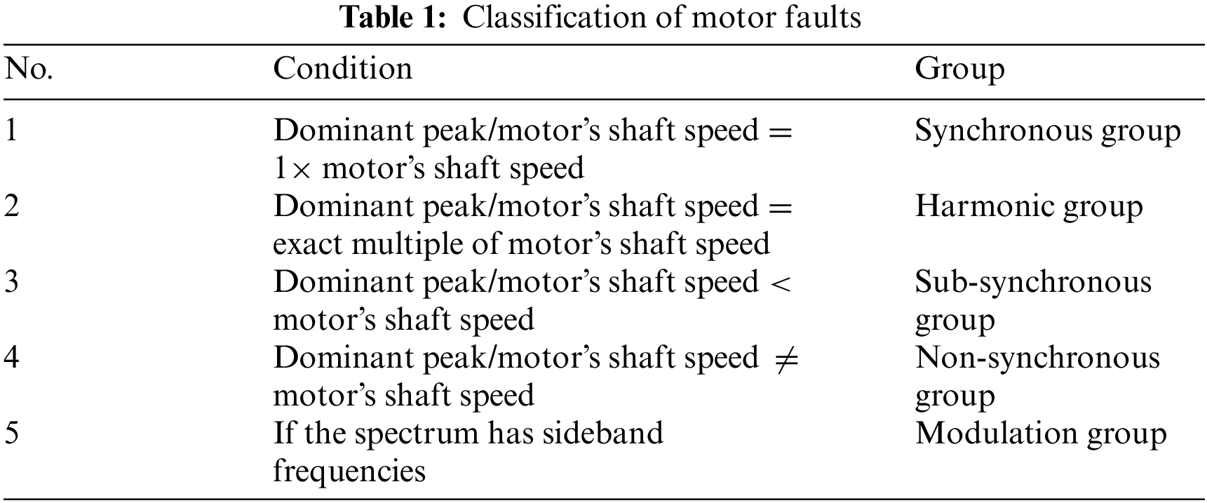
Different motor faults can be organized into groups based on specific patterns in the frequency spectrum, which allows us to quickly identify the type of fault. The frequency spectrum of a faulty motor typically includes dominant peaks, which are high in amplitude. There are five main groups of faults: the synchronous group, the harmonic group, the sub-harmonic/sub-synchronous group, the non-synchronous group, and the modulation/sidebands group. To determine the fault group, we first determine the motor’s shaft speed, which is the base RPM of the motor or 1 motor’s shaft speed. Then, we determine the dominant peak in the spectrum and use the following formula: Frequency Group = Dominant Peak/motor’s shaft speed. Table 1 shows the fault grouping according to this formula.
The motors used in both the testbed and the industry settings are directly coupled AC motors that drive loads that include rolling element bearings. As a result, the following faults are likely to occur: unbalance, eccentricity, bent shaft, inner and outer cocking faults, blade pass, rotor bar, bearing cage frequency, and inner and outer race faults in the rolling element bearings. These faults fall into various groupings as shown in Fig. 6.

Figure 6: Groupings of faults likely to occur in the studied motors
4.2 Scenario 1: Motor in Testbed Laboratory
In the first scenario, we set up an induction motor testbed at a university laboratory, as shown in Fig. 7. It includes a three-phase induction motor on which the sensor node is installed. The motor drives a 3-KW alternator, which converts the mechanical energy from the motor into electrical energy to supply the load. The motor and alternator are connected using a flange coupling. A Direct Online (DOL) starter is provided to start and stop the motor. An energy meter is used to measure electrical quantities such as current, voltage, and power. To mount the sensor node on the motor, we used a steel plate that was attached to the motor using screws. The sensor node was then mounted on the plate using magnets. In this scenario, we tested two three-phase induction motors, called M1 and M2. Both motors have the same specifications: a shaft speed of 25 Hz and a power output of 1.5 KW. M1 is new and healthy while M2 has been used for around 5000 h and has been induced with an inner race defect in the bearing.

Figure 7: Induction motor testbed
4.3 Scenario 2: Induction Motor in an Industrial Plant (Rice Factory)
In the second scenario, we selected a rice plant industry where the compressor is a crucial component, as shown in Fig. 8. The compressor is driven by an induction motor that has a shaft speed of 50 Hz and produces 38 KW. The compressor fills the air in an air tank and when the air pressure goes below 5.8 bar in the tank, it is filled again until 7 bar is reached. To analyze data in both situations, we collected data in two cycles. The first cycle involved data measurement and processing during the process of air compression. The second cycle involved data measurement during the air exhaust. In this scenario, the sensor node was mounted on a steel plate which was installed with the help of screws on the motor.

Figure 8: Compressor room (left), sensor node mounted on the motor at the industrial plant (right)
To analyze the spectrum in detail, we applied FFT (Fast Fourier Transform) in both the radial and axial directions on the vibration data of both motors. First, we installed M1 on the testbed and checked the working of the sensor node. We checked its shaft speed using a laser tachometer and it showed 25 Hz (1500 rpm) with some variations. These variations were caused by variations in the supply voltage, which could be seen on the energy analyzer installed on the motor testbed. Fig. 9 shows the frequency spectrum of M1 for both the radial and axial axes. Each of these graphs contains a peak at the motor’s shaft speed: 25.23 Hz on the radial axis and 25.26 Hz on the axial axis. There is no dominant peak found in the spectrum, indicating that M1 is in healthy condition. We also speculated that no fault was found in it. We observed a similar pattern even after several weeks of testing.

Figure 9: M1’s frequency spectrum for both radial and axial axes
In the next step of the process, we replaced the M1 with M2 and evaluated the node. Fig. 10 illustrates the frequency spectrum of M2 for both the radial and axial axes. In addition to the shaft speed, there are also prominent peaks in the spectrums. The radial axis has two dominant peaks at 302.43 and 805.51 Hz, while the axial axis only has one peak at 805.51 Hz. These peaks are not integer multiples of the shaft’s speed, which is 25.16 Hz. This indicates faults from the non-synchronous group. Additionally, the spectrum includes sideband frequency sets, as shown in red, which is a clear indication of faults from the modulation group. This suggests that M2 has faults from both the non-synchronous and modulation groups. As previously mentioned, M2 has a faulty bearing with an inner race fault, which falls under the non-synchronous and modulation group.

Figure 10: M2’s frequency spectrum for both radial and axial axes
We performed FFT on collected data in two cycles. The first cycle involved data measurement and processing during the process of air compression. The second cycle involved data measurement during the air exhaust. Fig. 11 shows the frequency spectrum for cycle 1 and Fig. 12 shows the frequency spectrum for cycle 2.

Figure 11: Cycle 1’s spectrum for both radial and axial axes

Figure 12: Cycle 2’s spectrum for both radial and axial axes
In cycle 1, as shown in Fig. 11, it can be seen that the shaft’s speed is around 49 Hz on both axes. There are also some dominant peaks present on both axes. The radial axis consists of a dominant peak at 268.03 Hz while the axial axis consists of a dominant peak at 98.78 Hz. Upon dividing them by the shaft’s speed, ratios indicate faults from the non-synchronous group. It can also be observed from the spectrum of both axes, that some peaks also consist of sideband frequency sets, as encircled in red, which indicate faults from the modulation group.
In cycle 2, as shown in Fig. 12, dominant peaks are at 269.45 and 448.8 Hz in the radial axis, while for the axial axis, there is only one dominant peak at 99.3 Hz. Upon dividing these dominant peaks by the shaft’s speed, ratios indicate faults from the non-synchronous group. It can also be seen from the spectrum that some peaks in both axes also consist of sideband frequency sets which indicate faults from the modulation group. It was verified by the industry experts that this motor needed replacement of its current bearing since it had incurred some defect. The bearing faults come under both the non-synchronous and modulation group and this indicates the correct working of our sensor node.
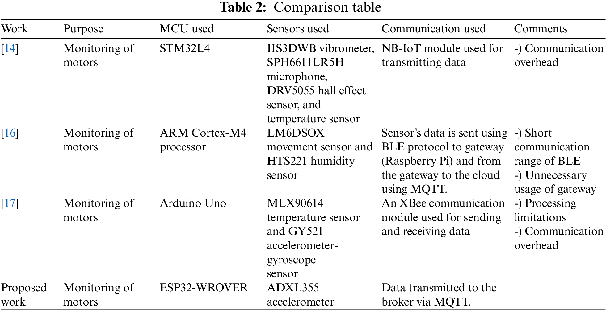
Table 2 compares the proposed sensor node to other nodes designed for the same applications. Some solutions, such as those outlined in references [14] and [17], utilize hardware modules for data communication. However, the solution in [16] involves mobile operators and incurs hardware overhead, while the solution in [17] requires the same module at the receiver end and uses an Arduino Uno which has limited processing capabilities for signal processing. Additionally, the solution in [16] uses a Raspberry Pi as a gateway, which is costly and relies on the BLE protocol for data transmission, which has a limited communication range. In contrast, the proposed sensor node has no hardware overhead, sufficient computing capabilities, and the capability to wirelessly transfer large data using a lightweight protocol.
In this study, we developed an IIoT-based smart sensor node with a focus on the need for predictive maintenance. This node has an efficient controlling unit capable of handling large amounts of data and performing onboard signal processing. Additionally, a lightweight wireless communication protocol was used for transferring data to the cloud without the need for an additional WiFi module. The node’s high sampling rate accelerometer makes it particularly useful for monitoring the health of a wide range of industrial motors. Field testing was conducted to ensure its reliability and validate the effectiveness of the proposed sensor node in industrial settings. There is potential for further improvements in the future by incorporating controllers with more advanced digital signal processing capabilities and higher memory capacity, which would enable the implementation of higher point FFT.
Funding Statement: This paper is supported by the NCAIRF 079 project fund. The project is funded by National Center of Artificial Intelligence.
Conflicts of Interest: The authors declare that they have no conflicts of interest to report regarding the present study.
References
1. M. S. Moiz, S. Shamim, M. Abdullah, H. Khan, I. Hussain et al., “Health monitoring of three-phase induction motor using current and vibration signature analysis,” in 2019 Int. Conf. on Robotics and Automation in Industry (ICRAI), Rawalpindi, Pakistan, pp. 1–4, 2019. [Google Scholar]
2. M. Kostic, “Effects of voltage quality on induction motors’ efficient energy usage,” in Induction Motors—Modelling and Control. London, United Kingdom: IntechOpen, 2012. [Online]. Available at: https://www.intechopen.com/chapters/40947 [Google Scholar]
3. P. Zhang, Y. Du, T. G. Habetler and B. Lu, “A survey of condition monitoring and protection methods for medium-voltage induction motors,” IEEE Transactions on Industry Applications, vol. 47, no. 1, pp. 34–46, 2011. [Google Scholar]
4. F. Z. Dekhandji, S. E. Halledj and O. Zaboub, “Predictive maintenance applied to three-phase induction motors,” Algerian Journal of Signals and Systems, vol. 4, no. 2, pp. 71–88, 2019. [Google Scholar]
5. P. Sethi and S. R. Sarangi, “Internet of Things: Architectures, protocols, and applications,” Journal of Electrical and Computer Engineering, vol. 2017, no. 1, pp. 1–25, 2017. [Google Scholar]
6. R. Joost and R. Salomon, “Advantages of FPGA-based multiprocessor systems in industrial applications,” in 31st Annual Conf. of IEEE Industrial Electronics Society, 2005. IECON 2005, Raleigh, NC, USA, pp. 1–6, 2005. [Google Scholar]
7. J. Medina-García, T. Sánchez-Rodríguez, J. A. G. Galán, A. Delgado, F. Gómez-Bravo et al., “A wireless sensor system for real-time monitoring and fault detection of motor arrays,” Sensors, vol. 17, no. 3, pp. 469, 2017. [Google Scholar]
8. X. Zhang, K. P. Rane, I. Kakaravada and M. Shabaz, “Research on vibration monitoring and fault diagnosis of rotating machinery based on internet of things technology,” Nonlinear Engineering, vol. 10, no. 1, pp. 245–254, 2021. [Google Scholar]
9. Q. Huang, B. Tang and L. Deng, “Development of high synchronous acquisition accuracy wireless sensor network for machine vibration monitoring,” Measurement, vol. 66, pp. 35–44, 2015. [Google Scholar]
10. B. Bengherbia, R. Kara, A. Toubal, M. O. Zmirli, S. Chadli et al., “FPGA implementation of a wireless sensor node with a built-in ADALINE neural network coprocessor for vibration analysis and fault diagnosis in machine condition monitoring,” Measurement, vol. 163, pp. 107960, 2020. [Google Scholar]
11. J. Aponte-Luis, J. Gómez-Galán, F. Gómez-Bravo, M. Sánchez-Raya, J. Alcina-Espigado et al., “An efficient wireless sensor network for industrial monitoring and control,” Sensors, vol. 18, no. 2, pp. 182, 2018. [Google Scholar] [PubMed]
12. A. Shahraki, A. Taherkordi, Ø. Haugen and F. Eliassen, “Clustering objectives in wireless sensor networks: A survey and research direction analysis,” Computer Networks, vol. 180, no. 3, pp. 107376, 2020. [Google Scholar]
13. A. Zeb, A. K. M. M. Islam, M. Zareei, I. Al Mamoon, N. Mansoor et al., “Clustering analysis in wireless sensor networks: The ambit of performance metrics and schemes taxonomy,” International Journal of Distributed Sensor Networks, vol. 12, no. 7, pp. 4979142, 2016. [Google Scholar]
14. T. Polonelli, A. Bentivogli, G. Comai and M. Magno, “Self-sustainable IoT wireless sensor node for predictive maintenance on electric motors,” in 2022 IEEE Sensors Applications Symp. (SAS), Sundsvall, Sweden, pp. 1–6, 2022. [Google Scholar]
15. L. Magadán, F. J. Suárez, J. C. Granda and D. F. García, “Low-cost real-time monitoring of electric motors for the industry 4.0,” Procedia Manufacturing, vol. 42, pp. 393–398, 2020. [Google Scholar]
16. L. Magadán, F. J. Suárez, J. C. Granda and D. F. García, “Low-cost industrial IoT system for wireless monitoring of electric motors condition,” Mobile Networks and Applications, 2022. https://doi.org/10.1007/s11036-022-02017-2 [Google Scholar] [CrossRef]
17. K. Mykoniatis, “A real-time condition monitoring and maintenance management system for low voltage industrial motors using internet-of-things,” Procedia Manufacturing, vol. 42, pp. 450–456, 2020. [Google Scholar]
18. B. Bengherbia, M. Ould Zmirli, A. Toubal and A. Guessoum, “FPGA-based wireless sensor nodes for vibration monitoring system and fault diagnosis,” Measurement, vol. 101, pp. 81–92, 2017. [Google Scholar]
19. F. Di Nuzzo, D. Brunelli, T. Polonelli and L. Benini, “Structural health monitoring system with narrowband IoT and MEMS sensors,” IEEE Sensors Journal, vol. 21, no. 14, pp. 16371–16380, 2021. [Google Scholar]
20. S. K. Bhoi, S. K. Panda, K. K. Jena, K. S. Sahoo, N. Z. Jhanji et al., “IoT-EMS: An internet of things based environment monitoring system in volunteer computing environment,” Intelligent Automation & Soft Computing, vol. 32, no. 3, pp. 1493–1507, 2022. [Google Scholar]
21. Q. Meng and S. Zhu, “Developing IoT sensing system for construction-induced vibration monitoring and impact assessment,” Sensors, vol. 20, no. 21, pp. 6120, 2020. [Google Scholar] [PubMed]
22. O. Rubes, J. Chalupa, F. Ksica and Z. Hadas, “Development and experimental validation of self-powered wireless vibration sensor node using vibration energy harvester,” Mechanical Systems and Signal Processing, vol. 160, no. 9, pp. 107890, 2021. [Google Scholar]
23. A. A. Jaber and R. Bicker, “Design of a wireless sensor node for vibration monitoring of industrial machinery,” IJECE, vol. 6, no. 2, pp. 639, 2016. [Google Scholar]
Cite This Article
 Copyright © 2023 The Author(s). Published by Tech Science Press.
This work is licensed under a Creative Commons Attribution 4.0 International License , which permits unrestricted use, distribution, and reproduction in any medium, provided the original work is properly cited.
 Downloads
 Citation Tools