
 Submit a Paper
 Propose a Special lssue
 Open Access
ARTICLE
Study of Local Structural Changes on Air Cooling at the End of Rotor Windings for Variable Speed Pumped Storage Generator-Motor
1 University of Chinese Academy of Sciences, Beijing, 100049, China
2 Institute of Electrical Engineering of Chinese Academy of Sciences, Beijing, 100049, China
3 Dongfang Electric Machinery Co., Ltd., Deyang, 618000, China
* Corresponding Author: Zhe Hou. Email:
Energy Engineering 2022, 119(6), 2243-2254. https://doi.org/10.32604/ee.2022.021322
Received 07 January 2022; Accepted 08 April 2022; Issue published 14 September 2022
 View Full Text
 Download PDF
Abstract
The shrink fit retaining ring is currently the easiest to install and the most widely used end fixed for structure AC excitation variable speed generator-motor rotor end windings. However, the current research on the effect of high strength sealing on the ventilation and heat dissipation performance of the end is not enough. In this paper, based on the actual structural parameters and periodic symmetry simplification, the three-dimensional coupled calculation model of fluid field and temperature field is established. After solving the fluid and thermal equations, the influence of the length of rotor support block, the height of rotor support block, and the number of rotor support block on the fluid flow and temperature distribution in the rotor end region of generator-motor is studied using the finite volume method. The rheological characteristics of the air in the rotor domain, such as velocity and inter-winding flow, are analyzed. The law of temperature variation with local structure in the computational domain is studied. The variation law of cooling medium performance inside the large variable speed power generator motor is revealed.Keywords
With the large-scale grid connection of random intermittent clean energy sources such as wind and solar power, the number of power devices operating at night on a regular basis has increased [1,2]. Variable-speed generator motors have millimeter-scale corresponding speed and wide power regulation range, which can maintain the stability of the grid [3].
The rotor core of variable speed power generator motor is heavy than the fixed-speed power generator motor. The rotor winding end needs to be fixed by shrink fit retaining ring to withstand the rotating centrifugal force. However, the shrink fit retaining ring fixing method has a high confinement and high excitation current of the rotor winding. A reasonable cooling method must be used to remove the heat from the winding ends to enable the motor to operate stably for a long time. At present, there is not enough theoretical research on the characteristics of the fluid-temperature field distribution at the rotor winding end of variable speed power generator-motor. Therefore, it is necessary to analyze the fluid rheological characteristics of the rotor winding ends effectively. It is an important reference for the improvement of the cooling effect at the rotor winding end and the design of higher capacity and higher speed variable speed generator-motor.
At present, domestic and foreign experts and scholars have analyzed and compared the ventilation and cooling methods and end fixing structures of the variable speed power generation motor machine [4–6]. Many numerical calculations of the fluid and temperature fields inside the motor and the corresponding coupling fields have also been performed using the finite volume method for other types of motors [7–12]. The basis for the calculation of the physical fields inside the motor has been laid. However, there are fewer research results on the fluid rheological characteristics and temperature rise distribution inside variable speed generator-motor. In particular, the distribution characteristics of the rotor winding ends after using different fixed structures are less studied. At present, there is no AC-excited variable speed generating motor in operation in China. Numerical simulation with the help of commercial software can study the distribution pattern of rotor winding ends more quickly and effectively. Therefore, a numerical solution model is used to study the fluid flow characteristics at the end of the rotor winding of the variable speed generator-motor. The effect of local structural changes on the distribution pattern of the relevant parameters is also analyzed. It has certain theoretical guidance significance.
In this paper, based on the actual structural parameters and periodic symmetry simplification, the three-dimensional coupled calculation model of fluid field and temperature field is established. After solving the fluid and thermal equations, the influence of the length of rotor support block, the height of rotor support block, and the number of rotor support block on the fluid flow and temperature distribution in the rotor end region of generator-motor is studied using the finite volume method.
2 Ventilation Structure and Establishment of Mathematical Model
2.1 Basic Motor Data and Ventilation Structure
In this paper, a 600 MW variable speed generator motor is studied as an example. The basic motor data are shown in Table 1.
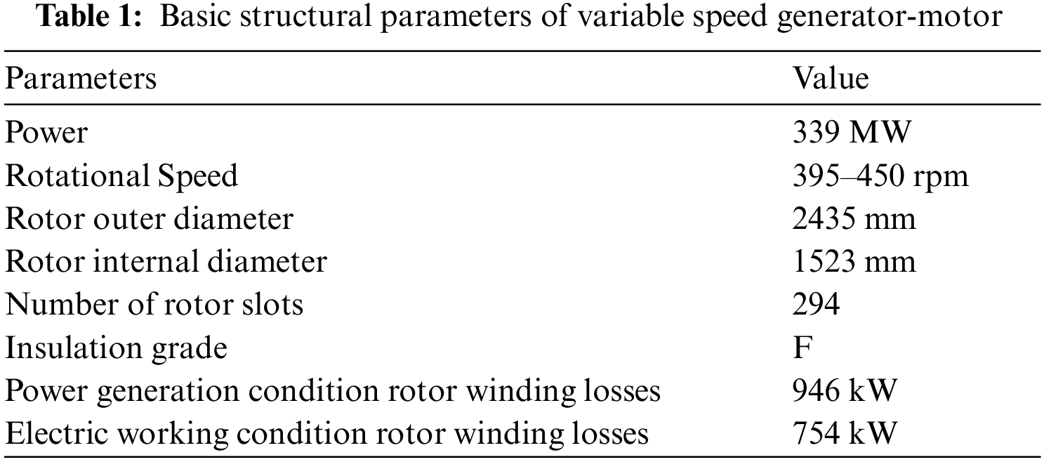
The air-cooling path of end windings is shown in Fig. 1. The end support blocks are placed in a circumferential direction which act as radial fans depending on the rotor rotation. The air blowing from the condenser reaches the end of the winding and enters the runner. A portion of the air passes through the air aluminum block between the windings for indirect cooling of the windings. Another small portion of the radial air flows out of a small gap at the lower end of the outer ring.

Figure 1: Simplified air-cooling structure of rotor windings end
According to the theory of fluid mechanics, this paper compares the calculation results of three common turbulence models and finds that there is not much difference. Based on the characteristics and advantages of SST
where
Combine the material properties of the motor and the basic principles of heat and mass transfer. Synthetic equation of steady-state temperature field:
where:
The law of conservation of energy is the basic law that must be satisfied by the flow system containing the heat exchange process. Fluid energy conservation equation:
where:
2.3 Establishment of Physical Model
The end physical model of solved region is shown in Fig. 2. The fluid regions include the rotating air area and the static air area. The solid regions which are simplified by the actual structure include core and ring, windings, equivalent insulation layer, hollow aluminum block, support block. The one layer of insulation contains the main insulation and the insulating paint of the winding which is set by the formula [17]. The lower windings are numbered in counterclockwise direction. The upper windings are numbered in clockwise direction.

Figure 2: The end physical model of solved region
2.3.2 Setting of Boundary Conditions
Boundary conditions for the coupled solution of the fluid and temperature fields:
1. The motor is running in generator condition. The rotation speed is set to 400 rpm.
2. The air temperature at the inlet of the support block is 60°C.
3. The entrance and exit boundaries are all at standard atmospheric pressure. Both inlet and outlet are pressure boundary conditions.
4. The heat source density of the body at the end of the rotor windings loss calculation is used as the heat source.
5. Both the solid contact surface and the fluid-solid contact surface in the computational domain are coupled surfaces.
For the subdivision map of solved region, the Fluent meshing is used to divide the mixed high-quality mesh of prismatic boundary layer mesh and hexahedral core body mesh. The surface mesh is generated by global size constraint, local encryption, surface diagnosis to improve the quality of the surface mesh, shared topology, automatic body mesh generation, mesh node movement and other settings. The nodes of the fluid-solid intersection ensure consistency. Periodic boundary conditions on both sides are maintained. The generated hexahedral hybrid mesh can ensure higher mesh quality and higher computational accuracy with smaller number of meshes. The subdivision map of solved region is shown in Fig. 3.

Figure 3: Subdivision map of solved region
3 Analyze and Discuss the Three-Dimensional Fluid Field and Temperature Field
3.1 Influence of the Number of Support Block on Fluid and Temperature Field
The support blocks are located at the inlet for rotor windings ventilation which are used to provide air intake channels. The model of the original actual project is 49 support blocks in the circumferential direction. In this part, the effects of doubling the number of support blocks on the fluid field and temperature field at the end of windings is studied.
In order to analyze the influence of the number of support blocks on the fluid, the bottom section

Figure 4: Simulation of velocity distribution diagram
In order to more clearly analyze the influence of the number of support blocks on the temperature field, the temperature distribution at the position of No. 4–10 windings at the upper and lower layers is extracted, as shown in Fig. 5. When the number of support blocks changes, the temperature of the selected upper winding decreases and the temperature of the lower winding increases. Overall, the temperature difference between the upper and lower windings decreases. The doubling number changes the distribution of cooling air. The temperature of the lower winding increases but the temperature of the upper winding decreases. The distribution of each flow path is more uniform. The temperature peaks and differences between the upper and lower windings are reduced.

Figure 5: Comparison of sampling line temperature diagram at two quantities
3.2 Influence of Support Block Length on Fluid Field and Temperature Field
In the basic model, the length of the support block is the same radius as the iron core. In order to study the influence of the length change on the ventilation and heat dissipation of the winding, the support blocks with four lengths are selected for simulation calculation. The support block length mark is listed in Table 2.
The mass flow and velocity values of the inlet at different lengths are extracted as shown in Fig. 6. In general, when the length of the support block is the same as the radius of the iron core, the mass flow and flow rate at the inlet are the largest. This is because with the decrease of the length of the support block, more inlet cooling air can enter from the side, which will affect the value of the inlet surface.

Figure 6: Effect of length on inlet flow and velocity
In order to analyze the influence of the length of the support block on the fluid distribution, the middle section

Figure 7: Effect of length on the velocity and mass flow of the inter-winding section
To further analyze the effect of the change in length of the front end of the support block on the temperature field. The temperature distribution of the sampled lines at the same locations on the surface of the upper and lower 4–10 windings is likewise extracted. This is shown in Fig. 8. It can be seen that: when the length of the support block is varied within the range, the overall temperature of the winding does not vary much, and the difference is around 1 K. When the length is CD1, the temperature of both upper and lower windings is the lowest, which is consistent with the winding runner section flow law. When the length is other, the difference of winding temperature is not significant. Consistent with the distribution characteristics of the flow rate of the winding runner cross-section, the distribution pattern is not very obvious. Therefore, taking the temperature value of the sampling line on the winding surface as an example, the ventilation and heat dissipation capacity of the rotor winding end is optimal when the length of the front end of the support block is kept at CD1. The length is the same as the inner diameter of the core platen.

Figure 8: Influence of length change on No. 4–10 windings temperature diagram
3.3 Influence of Support Block Height on Fluid Field and Temperature Field
The height of the support block determines the size of the inlet area, which has an important impact on the ventilation and heat dissipation of the end windings. However, with the increase of the height, the overlapping area between the inner ring and the inlet is larger, so there will be greater reflux at the inlet, which needs to be further studied in detail. Therefore, five support block models GD1–GD5 with different heights are selected to study the effect of height on ventilation and heat dissipation at the end of windings. The support block height mark is listed in Table 3.
When the support block height increases, the mass flow at the inlet is directly proportional to the height, and the average velocity at the inlet is inversely proportional to the height. When the height GD4 is 190 mm, the mass flow at the inlet is the maximum and the average speed is the minimum. When the height is GD5, the mass flow rate should increase in principle when the cross-sectional area and the average flow rate of the cross-section increase. But the actual surface mass flow rate does not increase but slightly decreases. The reason is that the height increases. The mass flow rate of the inlet air that produces a return flow after reaching the surface of the inner ring increases. The effect of height change on inlet flow and velocity is shown in Fig. 9.

Figure 9: The effect of height changes on inlet flow and velocity
In order to further analyze the influence of the height of the support block on the fluid field, the middle section

Figure 10: Effect of height on the velocity and mass flow of the inter-winding section
When the height of the support block changes from 130 to 210 mm, the variation trend of cross-section velocity and mass flow between windings is relatively regular. When the height is GD2, the flow rate and flow rate are the smallest, and the cooling effect should be poor. With the change of height, the air velocity and mass flow increase, but the difference between them is not great. When the inlet height is GD5, the flow velocity and flow of its section do not obviously reach the maximum value, because the inlet will produce greater reflux, which will affect the ventilation and heat dissipation of the windings. For the lower windings, the pattern of the effect of height on the flow and flow rate in the interwinding section is not obvious. For the upper windings, GD4 have greater mass flow and air velocities.
The effect of the change in height of the front end of the support block on the temperature field is further analyzed. The temperature of the sampled lines at the same position on the surface of the upper and lower 4–10 windings is also extracted. Based on the five heights of GD1–GD5, the temperature distribution of the sampled lines on the surface of the upper and lower 4–10 windings are compared. As shown in Fig. 11. For the upper layer 4–10 windings, the temperature difference is not large, around 1 K. When the height is GD4, the surface temperature is relatively low. But the temperature difference with other heights is not large. For the lower layer 4–10 windings, the temperature of the winding under height GD2 is relatively large, and the temperature of the winding under height GD4 is relatively small. But the temperature difference with the other heights under the other heights is not large.

Figure 11: Influence of length change on No. 4–10 windings temperature diagram
In this paper, the physical model with the retaining ring fixed pattern is established based on the actual motor structural parameters of a power station. The end periodic three-dimensional coupling transfer model is set with some assumptions. The fluid-temperature distribution characteristics at the end of the winding is calculated by the finite volume numerical simulation method. Based on the simulation results, the effects of the number, length and height of inlet support blocks on air-cooling end windings are studied. The following conclusions are obtained:
1. When the number of support blocks is varied, the bottom runner is divided into two identical runners. Increasing the number of support blocks allows for a more uniform distribution of air flow in each channel. The maximum temperature value in the calculation domain decreases after increasing the quantity. The temperature of the upper winding sampling line is reduced and the lower windings is slightly increased.
2. When the support block length is varied, for the fluid field, the peak flow velocity decreases as the length decreases. The mass flow rate and air velocity values at the inlet decrease. The air velocity and mass flow rate of the interwinding flow path cross section decrease. For the temperature field, the temperature of the winding sampling line increases as the length decreases. In the range of height variations in this paper, CD1 corresponds to the length of the support block for best ventilation and heat dissipation performance in the range of variations in this paper.
3. When the support block height is varied. For the fluid field, the mass flow rate and flow velocity values at the inlet increase and then decrease as the height increases. When the height is GD4, the flow velocity and mass flow rate of the flow channel cross section between the windings are maximum. For the temperature field, there is little difference in the temperature of the winding sampling line as the height increases. In the range of height variations in this paper, overall GD4 corresponds to the lowest temperature for the upper and lower windings in the range of variations in this paper.
Funding Statement: This research was funded by Dongfang Electric Machinery Co., Ltd.
Conflicts of Interest: The authors declare that they have no conflicts of interest to report regarding the present study.
References
1. An, Z. P., Wu, J. H., Liao, W. L., Tong, J. W., Chen, C. C. et al. (2018). Application of AC excitation variable speed pumped storage technology and its prospect. Pumped Storage Power Plant Engineering Construction Anthology, vol. 5. Changsha, Hunan, China. [Google Scholar]
2. Joseph, A., Chelliah, T. R. (2018). A review of power electronic converters for variable speed pumped storage plants: Configurations, operational challenges, and future scopes. IEEE Journal of Emerging and Selected Topics in Power Electronics, 6(1), 103–119. DOI 10.1109/JESTPE.2017.2707397. [Google Scholar] [CrossRef]
3. He, R. (2021). Analysis and comparison on power characteristics of fixed-speed and variable-speed pumped storage unit. 2021 IEEE International Conference on Power, Intelligent Computing and Systems (ICPICS), pp. 539–543. Shenyang, China. [Google Scholar]
4. Liu, J. J., Zheng, X. K., Qian, C. Y., Luo, L., Du, F. M. (2014). Design of variable speed pumped storage power generation motor. Pumped Storage Power Plant Engineering Construction Anthology, vol. 6. Deyang, Sichuan, China. [Google Scholar]
5. Luo, L. (2021). Research on the design of variable speed pumped storage power motor. Hydropower and Pumped Storage, 7(s4), 43–50. [Google Scholar]
6. He, R. F., Wang, F., Zhang, H. (2020). Technical route and selection of key parameters for seawater variable speed pumped storage units. Water Resources and Hydropower Technology, 184–189. [Google Scholar]
7. La, R. A., Zou, T. J., Moslemin, M., Gerada, D., Gerada, C. et al. (2021). Thermal modelling of a liquid cooled traction machine with 8-layer hairpin windings. IECON 2021--47th Annual Conference of the IEEE Industrial Electronics Society, pp. 1–6. Toronto, ON, Canada. [Google Scholar]
8. Korovkin, N. V., Verkhovtsev, D., Gulay, S., Mauabtcev, M., Liamin, A. (2021). Analysis of the temperature non-uniformity of the rotor winding of a powerful air-cooled turbogenerator. 3rd International Youth Conference on Radio Electronics, Electrical and Power Engineering (REEPE), pp. 1–5. Moscow, Russia. [Google Scholar]
9. Boscaglia, L., Bonsanto, F., Boglietti, A., Nategh, S., Scema, C. (2019). Conjugate heat transfer and CFD modeling of self-ventilated traction motors. 2019 IEEE Energy Conversion Congress and Exposition (ECCE), pp. 3103–3109. Baltimore, MD, USA. [Google Scholar]
10. Rehman, Z., Seong, K. (2018). Three-D numerical thermal analysis of electric motor with cooling jacket. Energies, 11(1), 92. DOI 10.3390/en11010092. [Google Scholar] [CrossRef]
11. Meng, D. W., Lu, Y. F., Xu, Y. M. (2011). Analysis of fluid field and temperature field of MW wind turbine based on fluent. 2011 Fourth International Conference on Intelligent Computation Technology and Automation, vol. 1, pp. 59–62. [Google Scholar]
12. Wang, Y., Ding, S. Y. (2020). Analysis of fluid field in doubly-fed hydro-generator. 2020 12th IEEE PES Asia-Pacific Power and Energy Engineering Conference (APPEEC), pp. 1–5. Nanjing, China. [Google Scholar]
13. Wang, Z. (2020). Parameter correction of SST k-ω turbulence model driven by obtuse body wind pressure data. Harbin, China: Harbin Institute of Technology. [Google Scholar]
14. Zhou, Y., Qian, W. Q., Deng, Y. Q., Ma, M. S. (2010). Preliminary analysis of parameter effects in the k-ω SST two-equation turbulence model. Journal of Aerodynamics, 28(2), 213–217. [Google Scholar]
15. Ren, Y., Liu, H. L., Shu, M. H., Wu, X. F., Wu, D. H. (2012). Improvement of SST k-ω turbulence model considering the effects of rotation and curvature. Journal of Agricultural Machinery, 43(11), 123–128. [Google Scholar]
16. Ding, S. Y., Ge, Y. Z., Xu, D. G., Miao, L. J., Yu, X. L. et al. (2012). Analysis of the fluid field in a 1.5 MW doubly-fed wind turbine. Chinese Journal of Electrical Engineering, 32(21), 93–98. [Google Scholar]
17. Fu, M., Yan, H., Yin, Z. Y., Wang, W. L., Ma, C. X. (2019). Coupling calculation of 3D whole domain steady flow and temperature field for underwater oil-filled brushless DC motors. 2019 2nd International Conference on Electrical Machines and Systems (ICEMS), pp. 1–6. Harbin, China. [Google Scholar]
Cite This Article
 Copyright © 2022 The Author(s). Published by Tech Science Press.
This work is licensed under a Creative Commons Attribution 4.0 International License , which permits unrestricted use, distribution, and reproduction in any medium, provided the original work is properly cited.
 Downloads
 Citation Tools