
 Submit a Paper
 Propose a Special lssue
 Open Access
ARTICLE
Research on VSG Frequency Characteristics and Energy Storage Device Capacity and Charge-Discharge Characteristics Based on Feedforward Branch
1 School of Automation & Electrical Engineering, Lanzhou Jiaotong University, Lanzhou, China
2 Qinghai Nationalities University, Xining, China
* Corresponding Author: Shanyan Ping. Email:
Energy Engineering 2022, 119(6), 2347-2367. https://doi.org/10.32604/ee.2022.021693
Received 28 January 2022; Accepted 25 April 2022; Issue published 14 September 2022
 View Full Text
 Download PDF
Abstract
Renewable energy is connected to the grid through the inverter, which in turn reduces the inertia and stability of the power grid itself. The traditional grid-connected inverter does not have the function of voltage regulation and frequency regulation and can therefore no longer adapt to the new development. The virtual synchronous generator (VSG) has the function of voltage regulation and frequency regulation, which has more prominent advantages than traditional inverters. Based on the principle of VSG, the relationship between the frequency characteristics and the energy storage capacity of the feedforward branch-based virtual synchronous machine (FVSG) is derived when the input power and grid frequency change. Reveal the relationship between the virtual inertia coefficient, damping coefficient, and frequency characteristics of VSG and energy storage capacity. An energy storage configuration method that meets the requirements of frequency variation characteristics is proposed. A mathematical model is established, and the Matlab/Simulink simulation software is used for modeling. The simulation results verify the relationship between the inertia coefficient, damping coefficient, and energy storage demand of the FVSG.Keywords
Nomenclature
| Ts | Mechanical torque |
| Te | Electromagnetic torque |
| D | Damping coefficient |
| J | Moment of inertia |
| Pin | Input power |
| Pout | Output power |
| Pin0 | Rated input power |
| Pout0 | Rated output power |
| Pes | The charging and discharging power of the energy storage device |
| Mechanical angular frequency | |
| Rated angular frequency | |
| Grid frequency | |
| Difference between output corner frequency and rated corner frequency | |
| Difference between actual input power and rated input power | |
| Difference between actual output power and rated output power | |
| ua, ub, uc | Output three-phase voltage |
| uga, ugb, ugc | Three-phase voltage of the grid |
| Udc | DC bus voltage |
| U | Valid values for ua, ub and uc |
| Ug | Valid values for uga, uga and ugc |
| U0 | Ratings for ua, ub and uc |
| Rated power angle | |
| H | Feedforward gain |
| Ees | Charge and discharge energy of energy storage device |
| K | Synchronization factor |
With the rapid development and innovation of what is often called “new energy,” represented by photovoltaic and wind power, these resources have been more widely used and worked into power grids over recent years [1–3]. However, due to the constraints of output characteristics, new energy power sources are generally connected to the grid through power electronic interface devices. Therefore, this new energy type is classified as inverter-based power [4,5]. At present, these new energy sources are mainly connected to the grid through inverters because inverters do not have the inertia and damping characteristics of generators, and virtual synchronous generators (VSG) can simulate the inertia and damping inertia of synchronous generators, once VSG was proposed, it was widely studied and applied [6,7]. VSG has no rotor and mainly simulates the moment of inertia and damping generated by the rotor through control algorithms. The VSG realizes grid connection by affecting the generator’s actual output characteristics so that the grid’s stability is consistent with the traditional generator, which is beneficial to the operation and management of the grid. Inertia and damping are mainly determined by the control algorithm of the inverter and the parameters of the energy storage device. There are many kinds of research on the control algorithm and stability of the VSG, and less research on the relationship between the VSG parameters and the energy storage devices [8–10].
Geng et al. [11] summarized the principal models of various VSGs. Zhang et al. [12] proposed a power quality control strategy based on a small-signal virtual synchronous machine microgrid. Chen et al. [13] proposed an improved control strategy for the converter at the receiving end of the VSG. Daili et al. [14] proposed a VSG frequency control strategy based on digital frequency protection to improve frequency stability and maintain the dynamic safety of inertial systems. Yan et al. [15] proposed an inertial fuzzy control that allows dynamic adjustment of inertia. Yan et al. [16] operated the PV system at sub-optimal operating points and performs a support strategy that simulates inertia and primary FM characteristics. Gao et al. [17] combined PV and energy storage to achieve both virtual inertia and independent operation. Lu et al. [18–23] analyzed the improved VSG control algorithm and its implementation; Song et al. [24–26] analyzed the strategy of virtual inertia allocation and regulation of multi-VSG systems. The parameters of the VSG require not only the setting of the control algorithm but also the support of the energy storage capacity. Most of the aforementioned previous literature does not examine the impact of energy storage. Xing et al. [27] studied the energy storage configuration methods on different occasions to find the optimal energy storage configuration scheme. Still, it did not explain the energy storage requirements in terms of inertia and damping.
Meng et al. [28] have studied the energy storage model and the power control method of charging and discharging for the photovoltaic application of VSG but have not deduced the capacity requirements of VSG inertia and damping and energy storage. The Gao et al. [17] studied the optimal configuration structure of the energy storage system. Still, it has not yet calculated the relationship between the inertia and damping of the VSG and the capacity of the energy storage device.
This paper first proposes a feed-forward branch-based virtual synchronous generator (FVSG) system for the optimisation of the robustness of conventional VSGs. The relationship between the frequency characteristics and parameters of the FVSG, the inertia and damping coefficients, and the capacity and charging/discharging characteristics of the energy storage unit are then all analysed in the presence of input power disturbances and grid frequency variations. The corresponding relationships are derived to give the optimal configuration parameters of the energy storage unit. The results of the study can be used for the design of FVSG parameters and the capacity configuration of energy storage devices.
2 Establishment of FVSG Mathematical Model
2.1 Mathematical Model of Traditional VSG
The synchronous generator has a rotor and has a particular inertia, so the system’s frequency will not change abruptly in a short time. The VSG introduces virtual inertia moment control in the control algorithm of the inverter to simulate the rotor inertia of the synchronous generator. The mechanical rotation equation of the synchronous generator is shown in equation [27,29,30]
where, Ts is the mechanical torque input by the generator; Te is the electromagnetic torque of the generator; D is the damping coefficient of the generator; J is the moment of inertia of the generator;
The mechanical power of the synchronous generator is defined as equation
The electromagnetic power of the synchronous generator is defined as equation
The equation can be obtained from equation to
The VSG simulates the rotor motion equation of the synchronous generator mainly by controlling the control algorithm of the inverter. It can simulate the moment of inertia and damping characteristics of the synchronous generator and realize the stability and droop characteristics of the output voltage and frequency of the virtual synchronous generator. The schematic diagram of the virtual synchronization machine is shown in Fig. 1.
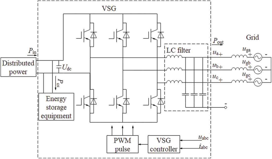
Figure 1: Diagram of VSG system
In the figure: Pout is the output power; Pin is the input power; Pes is the charging and discharging power of the energy storage device; ua, ub and uc are the output three-phase phase voltages; uga, ugb, and ugc are the three-phase phase voltages of the grid; Udc is the input DC bus voltage.
When the number of pole pairs of the VSG is considered to be 1, the angular frequency of the induced electromotive force is the same as the mechanical angular frequency of the rotor rotating, and the equation can be obtained from the equation
where, J is the moment of inertia of the VSG; D is the damping coefficient of the VSG.
Use Pin0 to represent the rated input power of the VSG, and Pout0 to represent the rated output power of the VSG.
Let
Equations can be obtained when the VSG operates under the rated steady-state operating conditions.
Equation can be obtained from equations to
The active output power of the generator can be expressed as equation
where, U represents the effective value of ua, ub and uc; Ug represents the effective value of uga, ugb and ugc. Let
Since
When U and Ug are constant, because of
Let
The variation of the VSG angle of attack can be expressed as equation
where,
Equations are the small-signal time-domain mathematical models of the VSG. Laplace transform can be used to obtain the small-signal frequency-domain mathematical model of VSG, as shown in equations to
According to equations to, the transfer function block diagram of VSG can be obtained as shown in Fig. 2.
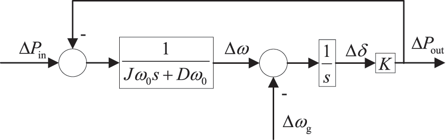
Figure 2: Small signal model of VSG
A robust optimal control method of FVSG is proposed. In the case of input power and grid frequency disturbance, the VSG can maintain relative stability, and the transient process is smooth without oscillation. After the feedforward branch is added to the controller of the VSG, the control block diagram is shown in Fig. 3.
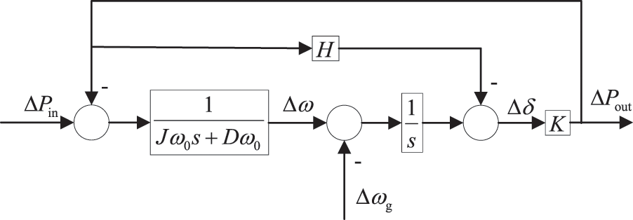
Figure 3: Small signal model of FVSG
In the figure, H is the feedforward gain, and the designed feedforward branch gain H is shown in the equation
The increased feedforward gain does not affect the power linearization process. Therefore, the FVSG and the traditional VSG have the same synchronization coefficient K. After performing an equivalent transformation on the small-signal model in Fig. 3, the small-signal model is shown in Fig. 4 can be obtained.
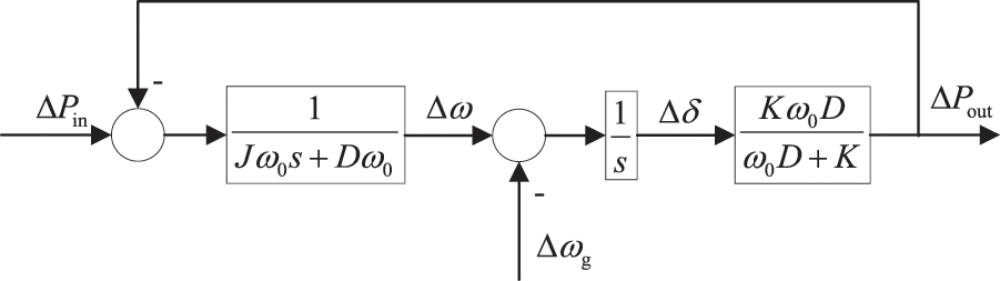
Figure 4: Equivalent transformed FVSG small-signal model
The inertial and frequency modulation responses of FVSG are shown in Fig. 5. During the entire frequency response process, the system’s rate-of-change amplitude, peak frequency, adjustment time, and steady-state frequency appear in sequence in time.
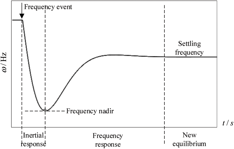
Figure 5: Inertial response and frequency modulation response of FVSG
3 The Relationship between the Frequency Characteristics of FVSG and J, D
3.1 Frequency Response of FVSG Input Power Disturbance
Considering only the influence of input power disturbance on frequency, without considering the impact of grid frequency variation, the equation can be obtained by making
The equation indicates that the system adjusts the FVSG power angle by adjusting the frequency
The oscillation angular frequency
It can be seen from the equation that the larger the moment of inertia J is, the smaller the damping ratio and the smaller the oscillation angular frequency. The larger the damping coefficient D, the larger the damping ratio.
In the case of overdamping, let
The maximum value of
Similarly, when Critical damping, the maximum value of
Similarly, when underdamped, the maximum value of
It can be seen from equations that the larger the moment of inertia J is, the smaller the frequency change of the VSG is, and the better the stability is.
3.2 Frequency Response When Grid Frequency Changes
Considering only the influence of grid frequency disturbance on FVSG frequency, without considering the influence of input power change, let
The equation is a typical second-order system. The oscillation angular frequency
The adjustment time in the case of overdamping and critical damping is relatively long and is not considered.
When underdamped, the adjustment time ts can be approximately expressed as an equation with an allowable error of 2%.
4 The Relationship between K, J of FVSG and the Capacity of Energy Storage Equipment and Its Charge-Discharge Characteristics
The energy storage device is directly related to the input power of the FVSG and the grid frequency disturbance, as well as the inertia coefficient and damping coefficient of the FVSG. The configuration of FVSG energy storage parameters is mainly to determine the inertia coefficient and damping coefficient according to the actual demand. The demand for energy storage is then determined based on the parameters of the FVSG, input power, and grid frequency disturbance. The following is mainly analyzed from two aspects of input power and grid frequency disturbance.
4.1 When the FVSG Input Power is Disturbed
When only analyzing the influence of input power disturbance on frequency, without considering the impact of grid frequency disturbance, let
The equation can be obtained from Fig. 1.
Thus, the charging and discharging power of the energy storage device can be obtained as in equation
The equation can be obtained from the work below:
According to the physical meaning of inertia, the equation can be obtained
Equation is the standard second-order transfer function model. The following analysis is divided into 3 cases according to different damping ratios, and the case of negative damping (ζ< 0) is not considered because it is unstable.
When the system is overdamped (ζ>1), the model shown in the equation has two different real roots.
The equation can be written as such
where, T1 = 1/p1, T2 = 1/p2.
The equation can be expressed as a cascade of two first-order systems when the damping coefficient is much larger than 1, when the pole p2 is far from the imaginary axis and can be neglected. Therefore, the transfer function model shown in the equation above can be simplified to a first-order system as shown in equation below:
Generally, the step response reaches 95% to 98% of the steady-state value after aT1 (where a takes the value of 3 to 4) time. Therefore, it can be considered that in the overdamped case, the regulation time of VSG, which is the response time required for energy storage, is shown in the equation below:
When
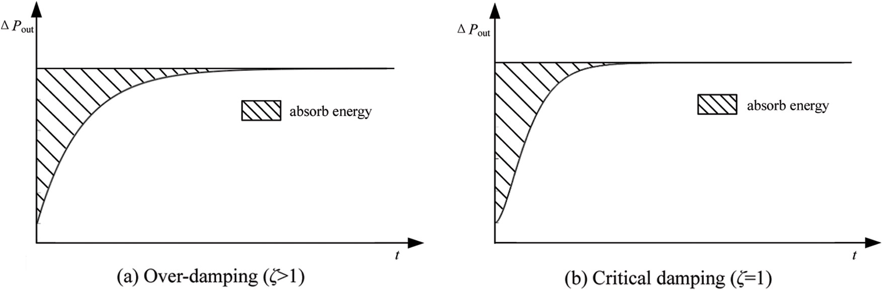
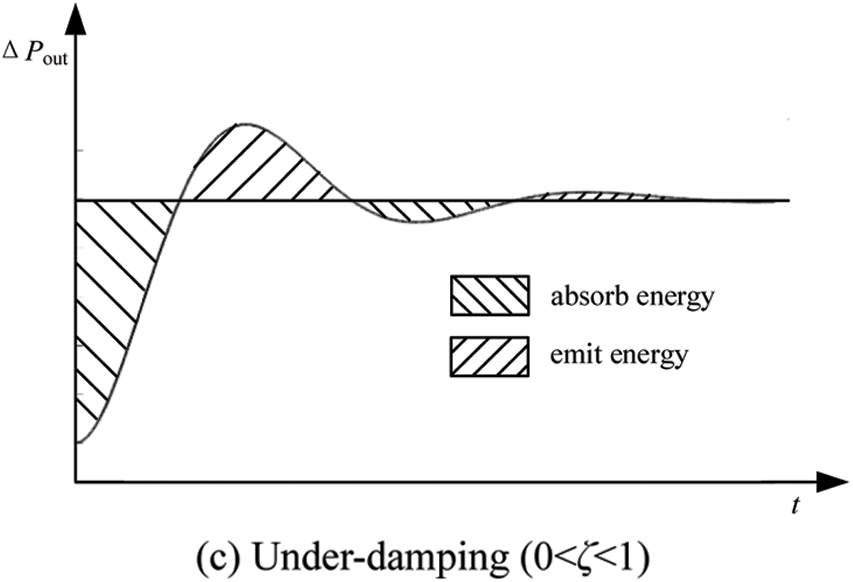
Figure 6: The step response process of FVSG with different damping
Therefore, it is known that when the input power is disturbed, the maximum charge and discharge energy of the energy storage device is also the minimum capacity of the energy storage device, and the minimum capacity of the required configuration of the energy storage capacity is shown in the equation.
When the system is critically damped (ζ = 1), the transfer function shown in the equation has two identical real roots.
Thus, the mathematical model can be expressed as an equation
where,
Similar to the case of over-damping, the regulation time of the system at this time
When
When the system is underdamped (0<ζ<1), the equation has two characteristic roots with opposite numbers of each other.
Let
The time to reach the steady-state value for the first time is shown in the equation
The regulation time of the system is shown in the equation
where, 0<ζ<1, ts1, ts2 are the times of 95% and 98% overshoot, respectively, which are also the response times required by the energy storage device. The maximum charge/discharge energy of the energy storage device is obtained when the steady-state value is reached for the first time. The energy absorbed by the energy storage device throughout the step process, which is the area of the shaded part when the steady-state is reached as shown in Fig. 6c, is also the minimum capacity of the energy storage device and the minimum capacity of the required configuration of the energy storage capacity, as shown in equation
In the case of over-damping, critical damping, and under-damping, the inertia coefficient J is less than, equal to, and greater than
4.2 FVSG Grid Frequency Disturbance
When only the influence of input power disturbance on frequency is analyzed, and the influence of grid frequency disturbance is not considered, let in Fig. 4, we can obtain equation
The equation can be obtained from the following:
According to the physical meaning of inertia, equation can be obtained as the following:
The charging and discharging of the energy from and of energy storage device consists of two main components: one is the difference between the output power of the FVSG and the input power after reaching the new steady-state due to the change in the frequency of the grid, and its charging and discharging power value is
If it cannot be regulated by the input power, this part of the energy storage capacity demand is
The equation is the second-order transfer function model. The following analysis is performed in 3 cases according to different damping ratios, and the case of negative damping (ζ < 0) is not considered because it is unstable.
When the system is overdamped (ζ>1), the mathematical model shown in the equation has two different real roots.
When
Therefore it is known that when the grid frequency changes, the maximum charge and discharge energy of the energy storage device is also the minimum capacity of the energy storage device. The minimum capacity of the required configuration of the energy storage capacity needs to satisfy the equation.
When the system is critically damped (ζ = 1), the transfer function shown in the equation has two identical real roots.
When
When the system is underdamped (0<ζ<1), the equation has two characteristic roots with opposite numbers of each other.
When the steady-state value is reached, the maximum charge/discharge energy of the energy storage device is obtained. The energy absorbed by the energy storage device throughout the step process is the area of the shaded part in Fig. 6c when the steady-state is reached, which is also the minimum capacity of the energy storage device and the minimum capacity of the required configuration of the energy storage capacity, as shown in the equation
In the case of over-damping, critical damping and under-damping, the inertia coefficient J is less than, equal to and greater than
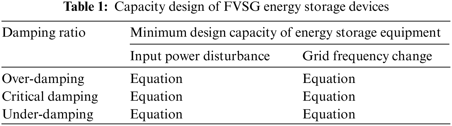
In summary, although different J and D parameters correspond to different ζ and different dynamic response characteristics, the minimum capacity required for the configuration of the energy storage unit in VSG has a consistent solution. The underdamped and critically damped cases have the same expressions for the energy storage capacity requirement, and the overdamped case is different. Table 1 shows the minimum capacity required to be configured for the energy storage unit.
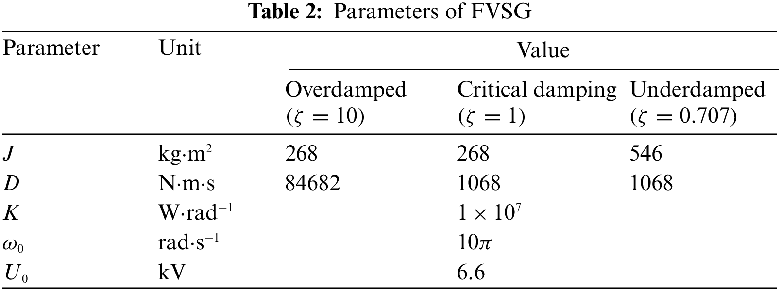
In order to verify the relationship between the charging and discharging power and capacity parameters of the energy storage device and the inertia coefficient and damping coefficient FVSG. Use Matlab/Simulink to build a simulation model. The relevant parameter settings are shown in Table 2.
In the simulation of charging and discharging energy, when the FVSG input power is disturbed,
5.1 FVSG Robustness Optimization Verification
The under-damped parameters in Table 2 are selected to verify the robustness of the FVSG. The results are shown in Fig. 7.
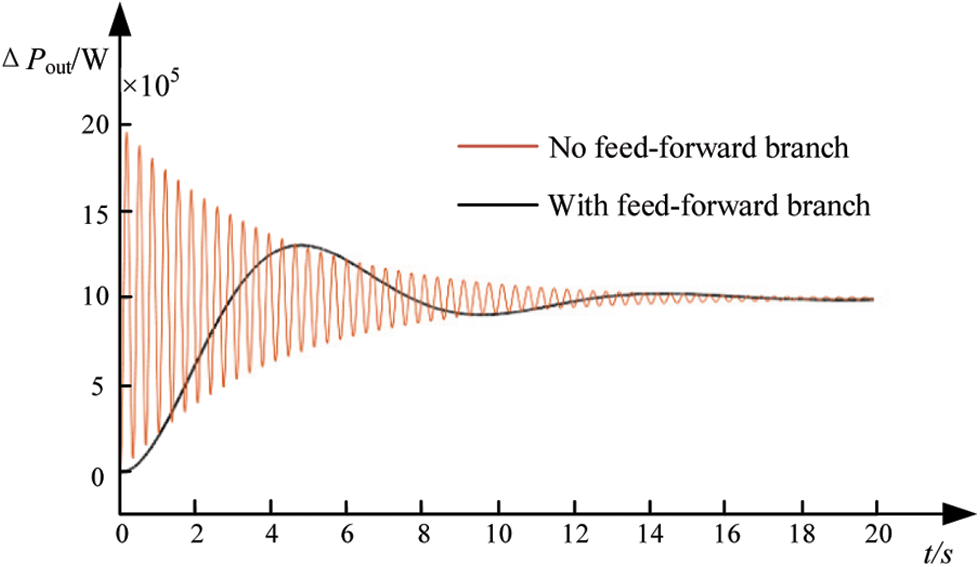
Figure 7: Comparison of output power with and without the feedforward branch during perturbation
It can be seen from the Fig. 7 that the output power of the VSG with the feedforward branch changes smoothly when the system is disturbed by the input power or when the grid frequency changes, and eventually stabilizes gradually. In contrast, the output power of the VSG without feedforward branching changes dramatically when the system is subjected to input power disturbance or grid frequency change, and then stabilizes after a period of time. Therefore, the VSG with feedforward branching facilitates the stable output power change.
5.2 Verification of the Relationship between FVSG Parameters and Frequency Characteristics
The simulation curve of the frequency response when the input power is disturbed is shown in Fig. 8.
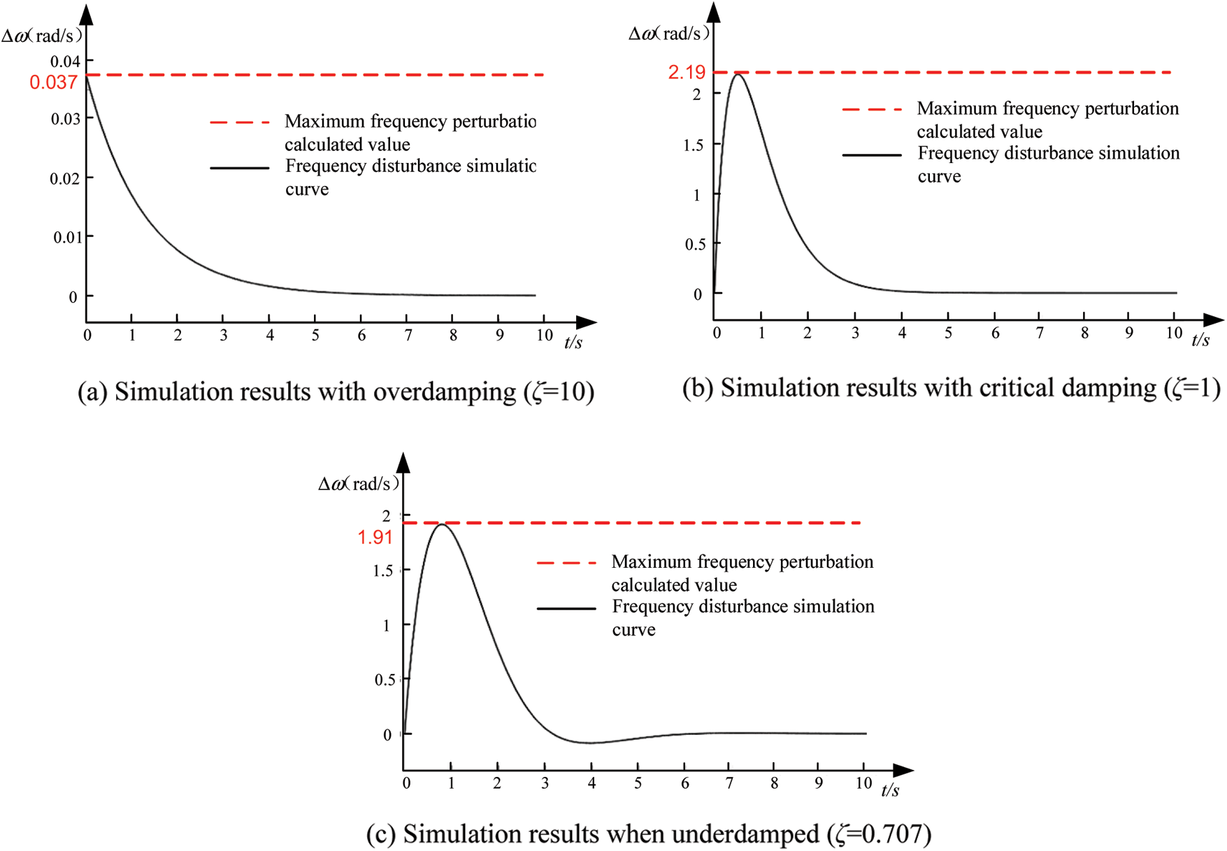
Figure 8: Simulation diagram of frequency characteristics of FVSG when input power is perturbed
The simulation results in Fig. 8 verify the equation.
When the grid frequency is disturbed, the critical damping parameters in Table 2 are used, and the frequency response time simulation curve FVSG is shown in Fig. 9.
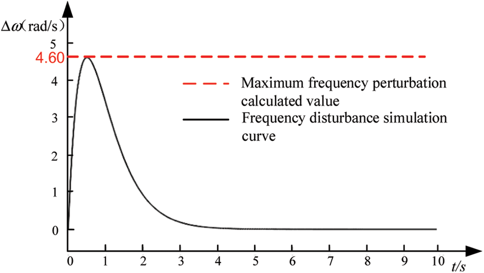
Figure 9: Simulation diagram of frequency characteristics of FVSG when grid frequency is disturbed
The simulation results in Fig. 9 verify the equation.
5.3 Verification of the Relationship between FVSG Parameters and the Capacity of Energy Storage Equipment
The parameters of Table 2 are selected for the design and the results are shown in Fig. 10 by simulating the Emax equation.
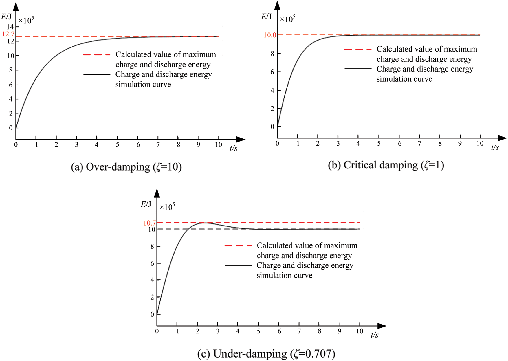
Figure 10: Simulation diagram of FVSG parameters and capacity of energy storage equipment
The simulation results in Fig. 10 verify the equation, respectively.
The minimum energy storage device design should meet the maximum value of charging and discharging energy to ensure the maximum charging and discharging demand required when output power disturbances or grid frequency changes occur.
The parameters of Table 2 under-damping are selected, and the inertia coefficient J and damping coefficient D are changed respectively to simulate the output power, and the results are shown in Fig. 11.
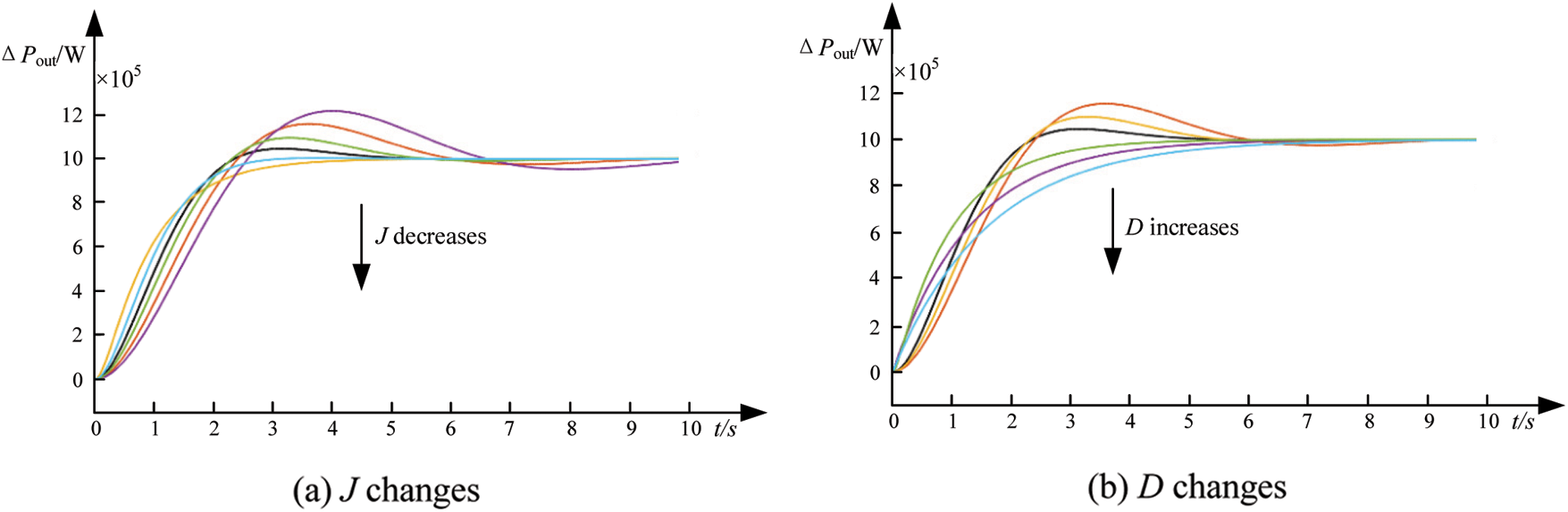
Figure 11: Effect of FVSG parameters on output power
It can be seen from Fig. 11 that the smaller the inertia coefficient J of FVSG, the shorter the output power adjustment time and the smaller the output power variation rate. the larger the damping coefficient D of FVSG, the shorter the output power adjustment time and the smaller the output power variation rate, the smaller the oscillation amplitude, and the better the anti-interference performance of FVSG.
As can be seen from Fig. 11, when the input power is disturbed, the output power increases, then the energy storage unit is required to absorb the power and maintain the stability of the output power. From the perspective of the second-order output power response performance of the VSG, when the damping factor is equal to 0.707, the rate of change of the output power of the VSG is small and the adjustment time is small.
In the actual selection of parameters, it is also necessary to combine with the actual situation, a comprehensive cost-effective consideration, and the selection of appropriate parameters together.
In this paper, the relationship among frequency characteristics, inertia coefficient, damping coefficient, and energy storage capacity of FVSG is deduced in detail. Matlab/Simulink carries out the simulation verification. Research indicates:
(1) FVSG robustness is optimised to maintain its relative stability during input power perturbations and grid frequency changes, improving the adaptiveness of the parameters.
(2) Changing the inertia and damping coefficients has a greater impact on the fluctuation of the output power. The smaller the inertia coefficient and the larger the damping coefficient, the better the stability of the output power. Combined with economic considerations, the FVSG has better immunity to interference at a damping factor of 0.707.
(3) In order to improve the immunity of the FVSG, the inertia and damping coefficients need to be increased, as well as a larger capacity of the energy storage device. When the energy storage capacity of the FVSG is insufficient, the output of the FVSG will not be controlled as expected and will cause voltage fluctuations. Therefore, the actual design has to meet the minimum charge and discharge requirements of the FVSG.
Acknowledgement: This paper is completed under the careful guidance of my tutor. The teacher’s profound professional knowledge, rigorous academic attitude, excellent work style, tireless noble ethics, noble kind of self-discipline and leniency, and approachable and straightforward personality charm have a far-reaching impact on me. Not only did I set a lofty academic goal and master the basic research methods, but it also made me understand many ways to deal with people and circumstances. From the topic selection to the completion of this paper, each step is completed under the tutor’s guidance, and the teacher has devoted a lot of effort. I want to express my high respect and heartfelt thanks to the teacher!
Funding Statement: National Key Research and Development Plan Project (2017YFB1201003-20), Quality Inspection, Monitoring and Operation and Maintenance Guarantee Technology of New Power Supply System Vehicles for Urban Rail Transit and Their on-Board Energy Storage Technology.
Conflicts of Interest: The authors declare that they have no conflicts of interest to report regarding the present study.
References
1. Yan, X. W., Zhang, W. C. (2019). Review of VSG control-enabled universal compatibility architecture for future power systems with high-penetration renewable generation. Applied Sciences, 9(7), 1484. DOI 10.3390/app9071484. [Google Scholar] [CrossRef]
2. Lopes, J. A. P., Hatziargyriou, N., Mutale, J. (2007). Integrating distributed generation into electric power systems: A review of drivers, challenges and opportunities. Electric Power Systems Research, 77(9), 1189–1203. DOI 10.1016/j.epsr.2006.08.016. [Google Scholar] [CrossRef]
3. Yan, X. W., Xu, Y. (2019). Multiple time and space scale reactive power optimization for distribution network with multi-heterogeneous RDG participating in regulation and considering network dynamic reconfiguration. Transactions of China Electrotechnical Society, 34(20), 4358–4372. DOI 10.19595/j.cnki.1000-6753.tces.181933. [Google Scholar] [CrossRef]
4. Zhang, W. C., Liang, H. F., Bin, Z. (2012). Review of DC technology in future smart distribution grid. IEEE PES Innovative Smart Grid Technologies, pp. 1–4. Tianjin, China. [Google Scholar]
5. Guarnieri, M. (2015). More light on information. IEEE Industrial Electronics Magazine, 9(4), 58–61. DOI 10.1109/MIE.2015.2485182. [Google Scholar] [CrossRef]
6. Zhang, C. Y., Dou, X. B., Sheng, W. X. (2020). A robust virtual synchronization control strategy for distri-buted photovoltaic clusters. Proceedings of the CSEE, 40(2), 510–521. DOI 10.13334/j.0258-8013.pcsee.182424. [Google Scholar] [CrossRef]
7. Albu, M., Visscher, K., Creanga, D. (2009). Storage selection for DG applications containing virtual synchronous generators. IEEE Bucharest PowerTech, pp. 1–6. Bucharest, Romania. [Google Scholar]
8. Falahi, G., Huang, A. (2014). Low voltage ride through control of modular multilevel converter based HVDC systems. 40th Annual Conference of the IEEE Industrial Electronics Society, pp. 4663–4668. Dallas, TX, USA. [Google Scholar]
9. Cheng, M., Zhu, Y. (2014). The state of the art of wind energy conversion systems and technologies: A review. Energy Conversion and Management, 88, 332–347. DOI 10.1016/j.enconman.2014.08.037. [Google Scholar] [CrossRef]
10. Zhong, Q. C. (2017). Power-electronics-enabled autonomous power systems: Architecture and technical routes. IEEE Transactions on Industrial Electronics, 64(7), 5907–5918. DOI 10.1109/TIE.2017.2677339. [Google Scholar] [CrossRef]
11. Geng, H., Yang, G. (2018). Modeling framework of voltage-source converters based on equivale-ence with synchronous generator. Modern Power Systems, 6(6), 1291–1305. DOI 10.1007/s40565-018-0433-1. [Google Scholar] [CrossRef]
12. Zhang, B. Q., Hu, C. B., Ma, L. F. (2019). Active power quality control for microgrid with virtual synchro-nous generator based on small-signal stability analysis. Automation of Electric Power Systems, 43(23), 210–222. [Google Scholar]
13. Chen, J. K., Zeng, Q., Xin, Y. C. (2020). Secondary frequency regulation control strategy of MMC-MTDC converter based on improved VSG. Power System Technology, 44(4), 1428–1436. DOI 10.13335/j.1000-3673.pst.2019.1227. [Google Scholar] [CrossRef]
14. Daili, Y., Harrag, A. (2019). New model of multi-parallel distributed generator units based on virtual synchronous generator control strategy. Energy, Ecology and Environment, 4(5), 222–232. DOI 10.1007/s40974-019-00128-3. [Google Scholar] [CrossRef]
15. Yan, X. W., Cui, S., Chang, W. (2021). Primary frequency regulation control strategy of doubly-fed induction generator considering supercapacitor SOC feedback adaptive adjustment. Transactions of China Electrotechnical Society, 36(5), 1027–1039. [Google Scholar]
16. Yan, X. W., Lü, J. W., Jia, J. X. (2020). Two-stage active standby photovoltaic virtual synchronous machine control strategy. Power System Protection and Control, 48(15), 61–68. [Google Scholar]
17. Gao, J. R., Li, G. J., Wang, K. Y., Wu, P., Yu, Z. M. (2020). Control of grid-connected PV-battery virtual synchronous machine considering battery charging/discharging power limit. Automation of Electric Power Systems, 44(4), 134–141. [Google Scholar]
18. Lu, F. Z., He, A. R., Hou, K. (2019). Low-voltage ride-through control strategy of virtual synchronous generator based on the all-pass filter. Electric Power Automation Equipment, 39(5), 176–181. DOI 10.16081/j.issn.1006-6047.2019.05.026. [Google Scholar] [CrossRef]
19. Alipoor, J., Miura, Y., Ise, T. (2015). Power system stabilization using virtual synchronous generator with alternating moment of inertia. IEEE Journal of Emerging and Selected Topics in Power Electronics, 3(2), 451–458. DOI 10.1109/JESTPE.2014.2362530. [Google Scholar] [CrossRef]
20. Li, D., Zhu, Q., Lin, S. (2017). A self-adaptive inertia and damping combination control of VSG to support frequency stability. IEEE Transactions on Energy Conversion, 32(1), 397–398. DOI 10.1109/TEC.2016.2623982. [Google Scholar] [CrossRef]
21. Li, X., Chen, G., Ali, M. S. (2019). Improved virtual synchronous generator with transient damping link and its seamless transfer control for cascaded H-bridge multilevel converter-based energy storage system. IET Electric Power Applications, 13(10), 1535–1543. DOI 10.1049/iet-epa.2018.5722. [Google Scholar] [CrossRef]
22. Hong, H. H., Gu, W., Huang, Q. (2019). Power oscillation damping control for microgrid with multiple VSG units. Proceedings of the CSEE, 39(21), 6247–6254. DOI 10.13334/j.0258-8013.pcsee.181088. [Google Scholar] [CrossRef]
23. Zeng, Z., Shao, W. H., Ran, L. (2015). Mathematical model and strategic energy storage selection of virtual synchronous generators. Automation of Electric Power Systems, 39(13), 22–31. DOI 10.7500/AEPS20140901007. [Google Scholar] [CrossRef]
24. Song, Q., Zhang, H., Sun, K. (2017). Improved adaptive control of inertia for virtual synchronous gener-ators in islanding micro-grid with multiple distributed generation units. Proceedings of the CSEE, 37(2), 412–423. DOI 10.13334/j.0258-8013.pcsee.161658. [Google Scholar] [CrossRef]
25. Shi, R., Zhang, X., Hu, C. (2018). Self-tuning virtual synchronous generator control for improving frequency stability in autonomous photovoltaic-diesel micro grids. Journal of Modern Power Systems and Clean Energy, 6(3), 482–494. DOI 10.1007/s40565-017-0347-3. [Google Scholar] [CrossRef]
26. Yang, F., Shao, Y. L., Li, D. D. (2020). A fuzzy adaptive VSG control strategy considering energy storage capacity and constraint of SOC. Power System Technology, 1, 1–12. [Google Scholar]
27. Xing, D. F., Tian, M. X. (2021). Relationship between frequency characteristics of virtual synchronous generator and parameters of energy storage equipment. Power System Technology, 45(9), 3582–3593. DOI 10.13335/j.1000-3673.pst.2020.1490. [Google Scholar] [CrossRef]
28. Meng, J. H., Zhao, P. H., Wang, Y. (2020). Research on the cooperative operation of optical storage system based on virtual inertial control. Power System Technology, 4, 1–12. [Google Scholar]
29. Chen, J., O’Donnell, T. (2019). Parameter constraints for virtual synchronous generator considering stability. IEEE Transactions on Power Systems, 34(3), 2479–2481. DOI 10.1109/TPWRS.59. [Google Scholar] [CrossRef]
30. Chen, J., O’Donnell, T. (2019). Analysis of virtual synchronous generator control and its response based on transfer functions. IET Power Electronics, 12(11), 2965–2977. DOI 10.1049/iet-pel.2018.5711. [Google Scholar] [CrossRef]
Cite This Article
 Copyright © 2022 The Author(s). Published by Tech Science Press.
This work is licensed under a Creative Commons Attribution 4.0 International License , which permits unrestricted use, distribution, and reproduction in any medium, provided the original work is properly cited.
 Downloads
 Citation Tools