
 Submit a Paper
 Propose a Special lssue
 Open Access
ARTICLE
Energy Management of Networked Smart Railway Stations Considering Regenerative Braking, Energy Storage System, and Photovoltaic Units
1 School of Railway Engineering, Iran University of Science and Technology, Tehran, 13114-16846, Iran
2 Department of Electrical and Computer Engineering, University of Kashan, Kashan, 8731753153, Iran
3 Research and Innovational Center for Electrical Engineering (RICE), Faculty of Electrical Engineering, University of West Bohemia (UWB), Pilsen, 30100, Czech Republic
* Corresponding Author: Seyed Saeed Fazel. Email:
Energy Engineering 2023, 120(1), 69-86. https://doi.org/10.32604/ee.2022.024121
Received 24 May 2022; Accepted 10 August 2022; Issue published 27 October 2022
 View Full Text
 Download PDF
Abstract
The networking of microgrids has received significant attention in the form of a smart grid. In this paper, a set of smart railway stations, which is assumed as microgrids, is connected together. It has been tried to manage the energy exchanged between the networked microgrids to reduce received energy from the utility grid. Also, the operational costs of stations under various conditions decrease by applying the proposed method. The smart railway stations are studied in the presence of photovoltaic (PV) units, energy storage systems (ESSs), and regenerative braking strategies. Studying regenerative braking is one of the essential contributions. Moreover, the stochastic behaviors of the ESS’s initial state of energy and the uncertainty of PV power generation are taken into account through a scenario-based method. The networked microgrid scheme of railway stations (based on coordinated operation and scheduling) and independent operation of railway stations are studied. The proposed method is applied to realistic case studies, including three stations of Line 3 of Tehran Urban and Suburban Railway Operation Company (TUSROC). The rolling stock is simulated in the MATLAB environment. Thus, the coordinated operation of networked microgrids and independent operation of railway stations are optimized in the GAMS environment utilizing mixed-integer linear programming (MILP).Graphic Abstract
Keywords
Nomenclature
| Abbreviations | |
| EES | Energy storage system |
| EM | Energy management |
| EMS | Energy management system |
| HESS | Hybrid energy storage system |
| MILP | Mixed-integer linear programming |
| PV | Photovoltaic |
| RBE | Regenerative braking energy |
| RB | Regenerative braking |
| SG | Smart grid |
| SRSEM | Smart railway stations energy management |
| SOE | State of energy |
| Indices and Sets | |
| h, k | Index of railway station h, k = {1, 2,…, H} |
| s | Index of scenario s = {1, 2,…, S} |
| t | Index of time t = {1, 2,…, 24} |
| Parameters | |
| Maximum charging battery rate power in station h [kW per min] | |
| Maximum charging ultracapacitor rate power in station h [kW per min] | |
| Maximum discharging battery rate power in station h [kW per min] | |
| Maximum discharging ultracapacitor rate power in station h [kW per min] | |
| Coefficient of converter loss in station h | |
| Charge/discharge efficiency coefficient for battery in station h | |
| Charge/discharge efficiency coefficient for ultracapacitor in station h | |
| Maximum rate power of regenerative braking (RB) that injected into DC bus in station h [kW] | |
| Sh,k | Maximum power rate that can be exchanged between station h and k [kW] |
| Maximum power that can be purchased from the grid [kW] | |
| Maximum power that can be sold to the utility grid [kW] | |
| Coefficient of transmission loss between station h and k | |
| Variables | |
| Power generated by the photovoltaic (PV) during time interval t for scenario s in station h [kW] | |
| Power demand of station h during time interval t [kW] | |
| Power obtained from regenerative braking energy (RBE) during time interval t in station h [kW] | |
| Amount of power supplied by the utility grid during time interval t for scenario s in station h [kW] | |
| Amount of power sold to the utility grid during time interval t for scenario s in station h [kW] | |
| Transmission power amount from station h to station k during time interval t for scenario s [kW] | |
| Transmission power amount from station k to station h during time interval t for scenario s [kW] | |
| Power used from RBE to charge the battery during time interval t for scenario s in station h [kW] | |
| Power used from RBE to charge ultracapacitor during time interval t for scenario s in station h [kW] | |
| Power used from RBE to inject directly into DC bus during time interval t for scenario s in station h | |
| State of energy (SOE) of the battery of station h during time interval t for scenario s [kWh] | |
| SOE of ultracapacitor during time interval t for scenario s in station h [kWh] | |
| Minimum SOE limit of the battery of station h [kWh] | |
| Maximum SOE limit of the battery of station h [kWh] | |
| Minimum SOE limit of ultracapacitor in station h [kWh] | |
| Minimum SOE limit of ultracapacitor in station h [kWh] | |
| A binary variable of the battery of station h, which its value will be 1 if the battery is charging during the time interval t for scenario s; otherwise, its value would be 0 | |
| A binary variable of ultracapacitor of station h which its value will be 1 if the ultracapacitor is charging during the time interval t for scenario s; otherwise, its value would be 0 | |
The urban railway is considered to be one of the major energy consumption networks. Therefore, energy management in these networks is crucial due to the supply of energy, especially under simultaneity of peak demand of utility grid and peak traffic hours along with technical and economic issues [1]. The smart railway station concept results in the advantages of a smart grid structure, e.g., the mutual power exchange with the utility grid [2], integration of renewable energy resources [3], efficiency increase [4], and system reliability improvement [5]. In addition, the power consumption level in urban railway system during the day is significantly different that causes technical problems as well as power quality problems [6], such as current harmonics, three-phase imbalance condition, and additional reactive power demands for electricity network [7].
The development of urban railway networks requires a suitable structure for accurate energy consumption management. The smart grid structure will achieve important targets like operational cost reduction and environmental pollution [8]. Many studies on the electrical railway network have focused on regenerative braking energy (RBE), and various solutions have been reported to utilize this energy [9].
In [10], authors presented an energy management strategy to coordinate microgrid energy management and on-route train energy consumption based on the maximum economic benefit. A railway energy management architecture based on the smart grid (SG) framework has been introduced by [1] to integrate onboard and wayside energy storage system (ESS), distributed generation units, and train’s load. In [11], an energy management optimization for railway power substations has been presented to coordinate renewable energy sources and storage units. In [12], a method for optimum operation of railway electric energy systems in the presence of renewable resources, RB, and hybrid ESS (HESS), has been presented. Along with the aim of energy and economic savings, the uncertainty related to renewable energies has been considered by [12]. In [13], the integration of smart micro-grid in DC railway systems has been investigated to increase the total energy efficiency of the system. In the presence of HESS, RBE is stored and reused in non-railway consumption. An energy management/control strategy, while the RBE is stored in ESS, has been reported in [14]. The RBE can be reused for the acceleration of vehicles. Consequently, the system efficiency increases and the pantograph voltage profile is improved. In the presence of a DC microgrid, including photovoltaic (PV), ESS, and RBE, Hernandez et al. [15] presented a strategy of power management, converter control, and the influence of the ESS component to charge electric vehicles on railway station parking lots. The train mass changing during the day, which has an effect on RBE, and the uncertainty of initial SOE of ESS were not considered. Authors of [2] proposed energy management of a smart railway station in the presence of PV, RBE, and ESS, while the RBE is stored in ESS and utilized to supply station load. However, through the proposed energy management (EM) model, the whole RBE utilization potential could not be used because the ESS sometimes might be fully charged.
Considering the optimal planning problem for electrical railway systems, Tostado-Véliz et al. [16] proposed an optimal sizing model to find the best-compromised solution for a hybrid battery and super-capacitor energy storage system. Controlling energy flow in a tramway system has been studied by [17] through a techno-economic and environmental analysis. Also, novel patterns concerning existing tramways have been identified in [17]. An optimal scheduling model for a tramway system coordinating the operation of facilities, including PV energy, hydrokinetic turbines, and a biomass gasifier, has been reported by [18]. Additionally, robustness analysis of the system is conducted against future load increases. Furthermore, a comparison has been presented by [19] for two alternative systems to supply tramway traction power, including an upstream power grid and hydrogen charging stations on the depth of discharge and voltage variation.
In order to manage the energy flow in smart energy systems and microgrids, such as smart buildings, Elkholy et al. [20] have proposed an efficient home energy management system, considering energy generation and consumption units deploying a field-programmable gate array (FPGA) unit. Also, in the presence of PV, fuel cells, and wind energy systems, Elkholy et al. [21] presented a smart energy management system by implementing an FPGA unit. A various-goal energy management system based on a two-layer hierarchical control scheme was proposed by [22] to reduce the cost of electricity and obtain free charging of electric vehicles, as future transportation systems, through renewable energy sources.
Tostado-Véliz et al. [23] presented an optimal day-ahead scheduling model for a microgrid through an information gap decision theory (IGDT) framework based on a MILP model. The uncertainties regarding renewable energies, demands, and energy pricing have been considered by [23]. In the presence of green hydrogen-based storage systems, Tostado-Véliz et al. [24] proposed an optimal robust scheduling model. The impacts of different demand response programs on microgrid operation have been studied. Also, a stochastic-interval model was presented by [25] for the optimal operation of charging stations, considering optimistic and pessimistic strategies. In the presence of pumped-hydro and battery energy storage systems, Ahmadi et al. [26] presented an interval-based model coping with the uncertainties. Considering the failure of components, Tostado-Véliz et al. [27] proposed an optimal scheduling model for isolated microgrids based on a stochastic-IGDT framework, which is robust against failures. The various studies in the literature about the uncertainties and their impacts on microgrids highlight the importance of these concerns.
In this paper, a set of smart railway stations are connected together. It has been tried to manage the energy exchanged between them in order to reduce received energy from the utility grid and the operational cost of stations under various conditions. In one of the studied conditions, it is assumed that each smart railway station includes PV panels, the HESS (battery and ultracapacitor), and the load of the station. Also, the RBE can be used as station supply and storage in ESS, or it can be sold to the utility grid. The stochastic behaviors of the initial SOE of ESS and uncertainty of PV power generation are evaluated through a set of scenarios. The changes in the train mass during the day are considered, which affect the RBE and its calculations. The feasibility study is done for investment return. In addition, the networking of smart railway stations’ influence on operational cost has been evaluated through a set of case studies. Also, the smart railway stations energy management (SRSEM) is formulated based on mixed-integer linear programming (MILP).
The main contributions of this paper can be listed as follows:
• Proposing an optimal scenario-based operation model for smart railway stations in the presence of renewable energies and energy storage;
• Coordinating the operation of networked smart stations to reduce the cost of exchanged energy with the upstream power grid;
• Facilitating the usage of recovered energy by trains through the coordination scheme;
• Considering the uncertainties related to PV power generation and the initial state of energy storage;
• Considering the changes in the number of passengers during a day, aiming to accurately forecast the energy flow of the trains, including traction consumption and regenerative profile;
• Investigating the operation of the smart stations under two operational schemes, including independent and coordinated schemes.
The rest of this paper is organized into three sections. The mathematical modeling and the proposed energy management problem are presented in Section 2. Section 3 describes the simulation procedure and reviles the case studies. In addition, the simulation results and a brief discussion are presented in Section 3. In the last section (Section 4), a summary conclusion is provided.
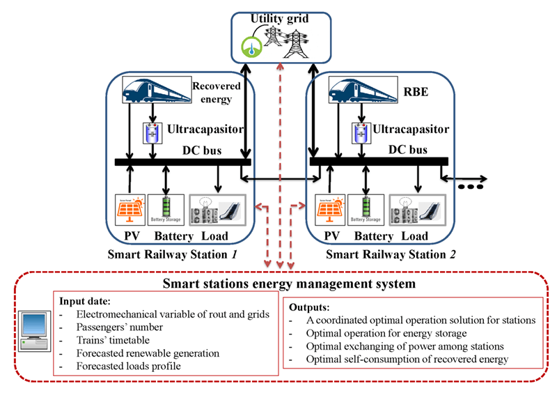
Generally, smart electrical railway stations consist of station load, PV generation units, and ESS. In this study, smart railway stations have been considered as networked microgrids that are able to exchange power with each other, besides the utility grid. The structure and components of smart stations and relevant connections are shown in Fig. 1.

Figure 1: Structure of networked stations
Train power: In order to calculate RBE, the train forces need to be measured. Train power (
In (1), m, v,
In (2),
In the proposed energy management model, to schedule the operation of the facilities based on a mathematical programming framework, the operation, as well as stability constraints related to each element, should be considered and formulated. Hence, the proposed optimization model, representing the optimal operation model, is described in this part.
In addition, H is considered as a set of networked stations, and indices h and k indicate any of the members of the above set. It is assumed that power transmission can be distinguished between the members. Minimizing the total daily operational costs of the stations is considered the objective function of the EM model, as shown in (3).
Moreover, variable (
In this model, the time interval t is considered one minute (approximate time of train braking in the stations). In addition, (
For a stable operation of stations, a collection of the time-dependent equation in each scenario should be met [29,30].
Power balance: Eq. (5) indicates that in each time interval and scenario, generated power by PV units
Exchanged power constraints: Parameter (
The capacity of power exchange with the utility grid is determined based on (8) and (9). On the other hand, stations are able to either sell or purchase power at the same time. This limitation is applied using a binary variable
RBE modeling: The RBE in each station can be used for different utilizations, including direct injection to the DC bus and charging the ultracapacitor. The amount of effective RBE that is injected directly to the DC bus of station h (
ESS modeling: Technical specifications of the equipment, like capacity and charge/discharge rate, may have different values in each station. Therefore, any of these specifications has index h and takes value based on the specification of each station. The effective power of the battery/ultracapacitor (
As seen, (
3 Simulation Results and Discussions
3.1 Case Study and Test Results
The MILP model has run in GAMS software v.24.1.2 with Intel Xeon 2.80 GHz processor and Windows server 2008 operating system, and simulation results are gained by CPLEX v.12 solver.
To calculate the RBE, the train movement must be simulated dynamically. For this purpose, route profile, route plan, route headway, and train specifications are required. It is necessary to mention that train movement has been simulated with Intel core i7, 2.20 GHz processor, and Windows 8.1 operating system in MATLAB environment. The proposed MILP model can be applied to any number of stations. In this study, the model has been operated on three stations of line 3 of Tehran Urban and Suburban Railway Operation Company (TUSROC), namely M3, N3, and O3. Line 3 of the TUSROC is 37 km long with 26 stations. Figs. 2 and 3 show train loading percentage during the day and RB power profile of station O3, respectively.

Figure 2: Train loading percentage during the day

Figure 3: RB power profile during a day of station O3
In this study, station load demand is investigated, and those issues related to traction energy demand are not considered. Also, power exchange between M3 and O3 stations is transmitted through the N3 station. Fig. 4. shows the stations’ load profile. Station load consists of consumptions like lighting, escalator, elevator, and ventilation. The time of use (TOU) pricing scheme is applied. The energy price during off-peak hours (23:00 to 07:00), mid-peak hours (07:00 to 11:00 and 17:00 to 19:00) and on-peak hours (11:00 to 17:00 and 19:00 to 23:00) is considered to be 0.02, 0.04, and 0.09 $/kWh, respectively.

Figure 4: Daily stations load profiles
It should be noted that purchasing and selling energy prices are assumed to be equal. As all the three stations have one operator, power transmission among the stations will have no charges.
The initial SOE of ESS is considered an uncertain parameter. For this purpose, W set is defined, including the scenarios of the initial value of energy storage devices. The initial value in the first scenario is equal to the maximum allowable SOE, and the same in the second scenario is the minimum allowable SOE of the storage devices. The probability of any of the members is assumed to be equal. Using these two scenarios, the influence of the best and worst cases on daily operational costs will be taken into consideration.
Since the PV generation is uncertain, set R is defined, consisting of 12 solar irradiation and temperature scenarios. This set is used for producing PV generation profiles.
It should be noted that solar irradiation depends on different factors, mainly environmental and seasonal conditions [32].
RERs, such as PV units, are probabilistic power generators. As a result, their uncertainties need to be considered. Also, simulation methods based on stochastic processes, such as MCS, are becoming more popular and useful. The MCS-based approaches are capable of accurately analyzing uncertainties, but their computation time poses a major challenge. It is crucial to understand the computation time of MCS-based approaches, especially if you are trying to solve an optimization problem or make a decision in real-time. As a result, new fast methods for assessing energy system uncertainty have gained much attention, particularly analytical or scenario-based methods. This paper aims to mitigate the challenges of MCS-based, while obtained results are adequately precise from the viewpoint of uncertainty modeling.
In order to model the problem stochastically, a scenario set S is defined, consisting initial SOE of ESS and PV power generation scenarios with 24 members (2 * 12). Also,
MATLAB software has been used to produce PV generation scenarios based on the MCS approach, and the following steps are done:
1- By means of Tehran irradiation and temperature data taken from [33], a total of 250 solar irradiation scenarios have been produced for a complete day in each season by the Monte Carlo simulation (MCS) [34].
2- The probability of each scenario is assumed to be 0.001 by putting 1000 solar irradiation scenarios together in one year (250 * 4).
3- To reduce the scenarios, the backward reduction technique is applied, and finally, 12 scenarios with a new probability are selected [35].
4- The profile of PV generation power has been determined after converting irradiation and temperature scenarios based on PV panel specifications by the manufacturers [36].
Fig. 5 shows the profile of PV generation power in station N3 for different scenarios. Seasonal influence on maximum PV generation is evident.

Figure 5: PV generated power profile of station N3 for different scenarios during the day
Indeed, using equipment like PV panels, ESS, or RB, power utilization in each station depends on the existing capacities and relevant infrastructures. For instance, PV panels require suitable space for installation. As the subway stations are located inside cities, the capacity of installed PV in each station depends on its accessible space. In addition, the required space for ESSs in each station is limited. There are also important remarks on RBE. Table 1 shows the technical specifications of the understudy test system’s elements.

To investigate the proposed energy management model, daily operational costs in each station, exchanged power between the stations, SOE of batteries, and received energy from the grid during on-peak hours, are analyzed. Eight different case studies have been considered based on the absence/ presence of elements like PV, ESS, and RBE, as shown in Table 2. For each case study, two operational modes are defined, including stations’ independent operational mode and interconnected operational mode, and all of these modes are evaluated with the scenario set S.

Table 3 indicates the daily operational costs of stations. The operational cost of one station under the stations’ interconnection may increase more than the stations’ independent operational mode, but the total operational cost of stations will decrease. For example, in case 6, the operational cost of two stations N3 and O3 has decreased by 3.10% and 18.71%, respectively, and the same has increased by 17.5% for station M3. However, the total operational cost of these stations has decreased by 2.49%.

The decrease in operational cost depends on accessible generated power in the stations’ interconnection operational mode. In other words, an increase in energy generation elements in the stations will increase the possibility of power interchange between stations. As using of RBE is not limited to storage, it will be possible to use this energy all the time since the storage device may be fully charged and RBE cannot be used at some moments. In addition, the possibility of power transmission between stations results in maximum utilization of all the energy generation and storage resources. Hence, as it can be seen, in cases one to four, there is no significant difference between the operation costs in the two operational modes.
Furthermore, the average interchanged power by the stations in scenarios 5 and 1 is shown in Table 4. Scenario 5 has the lowest, and scenario 1 has the most PV power generation among the R set. It is evident that PV power generation is more in scenario 1, which leads to an increase in power transmission between stations.

Fig. 6 shows the SOE of batteries in case 7 for scenario 19. Obviously, the SOE of batteries will increase more quickly after RBE becomes accessible at 05:00. In addition, their charge/discharge procedure can be observed depending on energy price alterations. It is worth mentioning that battery behavior in two stations, M3 and O3, for all the scenarios under stations’ interconnected and independent operational modes, is similar since both stations are able to buy/sell power from/to the utility grid. An interesting situation takes place in the battery behavior of station N3 under the independent operational mode, which is different in comparison with other stations, and the whole charging capacity was not used before the first price increase since the second station cannot sell power to the utility grid (Fig. 6, scenario 19). Under the station’s interconnected operational mode, all the batteries have almost similar behaviors, and the level of accessible saved energy in the stations is more than in the independent operational mode.

Figure 6: Variations of battery SOE and energy price in each station in case 7 for scenario 19 during a day. M1: Stations interconnected operational mode, M2: Stations independent operational mode
As mentioned before, the supply of required power for urban railways during on-peak hours is considered to be one of the challenges for the utility grid. Table 5 indicates received energy from the grid during on-peak hours (19:00 to 23:00) for scenario 1.

The power purchased from the utility grid by stations in case 7 (for a short time interval and under stations’ interconnected operational mode) is shown in Fig. 7. It is worthy to note that for scenario 1 sold power is stable compared to scenario 5.

Figure 7: Power purchased from the utility grid by stations in selected scenarios
As revealed by test results and defining different cases, it has been tried to study and distinguish the impacts of deploying each facility in smart railway stations. It is evident that the total daily operational cost in the presence of PV, RB, and ESS has decreased more than the base case in which the load of the station is supplied just by the utility grid. However, from a planning and expansion perspective, different costs and factors should be taken into account, including investment, maintenance, and replacement costs, which are considered in future works. The biggest total cost reduction is evident under the stations’ interconnection operational mode of case 7, where cost reduction is 48.60% in comparison with the base case and 3.67% in comparison with case 7 under the stations’ independent operational mode. Hence, based on the results, it can be concluded that the coordination scheme brings more economic benefits for the SRS since the stations can share their facilities, including storage. Also, as the RBE has a high power density, through coordination mode, more RBE can be used since more loads are available to provide and more capacity to store energy exists.
Another aspect of this study that claims attention is the execution time of calculations and optimization by the proposed method. A reasonable computational time is one of the advantages of the proposed method compared to MCS-based ones. Indeed, the proposed method for optimal operation of smart railway systems would be adequately fast and precise. Thus, the scalability of the proposed method is satisfying, and the proposed method can be applied to large test systems.
This paper presented an energy management model for smart railway stations based on MILP, which is formulated stochastically. Considering energy storage systems, PV generation units, and RBE utilization, two different operational modes (interconnected and independent operational modes of the smart stations), have been introduced to study their impacts on the system’s operation. Also, a set of scenarios to evaluate the effects of solar irradiation and initial SOE of ESS uncertain behavior have been utilized. In addition, in order to calculate the amount of available RBE, trains’ motion and related power flow calculation have been simulated considering the changes in the number of passengers during a day. Simulation results in the presence of all elements, including PV, ESSs, and RBE, indicated a cost reduction of 48.6% for the whole stations in interconnected operational mode. In addition, daily operation costs in interconnected operational mode indicate a cost reduction of 3.67% in comparison with independent operation of stations. Another challenge caused by the urban electrical railway system is the coincidence of consumption peak and passenger flow peak. The amount of received energy from the utility grid during the energy consumption peak hours by means of the proposed model would decrease by 24% in the presence of all elements under the station’s interconnected operation mode. Developing the model from an optimal planning perspective as well as proposing a fairly cost allocation mechanism for the entities are considered for future works.
Funding Statement: The authors received no specific funding for this study.
Conflicts of Interest: The authors declare that they have no conflicts of interest to report regarding the present study.
References
1. Khayyam, S., Ponci, F., Goikoetxea, J., Recagno, V., Bagliano, V. et al. (2016). Railway energy management system: Centralized-decentralized automation architecture. IEEE Transactions on Smart Grid, 7(2), 1164–1175. DOI 10.1109/TSG.2015.2421644. [Google Scholar] [CrossRef]
2. Sengor, I., Kilickiran, H. C., Akdemir, H., Kekezoglu, B., Erdinc, O. et al. (2018). Energy management of a smart railway station considering regenerative braking and stochastic behaviour of ESS and PV generation. IEEE Transactions on Sustainable Energy, 9(3), 1041–1050. DOI 10.1109/TSTE.2017.2759105. [Google Scholar] [CrossRef]
3. Akbari, S., Fazel, S. S., Jadid, S. (2021b). Optimal operation of a smart railway station based on a multi-energy hub structure considering environmental perspective and regenerative braking utilization. Energy Science & Engineering, 9(9), 1614–1631. DOI 10.1002/ese3.937. [Google Scholar] [CrossRef]
4. Collotta, M., Pau, G. (2017). An innovative approach for forecasting of energy requirements to improve a smart home management system based on BLE. IEEE Transactions on Green Communications and Networking, 1(1), 112–120. DOI 10.1109/TGCN.2017.2671407. [Google Scholar] [CrossRef]
5. Hartwig, K., Kockar, I. (2016). Impact of strategic behavior and ownership of energy storage on provision of flexibility. IEEE Transactions on Sustainable Energy, 7(2), 744–754. DOI 10.1109/TSTE.2015.2497967. [Google Scholar] [CrossRef]
6. Hu, S., Li, S., Li, Y., Krause, O., Zare, F. (2018). A comprehensive study for the power flow controller used in railway power systems. IEEE Transactions on Industrial Electronics, 65(8), 6032–6043. DOI 10.1109/TIE.2017.2786201. [Google Scholar] [CrossRef]
7. Akbari, S., Fazel, S. S. (2022). Multistage multiobjective optimization for optimal energy management of the connected cophase traction power system. International Transactions on Electrical Energy Systems, 2022, 7217478. DOI 10.1155/2022/7217478. [Google Scholar] [CrossRef]
8. Khayyam, S., Berr, N., Razik, L., Fleck, M., Ponci, F. et al. (2018). Railway system energy management optimization demonstrated at offline and online case studies. IEEE Transactions on Intelligent Transportation Systems, 19(11), 3570–3583. DOI 10.1109/TITS.2018.2855748. [Google Scholar] [CrossRef]
9. Akbari, S., Fazel, S. S., Jadid, S. (2021). Optimal coordinated operation of integrated energy hubs, considering regenerative braking utilization. IET Electrical Systems in Transportation, 11(4), 362–376. DOI 10.1049/els2.12032. [Google Scholar] [CrossRef]
10. Novak, H., Vašak, M., Lešić, V. (2016). Hierarchical energy management of multi-train railway transport system with energy storages. 2016 IEEE International Conference on Intelligent Rail Transportation (ICIRT), Birmingham, UK. [Google Scholar]
11. Pankovits, P., Pouget, J., Robyns, B., Delhaye, F., Brisset, S. (2014). Towards railway-smartgrid: Energy management optimization for hybrid railway power substations. IEEE PES Innovative Smart Grid Technologies, Europe. [Google Scholar]
12. Aguado, J. A., Racero, A. J. S., Torre, S. D. L. (2018). Optimal operation of electric railways with renewable energy and electric storage systems. IEEE Transactions on Smart Grid, 9(2), 993–1001. DOI 10.1109/TSG.2016.2574200. [Google Scholar] [CrossRef]
13. Nasr, S., Iordache, M., Petit, M. (2014). Smart micro-grid integration in DC railway systems. IEEE PES Innovative Smart Grid Technologies, Europe. [Google Scholar]
14. Ciccarelli, F., Pizzo, A. D., Iannuzzi, D. (2014). Improvement of energy efficiency in light railway vehicles based on power management control of wayside lithium-ion capacitor storage. IEEE Transactions on Power Electronics, 29(1), 275–286. DOI 10.1109/TPEL.2013.2253492. [Google Scholar] [CrossRef]
15. Hernandez, J. C., Sutil, F. S. (2016). Electric vehicle charging stations feeded by renewable: PV and train regenerative braking. IEEE Latin America Transactions, 14(7), 3262–3269. DOI 10.1109/TLA.2016.7587629. [Google Scholar] [CrossRef]
16. Tostado-Véliz, M., Arévalo, P., Jurado, F. (2021). An optimization framework for planning wayside and on-board hybrid storage systems for tramway applications. Journal of Energy Storage, 43(4), 103207. DOI 10.1016/j.est.2021.103207. [Google Scholar] [CrossRef]
17. Cano, A., Arévalo, P., Benavides, D., Jurado, F. (2021). Sustainable tramway, techno-economic analysis and environmental effects in an urban public transport. A comparative study. Sustainable Energy, Grids and Networks, 26, 100462. DOI 10.1016/j.segan.2021.100462. [Google Scholar] [CrossRef]
18. Arévalo, P., Cano, A., Benavides, J., Jurado, F. (2021). Feasibility study of a renewable system (PV/HKT/GB) for hybrid tramway based on fuel cell and super capacitor. IET Renewable Power Generation, 15(3), 491–503. DOI 10.1049/rpg2.12056. [Google Scholar] [CrossRef]
19. Arévalo, P., Cano, A., Jurado, F. (2020). Comparative study of two new energy control systems based on PEMFC for a hybrid tramway in Ecuador. International Journal of Hydrogen Energy, 45(46), 25357–25377. DOI 10.1016/j.ijhydene.2020.06.212. [Google Scholar] [CrossRef]
20. Elkholy, M. H., Metwally, H., Farahat, M. A., Nasser, M., Senjyu, T. et al. (2022). Dynamic centralized control and intelligent load management system of a remote residential building with V2H technology. Journal of Energy Storage, 52(4), 104839. DOI 10.1016/j.est.2022.104839. [Google Scholar] [CrossRef]
21. Elkholy, M. H., Metwally, H., Farahat, M. A., Senjyu, T., Elsayed Lotfy, M. (2022). Smart centralized energy management system for autonomous microgrid using FPGA. Applied Energy, 317(2), 119164. DOI 10.1016/j.apenergy.2022.119164. [Google Scholar] [CrossRef]
22. Ben Arab, M., Rekik, M., Krichen, L. (2022). Suitable various-goal energy management system for smart home based on photovoltaic generator and electric vehicles. Journal of Building Engineering, 52(6), 104430. DOI 10.1016/j.jobe.2022.104430. [Google Scholar] [CrossRef]
23. Tostado-Véliz, M., Kamel, S., Hasanien, H. M., Turky, R. A., Jurado, F. (2022b). Uncertainty-aware day-ahead scheduling of microgrids considering response fatigue: An IGDT approach. Applied Energy, 310(1), 118611. DOI 10.1016/j.apenergy.2022.118611. [Google Scholar] [CrossRef]
24. Tostado-Véliz, M., Kamel, S., Hasanien, H. M., Turky, R. A., Jurado, F. (2022a). A mixed-integer-linear-logical programming interval-based model for optimal scheduling of isolated microgrids with green hydrogen-based storage considering demand response. Journal of Energy Storage, 48(13), 104028. DOI 10.1016/j.est.2022.104028. [Google Scholar] [CrossRef]
25. Tostado-Véliz, M., Kamel, S., Hasanien, H. M., Arévalo, P., Turky (2022). A stochastic-interval model for optimal scheduling of PV-assisted multi-mode charging stations. Energy, 253(3), 124219. DOI 10.1016/j.energy.2022.124219. [Google Scholar] [CrossRef]
26. Ahmadi S., Tostado‐Véliz M., Ghadimi A. A., Miveh M. R., Jurado F. (2022). A novel interval-based formulation for optimal scheduling of microgrids with pumped-hydro and battery energy storage under uncertainty. International Journal of Energy Research, 46(9), 12854–12870. DOI 10.1002/er.8058. [Google Scholar] [CrossRef]
27. Tostado-Véliz, M., Kamel, S., Aymen, F., Rezaee Jordehi, A., Jurado, F. (2022). A Stochastic-IGDT model for energy management in isolated microgrids considering failures and demand response. Applied Energy, 317(1), 119162. DOI 10.1016/j.apenergy.2022.119162. [Google Scholar] [CrossRef]
28. Lu, S., Hillmansen, S., Roberts, C. (2011). A power-management strategy for multiple-unit railroad vehicles. IEEE Transactions on Vehicular Technology, 60(2), 406–420. DOI 10.1109/TVT.2010.2093911. [Google Scholar] [CrossRef]
29. Hakimi, S. M., Hasankhani, A., Shafie-khah, M., Catalão, J. P. S. (2021). Stochastic planning of a multi-microgrid considering integration of renewable energy resources and real-time electricity market. Applied Energy, 298(3), 117215. DOI 10.1016/j.apenergy.2021.117215. [Google Scholar] [CrossRef]
30. Memari, M., Karimi, A., Hashemi-Dezaki, H. (2022). Clustering-based reliability assessment of smart grids by fuzzy c-means algorithm considering direct cyber-physical interdependencies and system uncertainties. Sustainable Energy, Grids and Networks, 31(10), 100757. DOI 10.1016/j.segan.2022.100757. [Google Scholar] [CrossRef]
31. Faraji J., Ketabi A., Hashemi-Dezaki H., Shafie-Khah M., Catalao J. P. S. (2020). Optimal day-ahead scheduling and operation of the prosumer by considering corrective actions based on very short-term load forecasting. IEEE Access, 8, 83561–83582. DOI 10.1109/ACCESS.2020.2991482. [Google Scholar] [CrossRef]
32. Aien, M., Fotuhi-Firuzabad, M., Rashidinejad, M. (2014). Probabilistic optimal power flow in correlated hybrid wind-photovoltaic power systems. IEEE Transactions on Smart Grid, 5(1), 130–138. DOI 10.1109/TSG.2013.2293352. [Google Scholar] [CrossRef]
33. NREL (2021). The National Renewable Energy Laboratory. https://midcdmz.nrel.gov/. [Google Scholar]
34. Ehteshami, H., Hashemi-Dezaki, H., Javadi, S. (2022). Optimal stochastic energy management of electrical railway systems considering renewable energy resources’ uncertainties and interactions with utility grid. Energy Science & Engineering, 10(2), 578–599. DOI 10.1002/ese3.1053. [Google Scholar] [CrossRef]
35. Zhang, K., Zhou, B., Li, C., Voropai, N., Li, J. et al. (2021). Dynamic modeling and coordinated multi-energy management for a sustainable biogas-dominated energy hub. Energy, 220(1), 119640. DOI 10.1016/j.energy.2020.119640. [Google Scholar] [CrossRef]
36. Datasheet of LG NeON® 2 Panel (2021). https://www.lg.com/us/business/download/resources/BT00002151/LG400N2W-A5.pdf. [Google Scholar]
Cite This Article
 Copyright © 2023 The Author(s). Published by Tech Science Press.
This work is licensed under a Creative Commons Attribution 4.0 International License , which permits unrestricted use, distribution, and reproduction in any medium, provided the original work is properly cited.
 Downloads
 Citation Tools