
 Submit a Paper
 Propose a Special lssue
 Open Access
ARTICLE

Research on Electromagnetic Loss Characteristics of Submarine Cables
1 Guangdong Power Grid Co., Ltd., Guangzhou, 510600, China
2 Guangzhou Yueneng Power Technology Development Co., Ltd., Guangzhou, 510000, China
3 Grid Planning Research Center of Guangdong Power Grid Co., Ltd., Guangzhou, 510080, China
4 Department of Electronics and Information, Xi’an Polytechnic University, Xi’an, 710048, China
* Corresponding Author: Yi Tian. Email:
Energy Engineering 2023, 120(11), 2651-2666. https://doi.org/10.32604/ee.2023.027791
Received 15 November 2022; Accepted 19 June 2023; Issue published 31 October 2023
 View Full Text
 Download PDF
Abstract
The electromagnetic losses of submarine cables are mainly caused by the metal shielding layer to prevent the water tree effect and the armor layer that strengthens the strength of the submarine cables. While these losses cause the temperature of submarine cable to rise, and temperature variation will in turn change the conductivity of its metal layer material. In this paper, the electric-magnetic-thermal multi-physical field coupling of the electromagnetic loss variation of the submarine cable is realized by establishing a full coupling system containing Fourier’s law and Maxwell-Ampère’s Law for the photoelectric composite submarine cable. The multi-physical field coupling model is solved and analyzed by using the finite element method. Firstly, the loss of each layer of the optoelectronic composite submarine cable is analyzed, and the loss of each layer of the submarine cable and the main factors leading to the loss of the submarine cable are given. Secondly, the influence of environmental temperature, ampacity and armor layer on the electromagnetic loss of submarine cables is studied, and the main operating factors affecting the electromagnetic loss of submarine cables are summarized. The research shows that the influence of ambient temperature can be ignored, and the loss of shielding layer and armor layer increases with the increase of ampacity, but the impact of shielding layer loss is greater. Finally, this paper studies the electromagnetic loss of each metal layer of the submarine cable and the influence of the laying spacing on the electromagnetic loss. The research results show that the two ways of improving the conductivity of the armor layer and reducing the relative permeability of the armor layer can effectively reduce the loss of each metal layer in the cable structure and increase the current carrying capacity when the tensile strength of the armor layer meets the requirements for single-core and three-core photoelectric composite submarine cables laid horizontally. At the same time, increasing the laying spacing will increase the loss, but it can improve the overall current carrying capacity of the cable. The research in this paper provides a theoretical basis for the design of submarine cable carrying capacity, and also provides a reference for the optimization design of submarine cable structures.Graphic Abstract
Keywords
In recent years, with the proposal of the dual-carbon strategy of carbon neutrality and carbon qualifying, offshore wind farms have high power generation utilization hours, low pollution and basically unaffected by the terrain, which is the focus of the development of national wind power market in recent years. According to the development goals of offshore wind power issued by Guangdong, Zhejiang, Hainan, Fujian and other places, the total planned capacity of offshore wind power in the country will exceed 100GW during the 14th Five-Year Plan period. In the process of the rapid development of offshore wind farms, the research on submarine cables used to transmit electric energy has become more and more comprehensive [1,2].
As the photoelectric composite cable has both power transmission and communication functions, and its safety and reliability are higher, it has a very broad application prospect in the construction of submarine cable [3]. Multi-metal layers with different functions have been derived with the development of the working environment requirements of submarine cables, such as lead sheath to prevent short circuit, optical fiber sheath, armor layer [4]. These metal structures are collectively referred to as metal layers in the cable [5]. The lead sheath shielding layer used to solve the water tree problem and the armor layer used to strengthen the submarine cable and prevent damage by marine life are the main metal layers. After the metal layer other than the core wire in the cable is grounded, there will be induced current and loss. This loss is the electromagnetic loss in the submarine cable, which will help to increase the temperature rise of the cable and reduce the ampacity of the cable. Reasonable design of submarine cable structure and laying mode can reduce this loss to a certain extent and thus improve the current carrying capacity of the submarine cable [6–8]. The internal structure of modern optoelectronic composite submarine cables is becoming more and more complex, and the electromagnetic losses of the shielding layer and armor layer in the submarine cable have an increasing impact on the operation of submarine cables. However, it is very troublesome to use the analytical method to calculate the loss of the metal layer in the submarine cable. Therefore, it is imperative to use the finite element method to analyze the loss effect of these metal layers [9,10]. In terms of the research on the internal electrical and thermal characteristics of submarine cables, Lin et al. [11] studied the phenomenon of temperature rise caused by leakage current generated at the intermediate joint of submarine cables, so as to determine the maximum ampacity of submarine cables. In addition, Du et al. [12] have made more research and exploration on the temperature change and ampacity of submarine cables based on the finite element analysis method, and have achieved certain results. Hvidsten et al. [13] and Dai et al. [14] conducted research and analysis on the electrical performance of submarine cables, and found that the insulation layer of submarine cables will still deteriorate seriously even when the temperature exceeds 90°C, even if the submarine cables are in low electric field. Hughes et al. [15] studied the influence of sediment on the heat dissipation of submarine cable based on the finite element model. The research results show that the permeability of sediment has a considerable impact on the heat dissipation performance of submarine cable. Hatlo et al. [16] and Giussani et al. [17] studied the steel wire armor resistance of the split-phase lead-clad submarine cable based on the field-circuit coupling finite element analysis method and experiment. The research results show that the influence of the resistance of the balanced multi-wire cable is very small, and its loss is also very small, which can be almost ignored.
How to accurately calculate the electromagnetic loss in the submarine cable is an important part of the submarine cable design. In this paper, the multi-physical field coupling model of electric-magnetic-thermal composite submarine cable is established, and the finite element method is used to solve and analyze the multi-physical field coupling model. Firstly, the loss of each layer of the optoelectronic composite submarine cable is analyzed, and the loss of each layer of the submarine cable and the main factors leading to the loss of the submarine cable are given. Secondly, the influence of environmental temperature, ampacity and armor layer on the electromagnetic loss of submarine cable is studied. Finally, the main factors affecting the electromagnetic loss of submarine cables—the material properties of the armor layer and the laying spacing are analyzed and summarized.
2 Coupling Analysis of Electric-Magnetic-Thermal Multi-Physical Field
Firstly, the constitutive relation of the magnetic field is introduced into Maxwell-Ampère’s law. Secondly, the current density is expressed in the form of superposition of conduction current and displacement current vector in the frequency domain. Finally, the relational expression shown in Eq. (1) can be obtained [18–20]:
where
Taking the magnetic vector potential equation into Maxwell-Faraday law, we can get:
which is:
where
From then on, both the electric field strength and the magnetic induction strength can be represented by the magnetic vector potential. The second-order partial differential equation about the magnetic vector potential
After the above results are obtained, the electromagnetic loss calculation formula, temperature rise and solid heat transfer formula in the frequency domain can be used to continue to calculate other physical quantities such as electric power density and temperature. The heat transfer process between the submarine cable and the external environment is analyzed. According to the solid heat transfer equation, there are:
where
After the power is turned on, there will be electromagnetic losses, which can be regarded as the heat source of the temperature field, and then affect the temperature of the submarine cable through heat conduction. By analyzing the submarine cable, it can be found that the electrical conductivity of its important materials parameters will be affected by many factors, and temperature is one of them. If the temperature changes, the electrical conductivity of the metal conductor will also change, and the temperature and electromagnetic loss of the submarine cable itself will also be affected. The conductivity of the metal conductor at the temperature
where
The conductivity of XLPE is affected by temperature and electric field strength, which is calculated as follows:
where
The electric-thermal coupling field mathematical model of submarine cable is a typical example of the intersection of two different time scales. On the one hand, the electromagnetic response time is about ms, and the cycle time for time harmonic excitation of electromagnetic problems is 20 ms. On the other hand, the thermal response time is about hours or days, and the thermal response time is close to infinite from the perspective of electromagnetic problems. From the thermal point of view, electromagnetic phenomena oscillate so fast that they can only perceive the cyclic average characteristics. Maxwell-Ampère’s law is a frequency domain formula in this case. But from a mathematical point of view, it is still a stationary problem, which does not contain any time derivatives or time correlation. Therefore, the frequency steady state research step can use a single steady state solver to solve the bidirectionally coupled system.
3 220 kV Submarine Cable Loss Calculation
3.1 Submarine Cable Model Selection and Parameters
The submarine cable model is HYJQF41-F127/220 3 × 400 + 2 × 48B three-core and HYJQF71-F127/220 1 × 1600 + 3 × 12B single-core photoelectric composite submarine cable, which is typical and representative among the current large-capacity submarine cables. Its structure is shown in Fig. 1.
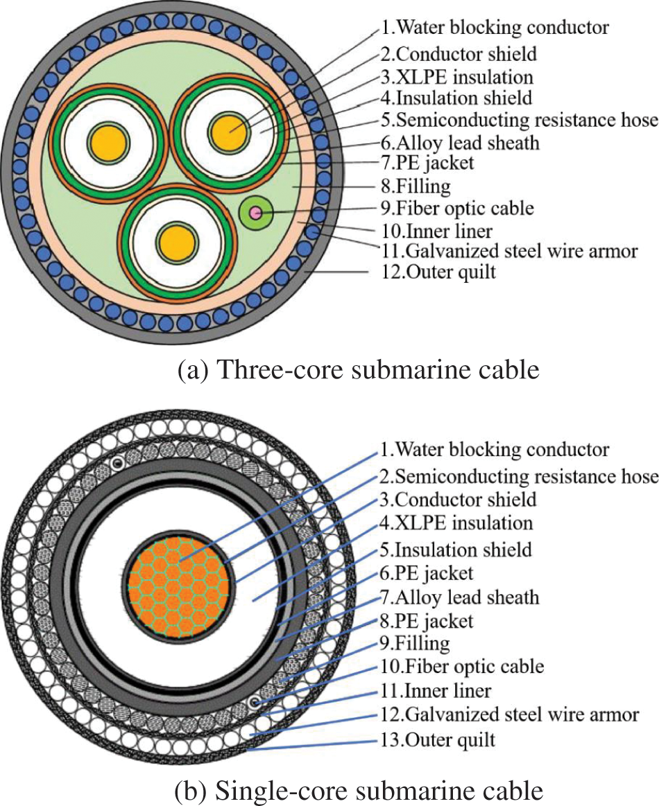
Figure 1: Structure diagram of submarine cable
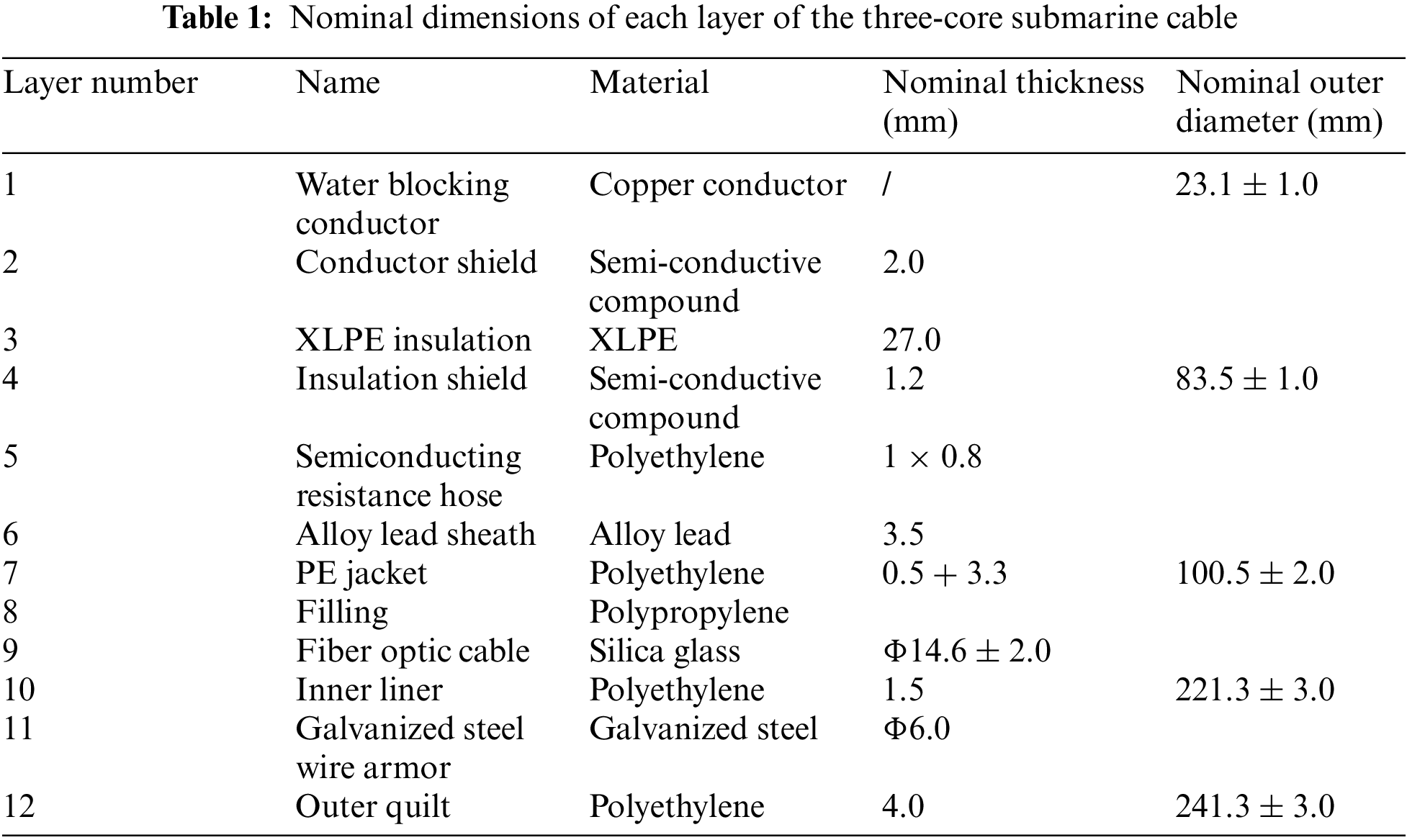
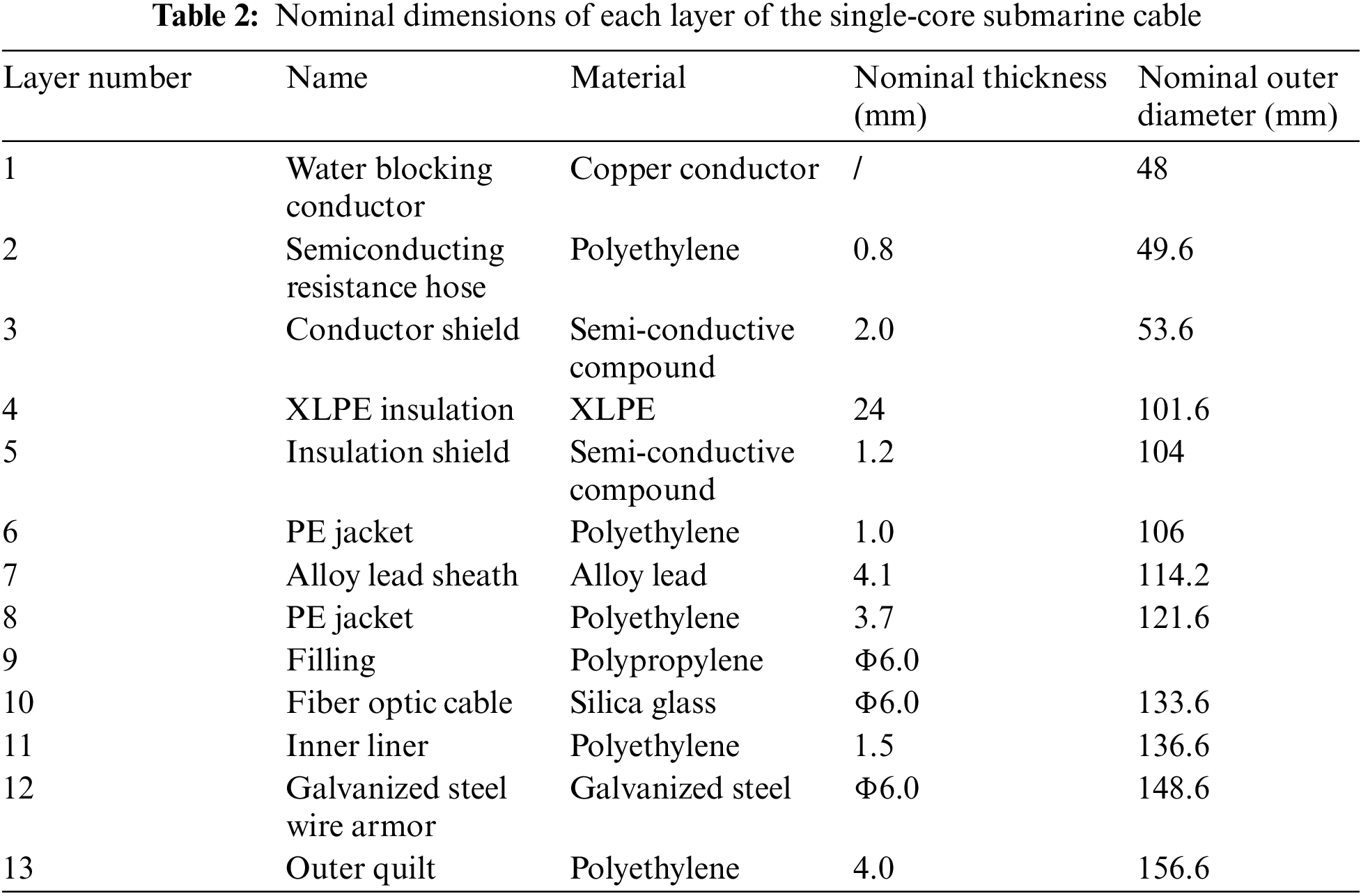
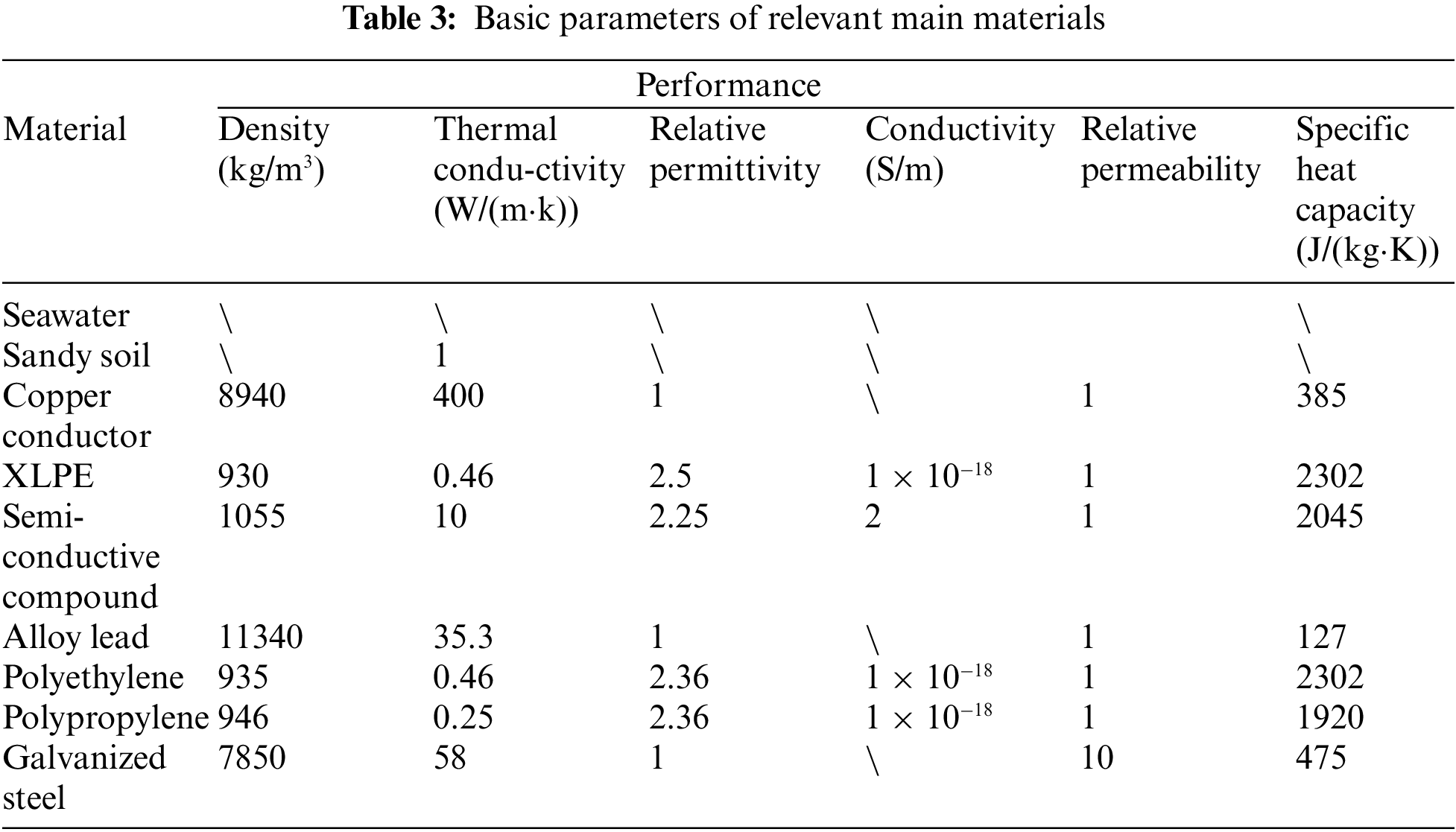
In this paper, the standard XLPE HVAC three-core and single-core submarine cable are selected, and the phase voltage is 220 kV. Its structure is composed of shielding layer and copper cable core. The three cable cores are arranged in triangle for the three-core photoelectric composite submarine cable. The core of the optical unit beside the cable core is optical fiber. By observing the cable core, it can be found that its interior is composed of many copper wires, which are twisted together and coated and filled with semiconductor mixture and cross-linked polyethylene (XPLE) from the inside to the outside [14,21,22]. The method proposed in this paper is not limited to the use of XLPE for the insulation layer. When other materials are used for the insulation layer, only the corresponding material parameters and the thickness of the insulation layer need to be replaced. At 20°C, the DC resistance of main conductor, lead sheath and armor layer of each phase is 3.3557 × 10⁻⁵ Ω/m, 2.9967 × 10⁻⁴ Ω/m and 2.4814 × 10⁻⁵ Ω/m, respectively. Tables 1 and 2 show the relevant information of the submarine cable structure. The basic parameters of the main materials in the photoelectric composite submarine cable are shown in Table 3.
3.2 Analysis of Electromagnetic Loss of Submarine Cable
The electric-magnetic-thermal coupled finite element analysis of the submarine cable model is carried out by using the mathematical physics model established in this paper. The electromagnetic loss analysis is carried out with the aid of the finite element analysis software COMSOL and MATLAB. In terms of boundary condition, it can be set according to the actual submarine cable laying situation and the verified cable analysis finite element model. The soil temperature far from the submarine cable is not affected by the submarine cable, so the temperature is fixed and belongs to the first boundary condition. This paper assumes that the submarine cable is completely laid in the seabed, and the temperature of the seabed is 20°C. The soil close to the submarine cable is affected by the temperature of the submarine cable, its heat flux density is
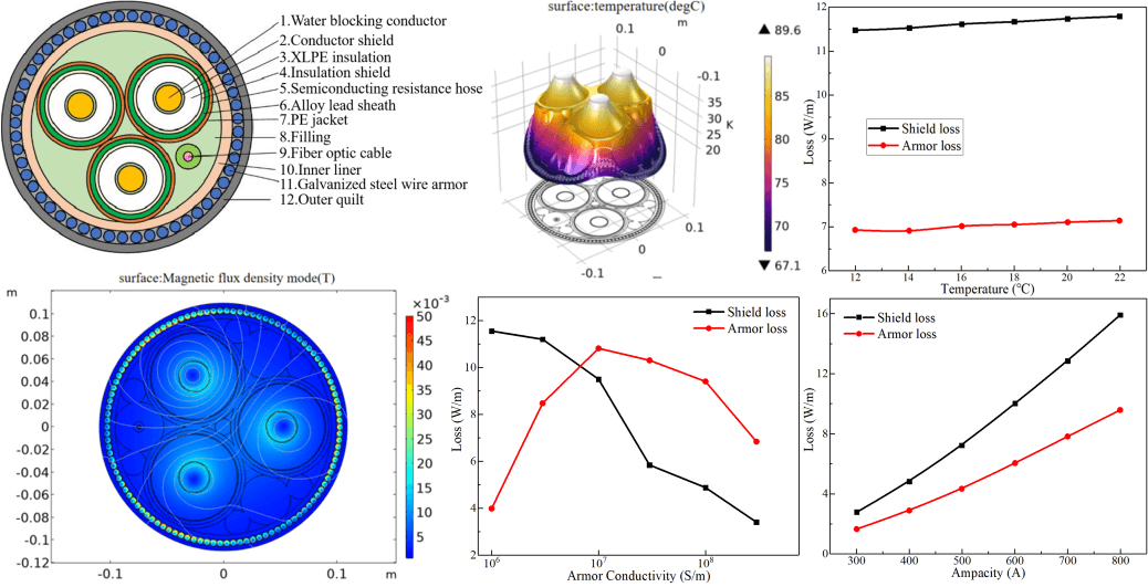
Taking out-of-plane current and magnetic flux as the research content, the photoelectric composite submarine cable is studied on the basis of frequency domain. Fig. 2 shows the specific situation of the magnetic flux density mode. The magnetic flux density mode is centrosymmetric, and the highest magnetic field strength exists in its conductor shielding layer.
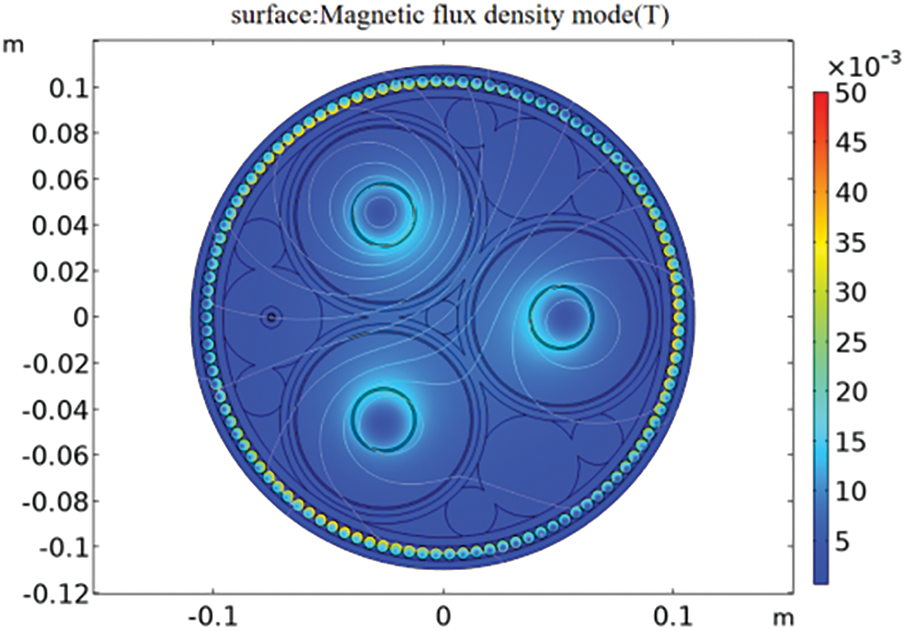
Figure 2: Magnetic flux density mode
It can be known from Maxwell’s equation that when the alternative current transmitted by the submarine cable causes the change of the surrounding magnetic field, electromagnetic loss will occur, which will cause energy loss to the submarine cable. Fig. 3 shows the specific situation of the out-of-plane current. The induced current is formed in the lead sheath and the armor layer, and its distance from the edge of the structure is inversely proportional to the current. In fact, there is also an induced current in the armor layer, but compared to the lead sheath, the induced current is not much here, so it cannot be represented in Fig. 3. The certain losses will be formed when transmitting electrical energy by means of submarine cables. In addition to the electromagnetic losses of the cable core and the lead sheath, electromagnetic losses will also occur in the armor layer.
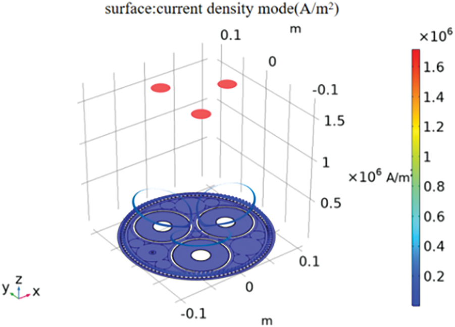
Figure 3: Current density mode
To quantitatively analyze the specific situation of the optoelectronic composite cable, it is necessary to analyze its volume loss (the cable core is not included), as shown in Fig. 4. Without considering the cable core, most of the loss comes from the lead sheath. By using the integral operation to process the volume loss of each structure, the loss of three layers of the submarine cable can be clarified. The armor layer and lead sheath are 9.87 and 17.19 kW/km, respectively, while the cable core is 48.19 kW/km. This paper mainly analyzes the characteristics of loss caused by electromagnetic induction, which is mainly the loss of shielding layer (lead sheath) and armor layer caused by inductive effect.
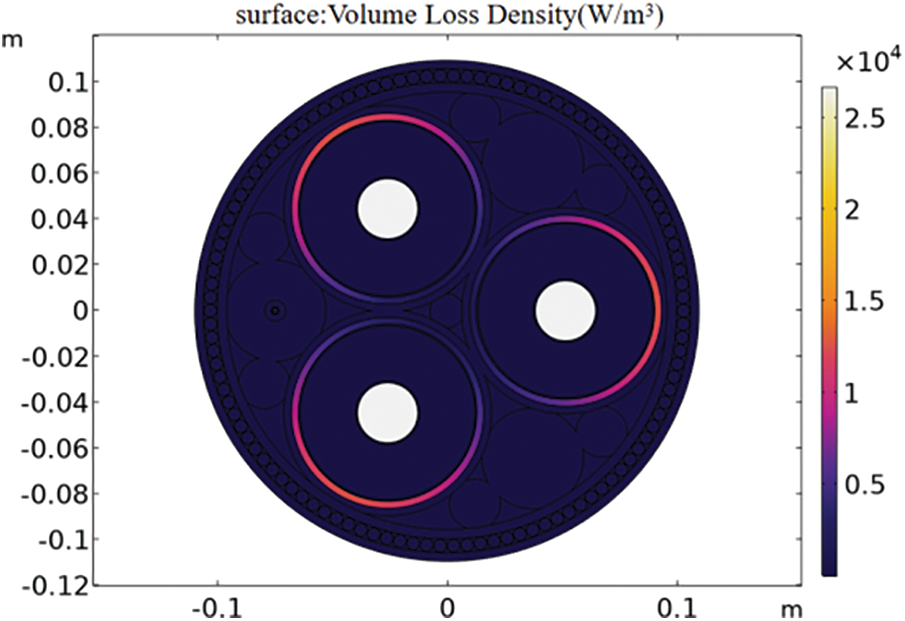
Figure 4: Volume loss density
4 Analysis of Factors Influencing Electromagnetic Loss of Submarine Cable
The cost of submarine cables is very expensive, and the working environment is complex and changeable, so it is difficult and costly to conduct test. The finite element analysis method is used to effectively and accurately analyze the complex engineering problems. By establishing an accurate analysis model of the multi-physical field coupling of submarine cables, the interrelationship between the key physical quantities in the submarine cable operation system is explored, and the electromagnetic loss of submarine cables in different environmental temperatures, ampacity and material properties of armor layer is analyzed.
4.1 Influence of Ambient Temperature on Electromagnetic Loss of Submarine Cable
When the three-phase submarine cable operates normally at the rated current of 660 A, the temperature distribution of each layer of the submarine cable is shown in Fig. 5.
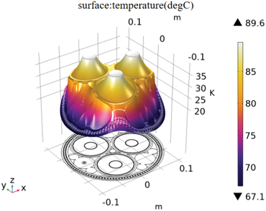
Figure 5: Operating temperature of submarine cable
For the sea environment, the temperature of seawater is different in different seasons, and the temperature of the marine soil is also quite different. The convective heat transfer coefficient between seawater and soil is also closely related to the season. Observing the laying environment ofthe submarine cable, it is found that the seawater temperature will be affected by seasonal changes. The lowest temperature is not less than 10°C and the highest temperature is not more than 23°C [23]. The seawater temperature of 12°C, 14°C, 16°C, 18°C, 20°C and 22°C are selected to calculate the shielding layer loss and armor loss, and the results are shown in Fig. 6.
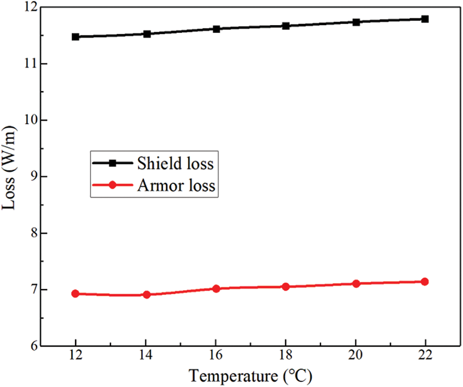
Figure 6: The loss of the shielding layer and armor layer at different temperatures
It can be seen from the analysis of Fig. 6 that the shielding layer loss and armor loss increase slightly with the increase of external temperature. When the temperature is 12°C, the shielding layer loss is 11.5 W/m, and the armor loss is 6.95 W/m. When the temperature rises to 22°C, the shielding layer loss is 11.8 W/m, and the armor loss is 7.05 W/m, so the actual ambient temperature has little effect on the loss.
4.2 Influence of Current Carrying Capacity on Electromagnetic Loss of Submarine Cable
During the operation of the offshore wind farms, the power generation efficiency of wind farms and the current carrying capacity of submarine cables will change with the change of seasonal climate. By analyzing the operation status of submarine cables, 300 to 900 A is selected as the simulated ampacity to study the loss of shielding layer and armor layer under different ampacity. The results are shown in Fig. 7. When the ampacity is 300 A, the shielding layer loss is 2.8 W/m, and the armoring layer loss is 1.8 W/m. When the current carrying capacity rises to 800 A, the shielding layer loss is 16.7 W/m, and the armor layer loss is 9.2 W/m. The loss of shielding layer and armor layer increases with the increase of current carrying capacity, and the ampacity has a greater impact on the loss of shielding layer.
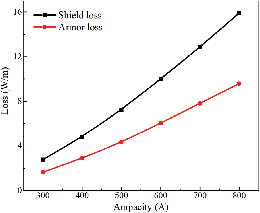
Figure 7: Effect of ampacity on submarine cable loss
4.3 Influence of Armor Conductivity and Permeability and Laying Spacing on Electromagnetic Loss of Submarine Cable
In practical applications, the conductivity and relative permeability of the armor layer of submarine cables are not only affected by the category of the material itself, but also by factors such as temperature. It is the most changeable material attribute parameter among the parameters of each metal layer of the submarine cable. Therefore, this paper studies the influence of the conductivity and relative permeability of the armor layer on the electromagnetic loss of the submarine cable. The rated current is 600 A. The results calculated by the method in this paper are shown in Figs. 8–11.
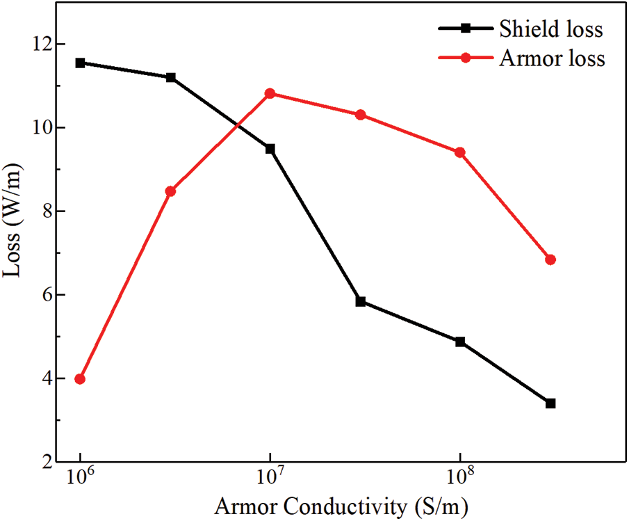
Figure 8: Effect of conductivity of armor layer on single-core submarine cable loss
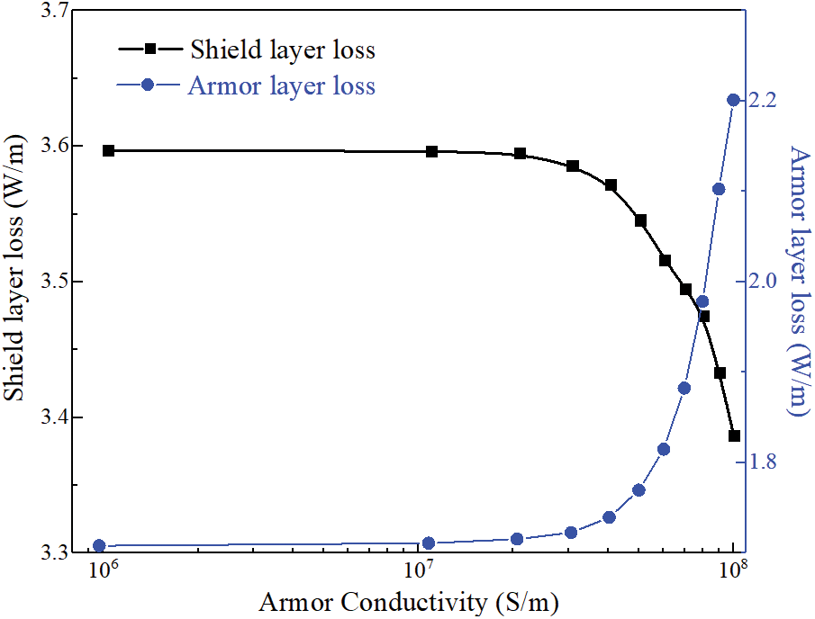
Figure 9: Effect of conductivity of armor layer on three-core submarine cable loss
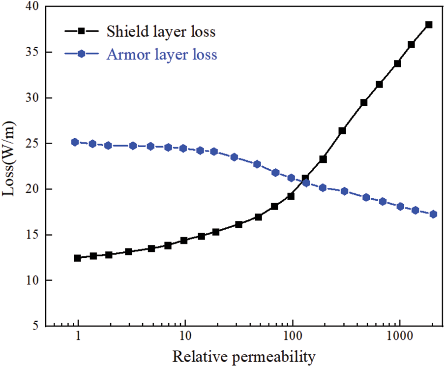
Figure 10: Effect of relative permeability of armor layer on single-core submarine cable loss
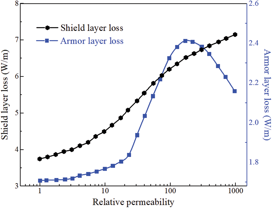
Figure 11: Effect of relative permeability of armor layer on three-core submarine cable loss
It can be seen from Fig. 8 that the loss of the armor layer itself shows a trend of rising first and then falling whose maximum value appears at 1 × 10⁷ S/m with the increase of the conductivity of the armor layer for single-core submarine cables. The loss of the shielding layer decreases with the increase of the conductivity of the armor layer. The rate of decline increases first and then decreases, and the inflection point also appears near 1 × 10⁷ S/m. Although the loss of armor layer increases first and then decreases with its conductivity, the current of armor layer has been increasing with the increase of its conductivity. Therefore, the shielding effect of armor layer on other metal layers has been increasing, so the loss of other metal layers has a downward trend on the whole. At the same time, the conductivity of the metal materials used in the armor layer is generally greater than 1 × 10⁷ S/m, therefore, the armor layer should be made of materials with high conductivity for single-core submarine cables.
It can be seen from Fig. 9 that the loss of shielding layer will decrease with the increase of the conductivity of the armor layer and the loss of the armor layer itself will increase with the increase of its own conductivity for three-core submarine cables. However, due to the existence of torsional offset effect, there is only a small amount of eddy current and no obvious circulation in the armor layer, and the loss ratio is very small. Thus, its actual impact on the overall cable loss is not large and can be almost ignored. Therefore, the materials with high conductivity can be used to reduce the overall electromagnetic loss when the tensile strength of the armor layer meets the requirements for three-core submarine cables.
Through the analysis of Fig. 10, it is found that the loss of the shield layer increases with the increase of the relative permeability of the armor layer for single-core submarine cables, which also proves from the data point of view that the increase of magnetic flux density will lead to the increase of submarine cable loss. While the relative permeability of the armor layer increases, its electromagnetic loss decreases, but the decrease is small. The reason for this phenomenon is that the magnetic flux and circular current of the shielding layer increase with the increase of the magnetic permeability of the armor layer, and the shielding effect is enhanced. However, the strengthening effect of the conductor tape under the current structure is significantly weaker than the shielding effect of the other two metal layers, so the loss of the armored layer is reduced. To sum up, materials with low relative permeability should be selected as far as possible for single-core submarine cables.
The curve of the influence of the relative permeability of the three-core submarine cable armor layer on the loss (Fig. 11) revealed that the loss of the armor layer itself rises first and then decreases while the loss of the shield layer has always shown an upward trend with the increase of the relative permeability of the armor layer. However, the loss of the armor layer itself is smaller compared with the loss of shield layer. Therefore, the material with low relative permeability can be used for the three-core submarine cable to reduce the electromagnetic loss.
Studying the adjustable parameters in laying such as laying spacing will help to explore the reasonable laying method, that is, reducing the space occupied by laying and the difficulty of laying while reducing the loss and taking into account the heat dissipation. Fig. 12 shows the curve of the electromagnetic loss of each metal structure in the wire-steel armored single-core submarine cable varying with the laying distance.
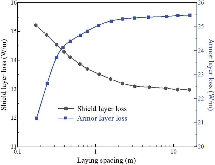
Figure 12: Effect of submarine cable laying spacing on single-core submarine cable loss
It can be seen from Fig. 12 that only the total loss of the armor layer shows an upward trend while the shield layer shows a downward trend with the increase of the laying distance. By adding the sum of the two losses, it can be found that although the electromagnetic loss of each layer of metal structure has changed with the change of the laying distance, the total change is not obvious, only showing a weak trend of increasing first and then decreasing. In terms of the influence of laying distance on cable electromagnetic loss, three-core submarine cable has the same trend as single-core submarine cable.
In this paper, the loss of each layer of the submarine cable is studied through the multi-physical field coupling modeling of the photoelectric composite submarine cable. By changing the ambient temperature, ampacity and material properties of armor layer, the change of the loss of the shielding layer and the armor layer is analyzed, and the conclusions are as follows:
(1) During the operation of the submarine cable, the ambient temperature will have a certain impact on the overall temperature of the submarine cable. However, the loss of shielding layer and armor layer will increase slightly with the increase of external temperature, so it can be ignored.
(2) With the increase of the ampacity, the loss of the shielding layer and the armor layer of the submarine cable increase linearly. It can be seen that the electromagnetic loss of the submarine cable is closely related to the size of the ampacity.
(3) For single-core submarine cables, increasing the conductivity of the armor layer will make the loss of the armor layer itself increase first and then decrease. However, increasing the conductivity of the armor layer will reduce the total loss of all metal layers from the perspective of the overall electromagnetic loss and temperature rise of all metal layers, thus lowering the maximum temperature of the insulation layer and improving the current carrying capacity of the submarine cable. However, the rise of the conductivity of the armor layer cannot make its own loss reach the inflection point of decline for three-core submarine cables within the range of common material conductivity. Therefore, reducing the conductivity of the armor layer for three-core submarine cables can reduce the total loss of the metal layer, thereby reducing the maximum temperature of the insulation layer and improving the current carrying capacity of the submarine cable. Therefore, when the tensile strength of the armor layer meets the requirements, materials with high conductivity can be used to reduce the armor layer loss for single-core submarine cables.
(4) For single-core submarine cables, the higher relative permeability of the armor layer will reduce the loss of the armor layer itself, but the loss of the shield layer is increased due to the enhanced magnetic field, which improves the loss of the submarine cable as a whole and reduces the current carrying capacity of the submarine cable. For three-core submarine cables, the influence of the relative permeability of the armor layer on the loss of the armor layer is not very obvious, and the loss of the shield layer will rise with the increase of the relative permeability of the armor layer. For three-core submarine cables, materials with low relative permeability can be used to reduce losses.
(5) For submarine cables, the loss of each metal layer of the submarine cable under horizontal laying increases with the increase of laying spacing. However, due to the better heat dissipation conditions, increasing the laying spacing will increase the loss, but it can improve the overall current carrying capacity of the submarine cable.
Acknowledgement: The authors acknowledge the reviewers for providing valuable comments and helpful suggestions to improve the manuscript.
Funding Statement: This work was supported in part by the Science and Technology Projects of China Southern Power Grid Corporation (037700KK52220011), the China Postdoctoral Science Foundation (2019M653631), Key R&D Plan of Shaanxi (2021GY-320, 2021GY-306, 2020ZDLGY09-10), Xi’an Science and Technology Project (22GXFW0039), and the Innovation Capability Support Program of Shaanxi Province (Program No. 2022KJXX-41).
Author Contributions: The authors confirm contribution to the paper as follows: study conception and design: Liuhuo Wang, Yi Tian; data collection: Long Zhao; analysis and interpretation of results: Wenwei Zhu, Yanru Wang, Liuhuo Wang; draft manuscript preparation: Liuhuo Wang, Qingcui Liu. All authors reviewed the results and approved the final version of the manuscript.
Availability of Data and Materials: The data underlying this article are available in the article.
Conflicts of Interest: The authors declare that they have no conflicts of interest to report regarding the present study.
References
1. Worzyk, T. (2009). Submarine power cables: Design, installation, repair, environmental aspects. USA: Springer Science & Business Media. [Google Scholar]
2. Anders, G. J. (2005). Institute of electrical and electronics engineers. Rating of electric power cables in unfavorable thermal environment. USA: Wiley. [Google Scholar]
3. Xie, Y., Wang, C., Huang, J. (2022). Structure and evolution of the submarine cable network of Chinese mainland. Journal of Geographical Sciences, 32(5), 932–956. [Google Scholar]
4. Li, H., Yu, P., Li, S., Deng, J. (2022). Study on internal overvoltages of 220 kV submarine cable transmission system of the offshore oil–gas field group. Energy Reports, 8, 377–386. [Google Scholar]
5. Taormina, B., Bald, J., Want, A., Thouzeau, G., Lejart, M. et al. (2018). A review of potential impacts of submarine power cables on the marine environment: Knowledge gaps, recommendations and future directions. Renewable and Sustainable Energy Reviews, 96, 380–391. [Google Scholar]
6. Marra, G., Fairweather, D., Kamalov, V., Gaynor, P., Cantono, M. et al. (2022). Optical interferometry-based array of seafloor environmental sensors using a transoceanic submarine cable. Science, 376(6595), 874–879 [Google Scholar] [PubMed]
7. Lu, J., Qin, Q., Tan, C., Li, B., Fan, X. (2021). Loss analysis of electromagnetic linear actuator coupling control electromagnetic mechanical system. Energy Engineering, 118(6), 1741–1754. https://doi.org/10.32604/EE.2021.014977 [Google Scholar] [CrossRef]
8. Marty, A., Berhault, C., Damblans, G., Facq, J., Gaurier, B. et al. (2021). Experimental study of hard marine growth effect on the hydrodynamical behaviour of a submarine cable. Applied Ocean Research, 114, 102810. [Google Scholar]
9. Chen, J., Zhang, W., Ding, M., Hu, L., Wang, J. et al. (2021). Aging characteristics of XLPE insulation of 110 kV cables in the initial stage of operation. Energy Engineering, 118(5), 1537–1548. https://doi.org/10.32604/EE.2021.015439 [Google Scholar] [CrossRef]
10. Jiang, Z., Dong, S., Zhang, Y., Liu, G., Dong, T. (2021). Corrosion of copper armor caused by induced current in a 500 kV alternating current submarine cable. Electric Power Systems Research, 195, 107144. [Google Scholar]
11. Lin, Y., Li, Z., Hao, Y. (2016). Calculation of current-carrying capacity of HVDC cable joint under constraints of operating temperature and temperature difference of insulating layer. Automation of Electric Power System, 40(18), 129–134. [Google Scholar]
12. Du, B., Kong, X., Cui, B., Li, J. (2017). Improved ampacity of buried HVDC cable with high thermal conductivity LDPE/BN insulation. IEEE Transactions on Dielectrics and Electrical Insulation, 24(5), 2667–2676. [Google Scholar]
13. Hvidsten, S., Kvande, S., Ryen, A., Larsen, P. (2009). Severe degradation of the conductor screen of service and laboratory aged medium voltage XLPE insulated cables. IEEE Transactions on Dielectrics and Electrical Insulation, 16(1), 155–161. [Google Scholar]
14. Dai, X., Hao, J., Liao, R., Zheng, X., Gao, Z. et al. (2021). Multi-dimensional analysis and correlation mechanism of thermal degradation characteristics of XLPE insulation for extra high voltage submarine cable. IEEE Transactions on Dielectrics and Electrical Insulation, 28(5), 1488–1496. [Google Scholar]
15. Hughes, T., Henstock, T., Pilgrim, J., Dix, J., Gernon, T. et al. (2015). Effect of sediment properties on the thermal performance of submarine HV cables. IEEE Transactions on Power Delivery, 30(6), 2443–2450. [Google Scholar]
16. Hatlo, M., Bremnes, J. J. (2014). Current dependent armour loss in three-core cables: Comparison of FEA results and measurements. Proceedings of the CIGRÉ Session, pp. 24–29. Paris, France. [Google Scholar]
17. Giussani, L., di Rienzo, L., Bechis, M., Falco, C. (2021). Fully coupled computation of losses in metallic sheaths and armor of AC submarine cables. IEEE Transactions on Power Delivery, 37(5), 3803–3812. [Google Scholar]
18. Zhang, Z., Zhao, J., Zhao, W., Zhong, L., Hu, L. et al. (2020). Influence of morphological variations on the AC breakdown of XLPE insulation in submarine cable factory joints. High Voltage, 5(1), 69–75. [Google Scholar]
19. Garrido, C., Otero, A., Cidras, J. (2003). Theoretical model to calculate steady-state and transient ampacity and temperature in buried cables. IEEE Transactions on Power Delivery, 18(3), 667–678. [Google Scholar]
20. Ocłoń, P., Cisek, P., Pilarczyk, M., Taler, D. (2015). Numerical simulation of heat dissipation processes in underground power cable system situated in thermal backfill and buried in a multilayered soil. Energy Conversion and Management, 95, 352–370. [Google Scholar]
21. Xu, Z., Hu, Z., Zhao, L., Zhang, Y., Yang, Z. et al. (2019). Application of temperature field modeling in monitoring of optic-electric composite submarine cable with insulation degradation. Measurement, 133, 479–494. [Google Scholar]
22. Giussani, L., Rienzo, L., Bechis, M., Falco, C. (2020). Computation of armor losses in AC submarine cables. IEEE Transactions on Power Delivery, 36(5), 3014–3021. [Google Scholar]
23. Song, H., Wignall, P., Song, H., Dai, X., Chu, D. (2019). Seawater temperature and dissolved oxygen over the past 500 million years. Journal of Earth Science, 30, 236–243. [Google Scholar]
Cite This Article
 Copyright © 2023 The Author(s). Published by Tech Science Press.
This work is licensed under a Creative Commons Attribution 4.0 International License , which permits unrestricted use, distribution, and reproduction in any medium, provided the original work is properly cited.
 Downloads
 Citation Tools