
 Submit a Paper
 Propose a Special lssue
 Open Access
ARTICLE

Optimization of DC Resistance Divider Up to 1200 kV Using Thermal and Electric Field Analysis
Department of Metrology, China Electric Power Research Institute, Wuhan, 430074, China
* Corresponding Author: Jicheng Yu. Email:
(This article belongs to the Special Issue: Fault Diagnosis and State Evaluation of New Power Grid)
Energy Engineering 2023, 120(11), 2611-2628. https://doi.org/10.32604/ee.2023.028282
Received 12 December 2022; Accepted 29 March 2023; Issue published 31 October 2023
 View Full Text
 Download PDF
Abstract
Self-heating and electric field distribution are the primary factors affecting the accuracy of the Ultra High Voltage Direct Current (UHVDC) resistive divider. Reducing the internal temperature rise of the voltage divider caused by self-heating, reducing the maximum electric field strength of the voltage divider, and uniform electric field distribution can effectively improve the UHVDC resistive divider’s accuracy. In this paper, thermal analysis and electric field distribution optimization design of 1200 kV UHVDC resistive divider are carried out: (1) Using the proposed iterative algorithm, the heat dissipation and temperature distribution of the high voltage DC resistive divider are studied, and the influence of the ambient temperature and the power of the divider on the temperature of the insulating medium of the divider is analyzed; (2) Established the finite element models of 1200 kV and 2 × 600 kV DC resistive dividers, analyzed the influence of the size of the grading ring and the installation position on the maximum electric field strength of the voltage divider, and calculated the impact of the shielding resistor layer on the vicinity of the measuring resistor layer. The research indicates that: (1) The temperature of the insulating medium is linearly related to the horsepower of the voltage divider and the ambient temperature; (2) After the optimized design of the electric field, the maximum electric field strength of the 1200 kV DC resistive divider is reduced to 1471 V/mm, which is about 24% lower than that of the unoptimized design; (3) Installing the shielding resistor layer can significantly improve the electric field near the measuring resistor layer. This paper has an important reference function for improving the accuracy of the UHVDC resistive divider.Keywords
High voltage direct current (HVDC) transmission is advanced in large capacity and long-distance power transmission [1,2]. By 2022, about twenty ±800 kV and one ±1100 kV HVDC projects will be under commercial operation in China [3–5]. Accurately measuring DC voltage is essential for power utilization and effective control of HVDC transmission systems. However, since the voltage of the UHVDC system can reach up to 1200 kV, it will cause a complex electromagnetic environment, making it difficult to measure the voltage accurately [6].
The resistive divider is the most accurate device for measuring UHVDC voltage [7]. The resistive divider is widely applied in voltage measurements of 100 kV and higher [8–10]. The accuracy of the UHVDC resistive divider has many influencing factors, especially with a high-rated voltage [11]. When the UHVDC resistive divider works at rated voltage, its power loss is extensive due to the self-heating effect is significant. When the temperature inside the divider keeps rising, it will not only change the divider’s voltage ratio but also causes thermal damage to the internal components of the divider, thus, shortening the service life of the divider and even inducing severe cases [12–14].
As the voltage level increases, the influence of corona current and leakage current on the resistive divider becomes increasingly apparent [15,16]. When designing a standard DC resistive divider above 600 kV, it is necessary to consider reducing the maximum electric field strength to ensure insulation and to make the electric field distribution near the measuring resistor layer uniform to reduce the impact of corona current and leakage current on the accuracy of the divider [17,18]. Therefore, the research and analysis of the heat dissipation and temperature distribution of the resistive divider is helpful for the selecting of components and the optimization of the heat dissipation structure in the design of the voltage divider and also helps to evaluate the safety and reliability of the voltage divider.
Research on high-precision DC resistive dividers mainly focuses on numerical traceability methods and calibration techniques, such as traceability of proportional values at low voltages and calibration of voltage coefficients at the low voltage expands to the high voltage. At present, the highest voltage level of the voltage divider is 1000 kV, and the rated voltage of most voltage dividers is 300 kV and below. There are few studies on the optimal design of high-precision DC resistive dividers for voltage classes up to 1200 kV. This paper studies the design and manufacture of a 1200 kV high-precision DC resistive divider. The HVDC resistive divider’s thermal analysis and electric field design are studied. First, to control the effect of temperature rise on the measurement performance of the voltage divider, an iterative algorithm for calculating the heat dissipation and temperature distribution of the resistive voltage divider is proposed. Then the influence of ambient temperature and voltage divider power on the temperature of the insulation medium of the voltage divider is studied. In addition, the finite element model of the high voltage DC resistive divider is established, and the 1200 kV and 2 × 600 kV dividers are given. The electric field simulation is carried out. The influence of the size and installation position of the grading ring on the maximum electric field strength of the voltage divider is analyzed. Then the electric field distribution of the measuring resistor layer is calculated under various conditions.
2 Proposed Iterative Algorithm of Temperature Rise and Heat Dissipation
2.1 Resistive Divider’s Heat Transfer Process
Fig. 1 illustrates the typical configuration of a standard resistive divider and its corresponding heat transfer mechanism. In this schematic, the components are labeled as 1, 2, and 3, representing the metal cover plate, bottom plate, and insulating bushing, respectively. The inner wall temperatures of these components are denoted as
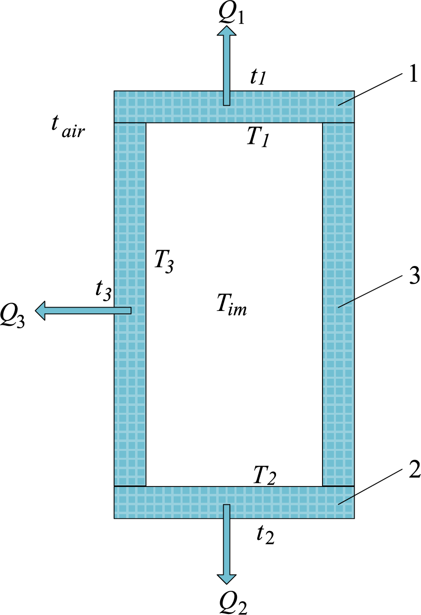
Figure 1: Structure of standard resistive divider and its heat transfer process
Following the principle of energy conservation, the heat produced by the resistor is eventually conveyed to the ambient air beyond the enclosure. Eq. (1) encapsulates this dynamic process of heat transfer.
where P is the consumed power and
2.2 Surface Heat Transfer Coefficient Calculation
In a standard voltage divider, the fluid serves as the insulating medium. The knowledge of the fluid temperature (
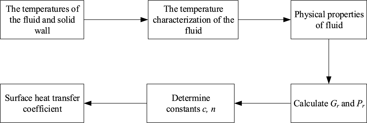
Figure 2: Flow chart for surface heat transfer coefficient calculation
The determination of the fluid’s qualitative temperature begins by acquiring the temperature values of the fluid and the solid wall. This qualitative temperature is expressed as the mean of
where
2.3 Calculation of Insulation Medium Temperature
Given the knowledge of the solid inner wall temperature and the thermal exchange
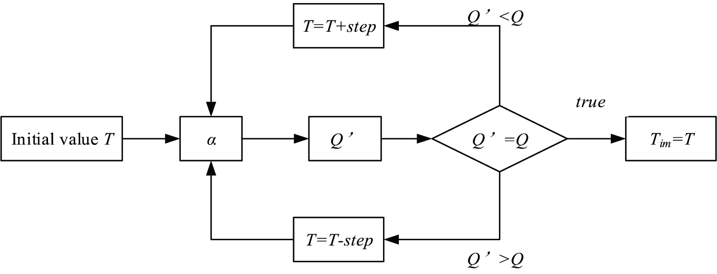
Figure 3: The calculation process of insulating medium temperature
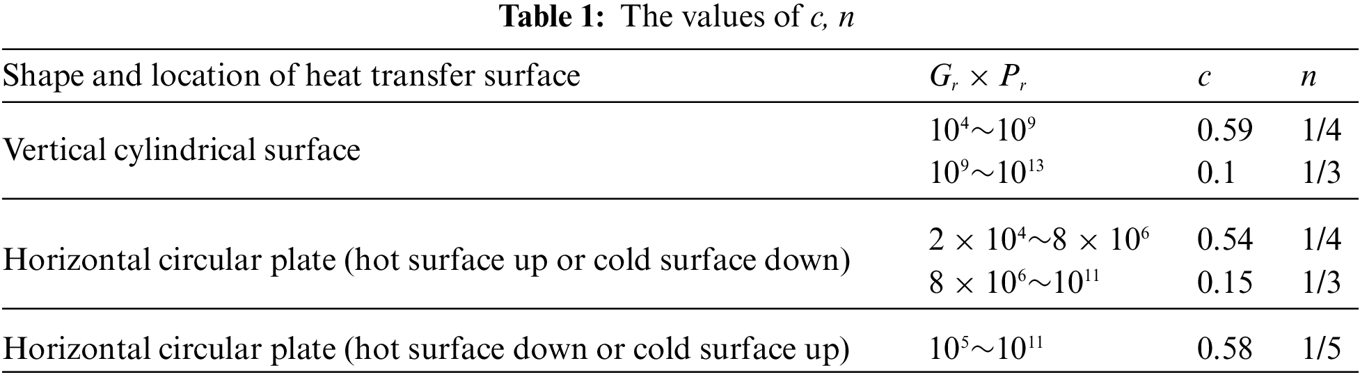
Firstly, the appropriate value
where
2.4 Calculation of Temperature and Heat Dissipation
When the standard divider reaches thermal equilibrium,
Step 1: The appropriate value
Step 2: The appropriate value
Step 3: The appropriate value
Step 4: If
3 Establishment of Electric Field Simulation Model
For the DC resistive standard voltage divider up to 1200 kV, its measuring resistor layer and shielding resistor layer are composed of many resistors in series, which are evenly distributed in a spiral shape around the insulating inner cylinder from the top to the bottom of the voltage divider, so it is not a strictly three-dimensional axisymmetric structure. In electric field analysis, it can be replaced by two cylinders with the same thickness and radius as the measuring resistor layer and the shielding resistor layer, and the potential distribution of the cylinders is the same as that of the resistor layer. After this treatment, the 1200 kV DC resistive standard divider is simplified to a three-dimensional axisymmetric structure without affecting the results of electric field analysis.
ANSYS uses Maxwell equations as the starting point for electromagnetic field analysis. According to the given boundary conditions and initial conditions, the finite element method is used to solve the degrees of freedom of each element node in the finite element model. When establishing the ANSYS finite element model of a three-dimensional axisymmetric structure, half of the spindle profile can be taken down to model in two-dimensional, so that the three-dimensional electrostatic field model can be transformed into a two-dimensional electrostatic field model. In the two-dimensional electrostatic field analysis, the degree of freedom of each element node is voltage [23,24].
The two-dimensional finite element analysis model of the 1200 kV resistive standard divider is shown in Fig. 4. With the high voltage conductive barrel, DC high voltage can be applied and connected with the shielding resistor layer and the measuring resistor layer. The inner insulating cylinder is plexiglass, and the outer insulating cylinder is an epoxy glass filament wound insulating cylinder, with no umbrella skirt outside and nitrogen filled inside. There are metal flanges at the bottom and top for easy installation. The heat-dissipating outer tube and cover plate are at the top of the outer insulating cylinder. The outer surface of the heat-dissipating outer tube and the inner surface of the cover plate are provided with annular radiators. The chassis is at the bottom of the outer insulating cylinder. The main and auxiliary grading rings are installed at the top of the divider.
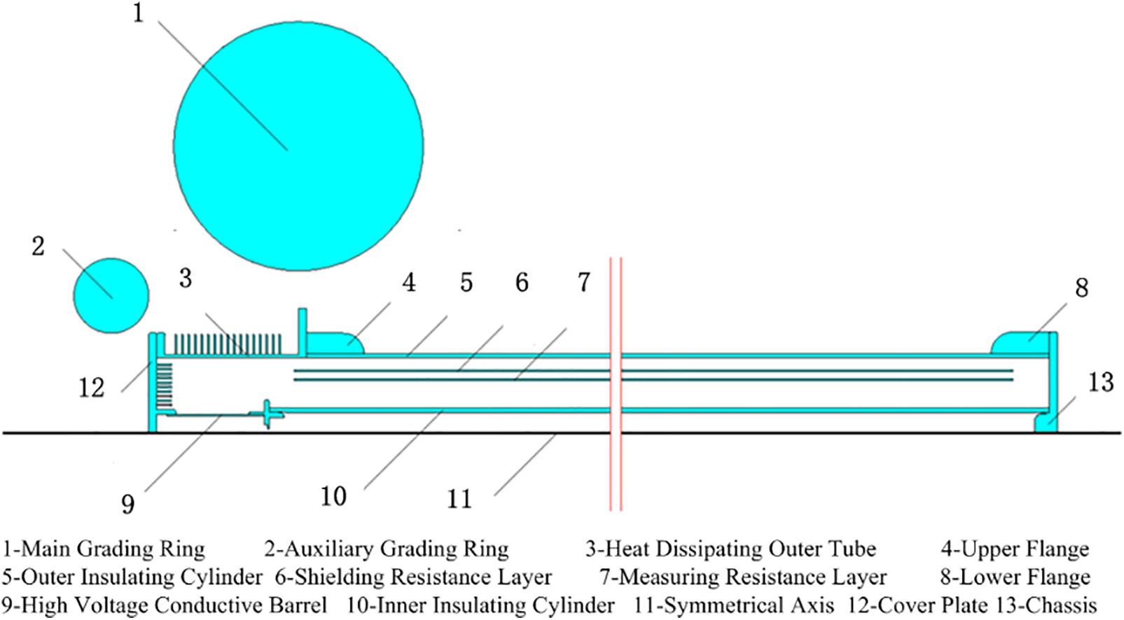
Figure 4: Model of the DC resistive standard divider up to 1200 kV
In addition, the design structure of 2 × 600 kV DC resistive standard divider was also presented in this paper, which was used to compare with the ordinary DC resistive standard divider rated 1200 kV. The design structure is shown in Fig. 5.
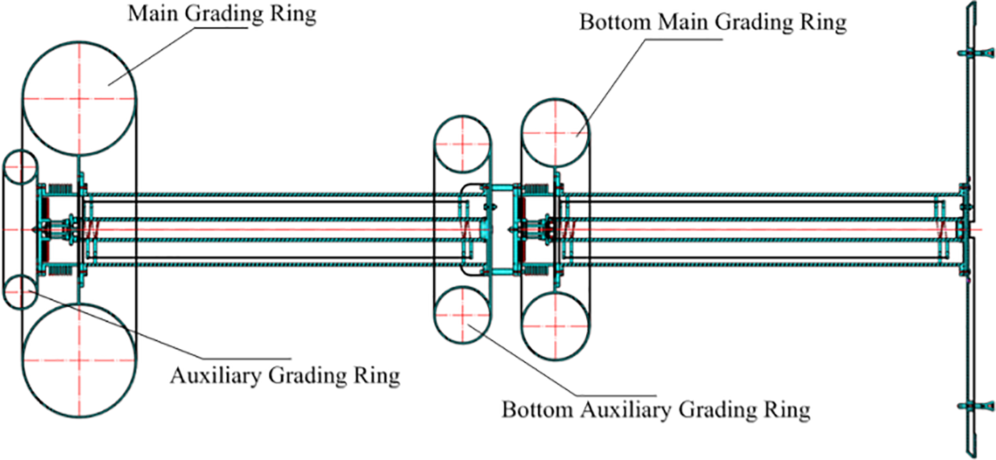
Figure 5: Diagram of 2 × 600 kV DC resistive standard divider
In electrostatic field analysis, the relative dielectric constant of metals is usually set to an immense value. The relative dielectric constant of metals is set to 106. In order to ensure that the potential of the shielding resistor layer and the measuring resistor layer decreases evenly from top to bottom, the relative dielectric constant of the shielding resistor layer should also be large enough, which is also set to 106. The relative dielectric constant of PMMA ranges from 3.9 to 4.1, and that of epoxy glass filament wound insulating cylinder ranges from 3 to 5. The median values are taken in this model, and the relative dielectric constant of the inner insulating cylinder and the outer insulating cylinder in the model is set to 4. The relative dielectric constant of air and nitrogen is set to 1 [25,26].
Using numerical calculation to set the analysis type as static, the maximum electric field strength and position of the DC resistive standard divider rated 1200 kV and the electric field distribution along the longitudinal direction of the measuring resistor layer can be obtained.
4 Calculation Results and Analysis
4.1 Result of Temperature Rise and Heat Dissipation
Table 2 is the typical size of the 1200 kV voltage divider. The insulating medium inside the divider is nitrogen and insulation oil. Under different air temperatures and different divider power, the divider of this typical size was calculated by an iterative algorithm. More concretely, given the power P consumed by the divider and the temperature

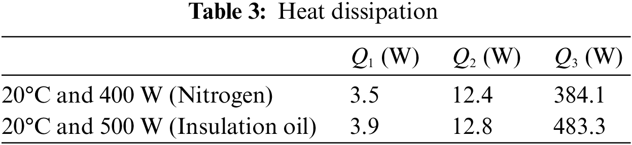
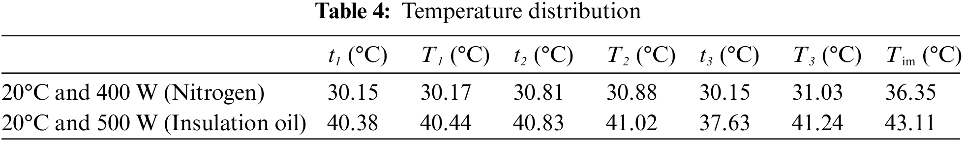
As can be seen from Table 3, for both nitrogen and insulation oil divider, since the heat dissipation area of the insulating bushing is much larger than that of the metal chassis and metal cover plate, most of the heat generated by the divider was transferred from the insulating bushing to the external air, accounting for about 96% of the total heat dissipation. Despite having the same material and size, the metal cover plate exhibits less than one-third of the heat dissipation observed in the metal chassis. This discrepancy arises due to the metal cover plate’s orientation, which promotes convective heat transfer as a horizontal circular plate with the heat-facing downwards, while the metal chassis experiences convective heat transfer as a horizontal circular plate with the heat-facing upwards. Table 4 reveals that the nitrogen temperature is 36.35°C and the insulation oil temperature is 43.11°C, resulting in temperature rises of 16.35°C and 23.11°C, respectively. Notably, the temperature difference between the inner and outer walls of the insulating bushing is considerably larger, measuring 0.88°C and 3.61°C, surpassing the temperature difference between the inner and outer walls of the metal cover plate and metal chassis. When the air temperature is 20°C and the divider power is different, the calculated insulating medium is shown in Fig. 6a, in which the abscissa is the divider power in W and the ordinate is the nitrogen temperature in °C. When the divider power is 400 W and the air temperature is different, the calculated insulating medium temperature is shown in Fig. 6b, in which the abscissa is the air temperature in °C, and the ordinate is the nitrogen temperature in °C.
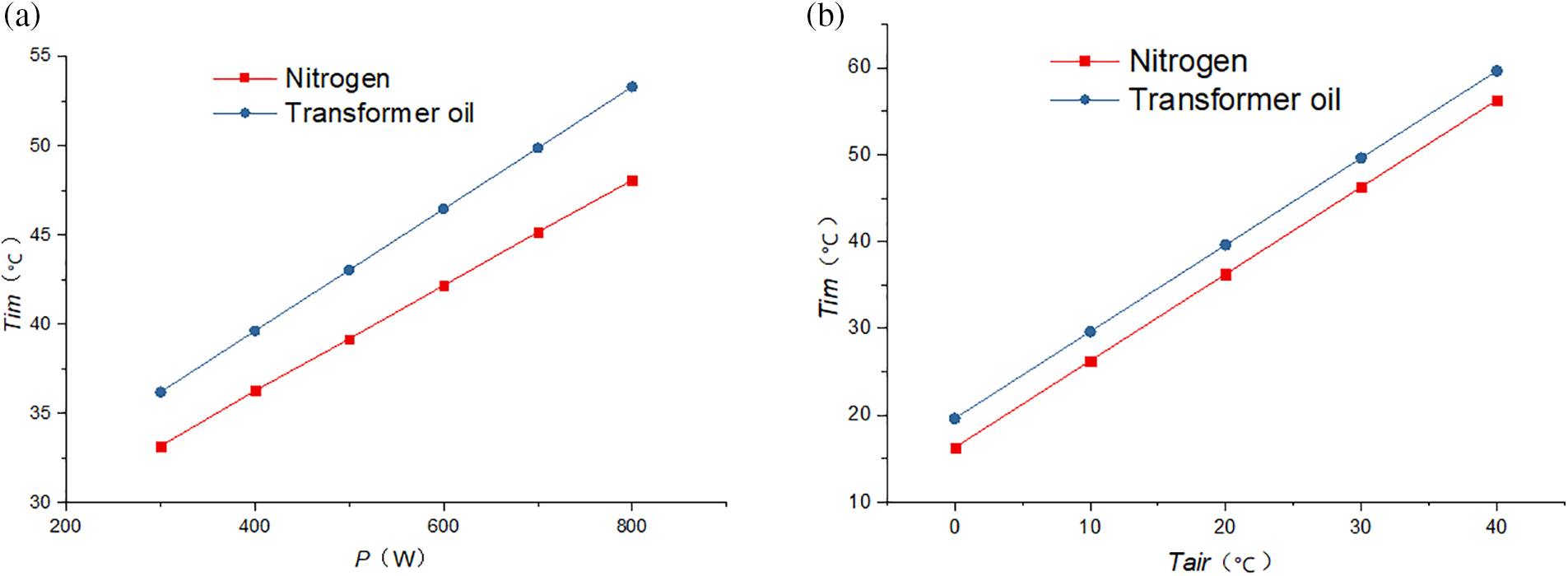
Figure 6: Insulating medium temperature. (a) at 20°C; (b) at 400 W
As depicted in Fig. 6, under constant external air temperature, there exists a linear correlation between the nitrogen temperature and the power output of the divider. The power of the divider increases from 300 to 800 W, and the temperature of nitrogen and insulation oil increases by about 3 and 3.42 degrees for every 100 W increase in power. From Fig. 6, it can be seen that when the power of the divider is constant, the temperature of the insulating medium and air also has a linear relationship. The temperature of the air rises from 0°C to 40°C and the temperature of both nitrogen and insulation oil rises about 10°C for every 10°C rise in air temperature.
For resistive dividers of this typical size, when nitrogen and insulation oil were used as insulating medium, the conclusions can be drawn from the above analysis.
(1) Most of the heat of the divider is transferred to the air through the insulating bushing.
(2) At an ambient temperature of 20°C and a divider power of 400 W, the nitrogen temperature within the divider reaches approximately 36°C upon achieving thermal equilibrium. Furthermore, with the air temperature remaining at 20°C and the divider power increasing to 500 W, the insulation oil temperature inside the divider reaches approximately 43°C once heat balance is attained.
(3) A linear relationship exists between insulating medium temperature, divider power and air temperature. For every 100 W increase of divider power, nitrogen and insulation oil temperature rises by about 3°C and 3.42°C, for every 10°C increase in air temperature, both nitrogen and insulation oil temperature rise by about 10°C.
(4) At the same ambient temperature and divider power, the temperature of insulating oil is slightly higher than that of nitrogen, about 3°C.
(5) If the developed 1200 kV voltage divider uses a similar size and nitrogen or insulation oil as an insulating medium, when the power does not exceed 400 W and the laboratory temperature is in the range of 20°C ± 5°C, the nitrogen temperature will rise to about 40°C which meets the ambient temperature requirements of the resistor.
4.2 Simulation Results of Maximum Electric Field
4.2.1 Effect of Grading Ring on Electric Field Near the Electrode
The electric field distribution of the DC resistive standard divider rated 1200 kV was calculated without installing the grading ring, only installing the main grading ring and installing the main grading ring and auxiliary grading ring. The simulation results are shown in Fig. 7.
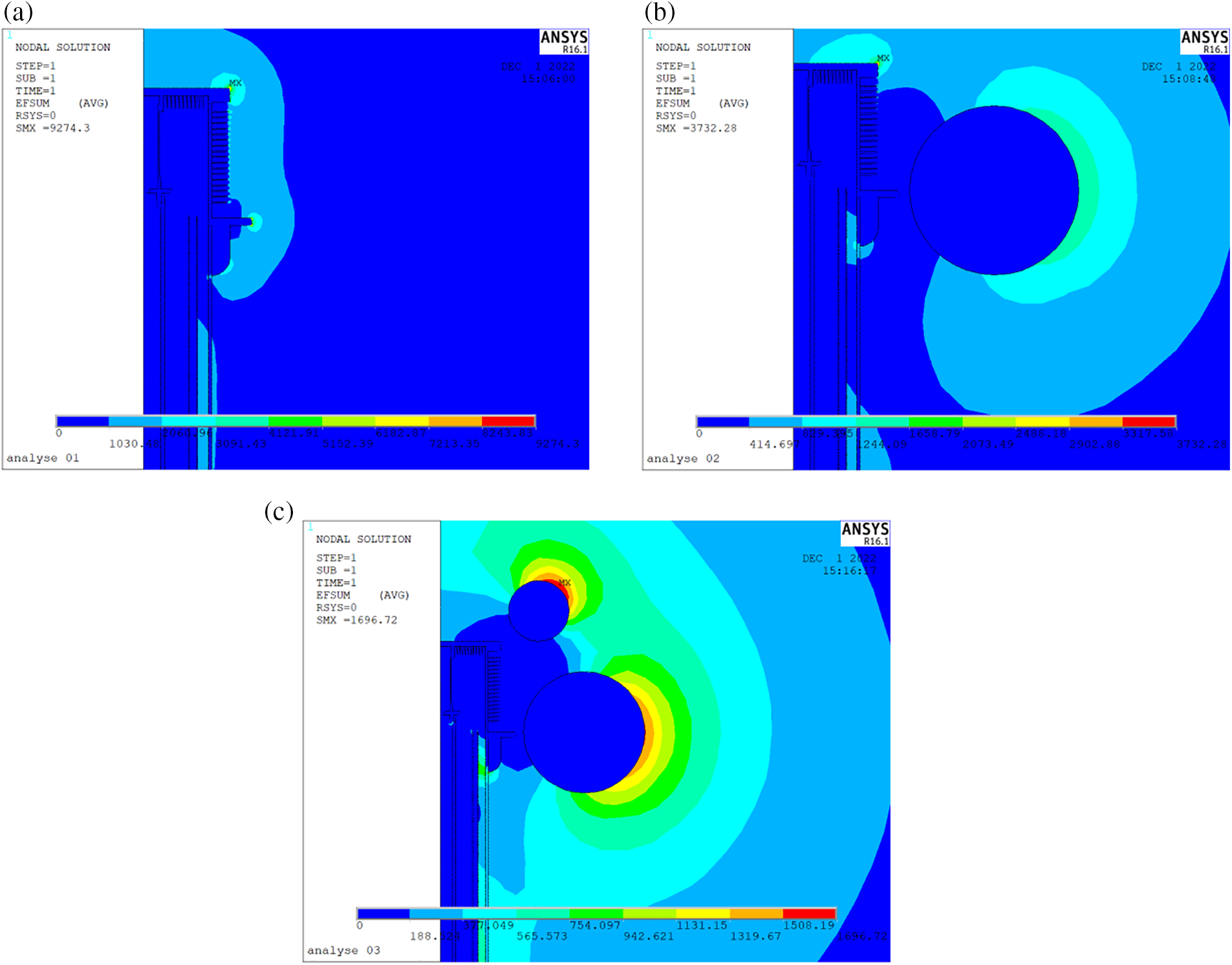
Figure 7: Electric field distribution of 1200 kV DC resistive standard divider. (a) Without installing grading ring; (b) Installing main grading ring; (c) Installing both main and auxiliary grading ring
Fig. 7a is the distribution of the electric field when the grading ring is not installed: the maximum electric field strength reaches 9274 V/mm, which is located at the end of the cover plate, the field strength at the end of the lower flange of the heat dissipating outer tube exceeds 8244 V/mm, and the field strength at the end of the upper flange and the end of the radiating fin of the heat dissipating outer tube exceeds 3091 V/mm. Fig. 7b shows the electric field distribution when only the main grading ring is installed: the maximum electric field strength is still at the end of the cover plate but drops to 3732 V/mm. The electric field strength at the end of the lower flange and the end of the lower radiator of the heat-dissipating outer tube is below 415 V/mm. However, the electric field strength at the end of the upper flange and the end of the upper radiator is still high, exceeding 1659 V/mm. Fig. 7c shows the electric field distribution when the main and auxiliary grading rings are installed: the maximum electric field strength decreases to 1697 V/mm, the position also shifts to the outer surface of the auxiliary grading rings, and the electric field strength of the cover plate and the heat dissipating outer tube decreases below 189 V/mm.
Adding a voltage grading ring can significantly improve the electric field distribution near the high-voltage electrode and reduce the maximum electric field strength. Due to the high height of the heat-dissipating outer tube, although the main grading ring can significantly improve the lower electric field, it has limited influence on the upper electric field of the cover plate and the heat-dissipating outer tube, and the auxiliary grading ring can further improve the electric field of the cover plate and the upper part. Therefore, developing a rated 1200 kV DC resistive standard voltage divider requires the installation of main and auxiliary voltage grading rings simultaneously.
This paper also simulates the electric field distribution of the 2 × 600 kV DC resistive standard voltage divider with or without auxiliary grading rings. The simulation results are shown in Fig. 8. It can be seen from the figure that the auxiliary grading ring of the 2 × 600 kV DC resistive standard voltage divider can also reduce the maximum electric field strength from 1738 to 1547 V/mm.
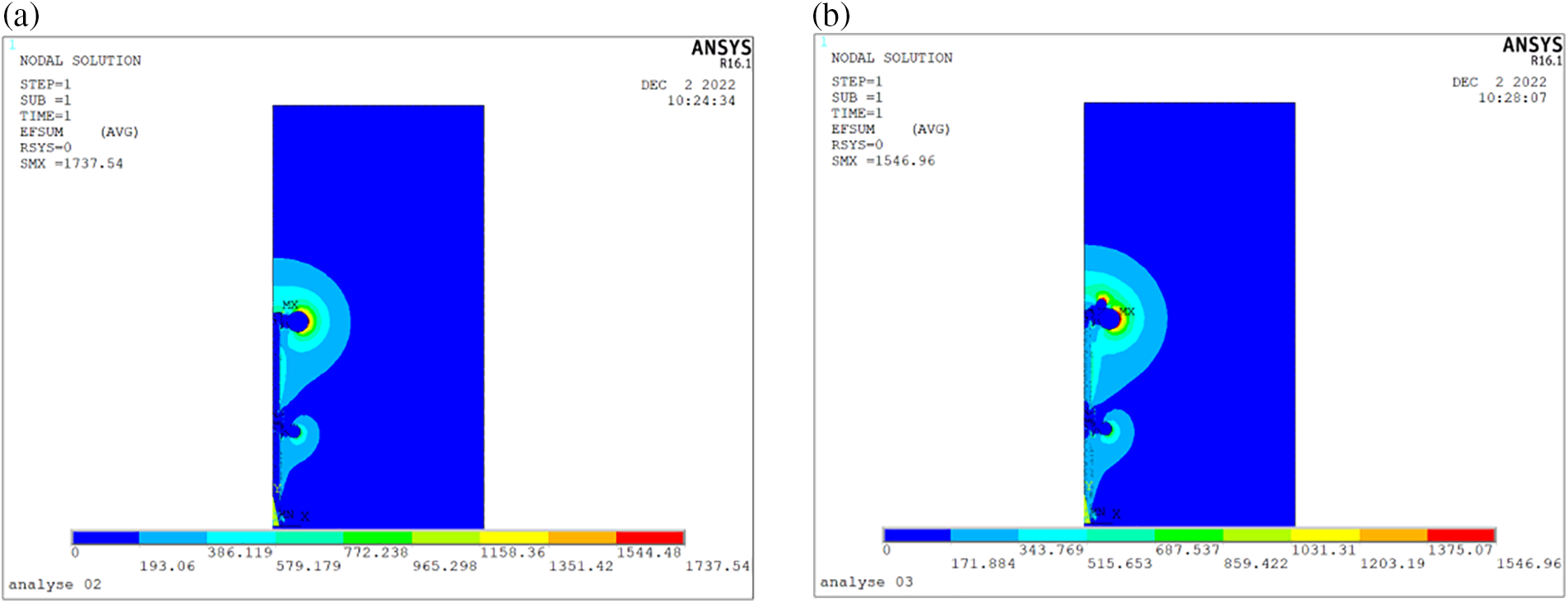
Figure 8: Electric field distribution of 2 × 600 kV DC resistive standard divider. (a) Without installing auxiliary grading ring; (b) Installing auxiliary grading ring
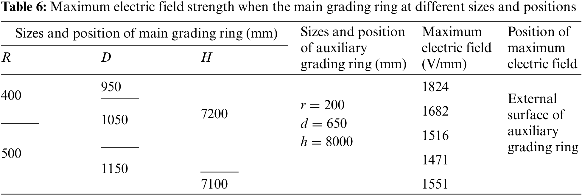
4.2.2 Effect of the Size and Position of Grading Ring on the Maximum Electric Field Strength
The maximum field strength of the voltage divider is related to the size and installation position of the main and auxiliary grading rings. Fig. 9 is a schematic diagram of the size and installation position of the grading ring.
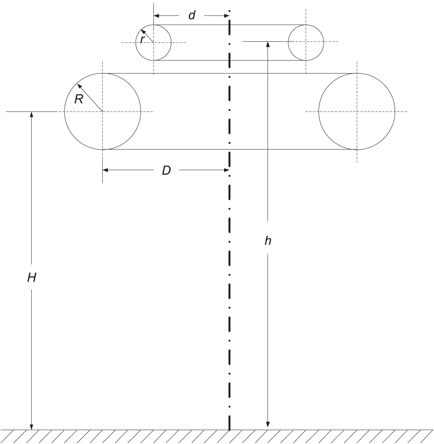
Figure 9: Schematic diagram of the size and installation position of the grading ring
Limited by objective factors such as economic cost, design, and manufacturing level, and considering the voltage divider’s height constraints, the grading rings’ size and position will not vary significantly. In this paper,
When
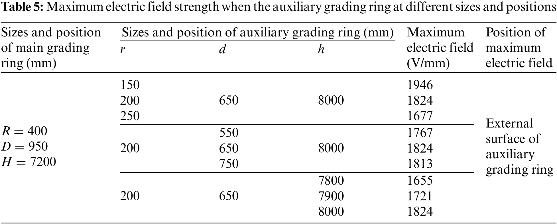
As can be seen:
(1) The position of the maximum field strength is on the outer surface of the auxiliary grading ring.
(2) The maximum field strength decreases from 1946 to 1677 V/mm as the
(3) When
(4) With the increase of
When
As can be seen:
(1) The position of the maximum field strength is on the outer surface of the auxiliary grading ring.
(2)When
(3) When
After optimization design, the maximum electric field strength of 1200 kV DC resistive divider was reduced to 1471 V/mm. As for 2 × 600 kV DC resistive standard divider, the optimization design was carried out. The maximum electric field strength of 2 × 600 kV DC resistive divider was reduced to 1348 V/mm (
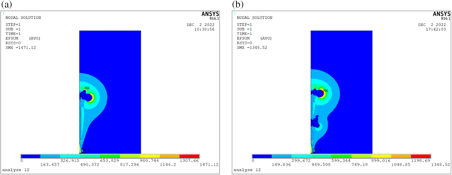
Figure 10: Electric field distribution of DC resistive standard divider after optimization design. (a) 1200 kV divider; (b) 2 × 600 kV divider
The maximum electric field strength of the 2 × 600 kV DC resistive divider is lower than that of the 1200 kV. Therefore, it can be concluded that the design method of 2 × 600 kV is desirable from the view of the electric field.
4.2.3 Electric Field Simulation Results of Measuring Resistor Layer
In the case of 1200 kV DC resistive divider without shielding resistor layer, the electric field distribution of the measuring resistor layer is calculated and measured. The results are shown in Fig. 11. The distribution of the synthetic electric field is not uniform. In addition, the distribution of transverse electric field components is also not uniform, and the maximum electric field strength is about 370 V/mm. However, the distribution of the longitudinal electric field component is uniform, because the measured resistor voltage is uniform along the longitudinal direction.
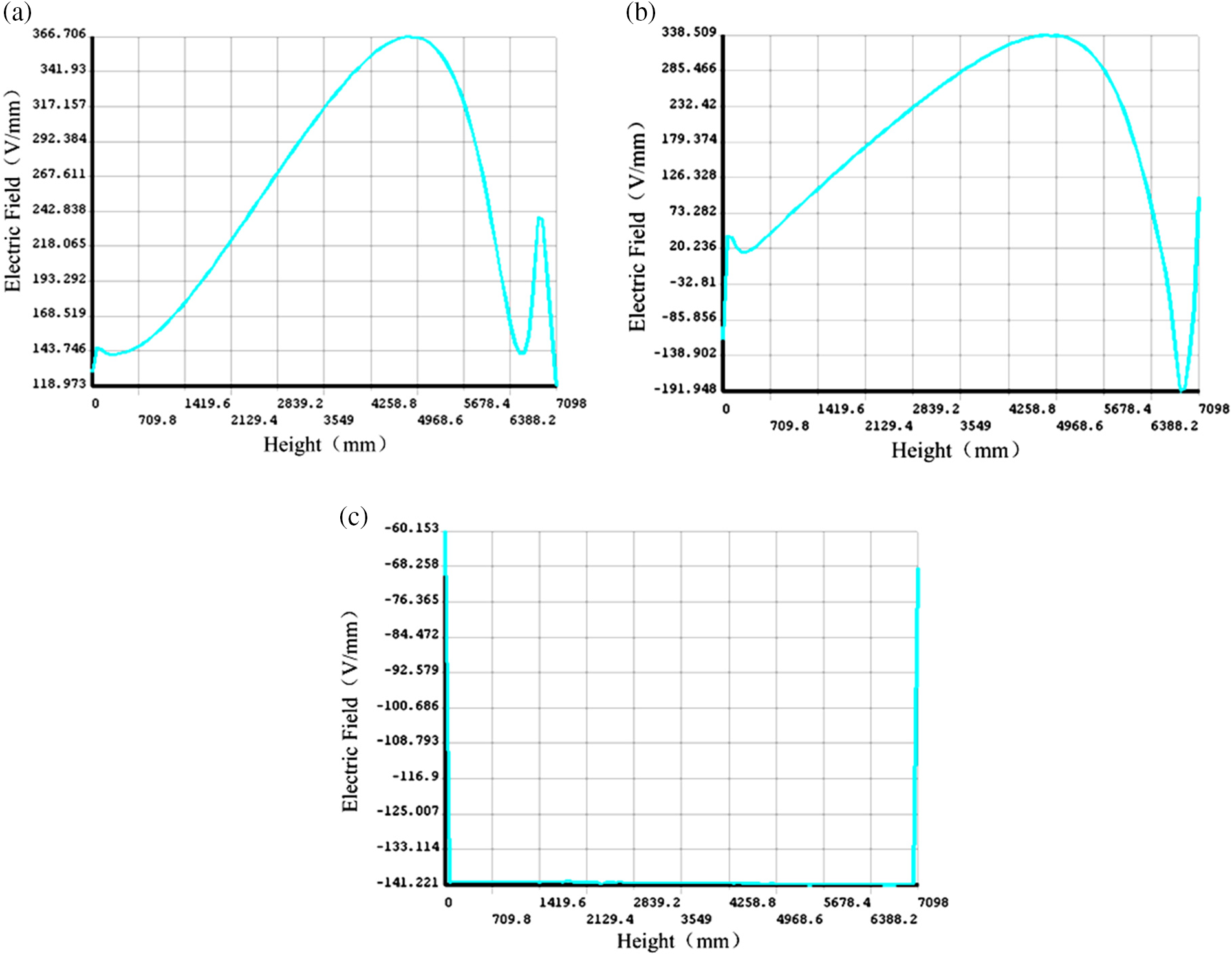
Figure 11: Electric field distribution without shielding resistor layer. (a) Synthetic electric field; (b) Transverse electric field components; (c) Longitudinal electric field components
In the case of the 1200 kV DC resistive divider with a shielding resistor layer, the electric field distribution of the measuring resistor layer is calculated and measured. The results are shown in Fig. 12. It can be seen from the figure that the distribution of the synthetic electric field is uniform. In addition, the transverse and longitudinal electric field components are also uniformly distributed, and the transverse component is minimal, almost equal to 0. This is because the shielding resistor layer shielded the measuring resistor layer by equipotential shielding.
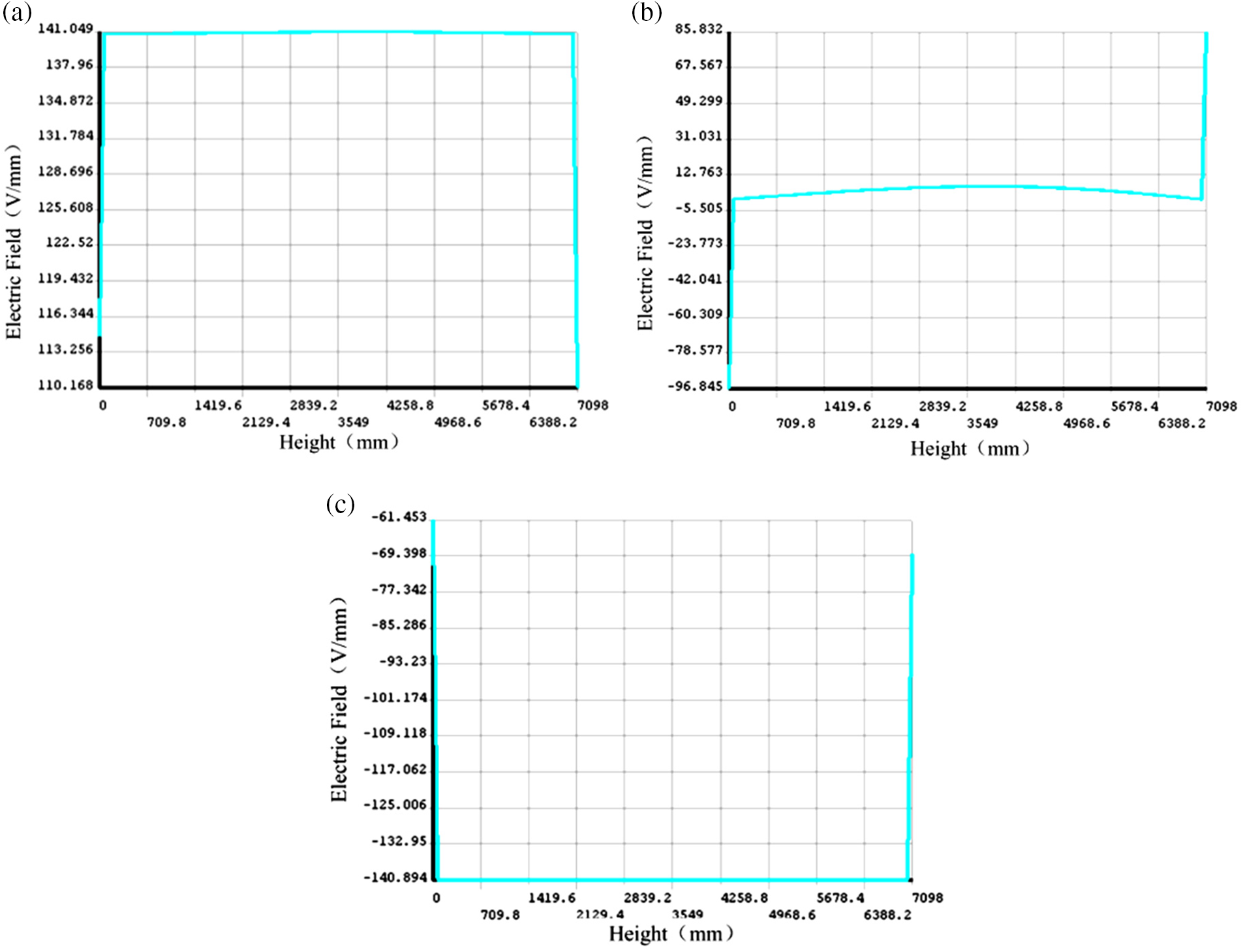
Figure 12: Electric field distribution with shielding resistor layer. (a) Synthetic electric field; (b) Transverse electric field components; (c) Longitudinal electric field components
Therefore, it is necessary to install a shielding resistor layer on the developed 1200 kV DC resistive divider. Finally, the electric field strength of the synthetic electric field along the measuring resistor layer is reduced to 141 V/mm, and the distribution is uniform.
This paper investigates the thermal analysis and electric field optimization of a high voltage DC resistive divider. The following conclusions can be drawn:
(1) Most of the heat of the partition is transferred to the air through the insulating bushing. There is a linear relationship between the temperature of the insulating medium, the voltage divider’s power, and the air temperature. Under the same ambient temperature and voltage divider power, the temperature of the insulating oil is slightly higher than that of nitrogen, about 3°C.
(2) If the developed 1200 kV DC voltage divider uses nitrogen or insulating oil of similar size as the insulating medium, when the power does not exceed 400 W and the laboratory temperature is within the range of 20°C ± 5°C, the nitrogen temperature will rise to 40°C around, to meet the ambient temperature requirements of the resistor.
(3) The 1200 kV DC resistive standard voltage divider should adopt the form of main and auxiliary voltage grading rings. After the optimized design, the maximum electric field strength of the 1200 kV DC resistive divider is reduced to 1471 V/mm, about 24% lower than that of the unoptimized design. For the 2 × 600 kV DC resistive standard divider, the maximum electric field strength is reduced to 1348 V/mm.
(4) The developed 1200 kV DC resistive divider must be equipped with a shielding resistor layer. The electric field strength of the synthetic electric field along the measuring resistor layer is reduced to 141 V/mm, and the distribution is uniform.
Acknowledgement: We thank the reviewers for providing valuable revisions to the paper and the editors for the layout and copy-editing work.
Funding Statement: This work was supported by the Science and Technology Project of China Electric Power Research Institute, Research on 1200 kV DC Voltage Proportional Metering Technology with Weak Environmental Sensitivity and Development of Standard Devices (JL83-21-002).
Author Contributions: The authors confirm contribution to the paper as follows: study conception and design: Dengyun Li, Jicheng Yu; data collection: Baiwen Du, Siyuan Liang; analysis and interpretation of results: Dengyun Li, Kai Zhu, Changxi Yue; draft manuscript preparation: Dengyun Li, Jicheng Yu. All authors reviewed the results and approved the final version of the manuscript.
Availability of Data and Materials: The datasets used or analyzed during the current study are available from the corresponding author on reasonable request.
Conflicts of Interest: The authors declare that they have no conflicts of interest to report regarding the present study.
References
1. Ma, Y., Li, H., Wang, G., Wu, J. (2018). Fault analysis and traveling-wave-based protection scheme for double-circuit LCC-HVDC transmission lines with shared towers. IEEE Transactions on Power Delivery, 33(3), 1479–1488. https://doi.org/10.1109/TPWRD.2018.2799323 [Google Scholar] [CrossRef]
2. Shu, Y., Chen, W. (2018). Research and application of UHV power transmission in China. High Voltage, 3(1), 1–13. https://doi.org/10.1049/hve.2018.0003 [Google Scholar] [CrossRef]
3. Liu, Z. (2020). Findings in development of ±1100 kV UHVDC transmission. Proceedings of the CSEE, 40(23), 7782–7791. [Google Scholar]
4. Ding, Y., Li, J., Su, Y., Qiu, Z., Yao, X. (2022). Safety distance test and electric field distribution characteristics of ±1100 kV tension string two-person live working. Chinese Society for Electrical Engineering, 10(2), 1–10. [Google Scholar]
5. Cao, F., Li, B., Dong, H., Bai, F., An, J. et al. (2023). Measurement and analysis of DC tnterference between ±1100 kV UHV DC grounding electrodes and buried oil and gas pipelines. High Voltage Apparatus, 59(2), 1001–1011. [Google Scholar]
6. Takahashi, A., Suto, T., Fujita, H., Hiranuma, Y., Ichimura, S. et al. (2021). –1 MV DC filter and high-voltage DC measurement system for ITER neutral beam injector system. IEEE Transactions on Power Electronics, 36(7), 7587–7599. https://doi.org/10.1109/TPEL.2020.3041661 [Google Scholar] [CrossRef]
7. Souza, L., Pinto, M., Martins, M. B., Lima, A. (2021). Modeling of a resistive voltage divider by rational functions: Uncertainty evaluation. IEEE Transactions on Instrumentation and Measurement, 70, 1–8. https://doi.org/10.1109/TIM.2020.3047956 [Google Scholar] [CrossRef]
8. Kim, K. T., Jung, J. K., Yu, K. M., Kim, Y. B., Song, Y. S. (2017). Modified step-up method for calibration of DC high-voltage dividers. IEEE Transactions on Instrumentation and Measurement, 66(6), 1103–1107. https://doi.org/10.1109/TIM.2017.2660078 [Google Scholar] [CrossRef]
9. Liu, K., Li, D., Zhu, K., Lei, M., Zhou, F. et al. (2022). Traceability of 1 kV DC voltage ratio based on 2/1 self-calibration method. High Voltage Engineering, 48(6), 2226–2233. [Google Scholar]
10. Li, Z., Jiang, W., Abu-Siada, A., Li, Z., Xu, Y. et al. (2021). Research on a composite voltage and current measurement device for HVDC networks. IEEE Transactions on Industrial Electronics, 68(9), 8930–8941. https://doi.org/10.1109/TIE.2020.3013772 [Google Scholar] [CrossRef]
11. Yamada, T., Tachibana, K., Shioda, T. (2021). Design method for a wideband resistive voltage divider based on average impedance matching with optimal solution methods. IEEE Transactions on Instrumentation and Measurement, 70, 1–7. https://doi.org/10.1109/TIM.2020.3014034 [Google Scholar] [CrossRef]
12. Wang, B., Wang, R., Wu, S., Ye, Z., Xu, S. (2022). Research on the heat exchange structure designing for UHV DCVT and its influence on error characteristics. Electrical Measurement & Instrumentation, 59(1), 84–92. [Google Scholar]
13. Xie, T., Yang, Z., Feng, J., Wang, L. (2017). Influence of temperature variation on the accuracy of DC voltage measuring device. 2017 4th International Conference on Electric Power Equipment-Switching Technology (ICEPE-ST), pp. 829–832. Xi’an, China. [Google Scholar]
14. Feng, J., Wang, S., Zhao, L., Chen, B., Zeng, L. et al. (2016). Study on the internal temperature distribution of UHVDC voltage measuring device. High Voltage Apparatus, 52(6), 41–45. [Google Scholar]
15. Li, D., Liu, K., Lei, M., Zhou, F., Yue, C. et al. (2020). Study on the ratio change measurement of 1000 kV HVDC divider based on improved DC voltage summation method. High Voltage, 5(2), 202–208. https://doi.org/10.1049/hve.2019.0127 [Google Scholar] [CrossRef]
16. Zhang, H., Lin, F., Shao, H., Zhang, Z. (2018). Research on measuring leakage current of DC high-voltage resistive divider. Acta Metrologica Sinica, 39(1), 83–88. https://doi.org/10.18654/1000-0569/2023.01.05 [Google Scholar] [CrossRef]
17. Li, X., Wang, Y., Xiao, W., Xu, Y., Zhu, W. et al. (2021). Electric field optimization of 1MV DC-GIL spacer with surface conductivity gradient for ITER NBI. IEEE Transactions on Applied Superconductivity, 31(8), 1–4. https://doi.org/10.1109/TASC.2021.3111856 [Google Scholar] [CrossRef]
18. Liu, W., Ye, Y., Hu, J., Li, C., Liu, Y. (2019). Principle and insulation structure analysis of the 800 kV DC voltage measuring device. Power System and Clean Energy, 35(7), 45–54. [Google Scholar]
19. Liu, K., Li, K., Chang, Z., Fan, C., Hu, S. (2022). Research on losses and heat dissipation of saturable reactor used in converter valve. IEEE Access, 10, 17796–17802. https://doi.org/10.1109/ACCESS.2022.3148271 [Google Scholar] [CrossRef]
20. Chen, W., Cai, L., Zhao, K., Zhang, X., Liu, X. et al. (2018). Analytical multistage thermal model for FEOL reliability considering self-and mutual-heating. IEEE Transactions on Electron Devices, 65(9), 3633–3639. https://doi.org/10.1109/TED.2018.2853713 [Google Scholar] [CrossRef]
21. Khan, N. A., Sulaiman, M., Kumam, P., Bakar, M. A. (2021). Thermal analysis of conductive-convective-radiative heat exchangers with temperature dependent thermal conductivity. IEEE Access, 9, 138876–138902. https://doi.org/10.1109/ACCESS.2021.3117839 [Google Scholar] [CrossRef]
22. Wang, Z., Yan, F., Xu, M., Wang, Z., Wang, X. et al. (2017). Influence of external factors on self-healing capacitor temperature field distribution and its validation. IEEE Transactions on Plasma Science, 45(7), 1680–1688. [Google Scholar]
23. Fan, Y., Weng, L., Luo, S., Wang, Z. (2018). Research on the insulation characteristics of ±1100 kV UHVDC electronic voltage transformer. High Voltage Apparatus, 54(6), 164–169. [Google Scholar]
24. Yang, X., Yang, Z., Zhang, Y., Li, C., Qi, B. (2022). Simulation analysis of electrical-thermal-fluid coupling property for supporting insulation in SF6 filled HVDC apparatus. IEEE Transactions on Dielectrics and Electrical Insulation, 29(1), 69–76. [Google Scholar]
25. Wang, J., Yue, B., Deng, X., Liu, T., Peng, Z. (2018). Electric field evaluation and optimization of shielding electrodes for high voltage apparatus in ±1100 kV indoor DC yard. IEEE Transactions on Dielectrics and Electrical Insulation, 25(1), 321–329. [Google Scholar]
26. Li, N., Peng, Z., Liu, P. (2020). Electric field simulation and analysis of 1100 kV DC SF6 gas-insulated wall bushing. High Voltage Engineering, 46(1), 205–214. [Google Scholar]
Cite This Article
 Copyright © 2023 The Author(s). Published by Tech Science Press.
This work is licensed under a Creative Commons Attribution 4.0 International License , which permits unrestricted use, distribution, and reproduction in any medium, provided the original work is properly cited.
 Downloads
 Citation Tools