
 Submit a Paper
 Propose a Special lssue
 Open Access
ARTICLE

Analysis of Sub-Synchronous Oscillation of Virtual Synchronous Generator and Research on Suppression Strategy in Weak Grid
Jianbi Power Plant of National Energy Group, Zhenjiang, 21200, China
* Corresponding Author: Lin Chen. Email:
Energy Engineering 2023, 120(11), 2683-2705. https://doi.org/10.32604/ee.2023.029620
Received 16 December 2022; Accepted 13 April 2023; Issue published 31 October 2023
 View Full Text
 Download PDF
Abstract
At present, the direct drive permanent magnet synchronous generator (DD-PMSG) grid connected system based on virtual synchronous generator (VSG) control will experience power oscillation at sub synchronous frequencies. The mechanism and characteristics of this new type of sub-synchronous interaction (SSI) are not yet clear, and the system cannot recover to steady state solely based on the characteristics of VSG itself. Especially when connected to a weak current network, oscillations are more pronounced, affecting the stability of the system. In severe cases, the system may trigger shutdown protection and be disconnected from the network. Existing research has only analyzed the oscillation mechanism under this phenomenon and has not proposed corresponding control strategies. This article proposes a VSM control strategy based on the VSG control algorithm, which balances the dq axis component of voltage and current, and improves the voltage and current loop of VSG control to reduce the impact of sub-synchronous oscillation (SSO) on the power grid. In MATLAB/Simulink, a simulation model of the proposed control strategy was built to verify its correctness and effectiveness.Keywords
Nomenclature
| COA | Chaotic optimization algorithm |
| DD-PMSG | Direct-drive permanent magnet synchronous generator |
| DFIG | Doubly fed induction generator |
| ECKF | Extended complex Kalman filter |
| FACTS | Flexible AC transmission system |
| GSC | Grid-side converter |
| HVDC | High-voltage direct current |
| IGE | Inductive generator effect |
| IMM | Interactive multi-model |
| ML | Maximum likelihood |
| MRF | Median regression function |
| NFs | Notch filters |
| PLL | Phase-locked loop |
| PMSG | Permanent magnet synchronous generator |
| PMU | Phasor measurement unit |
| PSO | Particle swarm optimization |
| RSC | Rotor-side converter |
| SCR | Short-circuit ratio |
| SG | Synchronous generator |
| SMES | Superconducting magnetic energy storage |
| SSCI | Sub-synchronous Control Interaction |
| SSDC | Sub-synchronous damping controller |
| SSI | Sub-synchronous interaction |
| SSO | Sub-synchronous oscillation |
| SSR | Sub-synchronous resonance |
| STATCOM | Static synchronous compensator |
| SVC | Static reactive power compensator |
| TA | Transient torque amplification |
| TI | Torsional interaction |
| VSC | Voltage source converter |
| VSG | Virtual synchronous generator |
By the end of 2021, China’s installed capacity of power generation was 2,200.58 million kilowatts (MWs), which increases by 9.5% over the end of last year. Among them, the installed capacity of thermal power and hydropower increased by 4.7% and 3.4%, respectively; the installed capacity of grid-connected wind power was 281.53 MWs, which increases by 34.6%; the installed capacity of grid-connected solar power was 253.43 MWs, an increase of 24.1% [1]. It can be seen that the installed capacity of thermal power and hydropower has increased significantly, and the installed capacity of grid-connected wind power and solar power has grown rapidly. Unfortunately, with the rapid growth of wind power, sub-synchronous oscillations (SSO) have been observed in some wind farms with weak grid interconnection. SSO greatly affects the stability of the system, and in severe cases, the system may trigger shutdown protection and be disconnected from the network. This article analyzes the SSO phenomenon caused by the direct drive wind power grid-connected system passing through long-distance transmission lines. On the one hand, we suppress the impact of SSO on the power grid, and on the other hand, we improve the performance of VSG under frequency oscillation.
In recent years, virtual synchronous generator (VSG) technology [2] has been used to control grid-connected inverters. It borrows the mechanical and electromagnetic equations from the SG [3] while combining inertia characteristics [4], active power regulation frequency [5] and reactive power regulation voltage [6]. However, VSGs borrowed from SG will also have all the advantages and disadvantages of synchronous machines, such as the possibility of bad phenomena in synchronous inverters; loss of stability due to under-excitation and oscillations [7].
In the steady-state or small disturbance of the power system, the oscillation of the traditional power system is mainly divided into the low-frequency oscillation (0.5~3 Hz) and the SSO (<50 Hz) of the local generator and external network [8]. With the increasing proportion of power electronic equipment in the power system, the broadband oscillation of modern power systems is mainly divided into resonance and control oscillation. The resonance dominated by power electronic equipment is caused by the generation and transmission of new energy, while the control oscillation is caused by the integration of new energy into the grid. Two types of oscillations will be briefly described below:
(1) Resonant class oscillations are caused by inductive-capacitive LC resonant circuits. This oscillation contains three subclasses: conventional sub-synchronous resonance (SSR), ferromagnetic resonance, and power electronics-dominated resonance. Based on the destabilization mechanism, conventional SSR can be further classified into induction generator effect (IGE), torsional interaction (TI) and transient torque amplification (TA). Ferromagnetic resonance is a form of self-excited oscillation in power systems and is a resonant phenomenon generated by the nonlinear inductance of transformers, voltage transformers and other components in substations, as well as the grounding capacitance of cables and overhead lines. Main resonances in power electronics include high frequency resonances in flexible DC transmission systems, resonances in doubly-fed turbines through series complementary feeder systems, and high frequency switching or control triggered resonances in voltage source converters (VSCs).
(2) For control oscillations, there is no LC electrical resonance loop in the system and the power electronic controller has a significant influence on such oscillations. This type of oscillation includes two subcategories of SSO and power electronic dominated control oscillations. Conventional SSO refers to the sub-synchronous oscillation phenomenon caused by the interaction between the synchronous generator shaft system and the fast control characteristics of the power electronics of high-voltage direct current (HVDC) or flexible AC transmission systems (FACTS) [9,10]. The dynamic interaction between the VSC equipment and the weak grid causes the direct-drive wind power control system to exhibit negative damping of the sub-synchronous oscillation mode, which triggers the sub/super-synchronous oscillation phenomenon. In large-scale new energy sites, SSO with time-varying frequencies can be monitored by means of series complementary or weak AC grid systems [11,12]. This phenomenon is related to the converter control and line series complement capacitance of the doubly-fed induction wind turbine and is not related to the shaft torsional oscillation and is referred to as sub-synchronous Control Interaction (SSCI). Some studies have shown that there is also SSCI between the VSG and the weak power grid [13]. Reference [14] presented a literature review on the damping of power system oscillations. The study identifies various control design techniques, technologies and features used in power systems. In addition, it discusses various devices and tools for minimizing damping in conventional grids and renewable energy sources.
With the frequent occurrence of oscillations, online monitoring and accurate alarming of the power system are essential for its safe and stable operation. A phasor measurement unit (PMU) enables dynamic real-time monitoring of the power system [15]. However, where the use of series capacitors in long-distance transmission lines can lead to SSO, the SSO phenomenon must be accurately detected within a short time. An efficient, safe and improved method of SSO detection based on voltage signals is proposed, where the voltage magnitude signal is passed through a first order bandpass filter only via a sub-synchronous frequency and the best decision is made in the decision phase (single sign-on detection, immediate tripping or normal tripping) based on the data received from the analysis phase [16].
The traditional power system oscillation problems have more mature theories and methods in terms of mechanism research, characteristic analysis and oscillation suppression. However, in the new power system, the broadband oscillations caused by power electronics present new phenomena and characteristics, such as various forms, broadband characteristics, time-varying characteristics and wide-area propagation characteristics. A new strategy for suppressing SSO in series capacitor compensated power systems by controlling the active power of superconducting magnetic energy storage (SMES) devices was proposed in [17]. The strategy is based on the generator acceleration signal and the chaotic optimization algorithm (COA) is used to obtain the optimal parameters of the proposed controller. However, reactive power is not taken into account. Reference [18] proposed a method to control the active and reactive power of a SMES system based on reference [17], which prioritises active power over reactive power, with primary frequency and voltage control used to calculate active and reactive power reference values for the SMES system, and these gains are calculated by a particle swarm optimization (PSO) algorithm. A median regression function (MRF) based state estimation method was proposed in reference [19]. The algorithm uses an interactive multi-model (IMM)-based fusion architecture deployed on each monitoring node. The system considers an exogenous variable-driven representation of the state. Initial regression analysis based on mapping functions is used to describe the state estimation bounds at the time of data injection. An improved PLL was proposed to replace the conventional phase-locked loop in reference [20]. Aiming at the problem that the control of the rotor-side converter (RSC) and grid-side converter (GSC) in the doubly fed induction generator (DFIG) wind power system is disturbed by harmonic signals under SSO, it is proposed to add the quasi-resonance controller to the RSC and GSC to suppress SSO. However, both traditional PI control and quasi-resonant controllers have the problem of insufficient robustness. To reduce the SSO of the permanent magnet synchronous generator (PMSG), an energy shaping L2 gain controller (ESLGC) for the MSC and the GSC was proposed in reference [20]. This ESLGC has better robustness and damping performance under various operating conditions. However, ESLGC does not use non-linear analysis techniques to assess the performance of the damping controller, which has resulted in less widespread use. Several scholars have investigated the use of static reactive power compensators (SVCs) and TCR-FCs (silicon controlled rectifiers with fixed capacitors) to suppress SSO [21]. The collection of reactive power variations, frequency variations, active power variations and current variations can be used to enhance the dynamic response of the system. However, Reference [21] only captures reactive power changes and does not further combine the two signals into a single controller. Similarly, a new auxiliary sub-synchronous damping controller (SSDC) has been proposed for transmission lines with series compensation [22] and an auxiliary SSDC for static synchronous compensator (STATCOM), which uses the generator rotor speed deviation signal as a stabilising signal [23]. In contrast to reference [22], MMC-STATCOM proposes an additional broadband damping controller that provides an additional broadband damping control strategy to mitigate SSCI. This method uses notch filters (NFs) to filter only the fundamental frequency component of the current to obtain the corresponding sub-synchronous component to generate the damping control signal [24]. This strategy does not require phase compensation and, in contrast to previous studies, always allows the extraction of the corresponding sub-synchronous components. For SSO caused by weak grids, an impedance model of VSG under weak grids was developed and the mechanism and characteristics of the occurrence of sub-synchronous resonance (SSR) in the analysis [25]. Using small-signal analysis [26,27], key parameters such as the PLL were examined. References [28,29] improved the existing extended complex Kalman filter (ECKF) technique to track electromechanical oscillations using simultaneous phase measurements. Not only can the distributed structure be estimated to estimate the oscillation parameters of the local substation, but also the ability to detect multiple oscillations with similar frequencies can be improved.
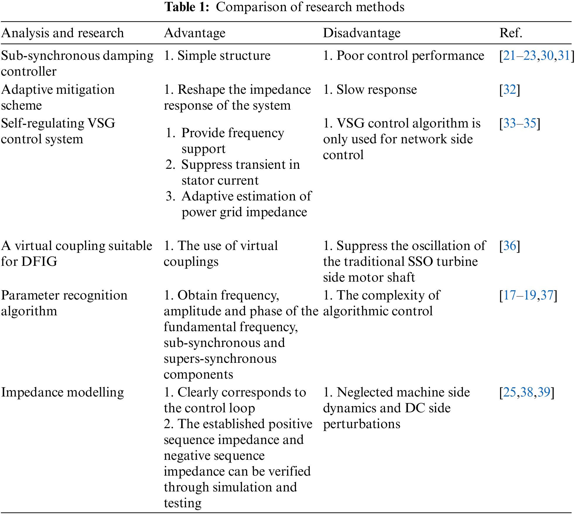
In summary, there are many new challenges to study and analyze SSO. Table 1 lists the current mainstream studies on suppressing SSO, and in response to the shortcomings of the above studies, this paper considers the frequency coupling effect and uses VSM-VSG cooperative control to effectively suppress SSO and provide frequency support for the system.
This study uses an analytical model of a type IV wind power system on a weak current network to demonstrate sub-synchronous frequency oscillations. Firstly, considering the frequency coupling effect, impedance model analysis is conducted on VSG. The purpose of drawing a Bode diagram is to examine key factors and determine the root causes of such instability and resonance problems. To improve the SSO suppression ability of VSG, the application of VSM control strategy on the machine side and a new voltage and current dual loop control strategy on the network side were studied. This control strategy improves the grid connection voltage and current waveform by adding the dq component of the grid voltage to the GSC, in order to meet the requirements of harmonic suppression under different weak current grid conditions. The simulation results show that this method can effectively suppress the impact of SSO on the power grid.
The main contributions of this paper are summarized below:
1. VSG impedance model was analyzed based on frequency coupling effect and DC side disturbance to study the influence of VSG parameters on SSO suppression.
2. Use the VSM control policy to increase damping and inertia during the oscillation period to provide frequency support for the system. The dq axis components of voltage and current are balanced by adding the dq component of grid voltage to the GSC side to form feedback.
The current dissertation organization is continued. Section 2 presents the general principles of the VSG control technique. Section 3 presents the complete Type IV wind power model. Section 4 models the impedance of the PLL and VSG. Section 5 presents the effect of the parameters of impedance modelling on the bode plots and the results of adopting the suppression strategy. Section 6 is the conclusion.
The classic control block diagram of VSG is shown in Fig. 1, where
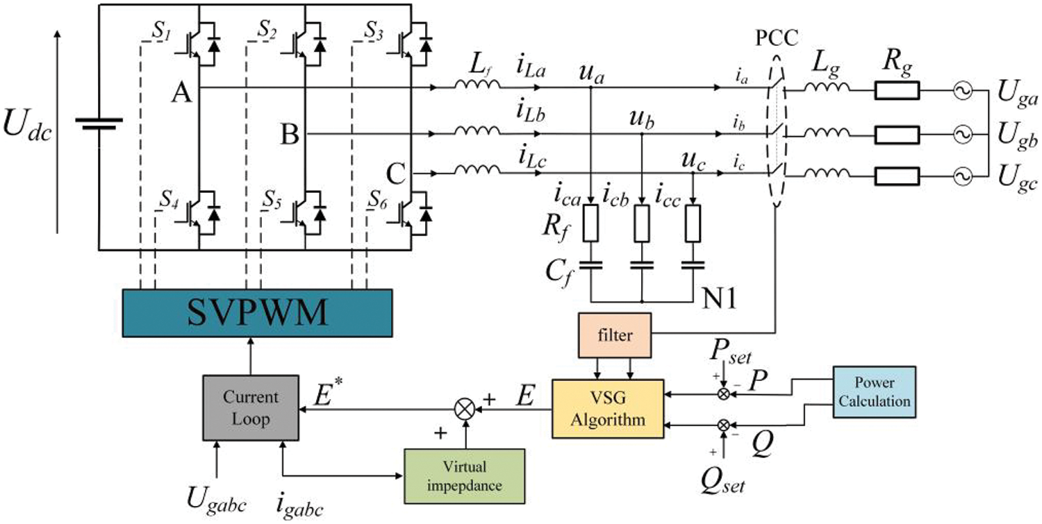
Figure 1: VSG-class control block diagram
The traditional SGs adjust the active output of the generator by adjusting the mechanical torque and realising the response to the frequency deviation of the grid through the frequency regulator. Based on this principle, the adjustment of the active command of the grid-connected inverter is realized by adjusting the virtual mechanical torque
where
Furthermore, the potential voltage vector of the VSG can be obtained as:
where
As shown in Fig. 1, the relationship between the internal potential of the VSG, the output terminal voltage and the output current can be as follows:
Under the disturbance of small signal, the voltage and current of the AC port of the converter contain the fundamental frequency component, the disturbance frequency component and the coupling frequency component. Taking phase A as an example, the time domain expressions of voltage and current of the converter port are, respectively:
where the fundamental frequency voltage and current amplitudes are
Fourier transforms the corresponding time-domain expressions of Eqs. (7) and (8) into:
where
The new energy and grid interconnection system can be simplified in Fig. 2. The DC link is mainly composed of capacitors, which stabilize the DC voltage rectified by the machine-side rectifier at a fixed value.
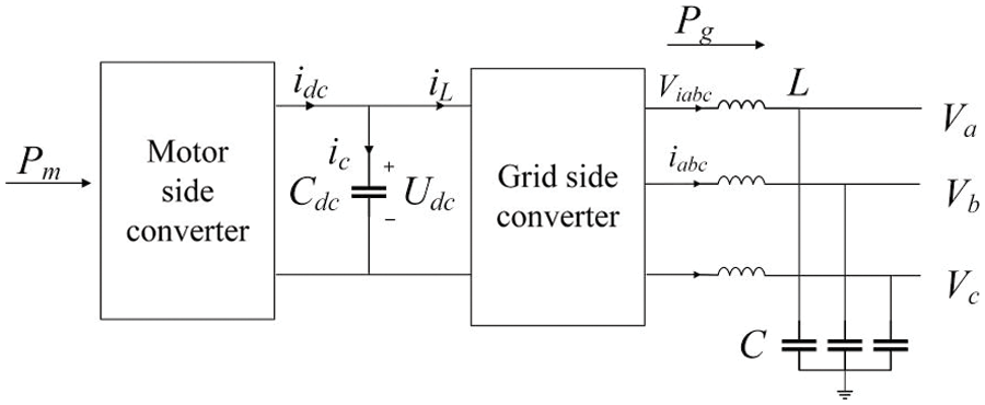
Figure 2: DC link structure diagram
In Fig. 2,
In order to effectively transmit power,
It can be seen from the power balance that the power output at the machine side should be equal to the power absorbed by the grid, that is:
The implementation of VSG control requires the use of a suitable inverter control structure. Commonly used control methods are P/Q control, V/F control and Droop control. VSG control algorithms can be divided into two main categories, which are described below:
P/Q control, composed of an outer power loop and an inner current loop, can realize the constant power output of the distributed generator. P/Q control is widely used in grid-connected VSG units. When P/Q control is applied in grid-connected mode, the active power can obey the governor’s scheduling command well.
V/F control can output a constant voltage and frequency. This control method is more common when the island VSG. The VSG achieves amplitude control of the voltage by simulating the excitation regulation of the SG. The output voltage is adjusted according to the VSG output voltage deviation and the voltage regulation capability is characterized by a voltage regulation factor. Fig. 3 is the active power and reactive power control block diagram of the VSG.
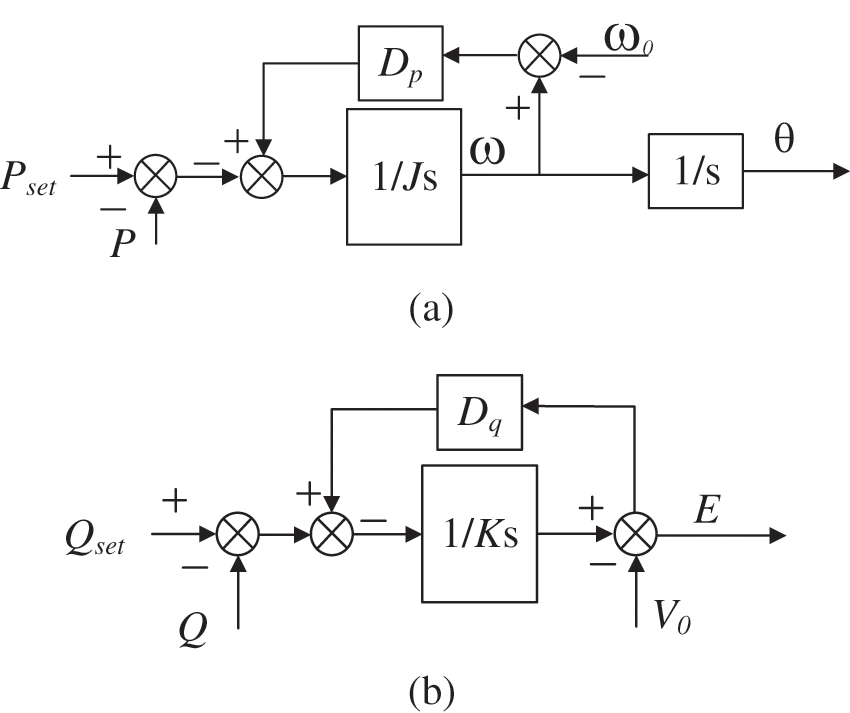
Figure 3: VSG control (a) active power control (b) reactive power control
It has been found that there is a strong coupling effect between the frequency
Using the frequency convolution theorem, power in the frequency domain can be obtained:
where
In Fig. 3,
Substituting Eqs. (13) and (14) into Eqs. (15) and (16).
The output reactive power of the voltage-controlled VSG is determined by the voltage amplitude difference on the filter inductor
The voltage-current loop controlled by VSG is shown in Fig. 4.
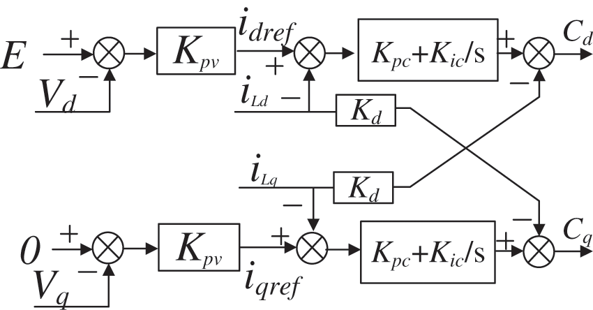
Figure 4: Voltage and current double closed loop
In Fig. 4, the modulation through the voltage and current double loops can be obtained as:
where
When a phase angle disturbance occurs in the PLL,
Integrating Eqs. (20)–(23),
The admittance matrix can be obtained by impedance.
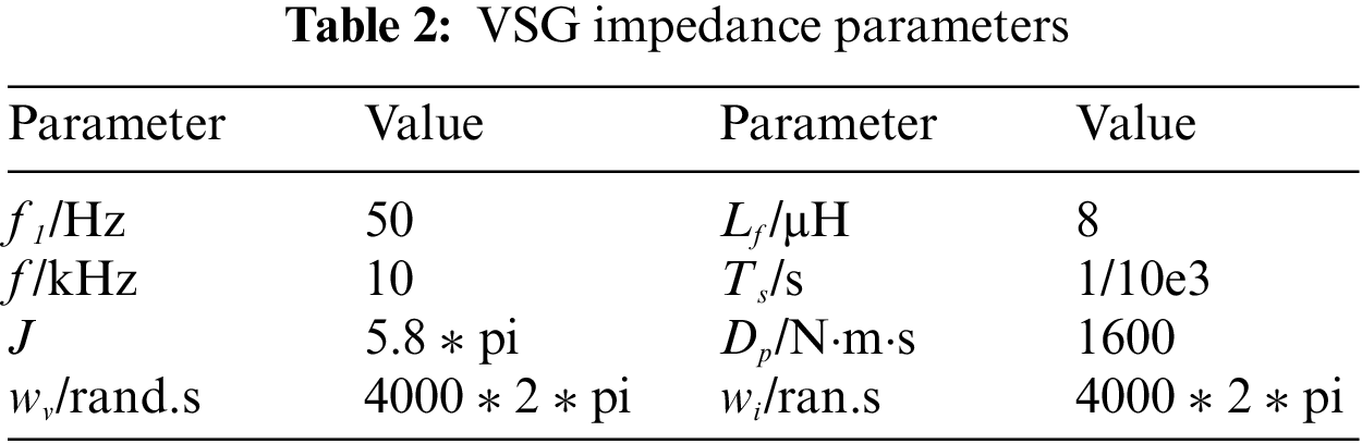
Fig. 5 is the Bode diagram of the VSG positive sequence impedance, the parameters are shown in Table 2. The moment of inertia
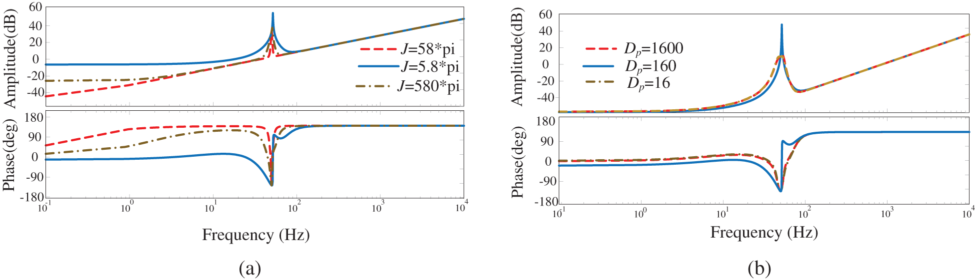
Figure 5: VSG positive sequence impedance bode. (a) VSG positive sequence impedance when
The VSG output impedance can be improved by changing the parameters in the active and reactive loops, but changing the parameters of the power loop will have an impact on the dynamic stability performance of the VSG.
In Figs. 6a and 6b,
Figure 6: Bode plot of VSG output impedance during J transformation
It can be seen in Fig. 7. When
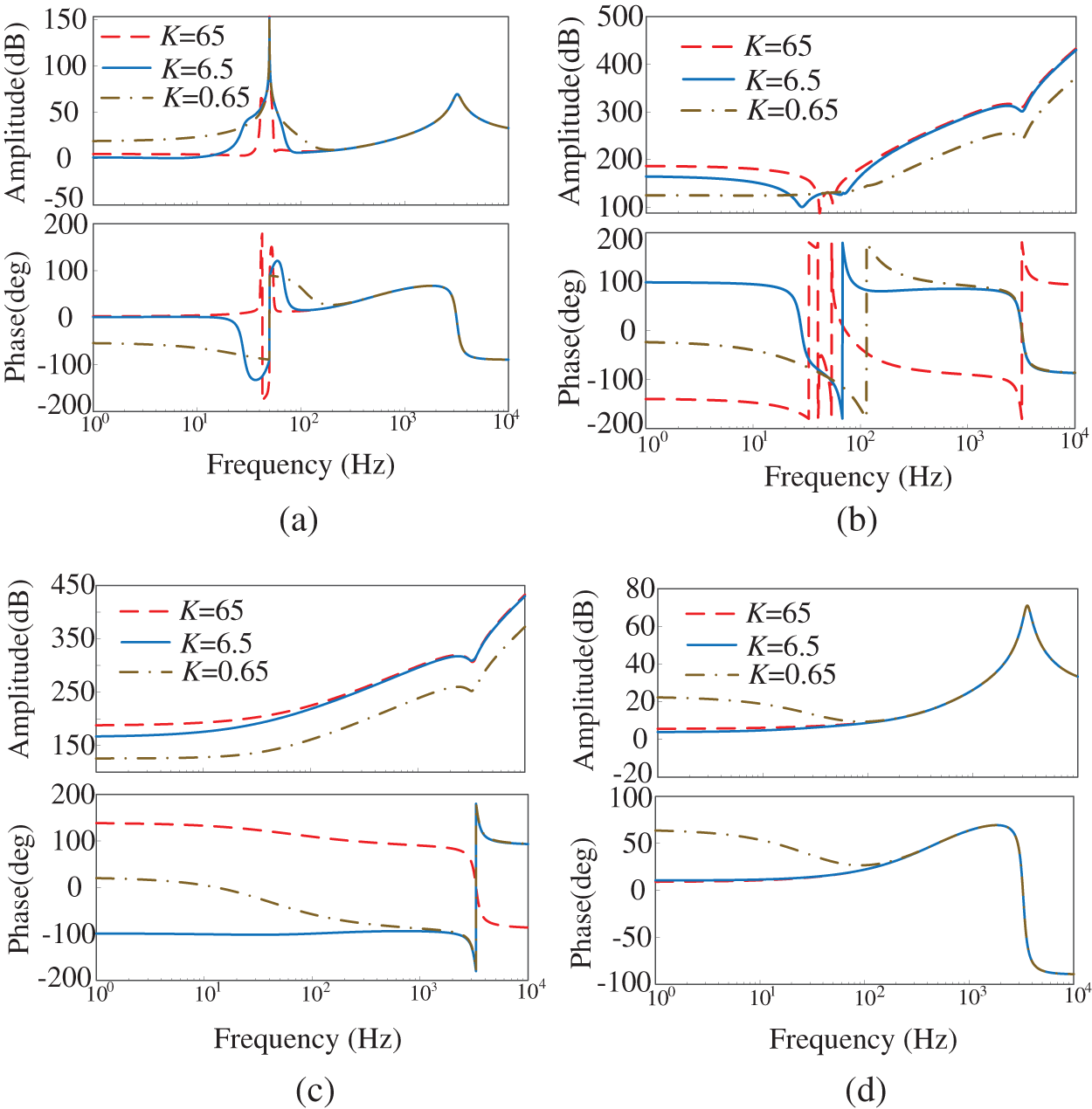
Figure 7: Bode plot of VSG output impedance during K transformation
In this section, the VSM-VSG collaborative control strategy was adopted, as shown in Fig. 8 which mainly includes VSM control on the machine side and VSG control on the network side.
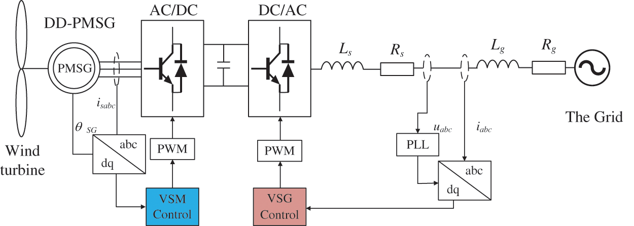
Figure 8: Control block diagram of VSM-VSG
Generally, when the SCR is 2~3, it is a weak connection, and when the SCR is less than 2, it is a very weak connection. The connection strength to the AC grid is usually characterized by the connection reactance value. The larger the connection reactance, the weaker the AC system strength, the lower the SSO frequency, the weaker the damping, and the higher the risk of unstable SSO in the system.
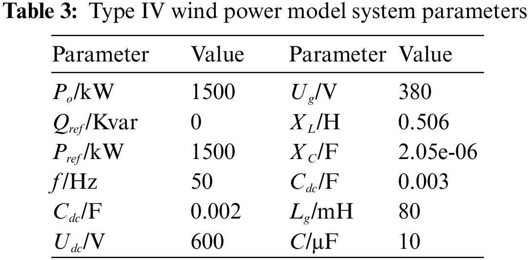
The system model shown in Fig. 8 is built in MATLAB/Simulink, and the system parameters are shown in Table 3. The main validation in this paper is the effectiveness of the suppression strategy so that the natural variation in wind speed is not reflected.
The improved control block diagram is shown in Fig. 9. The wind turbine system is connected to the power grid through a power electronic converter. The MSC is generally used to control the maximum output power, and the GSC is used to control the DC bus voltage. Currently, converters are mainly vector controlled in the dq coordinate system. However, due to the coupling terms related to the system parameters in the decoupling process, the vector control method is sensitive to the changes in grid LCL filter system parameters. VSG control can be well applied to the back-to-back converter. The converter on the wind turbine side absorbs power from the permanent magnet synchronous generator (PMSG) and feeds it into the DC bus, so that it can operate in virtual synchronous motor (VSM) mode. Different from the vector control, the synchronous converter control strategy does not depend on the parameters of the PMSG, so it can improve the system’s performs well. The VSG algorithm is used to control the Type IV WTGs.
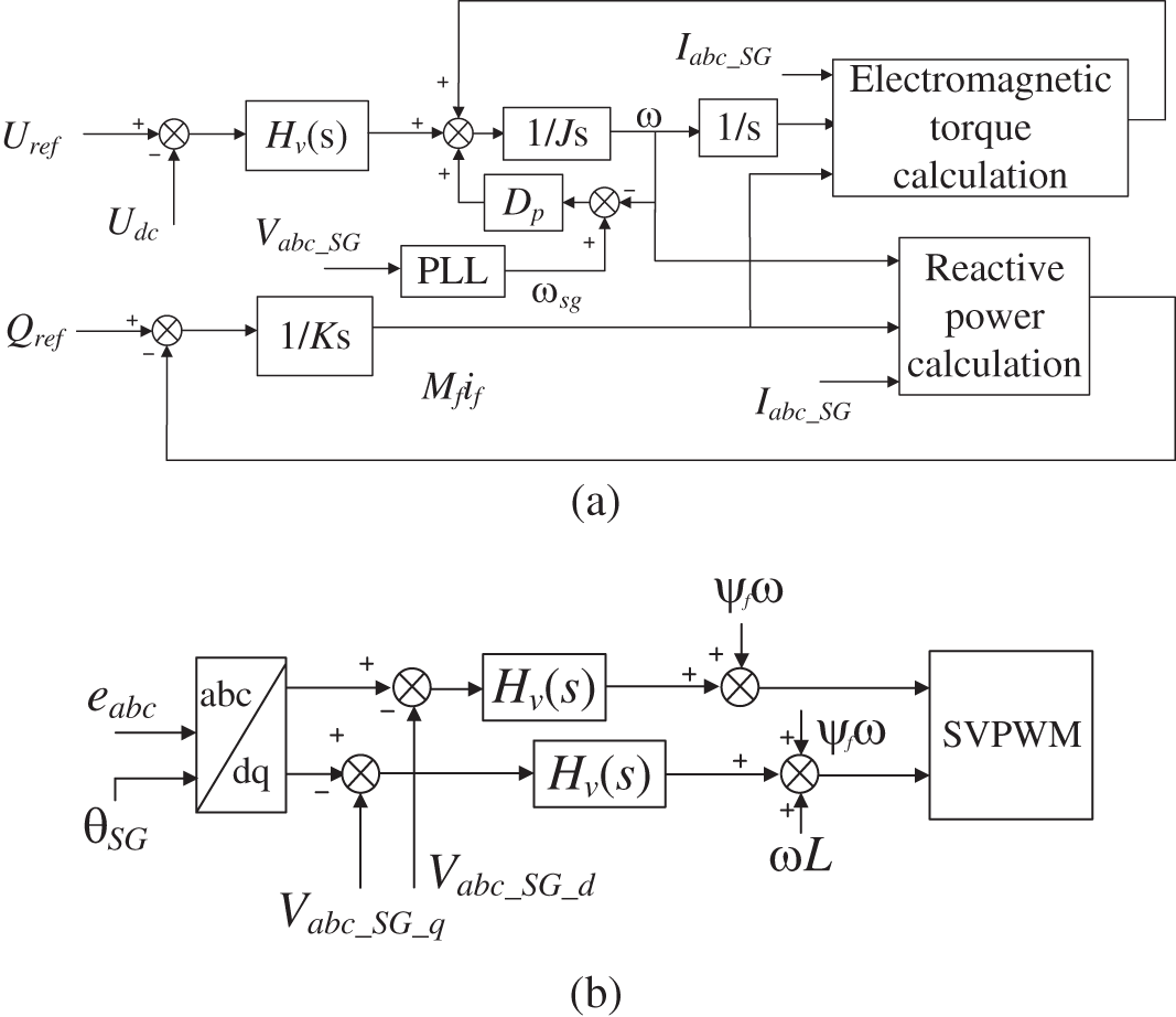
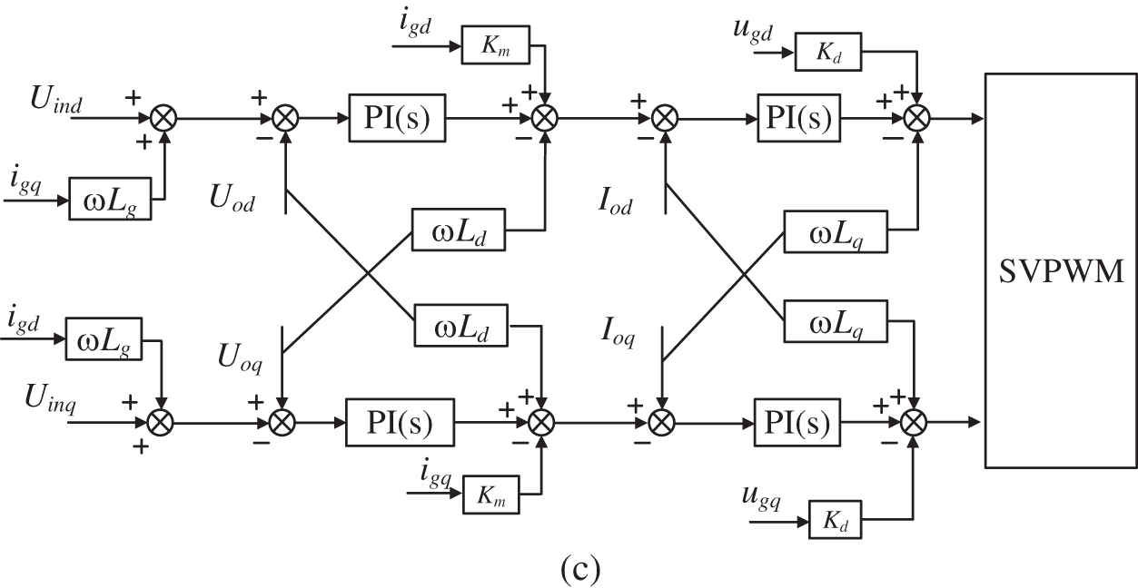
Figure 9: 9 VSG control block diagram. (a) DC voltage regulation control (b) voltage control (c) improved voltage and current double loop
The voltage and current of the system simulation are shown in Fig. 10. The system is connected to the grid through the PLL at 1 s, and the power oscillation at the subsynchronous frequency occurs. Fig. 10a shows that the voltage occurs SSO within 1.45–1.5 s after grid connection, and gradually converges. During the occurrence of SSO, the waveform is seriously distorted. In the weak grid environment, the current contains a large number of harmonics, and the wave distortion is 14.36%.
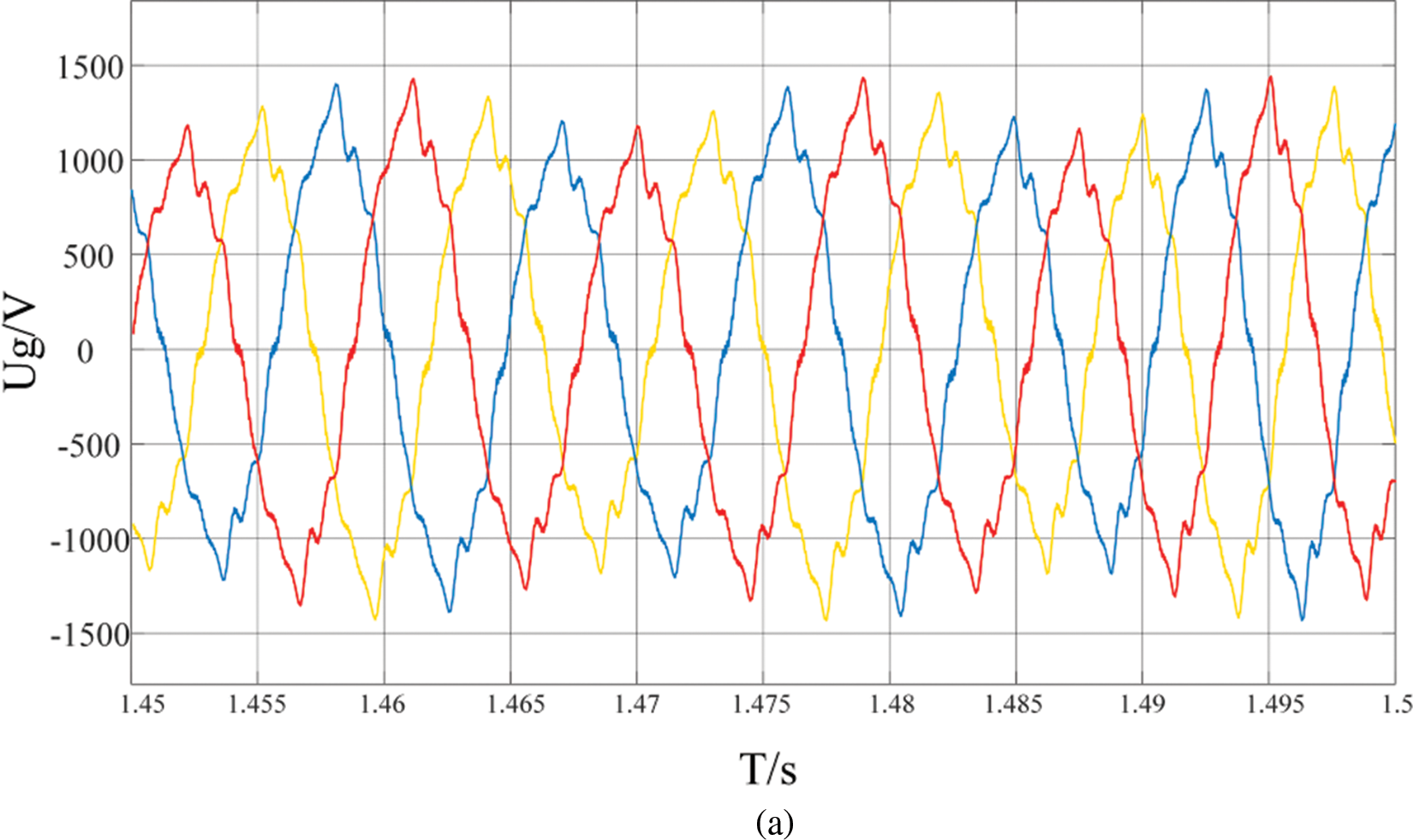
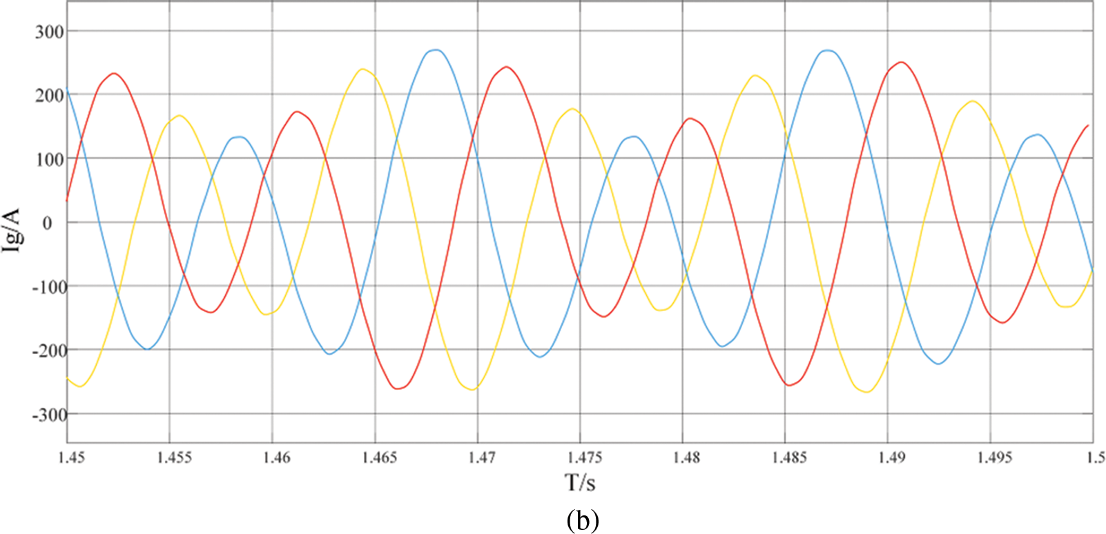
Figure 10: Grid-connected waveform. (a) voltage (b) current
Fig. 11 shows the grid integration of active and reactive power. From Fig. 11a, it can be seen that the active power has a large shock at grid connection, after which there is a periodic oscillation around 0, after which it slowly converges, but the oscillation time is long. From Fig. 11b, it can be seen that reactive power has a shock at 0.5 s. After that, the reactive power is negative, indicating that the grid is absorbing capacitive reactive power. At this time, the grid is capacitive and will form coupling with the grid inductance. This causes oscillation and affects the stability of the system.
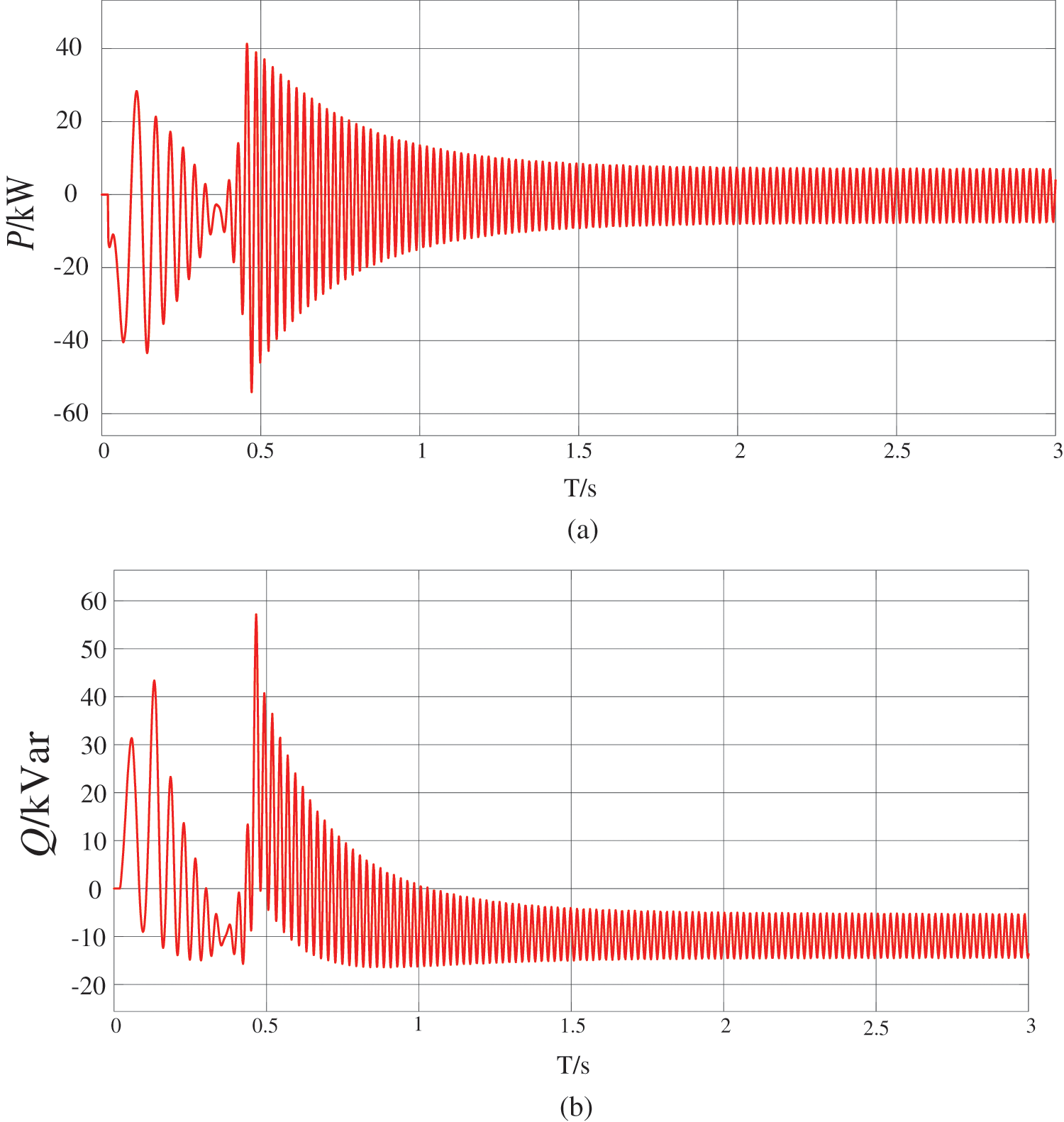
Figure 11: Oscillation power waveform. (a) active power (b) reactive power
Mainly to stabilize the DC voltage, DC voltage stabilization control was added at the front end of the active control link. The impact of DC voltage disturbance was fatal for the grid side, meanwhile, we modelized the active link of VSG to design the active power control and introduced the sag factor and rotational inertia as a way to stabilize the system.
The electromagnetic effect of the synchronous motor was taken into account in the reactive link and introduced the excitation current Mfif as a way to better simulate the operating characteristics of the SG. The reactive voltage sag factor is introduced to give the turbine side the ability to stabilize in case of faults.
The unimproved control strategy is unable to balance the coupling of the RSC and GSC voltage and current loop dq axes. The original controls did not take into account the grid voltage and current too, resulting in large grid current harmonics. To balance the dq axis voltage and current, the control algorithm shown is adopted on the grid side.
To verify the effectiveness of the control method, the voltage and current control are built in MATLAB/Simulink as shown in Fig. 9. The rest of the simulation conditions are the same.
The active power and reactive power are obtained as shown in Fig. 12. It can be seen that before 0.3 s, the power will still oscillate with amplitude reaching 500 kW. After 0.3 s, the system gradually stabilizes and the power fluctuates slightly.
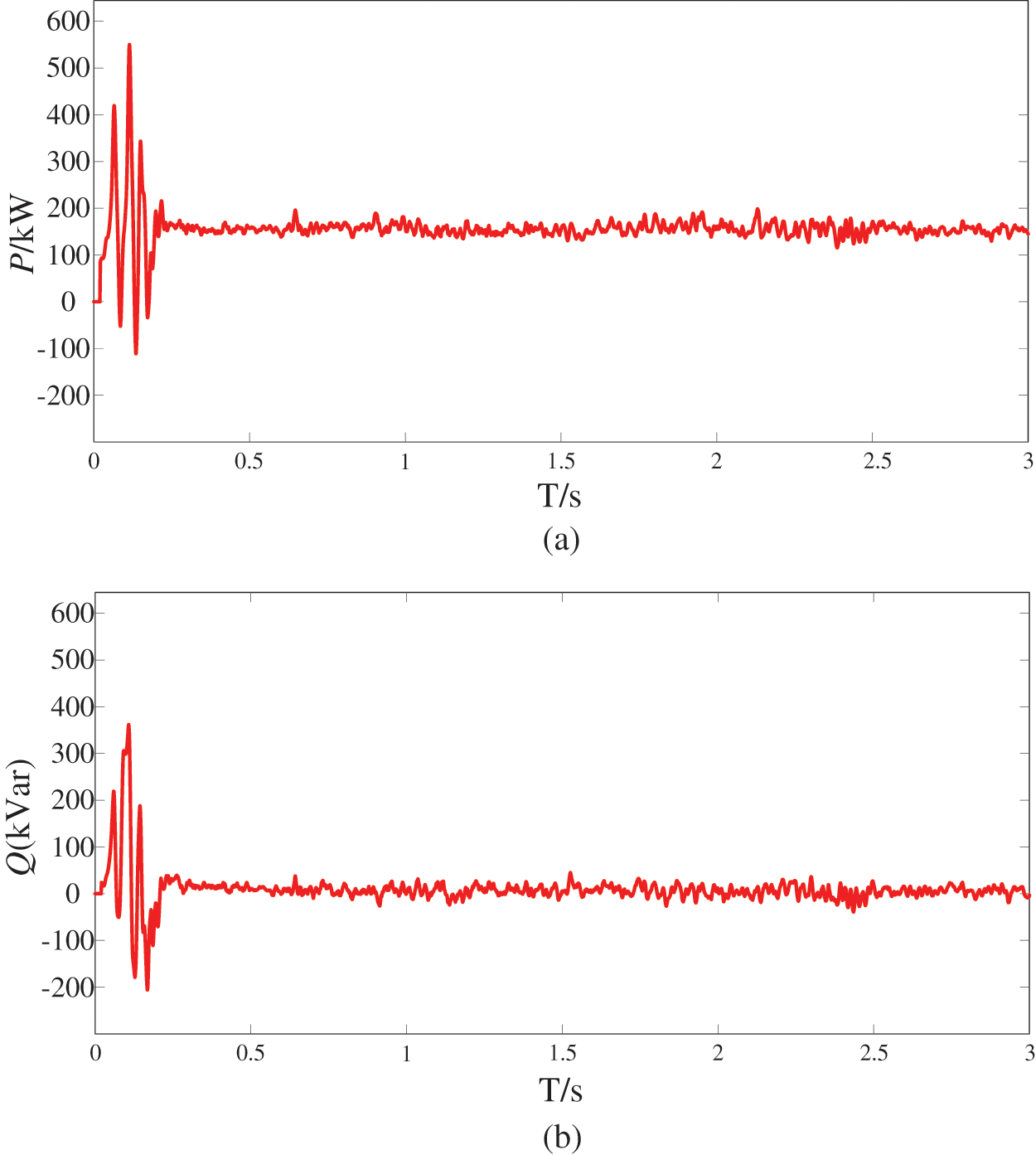
Figure 12: Power with improved control. (a) active power (b) reactive power
Fig. 13 shows the improved voltage waveform. The system operates in a very weak grid (SCR = 1.615) before 1.5 s, and the system has SSO that lasts for nearly 1 s, thus the grid voltage contained a large number of harmonics. The total harmonic of the wave distortion rate reached 13.67%, and then the waveform gradually approached the sine wave, and the system gradually stabilized. Afterwards, the system was operated under a weak grid (SCR = 2.15). It can be seen that the improved control method has a significant suppression effect on the SSO in the weak grid and can effectively suppress the harmonics of the grid voltage. Moreover, the harmonic distortion rate is 0.02%. As shown in Fig. 14. When the system is under normal strength (SCR = 4.6), due to the decrease in line impedance, the amplitude of grid voltage increases, which can meet the requirements of grid connection.
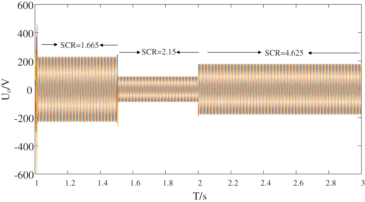
Figure 13: Voltage with improved control
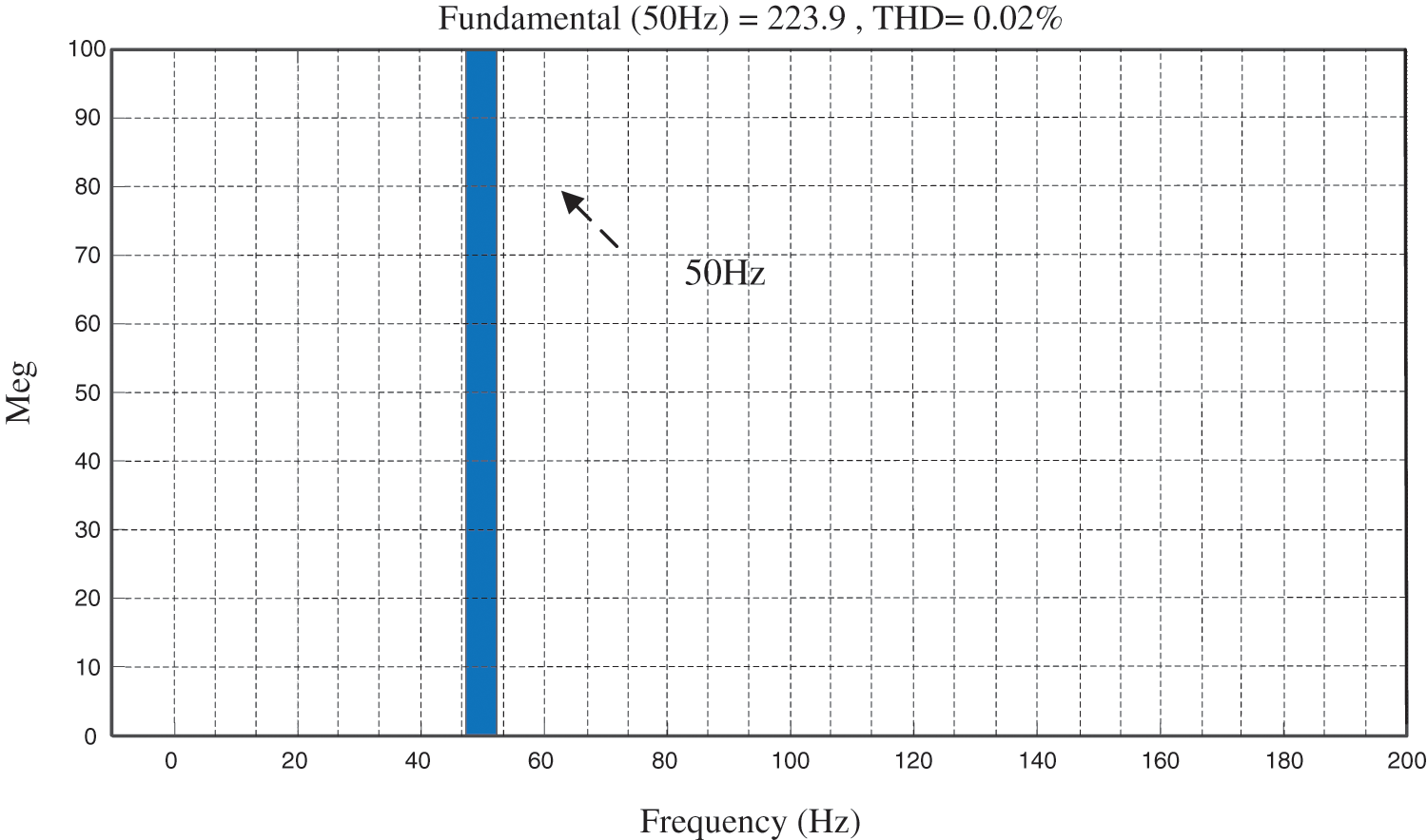
Figure 14: FFT analysis of voltage
In this paper, a Type IV WTG is built to interconnect the system with the grid. The frequency-coupled impedance model of the VSG and VSG are developed by using impedance analysis methods. Improvements are made to the voltage and current dual loop to balance the dq component coupling. The control parameters of the VSG are analyzed and compared. The influence of the rotational inertia J and the voltage factor K on the system is investigated. It was found that:
(1) The turbine-side section is controlled by VSG with the addition of a voltage regulator module. Modification of PLL control parameters usually has a limited effect on the system impedance.
(2) For double closed-loop systems,
(3) The unbalanced double closed-loop system generates currents and voltages containing a large number of harmonics. The control strategy investigated is to add the grid voltage dq component to the GSC side for modulation. At the same time, the current inner loop is coupled in the dq axis in a balanced manner. This suppression strategy provides a good solution for the effect of SSO on grid connection, which can effectively suppress the effect of sub-synchronous frequency and reduce the harmonics of grid voltage and current.
The goal of this paper is to analyze and suppress SSO in weak grids, but the interaction between sub/super-synchronous and low frequency oscillations can be found in many fields today. Because of the above situation, research and analysis are still critical and urgent. This includes the impact of distributed power plants at different locations and the adaptive regulation of control systems.
Acknowledgement: None.
Funding Statement: The author received no specific funding for this study.
Author Contributions: The authors confirm contribution to the paper as follows: study conception and design: Chongyang Zhao; data collection: Lin Chen; analysis and interpretation of results: Chongyang Zhao, Wei Chai, Beibei Rui; draft manuscript preparation: Wei Chai. All authors re viewed the results and approved the final version of the manuscript.
Availability of Data and Materials: The authors confirm that the data supporting the findings of this study are available within the article and/or its supplementary materials.
Conflicts of Interest: The authors declare that they have no conflicts of interest to report regarding the present study.
References
1. National Bureau of Statistics (2020). Statistical bulletin of national economic and social development. www.stats.gov.cn/sj/zxfb/202302/t20230228_1919011.html [Google Scholar]
2. Wu, H., Ruan, X. B., Yang, D. S., Chen, X. R., Zhao, W. X. et al. (2016). Small-signal modeling and parameters design for virtual synchronous generators. IEEE Transactions on Industrial Electronics, 63(7), 4292–4303. [Google Scholar]
3. Shintai, T., Miura, Y., Ise, T. (2014). Oscillation damping of a distributed generator using a virtual synchronous generator. IEEE Transactions on Power Delivery, 29(2), 668–676. [Google Scholar]
4. Liu, J., Miura, Y., Ise, T. (2016). Comparison of dynamic characteristics between virtual synchronous generator and droop control in inverter-based distributed generators. IEEE Transactions on Power Electronics, 31(5), 3600–3611. [Google Scholar]
5. Fathi, A., Shafiee, Q., Bevrani, H. (2018). Robust frequency control of microgrids using an extended virtual synchronous generator. IEEE Transactions on Power Systems, 33(6), 6289–6297. [Google Scholar]
6. Zhong, Q. C., Phi-Long, N., Ma, Z. Y., Sheng, W. X. (2014). Self-synchronized synchronverters: Inverters without a dedicated synchronization unit. IEEE Transactions on Power Electronics, 29(2), 617–630. [Google Scholar]
7. Wang, F., Zhang, L. J., Feng, X. Y., Guo, H. (2018). An adaptive control strategy for virtual synchronous generator. IEEE Transactions on Industry Applications, 54(5), 5124–5133. [Google Scholar]
8. Damas, R. N., Son, Y., Yoon, M., Kim, S. Y., Choi, S. (2020). Subsynchronous oscillation and advanced analysis: A review. IEEE Access, 8, 224020–224032. [Google Scholar]
9. Xiao, X. N., Zhang, J., Gao, B. F., Wu, Y. S., Luo, C. et al. (2013). Simulation and study on mitigation measures of frequent subsynchronous oscillation with low amplitude at multi-power plants. Science China Technological Sciences, 56(10), 1340–1353. [Google Scholar]
10. Luiz, A. S. P., Willis, F. L., Abdel-Aty, E. (2001). Basic mechanisms of control interactions among power electronic-assisted power systems. IEEE/PES Transmission and Distribution Conference and Exposition. Developing New Perspectives, 1, 397–402. [Google Scholar]
11. Liu, H. K., Xie, X. R., He, J. B., Xu, T., Yu, Z. et al. (2017). Subsynchronous interaction between direct-drive PMSG based wind farms and weak AC networks. IEEE Transactions on Power Systems, 32(6), 4708–4720. [Google Scholar]
12. Shair, J., Xie, X. R., Li, Y. H., Terzija, V. (2021). Hardware-in-the-loop and field validation of a rotor-side subsynchronous damping controller for a series compensated DFIG system. IEEE Transactions on Power Delivery, 36(2), 698–709. [Google Scholar]
13. Guo, J., Chen, Y. D., Wang, L., Wu, W. H., Wang, X. Y. et al. (2021). Impedance analysis and stabilization of virtual synchronous generators with different DC-link voltage controllers under weak grid. IEEE Transactions on Power Electronics, 36(10), 11397–11408. [Google Scholar]
14. Rafique, Z., Khalid, H. M., Muyeen, S. M., Kamwa, I. (2022). Bibliographic review on power system oscillations damping: An era of conventional grids and renewable energy integration. International Journal of Electrical Power & Energy Systems, 136, 107556. [Google Scholar]
15. Yuan, Q., Wen, X., Li, W., Renbo, W., Hao, L. et al. (2020). Subsynchronous oscillation monitoring and alarm method based on phasor measurements. Global Energy Interconnection, 3(5), 464–474. [Google Scholar]
16. Abdeen, M., Li, H., Jing, L. (2020). Improved subsynchronous oscillation detection method in a DFIG-based wind farm interfaced with a series-compensated network. International Journal of Electrical Power & Energy Systems, 119(1), 105930. [Google Scholar]
17. Farahani, M. (2012). A new control strategy of SMES for mitigating subsynchronous oscillations. Physica C: Superconductivity, 483, 34–39. [Google Scholar]
18. Gil-Gonzalez, W., Montoya, O. D., Garces, A. (2018). Control of a SMES for mitigating subsynchronous oscillations in power systems A PBC-PI approach. Journal of Energy Storage, 20, 163–172. [Google Scholar]
19. Haris, M. K., Farid, F., Magdi, S. M., Mutaz, H. (2023). Wide area monitoring system operations in modern power grids: A median regression function-based state estimation approach towards cyber attacks. Sustainable Energy, Grids and Networks, 34, 101009. [Google Scholar]
20. Li, P., Xiong, L., Ma, M., Huang, S., Zhu, Z. (2022). Energy-shaping L2-gain controller for PMSG wind turbine to mitigate subsynchronous interaction. International Journal of Electrical Power & Energy Systems, 135, 0142–0615. [Google Scholar]
21. Li, P., Xiong, L., Ma, M., Huang, S., Zhu, Z. (2022). Energy-shaping L2-gain controller for PMSG wind turbine to mitigate subsynchronous interaction. International Journal of Electrical Power & Energy Systems, 135, 0142–0615. [Google Scholar]
22. Kumar, S., Kumar, N., Jain, V. (2012). Comparison of various auxiliary signals for damping subsynchronous oscillations using TCR-FC. Energy Procedia, 14, 695–701. [Google Scholar]
23. Ghorbani, A., Pourmohammad, S. (2011). A novel excitation controller to damp subsynchronous oscillations. International Journal of Electrical Power & Energy Systems, 33(3), 411–419. [Google Scholar]
24. Liu, Y. Q., Zheng, J. Y., Chen, Q. C., Duan, Z. Y., Tian, Y. H. et al. (2022). MMC-STATCOM supplementary wide-band damping control to mitigate subsynchronous control interaction in wind farms. International Journal of Electrical Power & Energy Systems, 141, 108171. [Google Scholar]
25. Li, G. X., Chen, Y. D., Luo, A., Wang, Y. C. (2021). An inertia phase locked loop for suppressing sub-synchronous resonance of renewable energy generation system under weak grid. IEEE Transactions on Power Systems, 36(5), 4621–4631. [Google Scholar]
26. Fan, L. L., Miao, Z. X. (2018). Wind in weak grids: 4 Hz or 30 Hz oscillations? IEEE Transactions on Power Systems, 33(5), 5803–5804. [Google Scholar]
27. Li, Y., Fan, L. L., Miao, Z. X. (2020). Wind in weak grids: Low-frequency oscillations, subsynchronous oscillations, and torsional interactions. IEEE Transactions on Power Systems, 35(1), 109–118. [Google Scholar]
28. Khalid, H. M., Peng, J. C. H. (2016). Tracking electromechanical oscillations: An enhanced maximum-likelihood based approach. IEEE Transactions on Power Systems, 31(3), 1799–1808. [Google Scholar]
29. Khalid, H. M., Peng, J. C. H. (2015). Improved recursive electromechanical oscillations monitoring scheme: A novel distributed approach. IEEE Transactions on Power Systems, 30(2), 680–688. [Google Scholar]
30. Wu, X., Xu, S. S., Shi, X. Y., Shahidehpour, M., Wang, M. T. et al. (2023). Mitigating subsynchronous oscillation using model-free adaptive control of DFIGs. IEEE Transactions on Sustainable Energy, 14(1), 242–253. [Google Scholar]
31. Yang, S. H., Shen, R. X., Shu, J., Zhang, T., Li, Y. J. (2022). PLL based sub-/super-synchronous resonance damping controller for D-PMSG wind farm integrated power systems. IEEE Transactions on Energy Conversion, 37(4), 2370–2384. [Google Scholar]
32. Shair, J., Xie, X. R., Yang, J. J., Li, J. Y., Li, H. Z. (2022). Adaptive damping control of subsynchronous oscillation in DFIG-based wind farms connected to series-compensated network. IEEE Transactions on Power Delivery, 37(2), 1036–1049. [Google Scholar]
33. Verma, P., Seethalekshmi, K., Dwivedi, B. (2022). A self-regulating virtual synchronous generator control of doubly fed induction generator-wind farms. IEEE Canadian Journal of Electrical and Computer Engineering, 46(1), 35–43. [Google Scholar]
34. Mohammed, N., Meng, K., Xiao, W. D., Al-Durra, A., Dong, Z. Y. (2023). Online grid impedance estimation-based adaptive control of virtual synchronous generators considering strong and weak grid conditions. IEEE Transactions on Sustainable Energy, 14(1), 673–687. [Google Scholar]
35. Ambia, M. N., Meng, K., Xiao, W. D., Al-Durra, A., Dong, Z. Y. (2021). Interactive grid synchronization-based virtual synchronous generator control scheme on weak grid integration. IEEE Transactions on Smart Grid, 13(5), 4057–4071. [Google Scholar]
36. Zhang, X. Y., Liu, H. Z., Fu, Y., Li, Y. G. (2022). Virtual shaft control of DFIG-based wind turbines for power oscillation suppression. IEEE Transactions on Sustainable Energy, 13(4), 2316–2330. [Google Scholar]
37. Zhang, F., Li, J. X., Liu, J., Gao, W. Z., He, J. G. (2023). An improved interpolated DFT-based parameter identification for sub-/super-synchronous oscillations with synchrophasors. IEEE Transactions on Power Systems, 38(2), 1714–1727. [Google Scholar]
38. Xue, T., Lyu, J., Wang, H., Cai, X., Li, J. Y. et al. (2020). A complete impedance model of a PMSG-based wind turbine system considering machine-side dynamics. The 46th Annual Conference of the IEEE Industrial Electronics Society, Singapore. [Google Scholar]
39. Shi, K., Wang, Y., Sun, Y. X., Xu, P. F., Gao, F. (2021). Frequency-coupled impedance modeling of virtual synchronous generators. IEEE Transactions on Power Systems, 36(4), 3692–3700. [Google Scholar]
40. Liu, H. C., Sun, J. (2014). Voltage stability and control of offshore wind farms with AC collection and HVDC transmission. IEEE Journal of Emerging and Selected Topics in Power Electronics, 2(4), 1181–1189. [Google Scholar]
41. Shu, D. W., Xie, X. R., Rao, H., Gao, X. D., Jiang, Q. R. et al. (2018). Sub- and super-synchronous interactions between STATCOMs and weak AC/DC transmissions with series compensations. IEEE Transactions on Power Electronics, 33(9), 7424–7437. [Google Scholar]
where
Cite This Article
 Copyright © 2023 The Author(s). Published by Tech Science Press.
This work is licensed under a Creative Commons Attribution 4.0 International License , which permits unrestricted use, distribution, and reproduction in any medium, provided the original work is properly cited.
 Downloads
 Citation Tools