
 Submit a Paper
 Propose a Special lssue
 Open Access
ARTICLE

Title Supersonic Condensation and Separation Characteristics of CO2-Rich Natural Gas under Different Pressures
1 Engineering Management Center, Sinopec Shengli Oilfield Company, Dongying, 257000, China
2 Technical Inspection Center, Sinopec Shengli Oilfield Company, Dongying, 257000, China
3 Shandong Provincial Key Laboratory of Oil & Gas Storage and Transportation Safety, College of Pipeline and Civil Engineering, China University of Petroleum, Qingdao, 266580, China
* Corresponding Author: Weijia Dong. Email:
(This article belongs to the Special Issue: Multiphase Flow Theory in Oil and Gas Gathering and Transportation Process)
Energy Engineering 2023, 120(2), 529-540. https://doi.org/10.32604/ee.2023.022765
Received 24 March 2022; Accepted 07 June 2022; Issue published 29 November 2022
 View Full Text
 Download PDF
Abstract
Supersonic separation technology is a new natural gas sweetening method for the treatment of natural gas with high CO2 (carbon dioxide) content. The structures of the Laval nozzle and the supersonic separator were designed, and the mathematical models of supersonic condensation and swirling separation for CO2-CH4 mixture gas were established. The supersonic condensation characteristics of CO2 in natural gas and the separation characteristics of condensed droplets under different inlet pressures were studied. The results show that higher inlet pressure results in a larger droplet radius and higher liquid phase mass fraction; additionally, the influence of centrifugal force is more pronounced, and the separation efficiency and removal efficiency of CO2 are higher. When the inlet pressure is 6 and 9 MPa, the liquefaction efficiency at the Laval nozzle outlet increases from 56.90% to 79.97%, and the outlet droplet radius increases from 0.39 to 0.72 μm, and the removal efficiency is 31.25% and 54.52%, respectively. The effects of inlet pressures on the removal efficiency of the supersonic separator are complicated and are controlled by the combined effects of liquefaction capacity of the nozzle and centrifugal separation capacity of the swirl vane.Keywords
Nomenclature
| CD | drag coefficient (–) |
| DT | thermophoresis coefficient (–) |
| dl | droplet size (m) |
| dij | deformation rate tensor (–) |
| E | total energy (J/kg) |
| F | force between the droplet and the surrounding gas (N) |
| FD | drag force per unit mass of particles (N) |
| FO | other forces (N) |
| FS | Saffman lift force |
| FT | thermophoretic force (N) |
| J | spontaneous nucleation rate (m3/s) |
| h | total enthalpy of gas (J/kg) |
| hlv | latent heat of condensation (J/kg) |
| keff | effective thermal conductivity (W/(m·K)) |
| l1 | length of the convergent section (mm) |
| M | mole fraction of CO2 (–) |
| ml | droplet mass (kg) |
| mv | mass of condensed liquid per unit volume per unit time (kg/(m3·s)) |
| N | droplet number (1/kg) |
| p | pressure of the mixed gas (Pa) |
| pin | inlet pressure (MPa) |
| Re | relative Reynolds number (–) |
| r0 | inlet radius of convergent section (mm) |
| rcr | outlet radius of convergent section (throat) (mm) |
| rd | droplet radius (m) |
| Sh | energy source term (J/(m3·s)) |
| Sm | mass source term (kg/(m3·s)) |
| Su | momentum source term (kg/(m2·s2)) |
| SY | humidity source term (kg/(m3·s)) |
| T | temperature of mixture gas (K) |
| Tin | inlet temperature (K) |
| ul | droplet velocity (m/s) |
| ui | axial velocity components (m/s) |
| uj | radial velocity components (m/s) |
| u’i | axial velocity fluctuations (m/s) |
| u’j | radial velocity fluctuations (m/s) |
| Vl | droplet volume (m3) |
| Y | liquid phase mass fraction (–) |
| Y/Yin | nozzle fluidization efficiency (–) |
| Greek Symbols | |
| δ | Kronecker delta number (–) |
| η′ | removal efficiency of supersonic separator (–) |
| η | separation efficiency (–) |
| μ | dynamic viscosity of the mixed gas ((N·s)/m) |
| ν | dynamic viscosity (Pa·s) |
| ρl | droplet density (kg/m3) |
| ρg | gas density (kg/m3) |
| ρl | density of liquid phase (kg/m3) |
| ρ | mixture phase density (kg/m3) |
| ρv | density of mixed gas (kg/m3) |
| τeff | effective stress tensor (–) |
| Subscripts | |
| 0, 1 | component |
| i, j | x, y-axis |
| l | liquid phase |
| g | gas-phase |
| v | vapor phase |
| Abbreviations | |
| CFD | Computational Fluid Dynamics |
| ICCT | Internal Consistent Classical Nucleation Theory |
| UDF | User Defined Function |
In recent years, with the optimization and upgrading of world's energy structure, natural gas has become more and more critical in the economic fields. More and more countries have proposed accelerating the pace of structural adjustments, increasing the proportion of natural gas consumption and expanding the natural gas consumption market [1–3]. Besides hydrocarbons, natural gas from wellheads often contains excessive CO2 (carbon dioxide) and other non-hydrocarbon gases. The presence of CO2 will reduce the natural gas calorific value and pipeline transportation capacity, and at the same time, it will cause severe corrosion of facilities and pipelines. Moreover, CO2 can form dry ice and block the pipeline at low temperatures. Thus, CO2 removal during natural gas processing is one of the key processes [4]. Currently, CO2 removal methods commonly used in the industry mainly contain chemical absorption, pressure swing adsorption, physical adsorption, and membrane separation. These methods have achieved CO2 removal to a certain extent. Still, at the same time, there are some problems such as high energy consumption, low removal efficiency, high investment cost, and large loss of hydrocarbon gas [5–7].
Supersonic separation technology is an emerging natural gas treatment technology which combines expansion refrigeration with swirling separation. In a separator, the swirling motion is generated by a swirl generation device. Natural gas expands to supersonic velocities in the Laval nozzle, resulting in low pressure and temperature. The nucleation and condensation of impure gases occur, and the impure gas begins to change into droplets. Then the liquid droplets are centrifuged onto the walls and removed from the gas mixtures. Compared with traditional processes, it has many advantages, such as being a compact structure, energy-saving, and environmentally protective innocation, of which is, widely used in natural gas dehydration [8,9] and liquefaction today [10,11].
Relevant scholars have carried out a lot of research work on the above technologies. Jassim et al. [12,13] adopted CFD technology to simulate the flow of high-pressure natural gas in Laval nozzles. They analyzed the effects of swirl strength, nozzle structure, and real gas effects on the flow characteristics. Malyshkina [14,15] used the Eulerian two-dimensional model to study the fluid flow characteristics in the supersonic separator, discussed the effects of aerodynamic shock waves on the supersonic flow field, and analyzed the influence of Mach number on the volume and composition of natural gas condensate and stress recovery ability. Ma et al. [16] developed a cone-core supersonic swirling separation device and set up an experimental platform to conduct performance tests with water and ethanol vapor as the medium. Lun et al. [17] conducted a numerical simulation study on the nonequilibrium condensation phase change law of water vapor during supersonic flow. Shooshtari et al. [18] established a two-component condensation theoretical model based on the mass transfer rate and applied the model to the simulation calculation of supersonic condensation of water vapor. Wen et al. [19] conducted field tests using a new type of natural gas supersonic dehydration device. The results show that the energy loss can be minimized through an overall optimization design. It can also reduce the power consumption of the refrigeration compressor by 50%–70% compared with the low-temperature process of propane refrigeration under the condition of the same condensate yield. Bian et al. [20,21] proposed a theoretical model for the supersonic condensation of natural gas mixtures; the condensation process of the methane-ethane mixture can be divided into four main stages in Bian’s model. This model reveals the supersonic condensation process of the mixture from a microcosmic point of view, laying a foundation for the study of the condensation of multi-component alkane mixtures. In addition, the influence of swirl on the supersonic condensation and liquefaction characteristics of natural gas was systematically studied [22].
As a supplement and improvement to the traditional natural gas purification process, Bian et al. [23,24] put forward applying the supersonic separation technology to the field of CO2 removal in the first place. However, up to now, the complex problems of condensation and cyclone separation in the process of supersonic CO2 removal are still well understood. In this paper, the condensation efficiency and removal efficiency of CO2 in supersonic separators under different pressure conditions were studied, which is of great significance to improving and developing the natural gas purification process and reduce the cost of gas field development.
2 Structure Design of the Nozzle and Supersonic Separator
Laval nozzle is the key part of realizing CO2 condensation in supersonic separator. In order to obtain a more uniform flow field, the convergent section adopts the Vitosinski curve [25,26], and the parameters are selected as follows: r0 = 40 mm, rcr = 5 mm, and l1 = 140 mm; the convergent section curve satisfies the following equation:
For the divergent section of the nozzle, so as to predigest the design process and realize expansion and rectification at the same time, considering the characteristics of each linear comprehensively, the straight-line method is adopted to take the shape of a cone. And the line type of the divergent section satisfies the equation [27]:
In order to ensure that the airflow is evenly accelerated to the sonic speed and to prevent the sudden change of the flow area from causing instability of the airflow, a continuous and gradual curve connection is used at the nozzle throat to get a smooth transition.
The structure and location of the cyclone should meet the separation requirements, as well as coordinates with other units in the separator. The design method in the reference adopts a rotating vane structure; the thickness and the length of the vane are 0.5 and 10 mm, respectively, and the rotation angle is 90 degrees, the swirl vane is set at the rear of the divergent rectification section, 350 mm from the inlet. The lengths of each section are shown in Fig. 1.
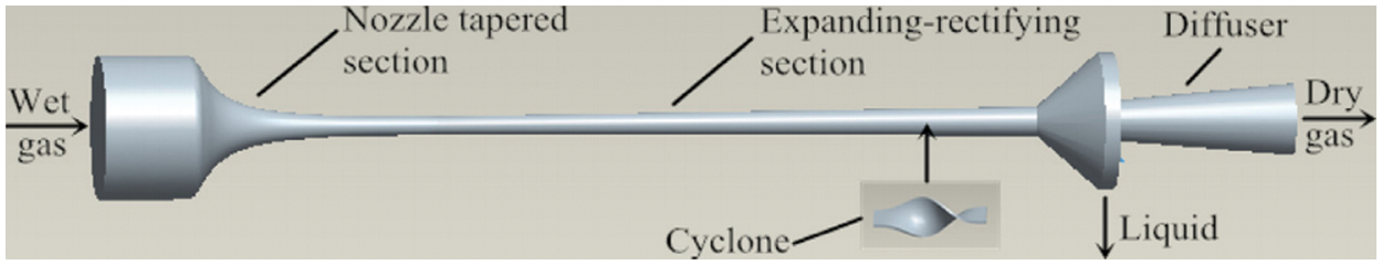
Figure 1: Structure diagram of the supersonic separator
Based on the component transport equation of two-component fluid, the governing equations are established respectively. The gas-phase flow governing equations include mass equations, momentum equations, and energy equations. In contrast, the liquid-phase equation consists of the conservation equation for the droplet number and the relation between the parameters related to nucleating flow [28,29].
The gas-phase governing equations:
The liquid-phase governing equations:
3.2 Calculation Equation of Nucleation and Droplet Growth
The condensation of CO2 gas mainly contains two processes: nucleation and droplet growth. The calculation formula of the nucleation process adopts the ICCT model. This model revised the free energy calculation formula based on previous studies. The expression form of the ICCT model has been listed in the references [30,31].
After the nucleation process is finished, the droplets begin to grow continuously. The heat transfer coefficient of a droplet in steam is in connection with the size of the droplet and the relative velocity of the droplet in the steam molecule. The growth model of droplets proposed by Gyarmathy is used to calculate the droplet growth rate [32,33].
3.3 Equations of Droplet Discrete Phase Motion
The discrete phase motion equation of a CO2 droplet is as follows:
Due to the high velocity of the droplet in the swirling process, its centrifugal force far outweighs its own gravity, so the gravity term is ignored in the numerical simulation. Meanwhile, because the gas density is much less than the droplet density, the buoyancy of the droplet is ignored. The simplified discrete phase motion equation is as follows:
The expression of FD is as follows [34]:
The other forces FO mainly consider the effects of FT and FS. The expressions of these two forces are as follows [35]:
where, Kk = 2.584.
3.4 Meshing and Boundary Conditions
The ANSYS FLUENT 16.0 software is adopted to simulate the CO2 supersonic condensation and separation processes. The Laval nozzle (two-dimensional) and the supersonic separator (three-dimensional) have meshed separately, and the boundary layer mesh is encrypted. In terms of the supersonic conditions, the inlet boundary and outlet conditions are set to be inlet pressure boundary and outlet pressure boundary, respectively. The time step is 10-6 in the numerical simulation. The convergence criterion is 10-6 for the energy equation and 10-3 for all other equations [36].
The grid independence was verified based on the above numerical calculation method. The grid numbers of the Laval nozzle and the supersonic separator were determined to be 15,410 and 281,095, respectively.
4.1 Condensation Efficiency of CO2 in Laval Nozzle under Different Pressures
So as to study the CO2 condensation in Laval nozzle under different pressure conditions, Tin = 273.15 K and M = 0.2 were kept unchanged. The pin was set to be 6, 7, 8, and 9 MPa, respectively. The effects of inlet pressure on condensation parameters were analyzed. The variation law of condensation parameters (nucleation rate and droplet radius) under different pressure conditions was obtained by numerical simulation.
As shown in Fig. 2, it shows that when Tin is 273.15 K and M is 20%, as the pin increases, the CO2 condensation position moves forward. When pin is 6 MPa, The condensation start position is at x = 143.27 mm, and when pin increases to 9 MPa, the position where the condensation occurs moves forward to x = 139.59 mm, because the reason is when pin increases, the partial pressure of CO2 steam also increases, the greater the degree of supersaturation, the greater the degree of expansion, and spontaneous condensation is possible to occur under the same temperature. After analyzing the variation of nucleation rate and droplet radius (Figs. 2 and 3), it can be concluded that as pin increases, the maximum CO2 nucleation rate gradually decreases, and the CO2 droplet radius gradually increases. This is because the higher the inlet pressure, the sooner the condensation occurs, the higher the temperature when condensation occurs, and the smaller the nucleation rate.
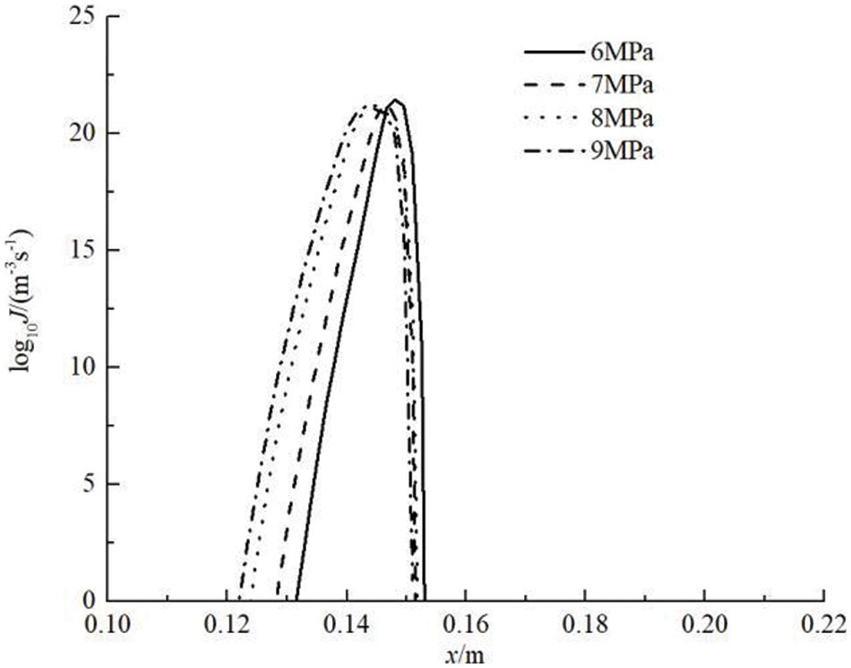
Figure 2: Nucleation rate distribution in the nozzle
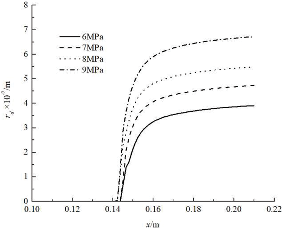
Figure 3: Droplet radius distribution in the nozzle
So as to study the effects of pin on liquefaction efficiency and droplet radius, the liquefaction efficiency at the outlet of the nozzle (the ratio of the liquid mass to CO2 mass at the inlet) and droplet radius were calculated under different pressures; the results can be seen in Fig. 4.
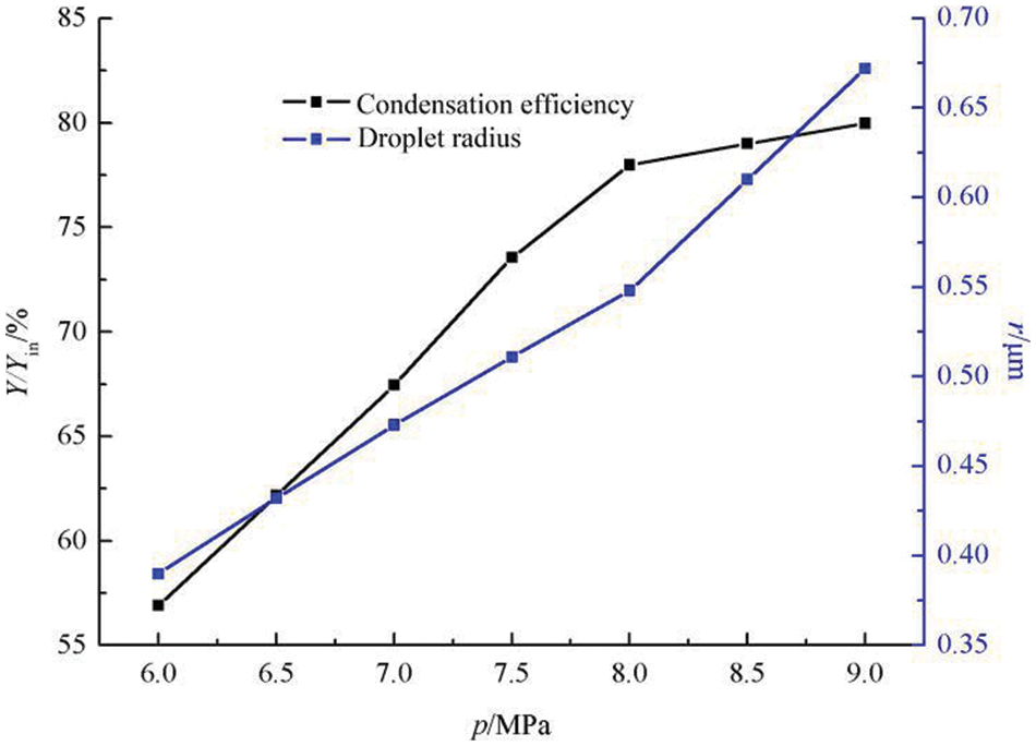
Figure 4: The effects of pin on the liquefaction efficiency and droplet radius of nozzle outlet
As shown in Fig. 4 under the same other conditions, the CO2 liquefaction efficiency at the nozzle outlet increases with the increase of pin. As pin increases from 6 to 9 MPa, the CO2 liquefaction efficiency at the Laval nozzle outlet increases from 56.90% to 79.97%, and the outlet droplet radius increases from 0.39 to 0.72 μm. When pin is smaller than 8 MPa, the increasing pin has particularly obvious effects on improving the liquefaction efficiency.
4.2 Effects of Inlet Pressure on Separation Efficiency
After the droplets are formed, the removal of CO2 is realized only if the separator wall captures them to form a liquid film and flow to the collector or collected directly by the sump. Therefore, in addition to the liquefaction efficiency, the separation efficiency is also an important index to evaluate if the separator structure is reasonable. During the separation process, part of the liquefied CO2 droplets enters the collecting tank (assumed as mtrap). In contrast, the remaining part flows out of the dry gas outlet without separation and is re-gasified (assumed as mescape). The separation efficiency η is defined as mtrap/mtotal.
Fig. 5 shows the separation efficiency under different pin conditions. It can be seen that the separation efficiency increases with the growth of the inlet pressure. When pin = 6 MPa, the separation efficiency of the supersonic separator is only 54.92%, while pin increases to 9 MPa, the supersonic separator's separation efficiency reaches 68.18%. This is because when pin is smaller, the diameter of the CO2 droplet and the centrifugal force is smaller. Most of the droplets are not captured by the wall due to the inertial effects caused by the axial velocity and are discharged with the gas. When the diameter of the CO2 droplet increases, the influence of centrifugal force is more apparent, and the droplet is more likely to be thrown to the wall and captured by the separator.
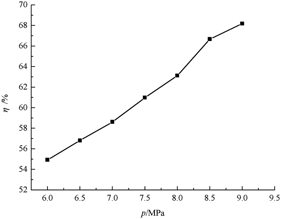
Figure 5: The effects of pin on the separation efficiency
4.3 Effects of Inlet Pressure on CO2 Removal Efficiency
The removal efficiency of CO2 in the supersonic separation process is determined by both nozzle condensation efficiency and swirl separation efficiency. Therefore, it is necessary to evaluate the removal efficiency of the supersonic separator by comprehensively considering the two. η′ is defined as Y/Yin multiplied by η.
According to the liquefaction efficiency and the separation efficiency under different inlet pressure conditions obtained in the above sections, the removal efficiency of the supersonic separator under corresponding conditions is calculated, and the results are shown in Fig. 6.
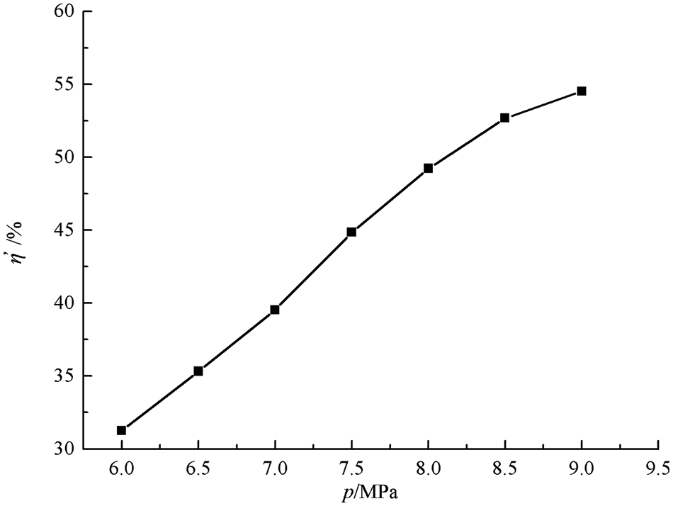
Figure 6: The effects of pin on the removal efficiency
As shown in Fig. 6, the inlet pressure affects the removal efficiency obviously, and the removal efficiency increases with the growth of the pin. When pin = 6 MPa, the CO2 removal efficiency is 31.25%, and when pin increases to 9 MPa, the CO2 removal efficiency can be as high as 54.52%. The effects of inlet pressures on the removal efficiency of supersonic separator are mainly reflected in two aspects: one is that pin affects the liquefaction efficiency of CO2 gas; The other is that the droplet size is different when CO2 gas condenses under different pin conditions, which means that the separation efficiency of droplet after passing through the swirl vane will be different. The combined effects of the two aspects lead to significant differences in the removal efficiency of CO2 gas under different pressure conditions.
In this paper, the supersonic condensation and swirling separation models were established. The supersonic condensation and separation characteristics of CO2-rich natural gas under different pressures were studied. The following conclusions can be drawn:
With the increase of inlet pressure, the position of condensation moves towards the nozzle inlet, the maximum nucleation rate decreases, and the droplet radius and liquid phase mass fraction increase. The CO2 liquefaction efficiency of the nozzle outlet increases with the growth of inlet pressure. The inlet pressure obviously affects the removal efficiency of the supersonic separator, and the removal efficiency increases with the growth of the inlet pressure.
The influence of inlet pressure on the removal efficiency of the supersonic separator is mainly reflected in two aspects: the inlet pressure affects the liquefaction efficiency of CO2 gas. The other is that the droplet size is different when CO2 gas condenses under different inlet pressure conditions, which means that the separation efficiency of the droplet after passing through the swirl vane will be different.
In the following research, the experimental research of supersonic condensation and separation characteristics of CO2 under different inlet pressure conditions can be carried out to verify the numerical simulation models and results to lay a foundation for the field application of the supersonic separation technology.
Funding Statement: This work was supported by the Research Project of Technical Inspection Center of Sinopec Shengli Oilfield Company “Research of Energy Flow Optimization Analysis and Application Technology of Oilfield Production System” and the Natural Science Foundation of Shandong Province (Grant No. ZR2021QE030).
Conflicts of Interest: The authors declare that they have no conflicts of interest to report regarding the present study.
References
1. Holz, F., Richter, P. M., Egging, R. (2015). A global perspective on the future of natural gas: Resources, trade, and climate constraints. Review of Environmental Economics & Policy, 9(1), 85–106. DOI 10.1093/reep/reu016. [Google Scholar] [CrossRef]
2. Scharf, H., Arnold, F., Lencz, D. (2020). Future natural gas consumption in the context of decarbonization-A meta-analysis of scenarios modeling the German energy system. Energy Strategy Reviews, 33, 100591. DOI 10.1016/j.esr.2020.100591. [Google Scholar] [CrossRef]
3. Bian, J., Yang, J., Li, Y. X., Chen, Z. Q., Liang, F. C. et al. (2021). Thermodynamic and economic analysis of a novel hydrogen liquefaction process with LNG precooling and dual-pressure Brayton cycle. Energy Conversion and Management, 250, 114904. DOI 10.1016/j.enconman.2021.114904. [Google Scholar] [CrossRef]
4. Faramawy, S., Zaki, T., Sakr, A. A. E. (2016). Natural gas origin, composition, and processing: A review. Journal of Natural Gas Science and Engineering, 34, 34–54. DOI 10.1016/j.jngse.2016.06.030. [Google Scholar] [CrossRef]
5. Scholes, C. A., Stevens, G. W., Kentish, S. E. (2012). Membrane gas separation applications in natural gas processing. Fuel, 96, 15–28. DOI 10.1016/j.fuel.2011.12.074. [Google Scholar] [CrossRef]
6. Koku, O., Perry, S., Kim, J. K. (2014). Techno-economic evaluation for the heat integration of vaporisation cold energy in natural gas processing. Applied Energy, 114, 250–261. DOI 10.1016/j.apenergy.2013.09.066. [Google Scholar] [CrossRef]
7. Cao, X. W., Bian, J. (2019). Supersonic separation technology for natural gas processing: A review. Chemical Engineering and Processing-Process Intensification, 136, 138–151. DOI 10.1016/j.cep.2019.01.007. [Google Scholar] [CrossRef]
8. Liu, Y., Cao, X. W., Yang, J., Li, Y. X., Bian, J. (2021). Energy separation and condensation effects in pressure energy recovery process of natural gas supersonic dehydration. Energy Conversion and Management, 245, 114557. DOI 10.1016/j.enconman.2021.114557. [Google Scholar] [CrossRef]
9. Yang, Y., Walther, J. H., Yan, Y., Wen, C. (2017). CFD modeling of condensation process of water vapor in supersonic flows. Applied Thermal Engineering, 115, 1357–1362. DOI 10.1016/j.applthermaleng.2017.01.047. [Google Scholar] [CrossRef]
10. Bian, J., Cao, X. W., Yang, W., Edem, M. A., Yin, P. B. et al. (2018). Supersonic liquefaction properties of natural gas in the Laval nozzle. Energy, 159, 706–715. DOI 10.1016/j.energy.2018.06.196. [Google Scholar] [CrossRef]
11. Bian, J., Cao, X. W., Yang, W., Gao, S., Xiang, C. C. (2020). A new liquefaction method for natural gas by utilizing cold energy and separating power of swirl nozzle. AIChE Journal, 66(2), 16811. DOI 10.1002/aic.16811. [Google Scholar] [CrossRef]
12. Jassim, E., Abdi, M. A., Muzychka, Y. (2008). Computational fluid dynamics study for flow of natural gas through high-pressure supersonic nozzles: Part 1. Real gas effects and shockwave. Liquid Fuels Technology, 26(15), 1757–1772. [Google Scholar]
13. Jassim, E., Abdi, M. A., Muzychka, Y. (2008). Computational fluid dynamics study for flow of natural gas through high-pressure supersonic nozzles: Part 2. Nozzle geometry and vorticity. Liquid Fuels Technology, 26(15), 1773–1785. [Google Scholar]
14. Malyshkina, M. M. (2008). The structure of gasdynamic flow in a supersonic separator of natural gas. High Temperature, 46(1), 69–76. DOI 10.1134/s10740-008-1010-5. [Google Scholar] [CrossRef]
15. Malyshkina, M. M. (2010). The procedure for investigation of the efficiency of purification of natural gases in a supersonic separator. High Temperature, 48(2), 244–250. DOI 10.1134/S0018151X10020161. [Google Scholar] [CrossRef]
16. Ma, Q. F., Hu, D. P., He, G. H., Hu, S. J., Liu, W. et al. (2009). Performance of inner-core supersonic gas separation device with droplet enlargement method. Chinese Journal of Chemical Engineering, 17(6), 925–933. DOI 10.1016/S1004-9541(08)60298-0. [Google Scholar] [CrossRef]
17. Lun, Z., Chen, W., Chong, D., Liu, J., Yan, J. (2017). Numerical investigation on flow characteristic of supersonic steam jet condensed into a water pool. International Journal of Heat and Mass Transfer, 108, 351–361. DOI 10.1016/j.ijheatmasstransfer.2016.12.013. [Google Scholar] [CrossRef]
18. Shooshtari, S., Shahsavand, A. (2013). Reliable prediction of condensation rates for purification of natural gas via supersonic separators. Separation & Purification Technology, 116, 458–470. DOI 10.1016/j.seppur.2013.06.009. [Google Scholar] [CrossRef]
19. Wen, Y., Mei, C., Huang, T., Yu, Y., Hou, J. et al. (2012). Application of supersonic separator technology in the Tarim Oil Field. Natural Gas Industry, 32(7), 77–79 (in Chinese). [Google Scholar]
20. Bian, J., Cao, X. W., Yang, W., Guo, D., Xiang, C. C. (2020). Prediction of supersonic condensation process of methane gas considering real gas effects. Applied Thermal Engineering, 164, 114508. DOI 10.1016/j.applthermaleng.2019.114508. [Google Scholar] [CrossRef]
21. Bian, J., Cao, X. W., Yang, W., Song, X. D., Xiang, C. C. et al. (2019). Condensation characteristics of natural gas in the supersonic liquefaction process. Energy, 168, 99–110. DOI 10.1016/j.energy.2018.11.102. [Google Scholar] [CrossRef]
22. Bian, J., Cao, X. W., Teng, L., Sun, Y., Gao, S. (2019). Effects of inlet parameters on the supersonic condensation and swirling characteristics of binary natural gas mixture. Energy, 188, 116082. DOI 10.1016/j.energy.2019.116082. [Google Scholar] [CrossRef]
23. Bian, J., Jiang, W. M., Hou, D. Y., Liu, Y., Yang, J. (2018). Condensation characteristics of CH4-CO2 mixture gas in a supersonic nozzle. Powder Technology, 329(4), 1–11. DOI 10.1016/j.powtec.2018.01.042. [Google Scholar] [CrossRef]
24. Cao, X. W., Guo, D., Sun, W. J., Zhang, P., Ding, G. Y. et al. (2021). Supersonic separation technology for carbon dioxide and hydrogen sulfide removal from natural gas. Journal Clean Production, 288, 125689. DOI 10.1016/j.jclepro.2020.125689. [Google Scholar] [CrossRef]
25. Wang, Y., Hu, D. (2018). Structure improvements and numerical simulation of supersonic separators with diversion cone for separation and purification. RSC Advances, 8(19), 10228–10236. DOI 10.1039/C7RA13198D. [Google Scholar] [CrossRef]
26. Liu, X. W., Liu, Z. L. (2017). Numerical investigation and improvement strategy of flow characteristics inside supersonic separator. Separation Science and Technology, 53(4), 940–952. DOI 10.1080/01496395.2017.1388256. [Google Scholar] [CrossRef]
27. Bian, J., Jiang, W. M., Teng, L., Liu, Y., Wang, S. W. et al. (2016). Structure improvements and numerical simulation of supersonic separators. Chemical Engineering & Processing-Process Intensification, 110, 214–219. DOI 10.1016/j.cep.2016.10.012. [Google Scholar] [CrossRef]
28. Wen, C., Karvounis, N., Walther, J. H., Ding, H., Yang, Y. (2020). Non-equilibrium condensation of water vapour in supersonic flows with shock waves. International Journal of Heat and Mass Transfer, 149, 119109. DOI 10.1016/j.ijheatmasstransfer.2019.119109. [Google Scholar] [CrossRef]
29. Bian, J., Cao, X. W., Yang, W., Du, H., Yin, P. B. (2018). Effects of external particles on the liquefaction property of natural gas in a Laval nozzle. Powder Technology, 339, 894–902. DOI 10.1016/j.powtec.2018.08.077. [Google Scholar] [CrossRef]
30. Girshick, S. L., Chiu, C. P. (1990). Kinetic nucleation theory: A new expression for the rate of homogeneous nucleation from an ideal supersaturated vapor. Journal of Chemical Physics, 93(2), 1273–1277. DOI 10.1063/1.459191. [Google Scholar] [CrossRef]
31. Girshick, S. L. (1991). Comment on: “Self-consistency correction to homogeneous nucleation theory.” Journal of Chemical Physics, 94(1), 826–827. DOI 10.1063/1.460309. [Google Scholar] [CrossRef]
32. Han, X., Zeng, W., Han, Z. (2019). Investigation of the comprehensive performance of turbine stator cascades with heating endwall fences. Energy, 174, 1188–1199. DOI 10.1016/j.energy.2019.03.038. [Google Scholar] [CrossRef]
33. Zhang, G., Wang, F., Wang, D., Wu, T., Qin, X. et al. (2019). Numerical study of the dehumidification structure optimization based on the modified model. Energy Conversion and Management, 181, 159–177. DOI 10.1016/j.enconman.2018.12.001. [Google Scholar] [CrossRef]
34. Ounis, H., Ahmadi, G., Mclaughlin, J. B. (1991). Brownian diffusion of submicrometer particles in the viscous sublayer. Journal of Colloid & Interface Science, 143(1), 266–277. DOI 10.1016/0021-9797(91)90458-K. [Google Scholar] [CrossRef]
35. Saffman, P. G. (1965). The lift on a small sphere in a slow shear flow. Journal of Fluid Mechanics, 22(2), 385–400. DOI 10.1017/S0022112065000824. [Google Scholar] [CrossRef]
36. Wen, C., Ding, H. B., Yang, Y. (2020). Performance of steam ejector with nonequilibrium condensation for multi-effect distillation with thermal vapour compression (MED-TVC) seawater desalination system. Desalination, 489, 114531. DOI 10.1016/j.desal.2020.114531. [Google Scholar] [CrossRef]
Cite This Article
 Copyright © 2023 The Author(s). Published by Tech Science Press.
This work is licensed under a Creative Commons Attribution 4.0 International License , which permits unrestricted use, distribution, and reproduction in any medium, provided the original work is properly cited.
 Downloads
 Citation Tools