
 Submit a Paper
 Propose a Special lssue
 Open Access
ARTICLE

AC-DC Fuzzy Linear Active Disturbance Rejection Control Strategy of Front Stage of Bidirectional Converter Based on V2G
1 School of New Energy and Power Engineering, Lanzhou Jiaotong University, Lanzhou, 730070, China
2 State Grid Gansu Electric Power Research Institute, Lanzhou, 730070, China
* Corresponding Author: Haiying Dong. Email:
Energy Engineering 2023, 120(4), 1045-1065. https://doi.org/10.32604/ee.2023.023770
Received 14 May 2022; Accepted 04 August 2022; Issue published 13 February 2023
 View Full Text
 Download PDF
Abstract
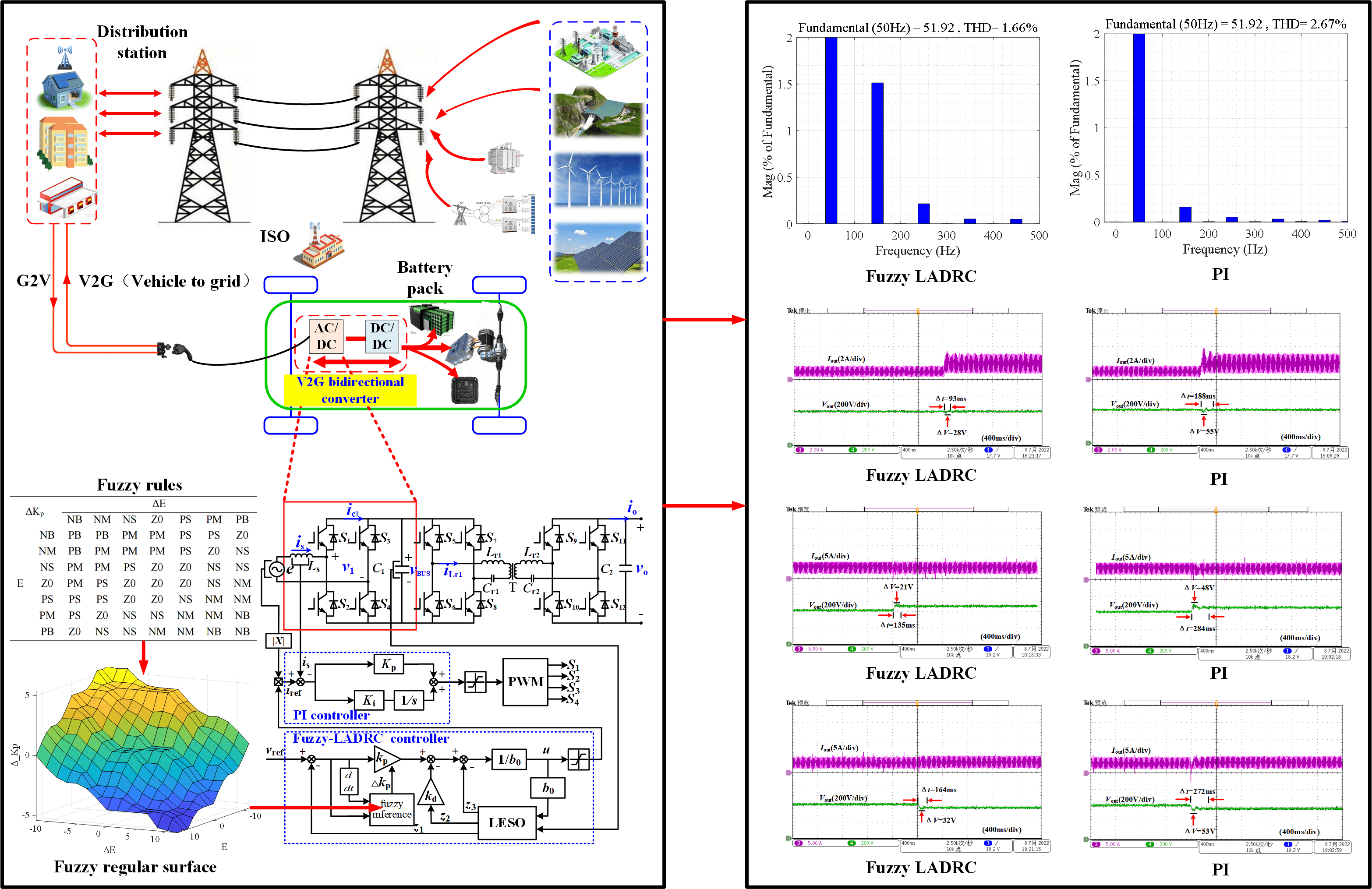
Aiming at the problems of output voltage fluctuation and current total harmonic distortion (THD) in the front stage totem-pole bridgeless PFC of two-stage V2G (Vehicle to Grid) vehicle-mounted bi-directional converter, a fuzzy linear active disturbance rejection control strategy for V2G front-stage AC-DC power conversion system is proposed. Firstly, the topological working mode of the totem-pole bridgeless PFC is analyzed, and the mathematical model is established. Combined with the system model and the linear active disturbance rejection theory, a double closed-loop controller is designed with the second-order linear active disturbance rejection control as the voltage outer loop and PI control as the current inner loop. The controller can realize self-adaptive tuning of the proportional gain coefficient of the active disturbance rejection controller through fuzzy reasoning and realize self-adaptive control. Simulation and experimental results show that this method can better solve the problems of slow system response and high total harmonic distortion rate of input current and effectively improve the system’s robustness.Graphic Abstract
Keywords
With the increasing proportion of power electronic energy in new energy power systems, the indirectness, randomness, and load time-space mismatch of renewable energy power generation seriously threaten the power grid’s security [1]. Under the background of “emission peak and carbon neutrality,” the number of electric vehicles in China has increased rapidly; the peak load of the disorderly charging of electric vehicles will further aggravate the impact on the power grid [2]. The V2G vehicle-network energy interaction technology provides a new way of absorbing a high proportion of renewable energy, assisting power grid peak regulation and frequency regulation, and ensuring the safety of the power grid [3,4]. The V2G two-stage vehicle-mounted converter replaces the single-stage V2G vehicle-mounted converter because of its high electrical isolation safety, power application efficiency, and simple control strategy. The two-stage converter comprises the front-stage AC-DC and the back-stage DC-DC power conversion circuit; AC-DC provides stable DC voltage for the system bus and realizes power factor correction.
Totem-pole bridgeless PFC converter is applied to the front stage circuit of the V2G vehicle converter because of its simple control, few switching devices, and high power density [5]. It is of great significance to output a stable bus voltage under complex working conditions and reduce the harmonic distortion rate of the circuit to improve system efficiency, reduce electromagnetic interference and loss, and improve system power density and power level. Therefore, related scholars have proposed different control strategies to improve system performance. Zhang et al. [6,7] proposed a method of inserting dead time and bipolar control. They solved the reverse recovery problem of the body diode at the moment of input voltage polarity switching by analyzing the cause of the current distortion caused by the zero-crossing point of the system. In addition, adding an auxiliary circuit and zero crossing subsection control strategy is also an effective way to reduce THD. Zhang et al. [8] proposed a method to control the auxiliary capacitor at the zero crossing point to absorb the current pulse peak. Fan et al. [9,10] proposed a method of zero-crossing pulse width modulation (PWM) control and non-zero-point PWM hybrid modulation so that the THD was minimized. The above literature has made some achievements in improving the current distortion of the inner loop and improving the power quality. However, the influence of the voltage loop on current loop control parameters is ignored; it is not conducive to the harmonic and robustness control of the circuit. The traditional double closed-loop PI has the problems of slow dynamic response and poor immunity; therefore, Zafer et al. [11] proposed a fuzzy adaptive PI control strategy to improve the transient performance of the system by dynamically adjusting the Kp and Ki parameters. To avoid the problem that the reference value of the current loop depends too much on the voltage loop, Hou et al. [12] designed a fuzzy single phase-locked loop control algorithm and input the pure sine wave into the multiplier to avoid the interference effect of the voltage noise on the system. The fuzzy control method used in [11,12] has strong robustness. However, if the system accuracy is further improved, the search range of the control rules will be expanded, and the system’s response speed will be reduced. Çelik [13] Studied the harmonic compensation and charging of the Three-phase Shunt Active Power Filter in electric vehicles and proposed an anti saturation proportional integral control method based on Lyapunov. It is proven that this method is superior to other algorithms in harmonic suppression and capacitor voltage regulation. He also studied the coordinated virtual impedance control scheme of the three-phase four-leg inverter applied to V2G, solved the problems of power sharing and voltage sag between inverter units, and realized the functions of grid connection and independent operation [14]. To avoid the influence of load and system parameters on PI, Dogan Çelik proposed an adaptive PI strategy with anti saturation DC voltage control for a three-level Vienna rectifier. This method can better track the step changes of current and voltage and has stronger robustness [15]. Ruan et al. [16,17] adopted a prediction algorithm with a faster response speed for totem pole PFC, which also considered the influence of parameter disturbance on the system, which significantly improved the anti-interference ability. For further filtering, Lv et al. [18] designed a PR controller to compensate for the harmonic components of the duty cycle predictive control, and added a notch filter structure to the voltage loop to improve the harmonic distortion of the input current. Reference [19] adopted internal model control instead of traditional PI control for a three-phase converter with strong anti-interference ability. The documents mentioned above have made excellent achievements in reducing the harmonic distortion rate of the system and improving the robustness of the system, optimizing the structure of the control system, but not considering the anti-interference ability and response speed of the system, and the structure of the algorithm is relatively complex.
Nonlinear control can effectively compensate for unknown interference. Therefore, Hasan et al.[20] designed a nonlinear fuzzy adaptive PID controller and applied it to the underwater robot, which significantly improved the anti-interference ability of the robot under the influence of deep water and surface waves. Liu et al. [21] applied auto disturbance rejection to the dynamic power control of PWR and designed two controllers with object model reference and without object model reference, respectively. The results show that the controller with the object model has better control performance. To further improve the adaptive ability of the system, Sun et al. [22] applied fuzzy auto disturbance rejection to the UAV system and compare the control effects of LADRC, PID, and Fuzzy PID. The results show that the response speed and overshoot of Fuzzy LADRC are better than other control strategies. Zhou et al. [23] applied Fuzzy LADRC to an active power filter, which effectively reduces harmonic pollution and enhances the environmental adaptability of the system. However, some studies have too many fuzzy control parameters, which increases the difficulty of practical application.
This paper proposes a Fuzzy LADRC control strategy for a totem-pole bridgeless PFC converter, which combines Fuzzy LADRC voltage loop control and PI current loop control. The method treats model errors and circuit parameter perturbations as total disturbances to the system, and the total disturbance is compensated by the Linear Extended State Observer (LESO). Fuzzy inference is added to realize the adaptive dynamic adjustment of the LADRC proportional gain coefficient, which can optimize the voltage loop’s control parameters. The optimized voltage control quantity is used as the reference quantity of the current inner loop further to reduce the total harmonic distortion of the current. The contributions and innovations of this paper also include: (1) Keep the THD within the limits of IEEE-519. (2) Model information is thoroughly used in designing the Fuzzy LADRC controller, which eliminates the defects of traditional model-free information in the design of the LADRC controller. (3) Only one fuzzy control variable is used in the design of the Fuzzy LADRC controller, which reduces the difficulty of application and the dependence on fuzzy rules; (4) Compared with the literature [6,11,16,18,24], the THD of the method proposed in this paper is lower. Finally, it is proved by simulation and experiment that the proposed method can effectively shorten the system’s response time, reduce the current harmonic distortion rate, and improve the system's robustness.
2 Working Principle and Mathematical Modeling of Totem-Pole Bridgeless PFC
2.1 Topological Structure and Modal Analysis
The circuit structure of the two-stage V2G vehicle-mounted bi-directional converter is shown in Fig. 1, composed of a filter, front-stage AC-DC converter, cascade bus capacitor, and post-stage DC-DC converter. The front AC-DC converter can convert the power grid voltage to the stable DC voltage of the system bus and carry out power factor correction (PFC). The post-stage DC-DC converter uses the system bus to adjust the voltage gain and realizes the charge and discharge management control according to the battery management system and V2G scheduling. This paper mainly studies the closed-loop control of the front-stage AC-DC converter of the V2G vehicle-mounted bi-directional converter constructed by totem-pole bridgeless PFC circuit topology.
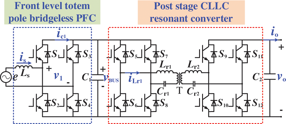
Figure 1: Circuit structure of two-stage V2G vehicle-mounted bi-directional converter
As shown in Fig. 1, the totem-pole bridgeless PFC converter is composed of an inductor Ls, high-frequency switches S1 and S2, power frequency switches S3 and S4, and capacitor C1. The converter operates in current continuous mode (CCM), which can reduce inductance current ripple and improve power factor.
High-frequency switch tubes S1 and S2 use switching frequency as the cycle to realize the storage of inductor Ls energy and load energy supply, while power frequency switch tubes S3 and S4 work at 50 Hz switching frequency to provide energy continuation channel.
According to the working state of the inductor and the working cycle of the input AC voltage, the working mode of the system in the CCM is analyzed as follows: the working mode of the energy storage of the inductor Ls when the grid voltage is positive is shown in Fig. 2a, at this time, switch tubes S1 and S3 are off, and the current passes through inductive Ls, switch tubes S2 and S4 to form a closed circuit for inductive energy storage. Load R is CLLC resonant converter powered by capacitor C1.

Figure 2: Working mode of positive half cycle circuit
Fig. 2b is a working mode diagram of the inductor Ls in the energy release stage in the positive half cycle. S4 remains on during the positive half cycle of the grid, S2 is off and S1 is on, the inductor begins to release energy, and the energy released by the inductor supplies power to R and the capacitor through the AC grid. The voltage on the load side is a dual-frequency pulsating DC voltage.
Fig. 3 shows the working mode diagram of the negative half-cycle circuit. When the inductor stores energy, switches S1 and S3 are turned on, and current flows through switches S1 and S3 to form a closed loop for the inductor to store energy. When the inductor releases energy, switch S1 is turned off, and S2 is turned on, forming a closed loop for inductor energy release.
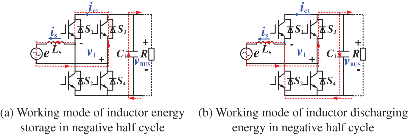
Figure 3: Working mode of negative half cycle circuit
2.2 Establishment of Mathematical Models
Take the energy storage and release state of the inductor as a switching cycle T. If the duty cycle is set as d and input voltage e is denoted as vin, then the state equation of the circuit at the inductive energy storage stage is:
The circuit state equation of the energy release phase of the inductor in the 1-d control cycle is:
Combining Eqs. (1) and (2), a steady-state relationship expression between state vector and input vector in switching control cycle T is obtained:
The small-signal disturbance is added to the input of the circuit and each state variable, and the small signal model is solved by the disturbance method. The expression of each disturbance is:
In Eq. (4), Is(t), VBUS(t), D and Vin(t) are the direct current (DC) components of each state variable,
Ignoring the high-order components and equivalently reducing the DC components at both ends in Eq. (5) according to the steady-state relationship, the equation expression of the final small-signal model can be obtained as:
From Eq. (6), the frequency domain equation of the system can be obtained as:
According to Eq. (7), the transfer function expression between the output voltage, current, and duty cycle of the system can be obtained as follows:
3 Controller Design of Totem-Pole Bridgeless PFC
The two-stage topology of the V2G vehicle-mounted converter is a complex system with strong coupling and variable parameters. In practical application, some phenomena exist, such as perturbation of battery terminal voltage parameters. Therefore, a fuzzy linear active disturbance rejection controller is designed in this paper. The controller can adaptively adjust the proportional gain of the active disturbance rejection controller through fuzzy reasoning, which realizes adaptive control. It effectively improves the robustness of the electric vehicle under complex working conditions and reduces the total harmonic distortion.
3.1 Double Closed-Loop Control Strategy
The front-stage circuit of the V2G bidirectional converter adopts double closed-loop control. The outer voltage loop stabilizes the output bus voltage, and the inner current loop realizes the function of the PFC. The structure of the double closed-loop controller is shown in Fig. 4. The flow chart of Fuzzy LADRC control is shown in Fig. 5. After sampling, the DC bus voltage vBUS output by the totem-pole bridgeless PFC converter is subtracted from the reference voltage vref, and the error value verr is obtained. The error value verr passes through the control output control quantity of the voltage outer loop Fuzzy LADRC, The control quantity is multiplied with the AC sinusoidal half-wave to obtain the current reference quantity iref consistent with the phase of the input voltage. The reference value iref is subtracted from the sampling current is of the inductor to obtain the current error value. The current error value is input to the PI compensator of the inner current ring and output control quantity. After limiting the amplitude, the microprocessor generates pulse modulation waves to realize the control of switch tubes S1~S4 and finally realize the double closed-loop control of the V2G front-stage totem-pole bridgeless PFC converter.
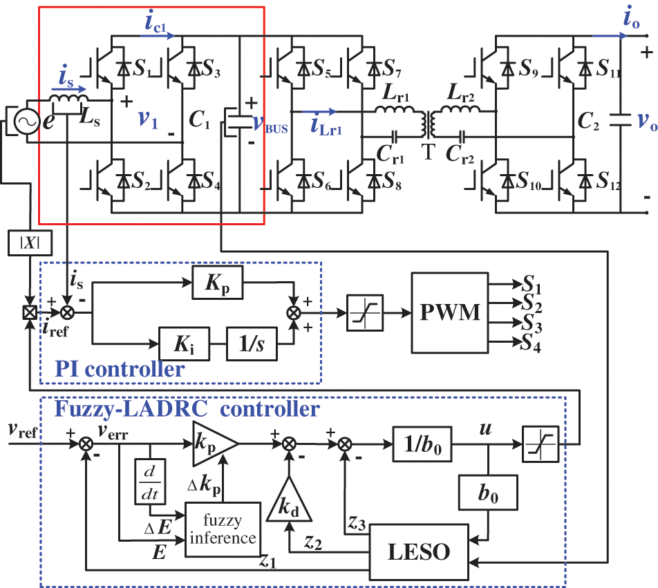
Figure 4: Fuzzy LADRC control structure

Figure 5: Flow chart of Fuzzy LADRC control
The core idea of LADRC is to use LESO to estimate the internal disturbance caused by imprecise mathematical models and parasitic parameters of devices and the external disturbance caused by environmental factors. By estimating and compensating the total disturbance of the system in real-time, the controlled object is compensated as a linear integrator in series [25]. Fig. 6 is the structure diagram of the LADRC controller used in the system.

Figure 6: Structure diagram of LADRC controller
The differential equation of the LADRC second-order controlled object is:
where, u and y are the input and output of the system respectively, w is the disturbance of the system and both a1 and a0 are unknowns, the known part of b is denoted as b0.
Set the total disturbance of the system as:
According to the totem-pole bridgeless PFC mathematical model and power balance equation, the following equation can be obtained [25]:
Let x1 =
Let
According to Eq. (13), the expression of LESO is:
where z1~ z3 are state variable matrices, then, as long as the appropriate observer gains
The expression of the proportional differential controller is:
where r is the reference signal, kp is the proportional gain of the controller, kd is the differential gain of the controller.
According to Eqs. (9)–(16), the transfer function expression of LADRC control system can be obtained as follows:
According to Eq. (17), the parameter design of the controller and observer is completed by using the pole assignment method [27], and the characteristic equation and parameters of the state observer are obtained as follows:
where wo represents the observer bandwidth, wc represents the controller bandwidth.
After the above analysis, because the totem-pole bridgeless PFC mathematical model makes some parameters of LADRC known, the parameters to be tuned for LADRC are only wo and wc. In engineering, wo = (3~5) wc is generally taken.
3.3 Fuzzy Adaptive Tuning of Gain Coefficient
Electric vehicle batteries are easily affected by ambient temperature and SOC, which leads to significant changes in their electrochemical characteristics, and the performance of the system can be improved by adaptively adjusting the controller parameters. Therefore, in this paper, the LADRC proportional gain coefficient kp is changed timely by introducing fuzzy control. The proportional gain coefficient kp can compensate for the observation error of the state observer, thereby improving the system’s robustness. The method is to calculate the difference E between the output voltage and the given voltage and the change rate of the voltage difference ΔE as the input of the fuzzy controller, the proportional gain Δkp as the output, and then according to the voltage difference E and the difference change rate ΔE adaptively adjust the proportional gain coefficient kp. The principle is: the proportional gain coefficient at the time (T−1) is kp (T−1), and the proportional gain adjustment value obtained by fuzzy reasoning is recorded as Δkp. Then, the proportional gain coefficient of LADRC at time T can be obtained as kp (T) = kp (T−1) + Δkp. The structure of the fuzzy controller is shown in Fig. 7.

Figure 7: Structure diagram of fuzzy controller
According to the experience of simulation and debugging, the range of the DC bus voltage difference E and its difference rate of change ΔE is [−12, 12]. The range of the output Δkp is [−6, 6]. The fuzzy subsets are taken as seven subsets such as NB (negative large), NM (negative medium), NS (negative small), Z0 (zero), PS (positive small), PM (positive medium), and PB (positive large).
The fuzzy rules formulated according to the experiment are shown in Table 1. Based on the fuzzy rules in Table 1, the relationship surface diagram with system error E and error change rate as input and KP as output can be obtained, as shown in Fig. 8.

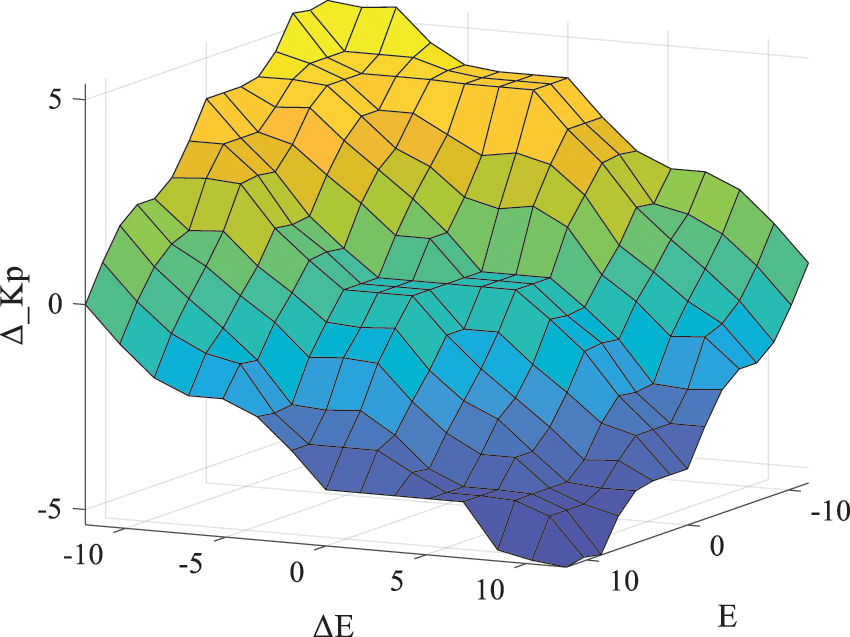
Figure 8: Δkp fuzzy rule surface graph
4 System Simulation and Experimental Analysis
The simulation models of the totem-pole bridgeless PFC power circuit, PI double closed-loop control circuit, and Fuzzy LADRC double closed-loop control circuit are built by MATLAB/Simulink. The comparative simulation experiments are carried out under different working conditions. Finally, an actual physical platform is built, and experiments are carried out to verify the correctness and effectiveness of the proposed control strategy.
4.1 System Simulation Parameters
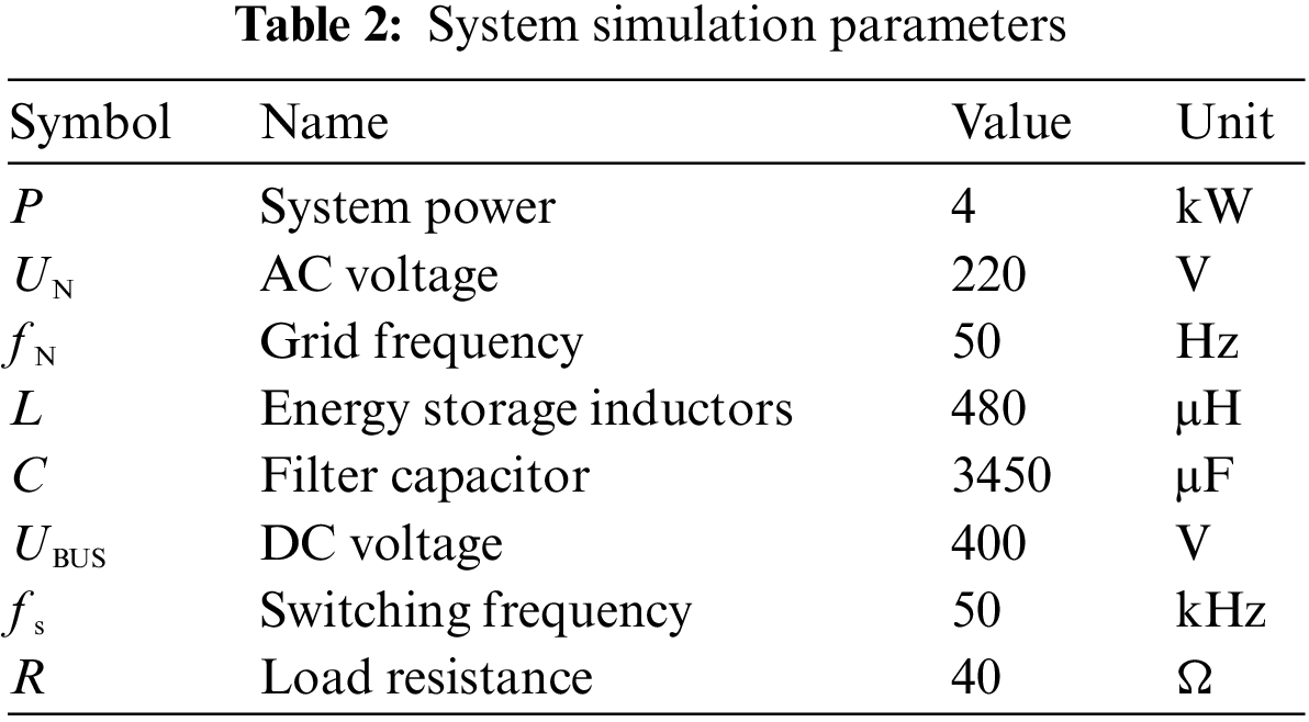
The optimal parameters of PI controller are as follows: voltage outer loop Kp = 9.95, Ki = 10000, current inner loop Kp = 3.1, Ki = 30. The LADRC voltage outer loop parameters to be adjusted include observer bandwidth wo and controller bandwidth wc. Considering their optimal values, wo is 6050 and wc is 1600. The system simulation parameters are shown in Table 2.
4.2 Matlab/Simulink Simulation
In order to verify the robustness of the proposed control strategy and the effectiveness of reducing harmonic distortion rate, Fuzzy LADRC and PI algorithms are used to compare the simulation results of the system startup, load mutation, and reference voltage mutation, respectively. Figs. 9a–9c, respectively, show the amplitude waveforms of input voltage and current at the startup time of the system and the DC voltage output waveform under the Fuzzy LADRC and PI control strategy. We can find that the input current and the input voltage are always in the same phase, and the PFC is realized; Under the Fuzzy LADRC control strategy, the system can quickly reach a stable voltage of 400 V with a small overshoot. The control steady-state recovery time is 150.1 ms, less than the recovery time under PI control of 240.4 ms. The steady-state current THD of the totem-pole bridgeless PFC controlled by Fuzzy LADRC is 2.39%, and the steady-state current THD of PI control is 3.35%. The comparison of the startup performance of the system under the two control algorithms is shown in Table 3, which verifies that the steady-state performance of the Fuzzy LADRC algorithm is better than the PI algorithm.

Figure 9: Simulation waveform of system startup under two control strategies

In order to test the response capability of the system, the reference value of the system’s output voltage is reduced from 400 to 350 V at 0.5 s, and the simulation results are shown in Fig. 10.

Figure 10: Simulation waveform of a sudden change of system output voltage under two control strategies
We can see from Fig. 10a that at the moment of a sudden change of load voltage, the change amplitude of the input current of the system under the Fuzzy LADRC control strategy is small, which effectively avoids the impact of impulse current on the system. We can see from Figs. 10b and 10c that when the output reference voltage suddenly changes, the Fuzzy LADRC controller has a faster response speed and stronger anti-interference ability. Its steady-state time is 307.7 ms, and the output voltage oscillation range is 27.2 V, while the steady-state time under PI control is greater than 400 ms and the output voltage oscillation range is 31.91 V. According to Figs. 10d and 10e, we can see that under the Fuzzy LADRC control strategy, the THD of the input current in the steady state is 1.86%, and the THD of the input current in the steady state under the PI control strategy is 2.46%. The simulation results show that Fuzzy LADRC can effectively reduce the THD and steady-state recovery time. The system performance comparison when the system output voltage suddenly changes under the two control algorithms is shown in Table 4.
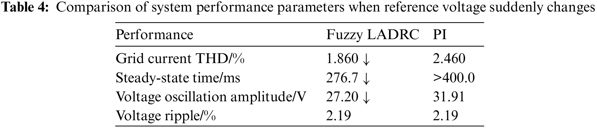
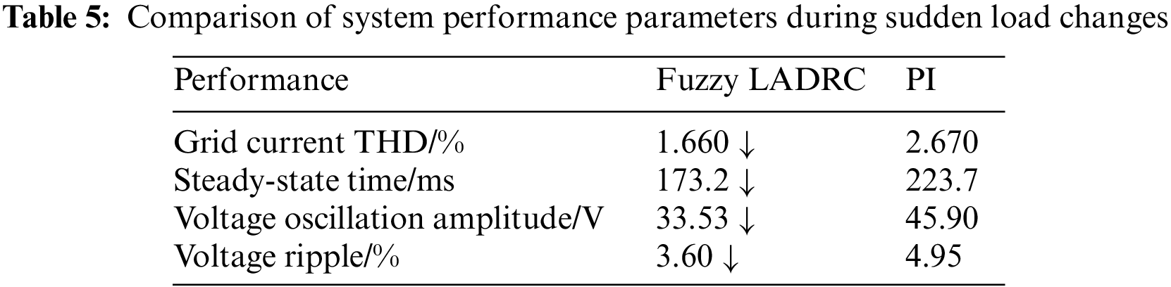
Fig. 11 shows the simulation waveform when the system's load is suddenly reduced from 40 to 20 Ω at 0.5 s. As can be seen from Fig. 11a, due to the observation and compensation effect of the Fuzzy LADRC on the load, the change of the system input current is gentler at the time of sudden load change, so the power fluctuation of the system is small. Figs. 11b and 11c show the output voltage waveform of the system when the load changes suddenly under the two control algorithms. It can be seen that the output voltage under the two control methods has an inevitable fluctuation; under the Fuzzy LADRC control strategy, the system reaches a steady state after 162.9 ms, and the output voltage oscillation range is 33.53 V. However, under PI control, the system needs 223.7 ms to reach a stable voltage output state, and the oscillation range of the output voltage is large, which is 45.9 V. Figs. 11d and 11e show the input current THD under Fuzzy LADRC control and PI control, respectively; we can see that the THD under Fuzzy LADRC control is only 1.66%, which is less than the value of PI control (2.67%). The system performance comparison of the two control algorithms in case of sudden load change is shown in Table 5.

Figure 11: Load sudden change simulation waveform
According to the simulation results of the system under different working conditions, we can find that the Fuzzy LADRC control strategy can effectively improve the dynamic and steady-state performance of the totem-pole bridgeless PFC topology circuit and effectively reduce THD. Simulation results verify the effectiveness of this method.
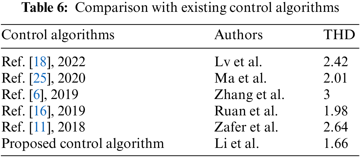
Table 6 compares the inhibition ability of THD under recent research results. We can find that the method in this paper has a strong THD suppression ability, which plays a vital role in improving the performance of the V2G bidirectional converter.
We have developed a 3 kW V2G bidirectional converter to verify the control effect of the proposed method in practical application. The experimental platform and prototype are shown in Figs. 12 and 13, respectively, and the prototype parameters are shown in Table 7.
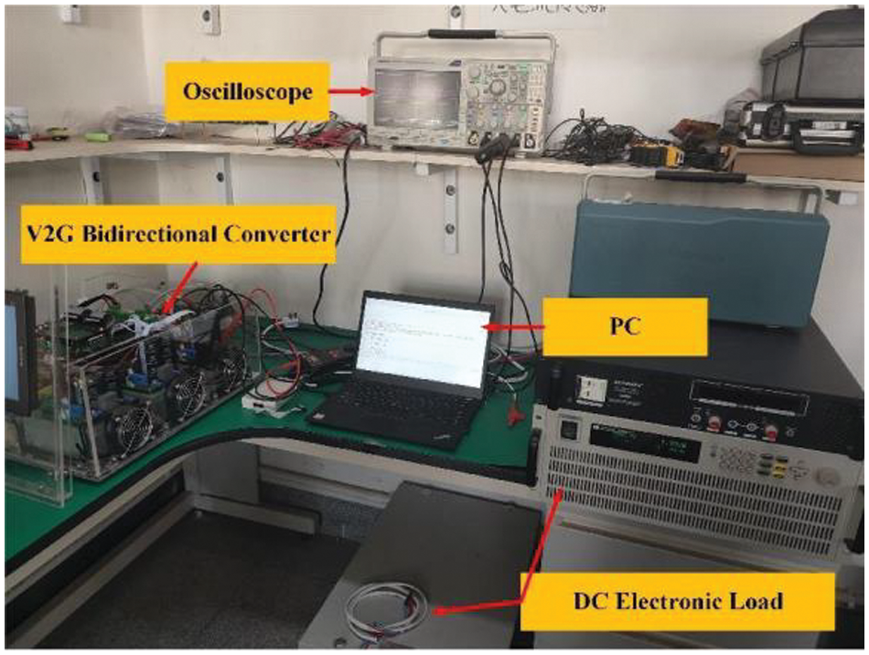
Figure 12: Experimental platform
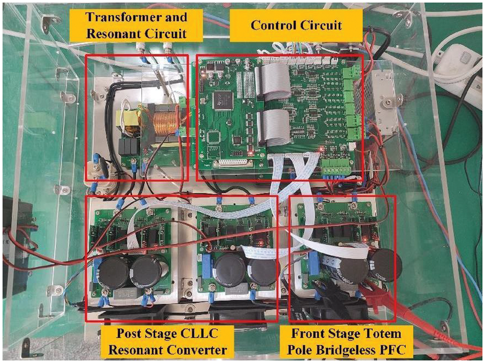
Figure 13: V2G experimental prototype
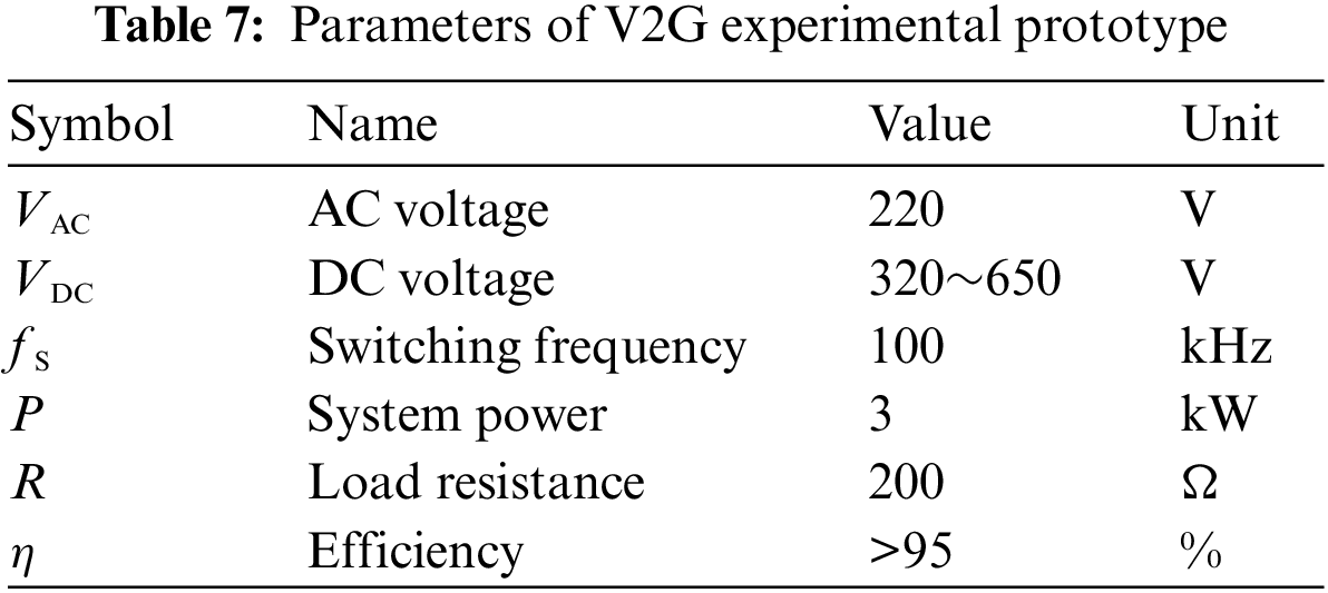
Fig. 14 is the waveform of the system input voltage and inductance current; we can find that the voltage and current remain in phase. Power factor correction is realized.

Figure 14: Waveform of system input voltage and inductive current
When the output DC voltage is 400 V, and the load changes from 200 to 100 Ω, the comparison of voltage and current under the two control methods is shown in Fig. 15. We can find that the voltage fluctuation range of the PI controller is 55 V, and the steady state is restored within 188 ms, while the voltage fluctuation range of the Fuzzy LADRC controller is only 28 V. The steady state is restored after 93 ms.

Figure 15: Experimental results of a sudden increase in load
When the output voltage is 400 V and the load changes from 200 to 400 Ω, the experimental waveform is shown in Fig. 16. We can find that the voltage fluctuation amplitude of the Fuzzy LADRC control is 17 V, which is restored to the reference voltage after 91 ms, the voltage fluctuation amplitude of the PI control is 45 V, and the steady-state recovery time needs 152 ms. We can find that the Fuzzy LADRC has a faster adjustment time, can compensate for load disturbance, and has better robustness.

Figure 16: Experimental results of sudden load reduction
When the load is 100 Ω, the experimental waveform of the output voltage from 400 to 450 V is shown in Fig. 17. The experimental waveform of the output voltage from 400 to 350 V is shown in Fig. 18.
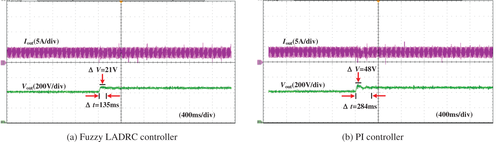
Figure 17: Experimental results of output voltage changing from 400 to 450 V
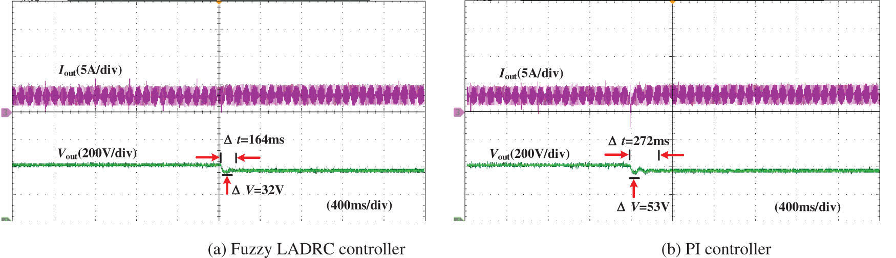
Figure 18: Experimental results of output voltage changing from 400 to 350 V
According to Figs. 17 and 18, We can see that the Fuzzy LADRC has faster regulation speed when the output voltage changes, which are 135 and 164 ms, respectively. Moreover, the voltage fluctuation is lower, 21 and 32 V, respectively. In contrast, the PI regulation time is relatively slow, and the voltage fluctuation is large; the regulation time is 284 and 272 ms, respectively. Moreover, the voltage fluctuation is 48 and 53 V, respectively.
The experimental results show that the control method in this paper has more robust adaptability, can compensate for the unknown disturbance in real-time, and the output voltage is smoother when the working condition changes.
This paper proposed a Fuzzy LADRC control strategy for the V2G totem-pole bridgeless PFC converter. Through the simulation and experimental comparison with the traditional PI control, the conclusions are as follows: (1) The disturbance caused by load change can be solved by self-tuning the LADRC proportional gain coefficient through fuzzy reasoning. The experimental results show that compared with PI control, the response time of this method at the sudden increase and decrease of the output voltage is reduced by 95 and 61 ms, respectively, and the voltage fluctuation is reduced by 27 and 28 V, respectively. When the load suddenly increases and decreases, the response time decreases by 149 and 108 ms, respectively, and the voltage fluctuation decreases by 27 and 21 V, respectively. Therefore, the response speed of this method is faster, the anti-interference ability is significantly improved, and the dynamic and steady-state performance of the system is improved considerably. (2) Fuzzy LADRC controllers can estimate and compensate for load disturbance in real time. Therefore, compared with the PI controller and references [6,11,16,18,24], the control strategy in this paper can effectively reduce the total harmonic distortion rate of input current when the load changes and the optimal value is 1.66%. (3) The limitation of the method proposed in this paper is that the fuzzy controller needs a higher experience. Therefore, the future work direction is to improve the fuzzy controller and start to study the energy coordination control of the V2G converter.
Funding Statement: This project is supported by the Science and Technology Project of State Grid Corporation of China (W22KJ2722005). Tianyou Innovation Team of Lanzhou Jiaotong University (TY202009).
Conflicts of Interest: The authors declare that they have no conflicts of interest to report regarding the present study.
References
1. Liu, Z. C., Peng, D. G., Zhao, H. R., Wang, D. H., Liu, Y. C. (2022). Development prospects of energy storage participating in auxiliary services of power systems under the targets of the dual-carbon goal. Energy Storage Science and Technology, 11(2), 704–716. [Google Scholar]
2. Sun, W. Q., Luo, J., Zhang, J. (2021). Energy storage capacity allocation and influence factor analysis of a power system with a high proportion of wind power. Power System Protection and Control, 49(15), 9–18. [Google Scholar]
3. National Energy Administration (2022). Administration. Scientific and technological innovation plan in the energy field during the 14th Five Year Plan Period. http://www.nea.gov.cn. [Google Scholar]
4. Liu, Z. F., Liu, Y. Y., Wang, X. Y., Qu, G. Q. (2022). Operation schedule optimization of energy storage and electric vehicles in a distribution network with renewable energy sources. Proceedings of the CSEE, 42(5), 1813–1826. [Google Scholar]
5. Sun, Z., Wang, Y. J. (2022). Soft switch control transformation based on totem pole bridgeless PFC. Electric Power Engineering Technology, 41(1), 70–76. [Google Scholar]
6. Zhang, X., Lin, Z. X., Yao, J. M., Guo, T. L. (2019). Totem-pole bridgeless PFC converter in DCM with synchronous rectification. Microelectronics, 49(4), 502–507. [Google Scholar]
7. Leonardo, S. M., Alexsandra, R., Samir, A. M., Tells, B. L. (2019). Research on the zero-crossing problem of totem pole PFC current based on GaN. 2019 IEEE 15th Brazilian Power Electronics Conference and 5th IEEE Southern Power Electronics Conference (COBEP/SPEC), pp. 1–6. Brazil. [Google Scholar]
8. Zhang, B. H., Lin, Q., Shimada, Y. S., Imaoka, J., Shoyama, M. et al. (2016). Analysis and reduction method of conducted noise in GaN HEMTs based totem-pole bridgeless PFC converter. 2016 IEEE 8th International Power Electronics and Motion Control Conference (IPEMC-ECCE), pp. 274–278. Asia. [Google Scholar]
9. Fan, W. T., Yeung, S. C., Chung, S. H. (2019). Optimized hybrid PWM scheme for mitigating zero-crossing distortion in totem-pole bridgeless PFC. IEEE Transactions on Power Electronics, 34(1), 928–942. DOI 10.1109/TPEL.2018.2819422. [Google Scholar] [CrossRef]
10. Yeung, S. C., Fan, W. T., Chung, S. H. (2017). A totem-pole PFC using hybrid pulse width modulation scheme. 2017 IEEE 3rd International Future Energy Electronics Conference and ECCE Asia (IFEEC 2017-ECCE), pp. 2048–2053. Asia. [Google Scholar]
11. Zafer, O., Ahmet, K. (2018). The performance analysis of AC-DC bridgeless converter using fuzzy self-tuning and comparing with PI control method. Journal of Intelligent & Fuzzy Systems, 35(4), 4629–4642. DOI 10.3233/JIFS-172134. [Google Scholar] [CrossRef]
12. Hou, S., Sun, W. X., Zhang, X. H. (2021). Research on improved bridgeless boost PFC topology based on fuzzy control. Power Electronics, 55(7), 46–49. [Google Scholar]
13. Çelik, D. (2022). Lyapunov based harmonic compensation and charging with three phase shunt active power filter in electrical vehicle applications. International Journal of Electrical Power and Energy Systems, 136(12), 107564. DOI 10.1016/j.ijepes.2021.107564. [Google Scholar] [CrossRef]
14. Celik, D., Meral, M. E. (2022). A coordinated virtual impedance control scheme for three phase four leg inverters of electric vehicle to grid (V2G). Energy, 246, 123354. DOI 10.1016/j.energy.2022.123354. [Google Scholar] [CrossRef]
15. Celik, D. (2022). Performance analysis of three level three switch vienna-type rectifier based on direct power control. Balkan Journal of Electrical and Computer Engineering, 10(2), 170–177. [Google Scholar]
16. Ruan, Z. H., Song, W. X., Lin, H. M. (2019). An model predictive control with duty cycle control for PWM rectifier. 2019 IEEE International Symposium on Predictive Control of Electrical Drives and Power Electronics (PRECEDE), pp. 1–5. China. [Google Scholar]
17. Wang, P., Ben, H. Q., Wang, X. S. (2017). Research on predictive control algorithms for single-phase single-stage PFC converter. Power Electronics, 55(1), 62–64. [Google Scholar]
18. Lv, Z. Y., Yu, X. H., Wu, M., Chen, J. X. (2022). Research on predictive control of interleaved PFC converters. Information Technology, 29(2), 62–64. DOI 10.13274/j.cnki.hdjz.2022.02.014. [Google Scholar] [CrossRef]
19. Song, W. X., Yin, Y. (2012). A control strategy of three-phase PWM rectifier based on internal model control. Transactions of China Electrotechnical Socienty, 27(12), 94–101. [Google Scholar]
20. Hasan, M. W., Abbas, N. H. (2022). Disturbance rejection for underwater robotic vehicle based on adaptive fuzzy with nonlinear PID controller. ISA Transactions, 130, 360–376. DOI 10.1016/j.isatra.2022.03.020. [Google Scholar] [CrossRef]
21. Liu, Y. Y., Liu, J. Z., Zhou, S. L. (2018). Linear active disturbance rejection control for pressurized water reactor power. Annals of Nuclear Energy, 111(7), 22–30. DOI 10.1016/j.anucene.2017.08.047. [Google Scholar] [CrossRef]
22. Sun, C. H., Liu, M. Q., Liu, C. A., Feng, X. L., Wu, H. (2021). An industrial quadrotor UAV control method based on fuzzy adaptive linear active disturbance rejection control. Electroncis, 10(4), 376. DOI 10.3390/electronics10040376. [Google Scholar] [CrossRef]
23. Zhou, X. S., Cui, Y. Y., Ma, Y. J. (2021). Fuzzy linear active disturbance rejection control of injection hybrid active power filter for medium and high voltage distribution network. IEEE Access, 9, 8421–8432. DOI 10.1109/ACCESS.2021.3049832. [Google Scholar] [CrossRef]
24. He, H., Si, T., Sun, L., Liu, B., Li, Z. (2020). Linear active disturbance rejection control for three-phase voltage source PWM rectifier. IEEE Access, 8, 45050–45060. DOI 10.1109/ACCESS.2020.2978579. [Google Scholar] [CrossRef]
25. Ma, Y. J., Tao, L., Zhou, X. S., Hong, F. P., Shi, X. Q. et al. (2020). Fuzzy adaptive control of voltage loop in wind power system combined with linear active disturbance rejection control. Acta Energiae Solaris Sinica, 41(12), 330–337. [Google Scholar]
26. Wang, Y., Cheng, Z. J., Chen, X. Z., Yang, H. D., Shi, K. H. (2022). Design of wireless power transmission device based on linear active disturbance rejection control. High Voltage Engineering, 48(6), 2401–2409. [Google Scholar]
27. Cao, Y. F. (2018). Application of active disturbance rejection control in inverter system (Master’s Thesis). Nanjing University of Aeronautics and Astronautics, Nanjing, China. [Google Scholar]
Cite This Article
 Copyright © 2023 The Author(s). Published by Tech Science Press.
This work is licensed under a Creative Commons Attribution 4.0 International License , which permits unrestricted use, distribution, and reproduction in any medium, provided the original work is properly cited.
 Downloads
 Citation Tools