
 Submit a Paper
 Propose a Special lssue
 Open Access
ARTICLE

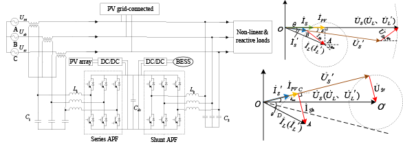
The Full Load Voltage Compensation Strategy in Capacity Configuration of UPQC Integrated PV-BESS
1 Jiangsu Key Laboratory of Power Transmission & Distribution Equipment Technology, Jiangsu University of Technology, Changzhou, 213001, China
2 School of Electrical and Information Engineering, Jiangsu University of Technology, Changzhou, 213001, China
* Corresponding Author: Kai Li. Email:
Energy Engineering 2023, 120(5), 1203-1221. https://doi.org/10.32604/ee.2023.025796
Received 31 July 2022; Accepted 09 October 2022; Issue published 20 February 2023
 View Full Text
 Download PDF
Abstract
Unified power quality conditioner (UPQC) with energy storage is commonly based on conventional capacity configuration strategy with power angle control. It has problems such as phase jumping before and after compensation. DC-link cannot continuously emit active power externally. Therefore, this paper presents the compensation strategy of full load voltage magnitude and phase in capacity configuration of UPQC. The topology of UPQC is integrated a series active power filter (SAPF), a shunt active power filter (PAPF) and a photovoltaic-battery energy storage system (PV-BESS). The principle of full load voltage compensation is analyzed based on the PV-BESS-UPQC topology. The magnitude constant of load voltage is maintained by controlling the appropriate shunt compensation current. Then the UPQC capacity configuration is carried out using the full load voltage compensation strategy. The compensation capacity of UPQC series and shunt units are reduced. Finally, the simulation results show that the proposed compensation strategy reduces the capacity configuration by 5.11 kVA (36.4%) compared to the conventional compensation strategy. The proposed strategy can achieve full compensation of the load voltage, which can effectively reduce the capacity allocation and improve the economy of UPQC. It also has the PV-BESS units' ability of providing active power and can stabilize the DC-link voltage.Graphic Abstract
Keywords
With the continuous development of the electric power industry, the power quality issue is getting more and more attention. Compared with the traditional electrical loads, the new generation of power distribution system consisting of power electronic devices also requires higher and higher power quality. Power quality becomes a problem that cannot be ignored [1,2]. Therefore, various power quality conditioners have emerged, such as active power filter (APF), static reactive power compensator (SVC) and dynamic voltage restorer (DVR). However, these conditioners can only solve part of the power quality problems. While the unified power quality conditioner (UPQC) can solve most of the power quality problems, so it has been discussed and studied by scholars [3].
At present, conventional UPQC has the problem of insufficient DC-link energy storage, which limits the use and development of UPQC. Some scholars have proposed adding distributed generation units on the DC-link for solving the problems such as low compensation efficiency of UPQC [4,5]. In [6,7], authors proposed a PV integrated with UPQC to produce clean energy and improve the power quality problems. However, long interruption and deep voltage sag were not considered in their study. In such case, energy storage system like BESS can be interfaced with the PV-UPQC. It can be a great support for continuously providing real power to the load. When UPQC operating in standalone mode, BESS is most essential for renewable energy systems. The extra cost of the BESS is justified when the system is applied for critical loads such as semiconductor industries, hospitals, etc. An uninterrupted supply of best quality power is of supreme importance. Therefore, The UPQC is supported by the PV and BESS was design in this work. The PV is attached to the DC-link through DC-DC boost converter and the BESS [8,9]. Generally, the PV system supplies the active power to the load. But when the PV is unable to supply the power. Then, the BESS activates and provides power especially during the longer-term voltage interruption in order to enhance the stability of the distribution power system. In [10–12], researchers tried to design the DC-link voltage regulation algorithm to ensure stable and constant DC-link capacitor voltage. The UPQC controller become more complex and computational burden. However, PV-BESS can be considered a better alternative since it can support DC-link capacitor of a UPQC externally. It can reduce the burden on the DC-link capacitor.
For the UPQC-related compensation strategy with energy storage units on the DC-link, Devassy et al. [13–15] proposed a UPQC power compensation strategy based on power angle control. The series units emit a certain size of reactive power to share the capacity burden of the shunt units. But the power angle is not necessarily equal to the phase jump angle of the grid voltage. It may cause a phase jump before and after the load voltage compensation. In [16], a UPQC voltage compensation strategy based on reactive power control is proposed. It eliminates the active circulating current. But it presupposes that the compensation voltage on the series-connected unit should follow the principle of mutual perpendicularity with the supply current. That makes the phase of the compensated load voltage uncontrolled. It causes the phase jump of the load voltage before and after compensation. In [17], authors proposed a compensation strategy based on coordinated active and reactive power distribution. It maintains a constant compensation capacity of the shunt unit to distribute the active power provided by the power supply and the energy storage unit. But the voltage and current amplitudes on the series unit after compensation are large. That results in maintaining a high compensation capacity of the series unit. In [18], a UPQC power coordination compensation strategy where the load reactive power is mainly provided by the shunt unit is studied. When the load reactive power demand is greater than the rated capacity set by the shunt unit. The excess is provided by the series unit. But the capacity burden on the series unit is increased when the excess is larger.
It is thus clear that how to achieve full compensation of load voltage magnitude and phase. While reducing the capacity configuration and cost of UPQC is an urgent problem in current UPQC applications. Therefore, this paper takes the PV-BESS-UPQC as a topology of study. It analyzes the problems of conventional PV-BESS-UPQC power angle control. Then the compensation strategy of full load voltage magnitude and phase in capacity configuration has been proposed. Also, the capacity configuration principles and methods of series and parallel units are analyzed. Finally, the correctness and effectiveness of the proposed strategy are verified by simulation and experiment.
2 Conventional Power Angle Compensation Strategy in PV-BESS-UPQC
The structure of UPQC mainly consists of a series active power filter (SAPF) and a shunt active power filter (PAPF). The PV-BESS integrated UPQC is added with Boost converter and photovoltaic array. The construction of PV-BESS-UPQC is displayed in Fig. 1.
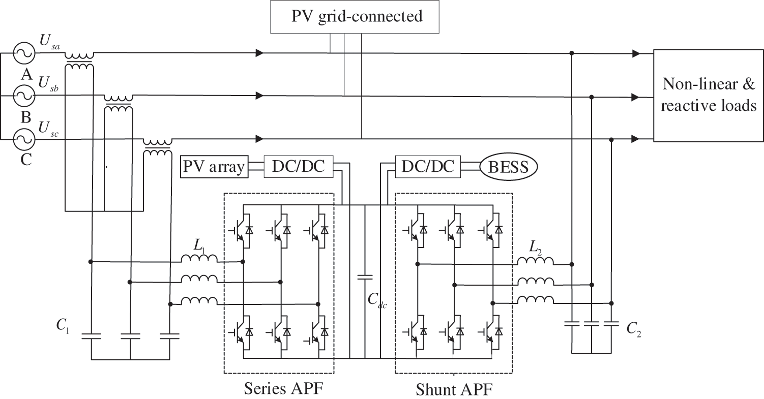
Figure 1: System configuration of PV-BESS-UPQC
When the UPQC with PV-BESS is in operation, the series compensation unit is equated to a controlled voltage source. The series compensation unit is mainly used to compensate for the sudden change of grid voltage, unbalance and harmonics to ensure the voltage quality on the load. The PV array and BESS are connected to the DC-link through the DC/DC converter. It can suppress the fluctuation of the DC-link voltage, buffer the voltage and power to ensure the stability of the DC-link voltage. PV-BESS also provide active power to the load when necessary. Since the PV array is connected to the UPQC DC-link directly, the PV array is constructed in a way such that the maximum power point (MPP) voltage is equivalent to the reference DC-link voltage. During nominal conditions, the rating of PV array ensures that the load active power is delivered by the PV array and power is supplied to the grid and charging BESS by the PV array as well. Besides, the BESS is designed in a way that, when the PV array generate less power than the DC-link load demand, the BESS provides the insufficient power equivalent to the decrease in DC-link voltage. Moreover, when there is no power produced by PV array, the BESS will supply the total load demand.
In conventional PV integrated UPQC compensation control, the series converter unit only operates when voltage drops occur and only provides active power and does not participate in the compensation of load reactive power. In [18], a UPQC-PV power compensation strategy based on power angle control is proposed. It makes the series converter unit emit a certain size of reactive power to share the burden of the shunt converter.
The phase diagram of UPQC-PV operation based on power angle control under voltage drops is displayed in Fig. 2. The core of UPQC power angle control is how to select the power angle
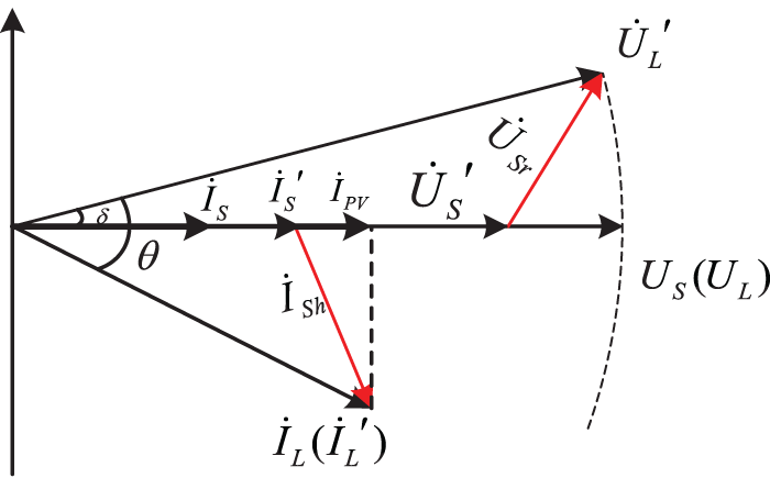
Figure 2: UPQC-PV phase diagram based on power angle control
3 Strategy of Full Load Voltage Compensation in PV-BESS-UPQC
The magnitude and phase of voltage jump is the most common and the most concerned power quality problem for power users. In response to the problem of load voltage phase which is often not considered in the conventional energy storage UPQC power angle compensation strategy. This paper proposes a full load voltage compensation strategy of magnitude and phase. Its compensation phase diagram is shown in Fig. 3.
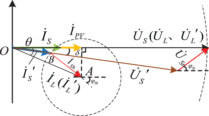
Figure 3: Phasor diagrams for full compensation of load voltage
As shown in Fig. 3, the supply voltage has a drop in amplitude and a jump fault in phase. At this time, if it is not compensated, the load voltage will change with it. The load equipment cannot work normally and cause economic loss to the user. The full load voltage compensation strategy means: firstly, the series unit compensation voltage
In summary, the full compensation of the load voltage considers the following four factors: The post-fault supply voltage
In Eq. (1),
4 Capacity Configuration of PV-BESS-UPQC Based on Full Load Voltage Compensation Strategy
4.1 Selection of Compensation Current for UPQC Shunt Units
In the full load voltage compensation strategy, the magnitude of the supply current
Specifically, the appropriate shunt compensation current
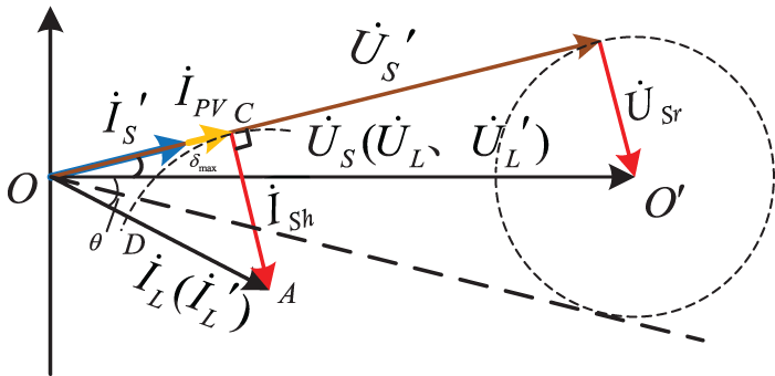
Figure 4: Phase diagram of
As shown in Fig. 4 above, the phase diagram of
In Fig. 4, the center of the circle is chosen with
In summary,
4.2 Capacity Configuration of Series Unit of UPQC
For the convenience of analysis, the supply voltage drop factor
According to the compensation triangle composed of phase quantities
According to the compensation triangle formed by the phase quantities
The phase angle
The compensation capacity of the series unit is expressed as:
Normally to meet the requirements of high power factor, power factor is generally required to be 0.85 to 0.9. The variation range of
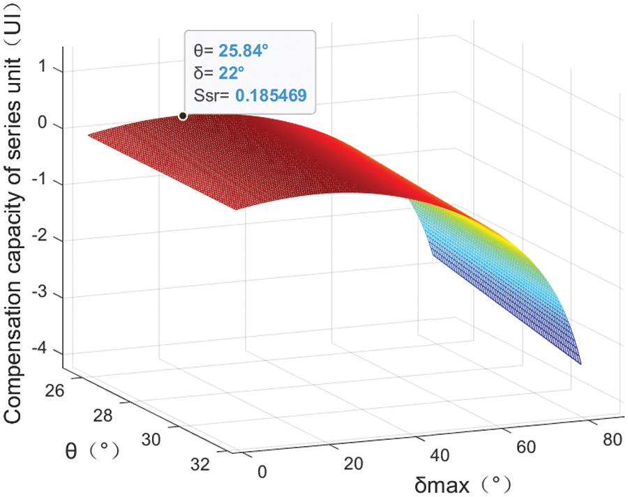
Figure 5: Three-dimensional relationship between compensation capacity of series unit
In this conventional compensation strategy, it is stipulated that the amplitude of
From Eqs. (9) and (10), it can be seen that the installed capacity required for the series-connected units of the compensation strategy proposed can be reduced
4.3 Capacity Configuration of Shunt Unit of UPQC
In Fig. 3,
From the selection method of
According to the compensation triangle formed by the phase quantities
From the Eq. (13),
Further from the trigonometric relationship, the phase angle of
From the above analysis, it can be seen that the compensation capacity of the shunt unit under the compensation strategy proposed in this paper is shown as follows:
The relationship between the shunt unit compensation capacity
In the conventional power angle compensation strategy shown in Fig. 2, the shunt compensation capacity in the event of a supply voltage drop is obtained as:
And the power factor is generally required to be 0.85 to 0.9. The variation range of
From Eqs. (17) and (19), it can be seen that conventional power angle strategy requires the same installed capacity as the shunt units of the compensation strategy proposed in this paper.
4.4 Capacity Configuration of PV-BESS Unit of UPQC
Configuration of PV-BESS unit capacity includes the capacity configuration of PV arrays and the energy storage system. The capacity configuration in PV power generation output is mainly affected by solar radiation illumination, ambient temperature and other factors. The capacity of PV arrays is designed as follows:
where:
The capacity of the energy storage system is mainly determined by the following parameters: the size of the active power of the load, the degree of drop of the supply voltage and the duration of the drop. The capacity is determined by the worst possible working conditions of the user load. The worst working condition of the load considers the situation of power interruption. When the energy storage unit realizes the uninterrupted power supply to the load, that is, the load active power is completely provided by the energy storage unit. The capacity of the energy storage unit is designed as follows:
where:
In summary, the compensation strategy proposed in this paper achieves complete compensation of the load voltage. Compared with the conventional compensation strategy, the compensation capacity of UPQC can be greatly reduced. The capacity cost of UPQC series and shunt units can be saved. Also, the capacity design of PV-BESS unit ensures the uninterrupted power supply to the load.
5 Control Strategy of PV-BESS-UPQC
5.1 Control Strategy of Series-Shunt Unit in UPQC
The Figs. 6 and 7 show the diagram of series and shunt units control strategy of UPQC. In these figures,
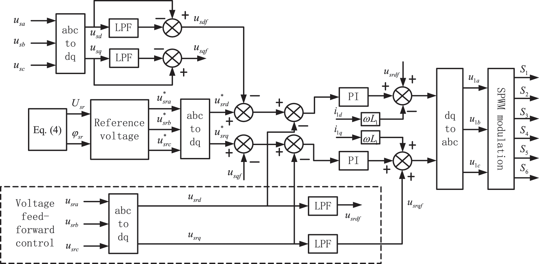
Figure 6: Control strategy of UPQC series unit
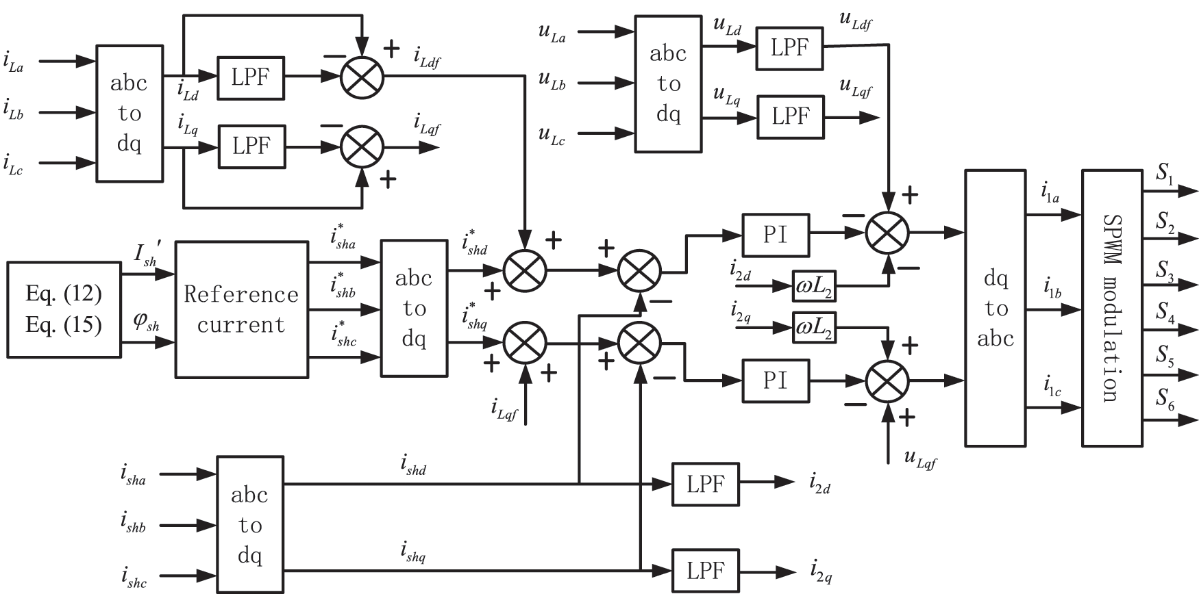
Figure 7: Control strategy of UPQC series unit
To achieve compensation of possible harmonic components in the supply voltage, the required voltage harmonic compensation value is extracted by a low-pass filter. This harmonic compensation value is used as part of the
The control block diagram of the shunt converter unit is shown in Fig. 7. Based on the full compensation strategy,
5.2 Control Strategy of PV-BESS Unit in UPQC
The PV-BESS configuration displayed in Fig. 8 comprises the PV array, BESS, Boost converter, Buck/Boost converters. The BESS is attached parallelly to the DC-link capacitor utilizing buck-boost converter, so the stability of the UPQC is improved for compensating power quality problem. The BESS unit is charged and discharged through a bidirectional Buck/Boost converter connected to the DC-link of the UPQC. It is in Buck circuit mode when T2 is disconnected and T3 is on, the power supply charges the energy storage unit. It is in Boost circuit mode when T3 is disconnected and T2 is on, the PV-BESS unit releases excess energy to meet the requirements of the system load. Under normal operating conditions, the output current
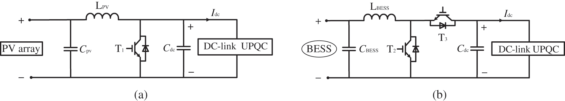
Figure 8: PV array and bidirectional Boost converter structural diagram (a), BESS and bidirectional Buck/Boost converter structural diagram (b)
When the grid voltage drop is deep, the PV-BESS unit can play a limiting role on the grid current. It can reduce the risk of insufficient compensation capacity of UPQC in the case of deep grid voltage drop. In order to meet the fast energy leveling and improve the DC-link voltage constancy, the DC-link adopts the double closed-loop control strategy of voltage external loop control and current internal loop control. It enhances the ability of bus voltage self-regulation.
The PV system output power,
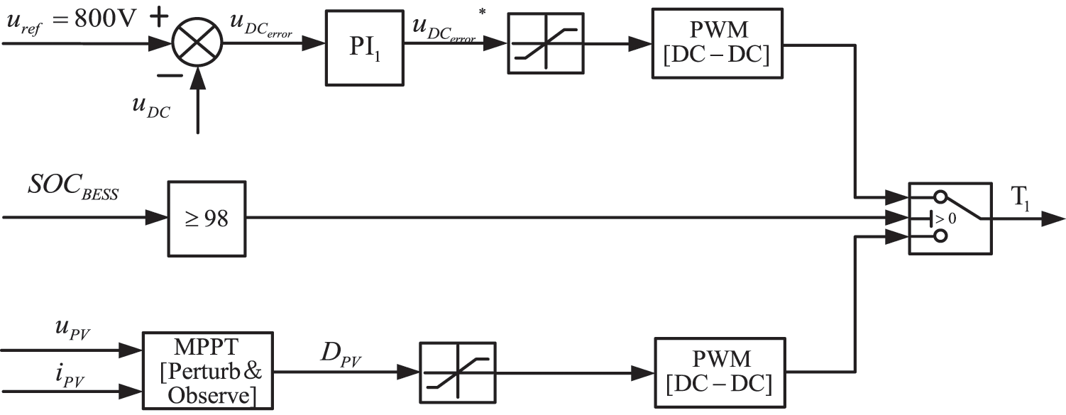
Figure 9: BESS DC-DC buck-boost converter controller scheme
In Fig. 10, it shows the bidirectional converter Buck-Boost DC-DC controller for charging and discharging mode that contains embedded internal control loops and external control loops. The difference between the DC voltage reference value
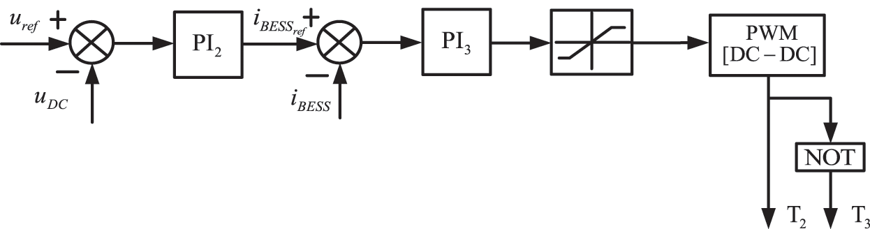
Figure 10: BESS DC-DC buck-boost converter controller scheme
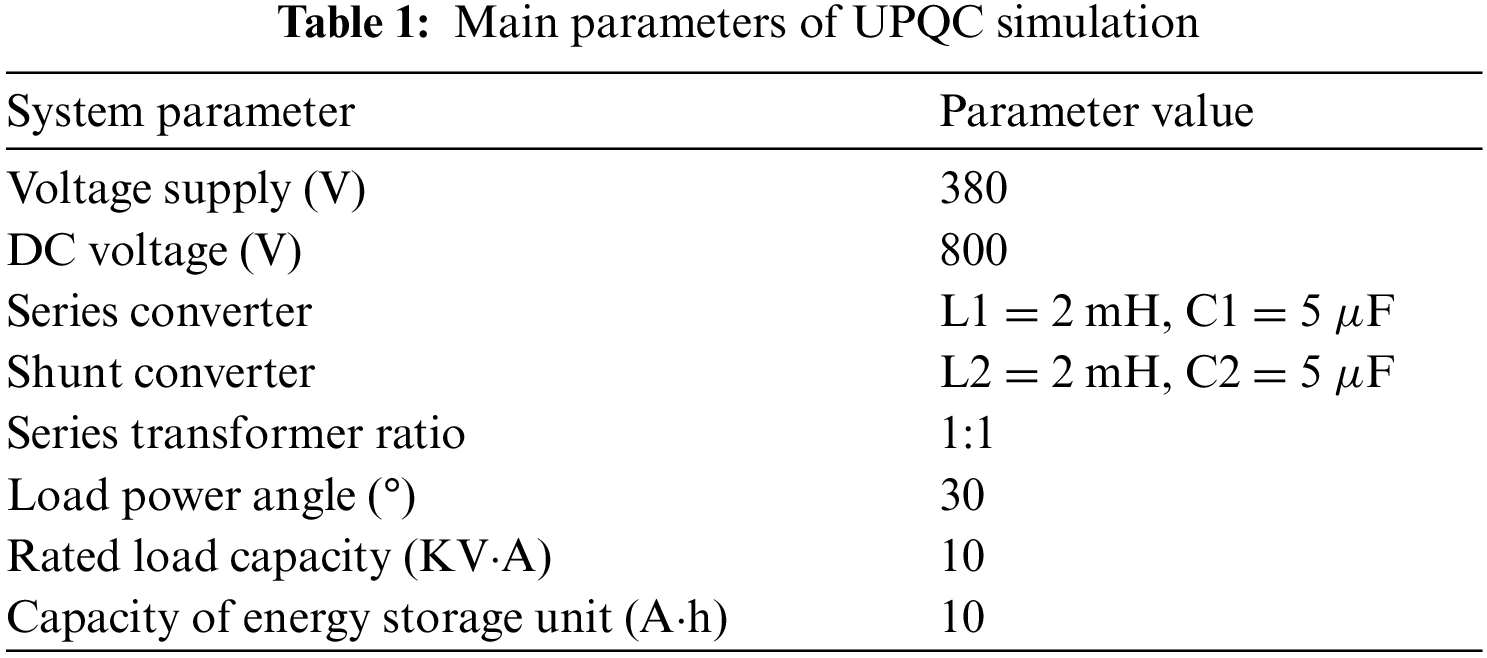
In order to verify the correctness and effectiveness of the proposed full load voltage compensation strategy in capacity configuration of UPQC integrated PV-BESS. The series and shunt unit compensation capacities are simulated using the MATLAB/Simulink simulation platform. The conventional compensation strategy and the full load voltage compensation strategy proposed in this paper are compared, respectively. The UPQC-PV related simulation parameters are set in Table 1.
The simulation is set at 2 s when the phase of the power supply voltage has a transient 20% drop of amplitude (60 V) and a
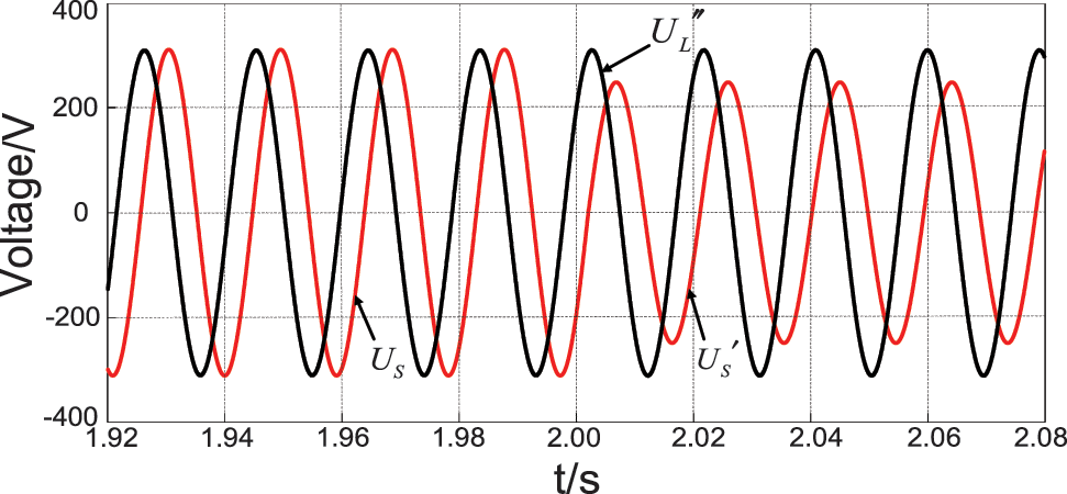
Figure 11: Conventional power angle compensation strategy supply voltage, load voltage waveform
The comparison of the supply voltage and load voltage waveforms before and after using the conventional power angle compensation strategy is shown in Fig. 11. Before 2 s in the simulation, when the supply voltage works normally, the load voltage
When using the full load voltage compensation strategy proposed in this paper. The comparison of supply voltage and load voltage waveforms before and after compensation is shown in Fig. 12a. Before 2 s in the simulation, the amplitude and phase of load voltage
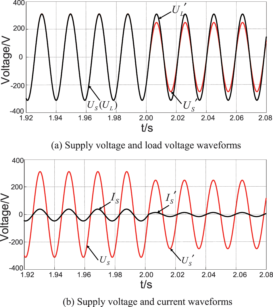
Figure 12: The proposed full load voltage compensation strategy supply voltage and load voltage waveforms (a), supply voltage and current waveforms (b)
The waveforms of supply voltage and load voltage before and after compensation are shown in Fig. 12b. When the supply voltage works normally, before 2 s in the simulation, the supply current
When using the conventional power angle compensation strategy. The active and reactive power simulation waveforms of each unit of the system are shown in Fig. 13. When the supply voltage is working normally, the power provides all the active power 8.66 kW to the load. The reactive power provided by series unit is 7.50 kVar. The reactive power provided by shunt unit is 1.16 kVar. The series and shunt units provide all the reactive power 8.66 kVar to the load. After 1 s, when the power supply voltage drops, the active power provided by the power supply decreases to 6.93 kW. As shown in Figs. 13a and 13d, the difference of active power 1.73 kW is provided by the energy storage unit to the load through the shunt unit. Meanwhile, the active power absorbed by the series unit decreases to 3.34 kW. The reactive power provided by series unit increases to 7.99 kVar. The compensation capacity of 8.66 kVA after voltage drops is kept unchanged, as shown in Fig. 13b. The active power provided by the shunt unit increases to 5.34 kW. The reactive power provided by the shunt unit decreases to 0.65 kVar. The compensation capacity after voltage drops increases to 5.38 kVA, as shown in Fig. 13c. From the above simulation data, the total capacity provided by the system after the supply voltage drop is 14.04 kVA using the conventional compensation strategy.
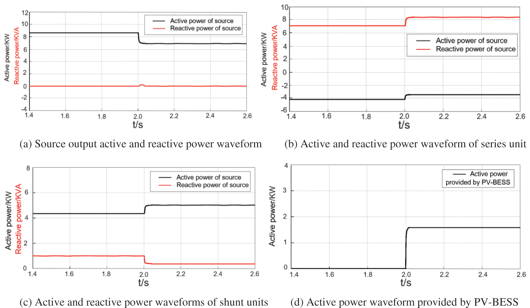
Figure 13: Active and reactive power waveforms of conventional compensation strategy
The simulation results using the compensation strategy proposed in this paper are shown in Fig. 14. When the system works normally, the grid provides all the active power 8.66 kW. The shunt unit provides all the reactive power 8.66 kVar to the load. The active power provided by the power supply is reduced to 1.48 kW after 2 s. The difference of active power 7.18 kW is provided by the energy storage unit to the load through the series and shunt units, as shown in Figs. 14a and 14d. Meanwhile, the active power provided by the series unit increases to 0.80 kW. The reactive power provided by the series unit increases to 1.25 kVar. The compensation capacity increases to 1.48 kVA after a voltage drop, as shown in Fig. 14b. The active power provided by the shunt unit increases to 0.79 kW. The reactive power provided by the shunt unit decreases to 7.41 kVar. The compensation capacity increases to 7.45 kVA after voltage drops in Fig. 14c. From the above simulation data, the total capacity provided by the system is 8.93 kVA.
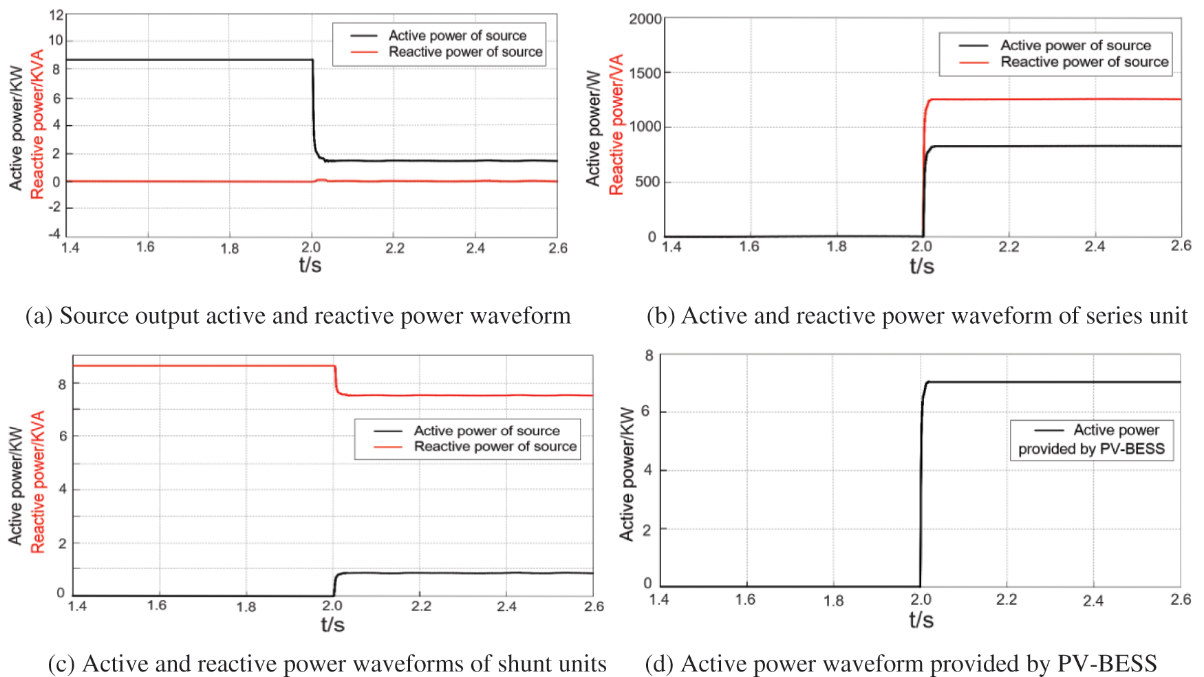
Figure 14: Active and reactive power waveforms of proposed compensation strategy
In order to further verify the function of UPQC with PV-BESS to supply continuous power to the load when the supply voltage drops completely under the proposed control strategy. The power supply is set to open circuit at 2 s. The system simulation results are shown in Figs. 15, 16a and 16b. As shown in Figs. 15, 16a and 16b, the series converter compensates the load voltage to the rated value with the amplitude of 310.26 V in the special case that the supply voltage drops to zero. It ensures the uninterrupted power supply to the load. Fig. 16b shows that the feeder current magnitude remains constant when the voltage drops completely. Figs. 17a–17d show that when the supply voltage is normal, the power supply assumes the full active power of the load of 8.66 kW. The series converter and shunt converter together assume the reactive power of 8.66 kVA. When the extreme case of the supply voltage drop occurs, the PV-BESS unit provides the full active power of the load. At which time the power of the load reactive unit is distributed in a coordinated manner.
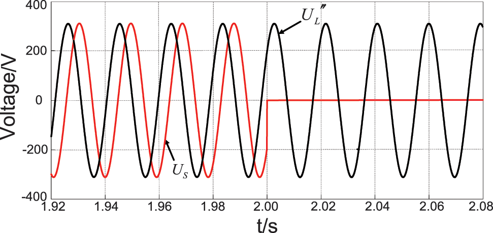
Figure 15: Conventional power angle compensation strategy supply voltage, load voltage waveform
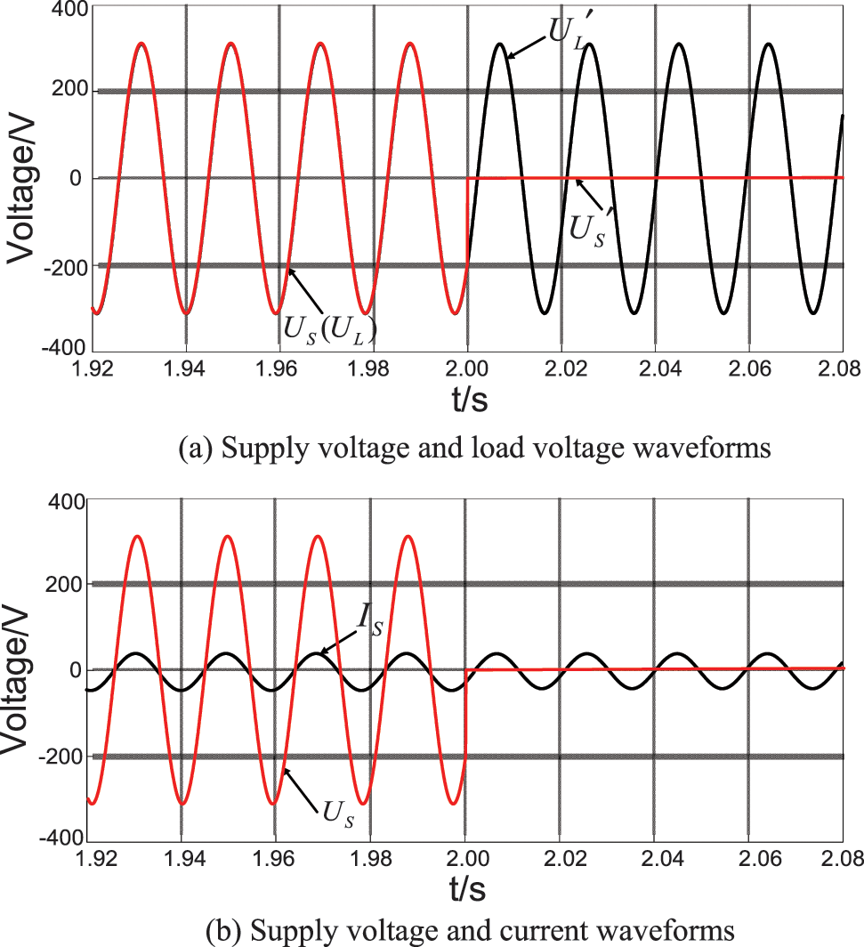
Figure 16: The proposed full load voltage compensation strategy supply voltage and load voltage waveforms (a), supply voltage and current waveforms (b)
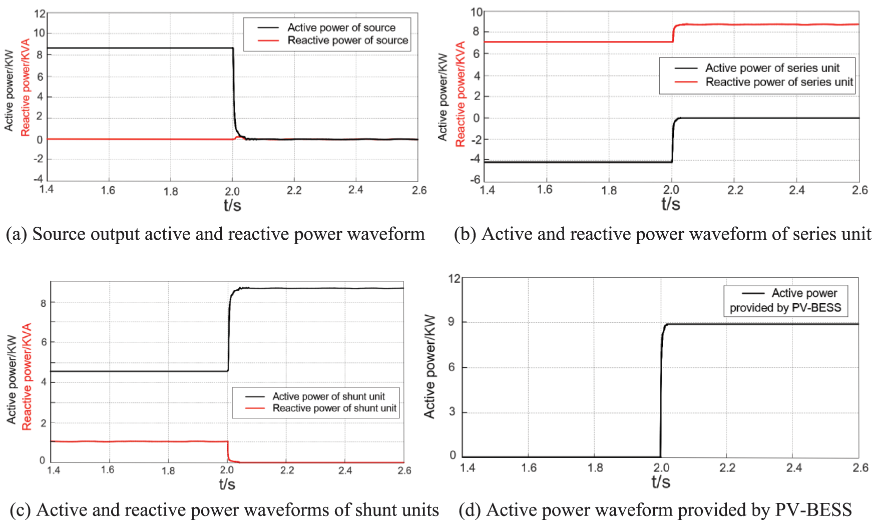
Figure 17: Active and reactive power waveforms of proposed compensation strategy
In summary, when in the case of a fault with a 20% drop in power supply voltage and a jump in phase. The proposed compensation strategy increases the compensation capacity of shunt units by 2.07 kVA compared to the conventional compensation strategy. But it reduces the compensation capacity of series units by 7.18 kVA. That results in a reduction of 5.11 kVA (36.4%) in the total system capacity. Therefore, the proposed compensation strategy reduces the capacity allocation of UPQC by reducing the compensation capacity of series units. The series converter compensates the load voltage to the rated value with the amplitude of 310.26 V in the special case that the supply voltage drops to zero. It ensures the uninterrupted power supply to the load. The PV-BESS unit provides the full active power of the load. At which time the power of the load reactive unit is distributed in a coordinated manner.
In this paper, a full load voltage compensation strategy in capacity configuration is proposed for PV-BESS-UPQC. The problems of phase jump and high compensation capacity of series units after the compensation strategy are pointed out. Then, the compensation strategies proposed in this paper are analyzed. Through the comparative analysis of the two compensation strategies, the main conclusions are as follows:
1) By reasonably distributing the power of UPQC series unit, shunt unit and PV-BESS unit, the capacity configuration of UPQC can be effectively reduced and the compensation performance of UPQC can be improved.
2) The PV-BESS unit is used to maintain the power supply current as the active component of the load current under normal conditions. It reduces the feeder current increased when the power supply voltage drops and eliminates the risk of feeder overcurrent in the distribution network.
3) In the special case that the power supply voltage drops to zero, the PV-BESS unit provides all the active power of the load at this time. It ensures the uninterrupted power supply to the load.
Funding Statement: Supported by Open Project of Jiangsu Key Laboratory of Power Transmission & Distribution Equipment Technology (2021JSSPD12) Supported by Talent Projects of Jiangsu University of Technology (KYY20018). Supported by Graduate Practice Innovation Program of Jiangsu University of Technology (XSJCX21_32).
Conflicts of Interest: The authors declare that they have no conflicts of interest to report regarding the present study.
References
1. Tan, Z., Luo, L. F., Cui, G. P., Hong, W. C., Tian, Y. (2020). UPQC with coupled controllable reactors. Electric Power Automation Equipment, 40(1), 101–105. [Google Scholar]
2. Huang, X. M., Fan, Z. H., Liu, Z. W., Miao, S., Li, X. W. et al. (2018). Control strategy of UPQC based on active and reactive power coordination distribution. Electric Power Automation Equipment, 38(3), 177–183. [Google Scholar]
3. Khadkikar, V. (2012). Enhancing electric power quality using UPQC: A comprehensive overview. IEEE Transactions on Power Electronics, 27(5), 2284–2297. [Google Scholar]
4. Khadem, S. K., Basu, M., Conlon, M. F. (2015). Intelligent islanding and seamless reconnection technique for microgrid with UPQC. IEEE Journal of Emerging & Selected Topics in Power Electronics, 3(2), 483–492. DOI 10.1109/JESTPE.2014.2326983. [Google Scholar] [CrossRef]
5. Khadem, S. K., Basu, M., Conlon, M. F. (2016). A comparative analysis of placement and control of UPQC in DG integrated grid connected network. Sustainable Energy, Grids and Networks, 6(1), 46–57. DOI 10.1016/j.segan.2016.02.003. [Google Scholar] [CrossRef]
6. Devassy, S., Singh, B. (2017). Design and performance analysis of three-phase solar PV integrated UPQC. IEEE Transactions on Industry Applications, 54(1), 73–81. [Google Scholar]
7. Campanhol, L. B. G., da Silva, S. A. O., de Oliveira, A. A., Bacon, V. D. (2019). Power flow and stability analyses of a multifunctional distributed generation system integrating a photovoltaic system with unified power quality conditioner. IEEE Transactions on Power Electronics, 34(7), 6241–6256. DOI 10.1109/TPEL.2018.2873503. [Google Scholar] [CrossRef]
8. Lakshmi, S., Ganguly, S. (2019). Multi-objective planning for the allocation of PV-BESS integrated open UPQC for peak load shaving of radial distribution networks. The Journal of Energy Storage, 22, 208–218. DOI 10.1016/j.est.2019.01.011. [Google Scholar] [CrossRef]
9. Goud, B. S., Rao, B. L. (2021). Power quality enhancement in grid-connected PV/wind/battery using UPQC: Atom search optimization. Journal of Electrical Engineering & Technology, 16(2), 821–835. DOI 10.1007/s42835-020-00644-x. [Google Scholar] [CrossRef]
10. Karanki, G., Mishra, M. K., Kumar, B. K. (2013). A modified three-phase four-wire UPQC topology with reduced DC-link voltage rating. IEEE Transactions on Industrial Electronics, 60(9), 3555–3566. DOI 10.1109/TIE.2012.2206333. [Google Scholar] [CrossRef]
11. Dash, S. K., Ray, P. K. (2018). Novel PV-tied UPQC topology based on a new model reference control scheme and integral plus sliding mode DC-link controller. International Transactions on Electrical Energy Systems, 28(2), e2564. DOI 10.1002/etep.2564. [Google Scholar] [CrossRef]
12. Reddy, P. M., Reddy, A. S., Sarvesh, B. (2021). Hybrid ANFIS-FA-based control strategy for UPQC-power quality enhancement in smart grid. International Journal of Power Electronics, 13(4), 399–433. DOI 10.1504/IJPELEC.2021.115580. [Google Scholar] [CrossRef]
13. Devassy, S., Singh, B. (2017). Modified pq-theory-based control of solar-PV-integrated UPQC-S. IEEE Transactions on Industry Applications, 53(5), 5031–5040. DOI 10.1109/TIA.2017.2714138. [Google Scholar] [CrossRef]
14. Lakshmi, S., Ganguly, S. (2020). Multi-objective planning for the allocation of PV-BESS integrated open UPQC for peak load shaving of radial distribution networks. The Journal of Energy Storage, 22(2), 208–218. DOI 10.1016/j.est.2019.01.011. [Google Scholar] [CrossRef]
15. Singh, M. K., Kumar, A., Gupta, A. R. (2022). Distribution system analysis with UPQC allocation considering voltage dependent time-variant and invariant loads including load growth scenario. Journal of the Institution of Engineers (IndiaSeries B, 103(3), 791–807. DOI 10.1007/s40031-021-00695-2. [Google Scholar] [CrossRef]
16. Feng, X. T., Zhang, L. X., Kang, Z. J. (2014). Working conditions and control strategy of UPQC based on supercapacitor energy storage. Electric Power Automation Equipment, 34(4), 84–89. [Google Scholar]
17. Patel, A., Mathur, H. D., Bhanot, S. (2020). Enhancing VA sharing between the shunt and series APFs of UPQC with a modified SRF‐PAC method. IET Power Electronics, 13(2), 275–285. DOI 10.1049/iet-pel.2018.6329. [Google Scholar] [CrossRef]
18. Patel, A., Yadav, S. K., Mathur, H. D., Bhanot, S., Bansal, R. C. (2020). Optimum sizing of PV based UPQC-DG with improved power angle control. Electric Power Systems Research, 182(7), 106259. DOI 10.1016/j.epsr.2020.106259. [Google Scholar] [CrossRef]
Cite This Article
 Copyright © 2023 The Author(s). Published by Tech Science Press.
This work is licensed under a Creative Commons Attribution 4.0 International License , which permits unrestricted use, distribution, and reproduction in any medium, provided the original work is properly cited.
 Downloads
 Citation Tools