
 Submit a Paper
 Propose a Special lssue
 Open Access
ARTICLE

Thermodynamic Analysis and Optimization of the C3/MRC Liquefaction Process
Oilfield Safety and Environmental Quality Management Department, Sinopec Shengli Oilfield Company, Dongying, 257001, China
* Corresponding Author: Guisheng Wang. Email:
(This article belongs to the Special Issue: Multiphase Flow Theory in Oil and Gas Gathering and Transportation Process)
Energy Engineering 2023, 120(6), 1503-1514. https://doi.org/10.32604/ee.2023.027416
Received 28 October 2022; Accepted 27 December 2022; Issue published 03 April 2023
 View Full Text
 Download PDF
Abstract
In the natural gas liquefaction process, the mixed refrigerant natural gas liquefaction process is widely used in LNG liquefaction plants because of its advantages of low energy consumption. This paper focuses on the influences of important parameters in the C3/MRC liquefaction process, that is, the comparison between propane precooling temperature and the number of moles of methane in mixed refrigerant, power consumption and loss. In addition, the total process was optimized with the optimizer and manual adjustment in HYSYS software to minimize the total power consumption. The results show that with increasing propane precooling temperature, the propane flow rate is almost unchanged, while the mixed refrigerant flow rate decreases significantly, and the loss of the heat exchanger increases significantly. The power consumption of the propane precooling cycle and hybrid refrigeration cycle increases with increasing methane content in the refrigerant, so the power consumption of the whole process increases accordingly. The effect of the methane content in the mixed refrigerant on the process evaluation index is more significant than that of the propane precooling temperature.Keywords
Growing concerns for global warming and the rapid depletion of other fossil fuels have put natural gas at the forefront of sustainable energy. The transportation of processed natural gas from the gas field to the market is a fundamental step in the gas value chain. LNG accounts for approximately 30% of natural gas transportation from field to consumer markets, especially far-reaching sea and remote gas fields. Consequently, the demand for natural gas liquefaction technology is increasing. In response to this need, there has been tremendous research in cryogenic engineering in the past few decades, leading to the development of specialized refrigeration cycles for LNG production, such as nitrogen (N2) recycle, nitrogen recycle with hydrofluorocarbon (HFC) precooling, single mixed refrigerant (SMR) cycle, dual mixed refrigerant (DMR) cycle, and propane precooled mixed refrigerant (C3MR) cycle. Nitrogen-based cycles, although relatively simple in configuration and safe and flexible in operation, have been faced out due to their low energy efficiency [1–3]. Mixed refrigerant cycles deliver much higher energy efficiencies. In recent years, to simplify the liquefaction process, supersonic cyclone technology was introduced into the natural gas liquefaction process [4–7]. On the whole, SMR is famous among small- and medium-scale LNG plant operators due to its simplicity and flexibility of operation, small equipment size, and low cost [8–10].
The design of any physical and profitable system involves some key variables (controlled and uncontrolled) that fulfill the system requirements or characteristics, which are defined beforehand by an end user (customer). In the case of LNG plant design, the highest performance in terms of low energy consumption with the highest possible liquefaction rate (i.e., usually greater than 90%) is considered the major requirement and objective. The design of an LNG plant can be considered “optimal” if it achieves the objective in terms of energy efficiency. The process of searching for the optimal values of the design variables for any well-defined system is known as “optimization”.
Much research has been carried out in terms of process modifications. Tak et al. [11] studied the effect of a multistage compression system on the performance of a single mixed refrigerant liquefaction process. Twelve cases were developed based on the compressor configuration and natural gas composition. The results revealed that the mixed refrigerant composition did not significantly change with different compression configurations and that the specific energy consumption was affected by only 1%–2% of its mixed refrigerant composition values by different design bases. An exergoeconomic analysis of two novel systems for the coproduction of LNG and NGL was carried out by Won et al. [12]. They reported that the cost of exergy loss is avoidable for turbo expanders and compressors but unavoidable for heat exchangers and air coolers. Ansarinasab et al. [13] proposed a novel energy efficient operating system for the natural gas liquefaction process. The proposed scheme was tested on a simulated 100-ton-per-day LNG plant, and an energy savings of 259.7 kJ was reported relative to the worst feasible case.
Many scholars also focus on the optimization of operating conditions and refrigerant composition. Lee et al. [14] proposed a novel approach for the selection of refrigerant compositions for nonazeotropic refrigerant mixtures through the combination of thermodynamics and nonlinear programming techniques. Taking the pressure levels of the compressor, refrigerant flow rate, and refrigerant composition as key design variables, a systematic design method of MR systems was established. A case study of the PRICO SMR process was simulated using STAR software, and energy savings of up to 25% were reported. Khan et al. [15] described a knowledge-based optimization scheme for the selection of mixed refrigerants and determination of their compositions, taking minimum compressor shaft work and maximum process energy efficiency as optimization objectives for SMR and C3MR refrigeration cycles. Xu et al. [16] studied the correlation between mixed refrigerant composition and ambient temperature in the PRICO LNG process. Using a genetic algorithm coupled to Aspen HYSYS simulation software, they optimized the MR composition at varying ambient temperatures and reported that an increase in ambient temperature demands an increase in the concentration of isopentane and a corresponding decrease in the concentrations of methane, ethylene and propane. Fan et al. [17] conducted energy-saving optimization on an SMR process plant taking the temperature and pressure of mid- and high-pressure refrigerants as independent variables and unit energy consumption as an objective parameter. A quadratic regression orthogonal design was employed, and an energy savings of 5.54% with respect to the base case was reported.
In summary, optimization of liquefaction, process operating conditions and refrigerant composition has been studied by many researchers. However, there is a lack of systematic research to evaluate the effects of the propane precooling temperature and the number of moles of methane in mixed refrigerant on the liquefaction performance of the mixed refrigerant liquefaction process with propane precooled (C3/MRC). In this paper, the influence and optimization of important parameters on evaluation indices in the C3/MRC process were carried out by using the process simulation HYSYS software.
2 Process Flow of the C3/MRC Process
2.1 Process Flow Establishment
The mixed refrigerant (MR) liquefaction process overcomes the problem of high equipment inventory by combining all refrigerants in one or two refrigeration cycles. In this process, different refrigerants are combined to form a single stream of MR, which is compressed, cooled, and expanded to provide cold energy for the cooling and liquefaction of the natural gas stream. The MR components and their compositions are carefully selected to ensure that the heat composite curve of the MR closely matches that of the natural gas stream. Common refrigerants used in the MR liquefaction process include nitrogen, methane, ethane, ethylene, propane, isobutene, normal butane, isopentane, and normal pentane. Some MR liquefaction processes include a precooling cycle that utilizes a separate refrigerant. A good example is the famous propane precooled mixed refrigerant process (C3/MRC) licensed by Air Products and Chemical Incorporated. Unlike other liquefaction processes where evaporation of refrigerant in a heat exchanger occurs at a constant temperature, in the MR process, the refrigerant mixture boils over a temperature range that could be optimized to suit the heat composite curve of natural gas, leading to high energy efficiencies at comparatively lower inventory costs [18,19]. The natural gas liquefaction process simulated in this paper is shown in Fig. 1.
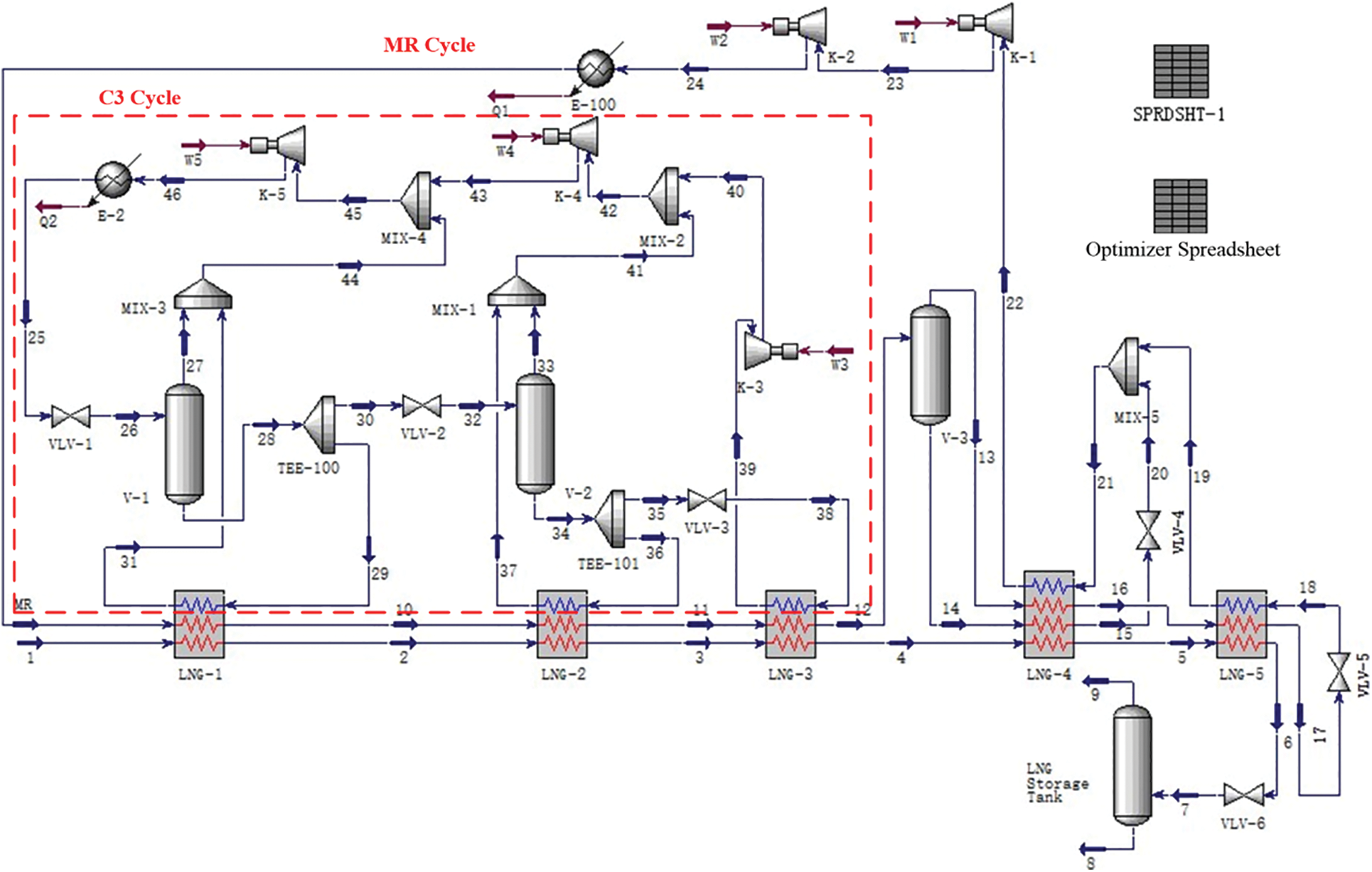
Figure 1: Simulation flow chart established by HYSYS software
2.2 Process Initial and Equipment Process Parameters
When establishing the simulation process, the propane precooling cycle is first established and polymerized, and then the mixed refrigerant cycle is established and polymerized. The natural gas liquefaction circuit will be completed once both procedures are completed. The pressure drop of the cooler and LNG heat exchanger is set to 20 kPa to simplify the model by taking into account the actual pressure drop. The variable efficiency of the compressor is considered to be 75%.
For the propane precooling cycle, the temperature of stream 25 of high-pressure propane after water cooling is first determined. Considering that the temperature of the cooling water is close to the ambient temperature, 40°C is assumed. Latent heat is considered the main source of cooling capacity in the propane precooling cycle unit. Therefore, high-pressure propane at 40°C should be liquid. Considering that the pressure of propane is 1.37 MPa when the bubble point temperature is 40°C, the pressure of high-pressure propane is set as 1.4 MPa. For each propane evaporator, the outlet temperature of each heat flow should be set. Considering that the outlet streams of the propane evaporator are equal in actual production, the outlet temperature difference between heat flows should also be set to 0 through the specified options in the heat exchanger in this simulation process. The outlet temperature of the hot stream is initially set to −2°C, −20°C and −37°C. In addition, the following two aspects should be considered: ① Since only the latent heat of propane is used, the gas phase fraction of stream 31 at the outlet of the cold streams is set to 1; ② To set the pinch point temperature of the cooling and heating curve in the heat exchanger to 3°C, the temperature of stream 26 behind the throttle valve should be 3°C lower than the temperature of thermal stream 2 at the outlet of the heat exchanger. The linear relationship between the two temperatures is set through the set module.
For the mixed refrigerant cycle, the temperature and pressure of the streams MR after compression by the compressor and cooling by the cooler are first determined: their values are set to 40°C and 2.5 MPa, respectively. The outlet heat flow temperature of each LNG heat exchanger is set equally, and the outlet temperatures are −115°C and −152°C. Considering the pressure of the low-pressure refrigerant in the partial thermodynamic analysis of the process, the pressure of stream 22 is set to 0.27 MPa. Under this pressure, the gas phase fraction shall be 1 to avoid a liquid hammer in the compressor.
The refrigerant components commonly used in natural gas liquefaction systems are N2 and C1–C5. It can be deduced from the properties of pure refrigerant in Table 1 that the boiling point and gasification latent heat of refrigerant components increase with the increase in relative molecular weight, and the refrigeration temperature zone also moves to a higher temperature zone. The difference in the gasification latent heat values of mixed refrigerants under low and high pressures provides the cooling capacity required for natural gas liquefaction. Therefore, when selecting refrigerants, priority should be given to components with large gasification latent heat differences.
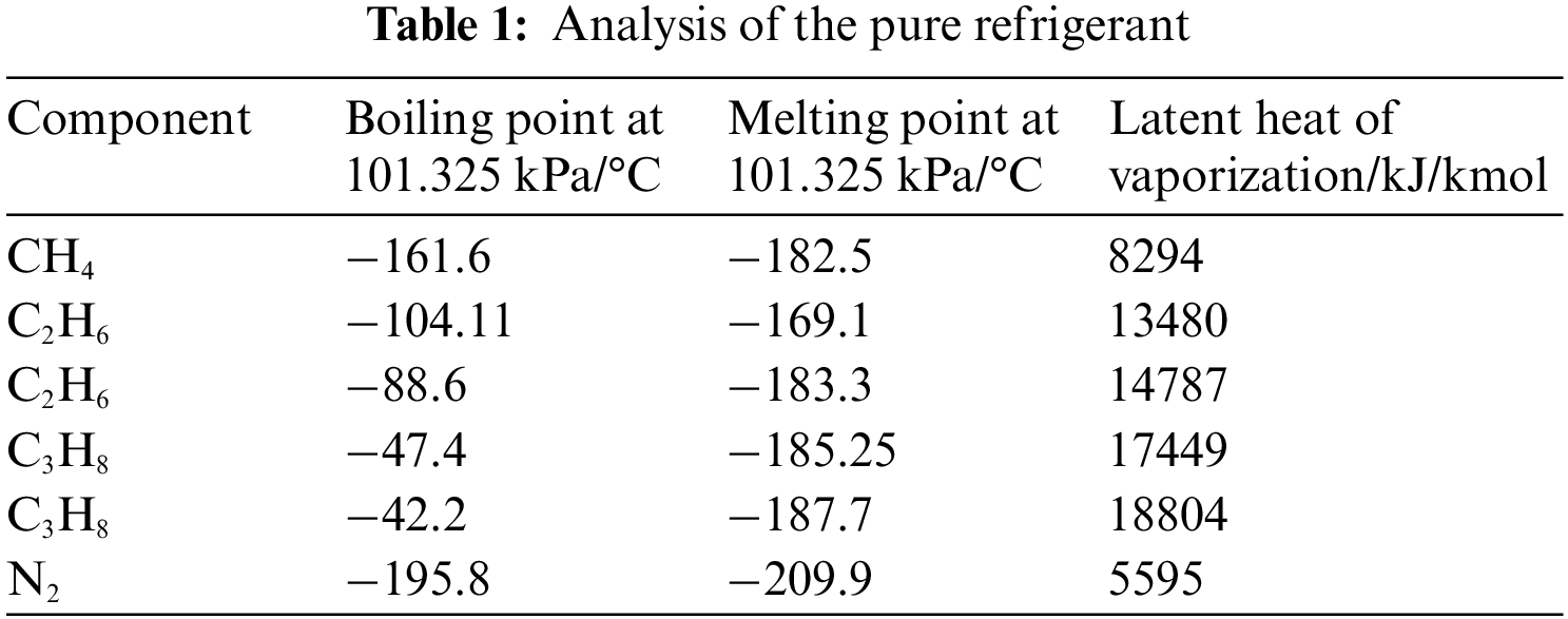
To meet the requirements of conventional natural gas liquefaction, the selected refrigerant needs to cover the temperature range of −180°C~20°C. The C3/MRC process can be divided into propane precooling cycles and mixed refrigerant cryogenic cycles. The refrigerant component of the precooling cycle is propane, and the feed gas needs to be cooled from 25°C to −35°C. The feed gas needs to be cooled from −35°C to −162°C for the cryogenic cycle. Table 1 shows that the refrigerant components are N2 and C1–C3 to meet the requirements.
All processes of the system are in a steady state, and the kinetic and potential energy effects are ignored. Except for compressors, pumps and expanders, pressure losses in other components are neglected [20]. The conversion between electrical energy and mechanical energy is 100% [21,22].
3 Influence and Optimization of Important Parameters on Evaluation Indices in the C3/MRC Process
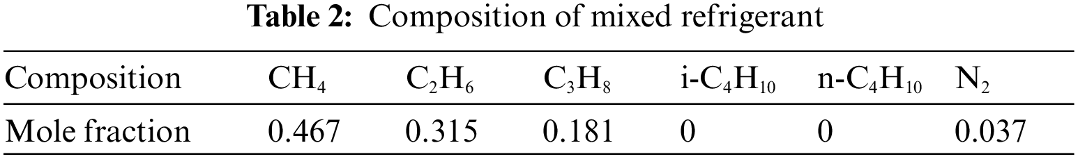
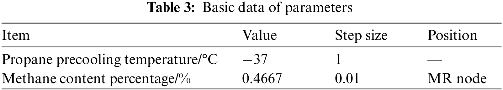
This paper focuses on the influences of important parameters in the C3/MRC process, that is, the comparison between the propane precooling temperature and the number of moles of methane in mixed refrigerant, power consumption and loss. When analyzing the parameters, the control variable method is adopted: only the size of the parameters involved in the analysis process is changed, and the other parameters remain unchanged. The flow of mixed refrigerant is 3526 kmole/h, and the composition is shown in Table 2. The selected initial values of the parameters and the positions of the parameters and nodes are shown in Table 3.
3.1 Influence of Propane Precooling Temperature on Process Evaluation Index
The propane precooling temperature refers to the temperature of natural gas and mixed refrigerant passing through the third-stage propane evaporator. The temperature of the mixed refrigerant and natural gas after propane precooling was previously studied. In actual production, the streams at the outlet of the heat exchanger are generally equal. Therefore, this paper treats the two as the same variable. At the same time, to validate that the temperature difference between the cold and hot flow of the first LNG heat exchanger in the third-stage propane evaporator and mixed refrigerant cycle is 3°C, the propane inlet temperature of the third-stage propane evaporator and the temperature of the low-pressure mixed refrigerant were also changed while modulating the propane precooling temperature. In short, when studying the influence of the propane precooling temperature on the process evaluation indices, the inlet temperature of propane in the third-stage propane evaporator and the outlet temperature of natural gas and mixed refrigerant should be consistent.
As shown in Fig. 2, with increasing propane precooling temperature, the propane flow rate is almost unchanged, while the mixed refrigerant flow rate decreases significantly. This is because the cooling capacity of natural gas in the propane cycle is reduced, and the cooling capacity required in the mixed refrigerant cycle is increased, which increases the flow of mixed refrigerant.
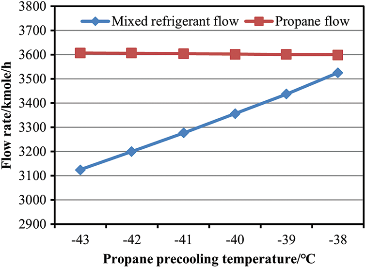
Figure 2: Effect of propane precooling temperature on flow
As shown in Fig. 3, with increasing propane precooling temperature, although the power consumption of the propane precooling cycle decreases, the power consumption of the whole process increases with increasing power consumption in the mixed refrigerant cycle. Therefore, the temperature of natural gas and high-pressure mixed refrigerant entering the mixed refrigeration process should be reduced as much as possible, which is the purpose of increasing the propane precooling cycle.
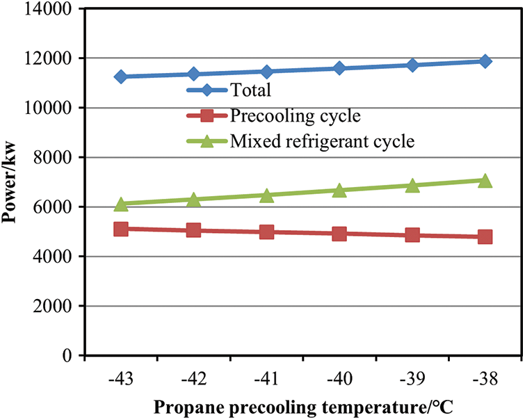
Figure 3: Effect of the propane precooling temperature on the power consumption
As shown in Fig. 4, with the increase in propane precooling temperature, the loss of the throttle valve, mixer and compressor does not change significantly, but the loss of the heat exchanger increases significantly. This is because when the precooling temperature decreases, a principle similar to the step refrigeration cycle can make the cold and heat composite curves of the entire logistical process closer by reducing the heat transfer temperature difference and reducing the irreversible loss of the heat transfer process. Increasing the precooling cycle is also an effective way to reduce heat loss.
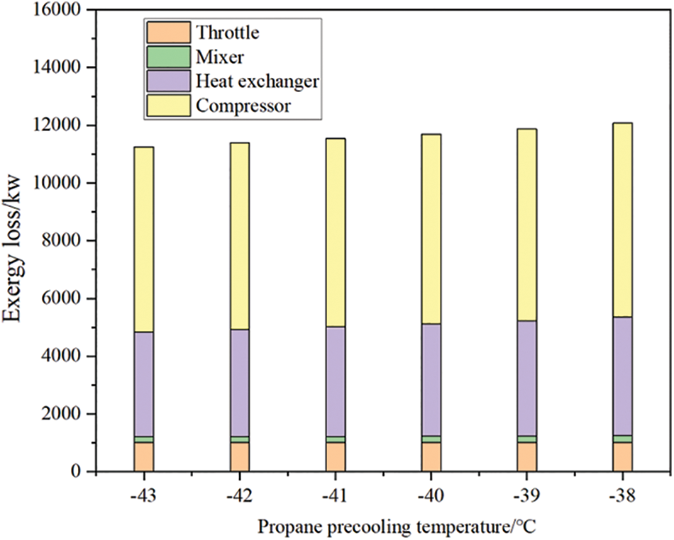
Figure 4: Effect of the propane precooling temperature on the loss
3.2 Influence of Methane Content in Mixed Refrigerant on Process Evaluation Index
As shown in Fig. 5, the increase in the proportion of methane content in the mixed refrigerant will increase the flow of both refrigerants, and the flow of the mixed refrigerant will increase at a greater rate. Therefore, the proportion of methane in the mixed refrigerant should be reduced as much as possible. On the other hand, increased methane content in the mixed refrigerant leads to greater difficulty of liquefaction, which increases the refrigerant flow required in the propane precooling cycle.
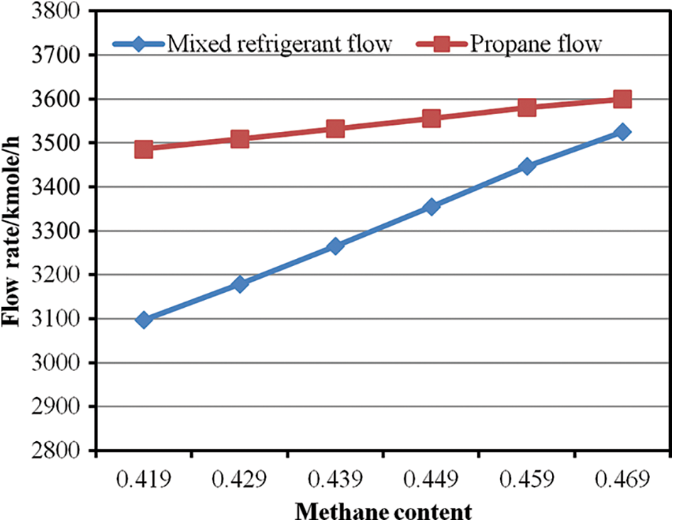
Figure 5: Effect of methane content in mixed refrigerant on flow
As shown in Fig. 6, the power consumption of the propane precooling cycle and hybrid refrigeration cycle increases with increasing methane content in the refrigerant, so the power consumption of the whole process increases accordingly. The increase in power consumption is largely due to the increase in refrigerant flow. Reducing the content of methane in the mixed refrigerant plays an important role in optimizing the process.
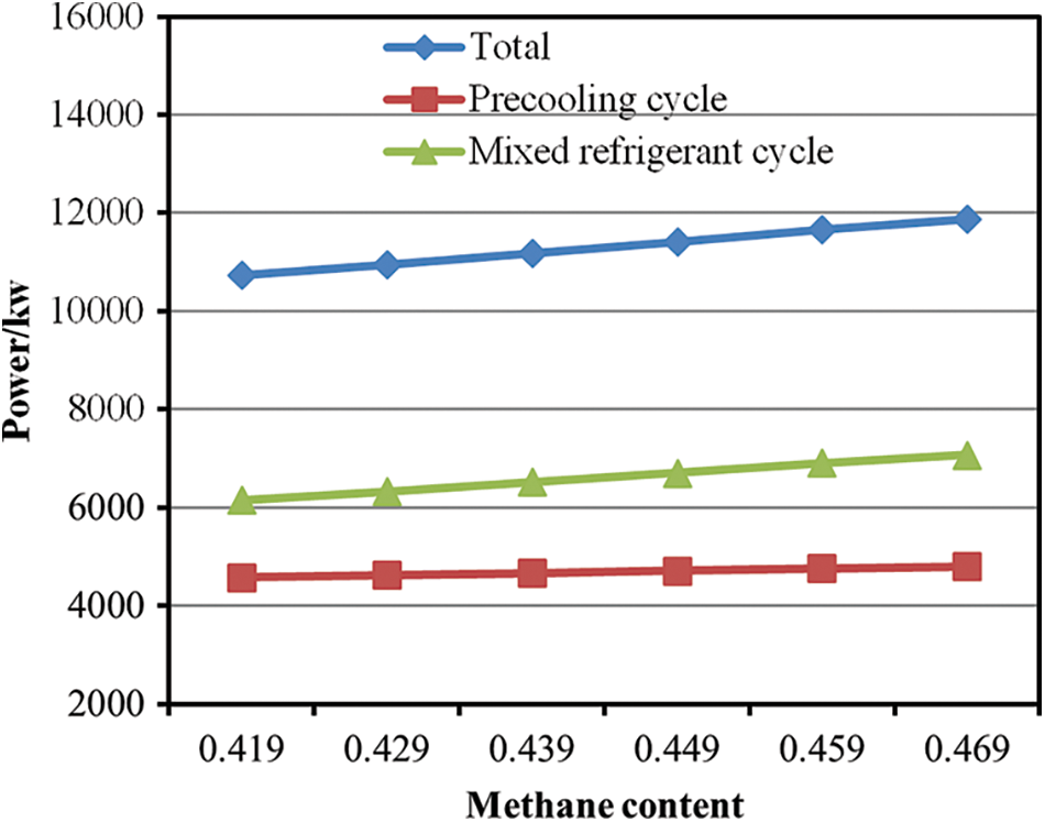
Figure 6: Effect of methane content in mixed refrigerant on power consumption
As shown in Fig. 7, with the increase in methane content in the mixed refrigerant, the loss of the compressor and heat exchanger increases significantly, while the loss of the throttle valve and mixer decreases within a small range, and the corresponding loss of the whole process also increases. The increase in compressor loss is mainly related to the increase in compressor power consumption. The increase in heat loss in the heat exchanger is due to the temperature difference between the cooling and heating load curves in the heat exchanger.
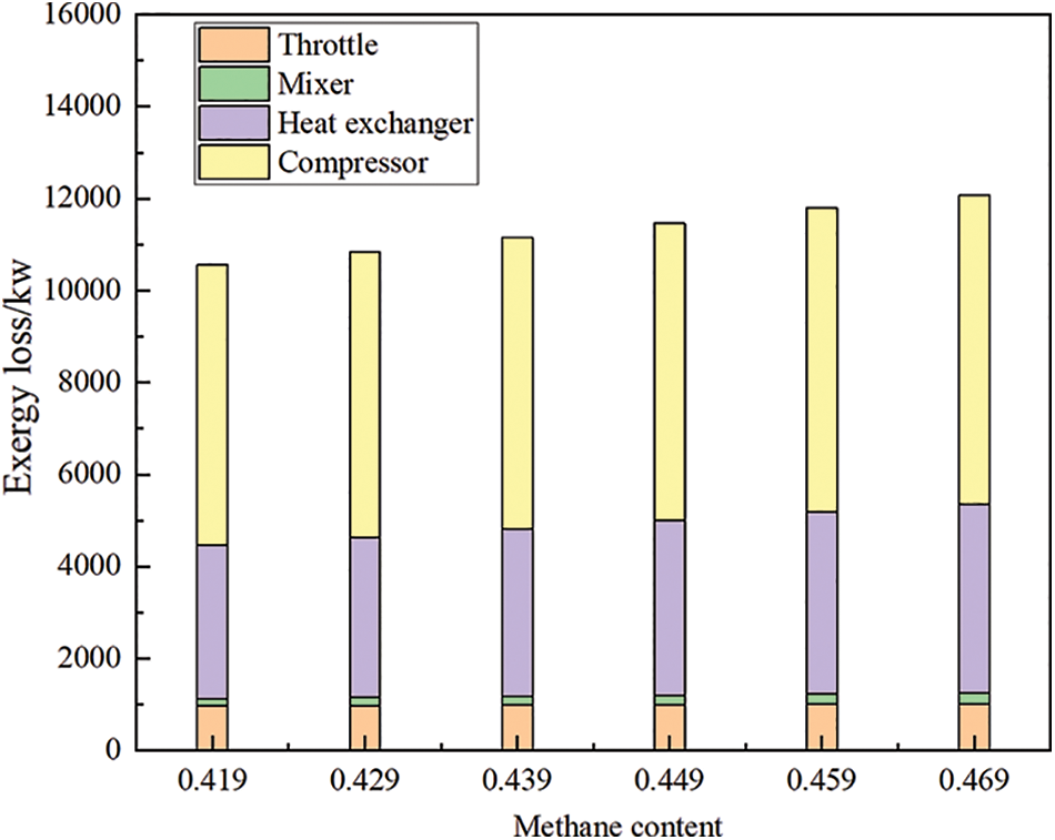
Figure 7: Effect of methane content in mixed refrigerant on gas loss
3.3 Parameter Optimization of the C3/MRC Liquefaction Process
From the influences of important parameters in the process on the evaluation index, it can be found that the change trends of compressor power consumption, heat exchanger loss, and compressor loss correspond with that of the whole process. The decrease in propane precooling temperature and the decrease in methane content in the mixed refrigerant will reduce the power consumption and loss of the entire process. The heat loss of the heat exchanger is mainly caused by irreversible heat transfer between different temperatures. The loss calculation formula of the irreversible heat transfer process is shown in Eq. (1):
In Eq. (1),
From Eq. (1), it can be determined that the two factors primarily affecting the heat loss are the heat exchange and heat transfer temperature difference. Because there are many devices involved in the process and the calculation process is complex, the total specific power consumption of the process is only composed of the specific power consumption of five compressors. Therefore, when optimizing the total process with the optimizer and manual adjustment in HYSYS software (because it is impossible to adjust the methane content in the mixed refrigerant with the optimizer), the objective function is set to minimize the total power consumption.
The constraints of the optimization process are as follows: ① The minimum temperature difference between LNG-4 and LNG-5 is 3°C (the other three heat exchangers have a minimum temperature difference set to 3°C through the set module); ② When the low-pressure mixed refrigerant enters the compressor, the gas phase fraction is 1 (the gas phase fraction of the streams at the compressor inlet in the propane precooling process has been set to 1 through the variable).
In the optimization process, the above variables are set as the only variables to optimize the process first in order to analyze the change to the process optimization that can result from the change of a single parameter. The results are shown in Table 4:
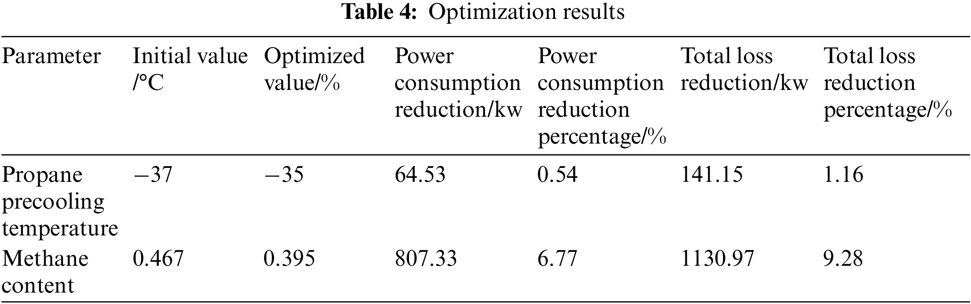
From the above results, it can be found that optimizing the composition of mixed refrigerant has the most obvious effect on the reduction of process power consumption and total loss. The effect of the methane content in the mixed refrigerant on the process evaluation index is more significant than that of the propane precooling temperature.
The compound curve of hot and cold fluids in the heat exchanger can be used as a thermodynamic tool to evaluate the heat exchange efficiency of the heat exchanger. For the liquefaction process with low specific energy consumption, the compound curve in the heat exchanger should be as close as possible. The composite curves with respect to heat flow and temperature for the heat exchangers are shown in Fig. 8 (LNG-1 and LNG-4 were taken as examples). The logarithmic average temperature difference of the overall heat transfer is generally low, which means that the selected flow parameters can maintain good performance of the heat exchanger and the liquefaction system.
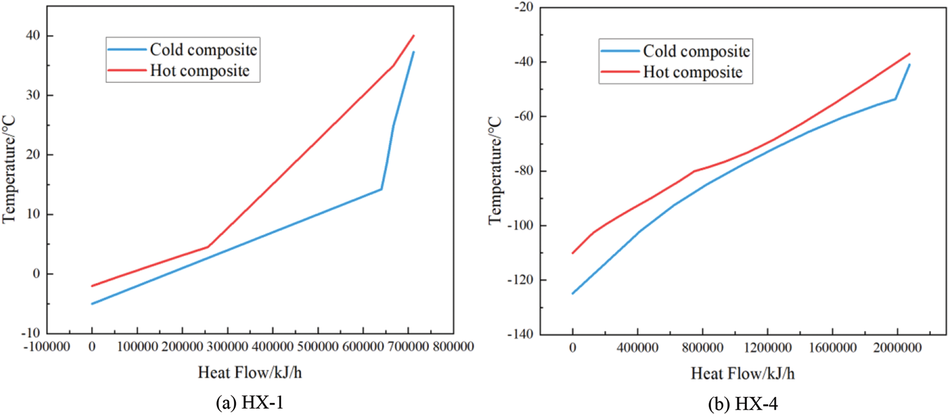
Figure 8: The composite curves with respect to heat flow and temperature for the heat exchangers
In this paper, the influence and optimization of important parameters on evaluation indices in the C3/MRC process were carried out by using the process simulation HYSYS software. The main conclusions are as follows:
(1) With increasing propane precooling temperature, the power consumption of the whole process increases with increasing power consumption in the mixed refrigerant cycle, and the loss of the throttle valve, mixer and compressor does not change significantly, but the loss of the heat exchanger increases significantly.
(2) The power consumption of the propane precooling cycle and hybrid refrigeration cycle increases with increasing methane content in the refrigerant, so the power consumption of the whole process increases accordingly. With the increase in methane content in the mixed refrigerant, the loss of the compressor and heat exchanger increases significantly, while the loss of the throttle valve and mixer decreases within a small range, and the corresponding loss of the whole process also increases.
(3) Optimizing the composition of mixed refrigerant has the most obvious effect on the reduction of process power consumption and total loss. The effect of the methane content in the mixed refrigerant on the process evaluation index is more significant than that of the propane precooling temperature.
Funding Statement: This work was supported by the Research Project of Sinopec Shengli Oilfield Company “Research of Energy Flow Optimization Analysis and Application Technology of Oilfield Production System”.
Conflicts of Interest: The author declares that they have no conflicts of interest to report regarding the present study.
References
1. He, T., Liu, Z., Ju, Y., Parvez, A. M. (2019). A comprehensive optimization and comparison of modified single mixed refrigerant and parallel nitrogen expansion liquefaction process for small-scale mobile LNG plant. Energy, 167(15), 1–12. https://doi.org/10.1016/j.energy.2018.10.169 [Google Scholar] [CrossRef]
2. Ferreira, P. A., Catarino, I., Vaz, D. (2017). Thermodynamic analysis for working fluids comparison in Rankine-type cycles exploiting the cryogenic exergy in liquefied natural gas (LNG) regasification. Applied Thermal Engineering, 121, 887–896. https://doi.org/10.1016/j.applthermaleng.2017.04.082 [Google Scholar] [CrossRef]
3. Wu, X., Wang, Z., Dong, M., Dong, L., Ge, Q. (2022). A critical analysis of natural gas liquefaction technology. Fluid Dynamics & Materials Processing, 18(1), 145–158. https://doi.org/10.32604/fdmp.2022.018227 [Google Scholar] [CrossRef]
4. Bian, J., Cao, X. W., Yang, W., Edem, M. A., Yin, P. B. et al. (2018). Supersonic liquefaction properties of natural gas in the Laval nozzle. Energy, 159, 706–715. https://doi.org/10.1016/j.energy.2018.06.196 [Google Scholar] [CrossRef]
5. Bian, J., Cao, X. W., Yang, W., Guo, D., Xiang, C. C. (2020). Prediction of supersonic condensation process of methane gas considering real gas effects. Applied Thermal Engineering, 164, 114508. https://doi.org/10.1016/j.applthermaleng.2019.114508 [Google Scholar] [CrossRef]
6. Bian, J., Cao, X. W., Yang, W., Song, X. D., Xiang, C. C. et al. (2019). Condensation characteristics of natural gas in the supersonic liquefaction process. Energy, 168, 99–110. https://doi.org/10.1016/j.energy.2018.11.102 [Google Scholar] [CrossRef]
7. Cao, X., Bian, J. (2019). Supersonic separation technology for natural gas processing: A review. Chemical Engineering and Processing-Process Intensification, 136, 138–151. https://doi.org/10.1016/j.cep.2019.01.007 [Google Scholar] [CrossRef]
8. Le, C., Liu, J., Xu, X. (2016). Robustness analysis of the mixed refrigerant composition employed in the single mixed refrigerant (SMR) liquefied natural gas (LNG) process. Applied Thermal Engineering, 93, 1155–1163. https://doi.org/10.1016/j.applthermaleng.2015.10.072 [Google Scholar] [CrossRef]
9. Chang, H. M., Lim, H. S., Choe, K. H. (2012). Effect of multi-stream heat exchanger on performance of natural gas liquefaction with mixed refrigerant. Cryogenics, 52(12), 642–647. https://doi.org/10.1016/j.cryogenics.2012.05.014 [Google Scholar] [CrossRef]
10. Pozo, C., Lvaro, N. J., Martín, J. R., Paniagua, I. L. (2021). Efficiency evaluation of closed and open cycle pure refrigerant cascade natural gas liquefaction process through exergy analysis. Journal of Natural Gas Science and Engineering, 89(1), 103868. https://doi.org/10.1016/j.jngse.2021.103868 [Google Scholar] [CrossRef]
11. Tak, K., Lee, I., Kwon, H., Ko, D., Moon, I. (2015). Comparison of multistage compression configurations for single mixed refrigerant processes. Industrial & Engineering Chemistry Research, 54(41), 9992–10000. https://doi.org/10.1021/acs.iecr.5b00936 [Google Scholar] [CrossRef]
12. Won, W., Lee, K. S. (2017). An energy-efficient operation system for a natural gas liquefaction process: Development and application to a 100 ton-per-day plant. Computers & Chemical Engineering, 97, 208–219. https://doi.org/10.1016/j.compchemeng.2016.11.046 [Google Scholar] [CrossRef]
13. Ansarinasab, H., Mehrpooya, M. (2017). Evaluation of novel process configurations for coproduction of LNG and NGL using advanced exergoeconomic analysis. Applied Thermal Engineering, 115, 885–898. https://doi.org/10.1016/j.applthermaleng.2017.01.019 [Google Scholar] [CrossRef]
14. Lee, G. C., Smith, R., Zhu, X. X. (2002). Optimal synthesis of mixed-refrigerant systems for low-temperature processes. Industrial & Engineering Chemistry Research, 41(20), 5016–5028. https://doi.org/10.1021/ie020057p [Google Scholar] [CrossRef]
15. Khan, M. S., Lee, M. (2013). Design optimization of single mixed refrigerant natural gas liquefaction process using the particle swarm paradigm with nonlinear constraints. Energy, 49(12), 146–155. https://doi.org/10.1016/j.energy.2012.11.028 [Google Scholar] [CrossRef]
16. Xu, X., Liu, J., Jiang, C., Le, C. (2013). The correlation between mixed refrigerant composition and ambient conditions in the prico LNG process. Applied Energy, 102, 1127–1136. [Google Scholar]
17. Fan, Z., Pan, J. I., Lin, L., Liu, Z., Jing, X. Y. et al. (2018). System simulation and energy saving optimization of natural gas liquefaction process. Modern Chemical Industry, 38(9), 219–223. [Google Scholar]
18. Bian, J., Yang, J., Liu, Y., Li, Y. X., Cao, X. W. (2022). Analysis and efficiency enhancement for energy-saving re-liquefaction processes of boil-off gas without external refrigeration cycle on LNG carriers. Energy, 239, 122082. [Google Scholar]
19. Bian, J., Yang, J., Li, Y. X., Chen, Z. Q., Liang, F. C. et al. (2021). Thermodynamic and economic analysis of a novel hydrogen liquefaction process with LNG precooling and dual-pressure Brayton cycle. Energy Conversion and Management, 250, 114904. [Google Scholar]
20. Qyyum, M. A., Qadeer, K., Lee, M. (2018). Closed-loop self-cooling recuperative N2 expander cycle for the energy efficient and ecological natural gas liquefaction process. ACS Sustainable Chemistry and Engineering, 6, 5021–5033. [Google Scholar]
21. Ferreira, P. A., Catarino, I., Vaz, D. (2017). Thermodynamic analysis for working fluids comparison in Rankine-type cycles exploiting the cryogenic exergy in liquefied natural gas (LNG) regasification. Applied Thermal Engineering, 121, 887–896. https://doi.org/10.1016/j.applthermaleng.2017.04.082 [Google Scholar] [CrossRef]
22. Cao, X. W., Yang, J., Zhang, Y., Gao, S., Bian, J. (2022). Process optimization, exergy and economic analysis of boil-off gas reliquefaction processes for LNG carriers. Energy, 242(2), 122947. https://doi.org/10.1016/j.energy.2021.122947 [Google Scholar] [CrossRef]
Cite This Article
 Copyright © 2023 The Author(s). Published by Tech Science Press.
This work is licensed under a Creative Commons Attribution 4.0 International License , which permits unrestricted use, distribution, and reproduction in any medium, provided the original work is properly cited.
 Downloads
 Citation Tools