
 Submit a Paper
 Propose a Special lssue
 Open Access
ARTICLE

Effect of Intake Conditions and Nozzle Geometry on Spray Characteristics of Group-Hole Nozzle
School of Energy and Power Engineering, Jiangsu University, Zhenjiang, 212013, China
* Corresponding Author: Jianfeng Pan. Email:
Energy Engineering 2023, 120(7), 1541-1562. https://doi.org/10.32604/ee.2023.027873
Received 18 November 2022; Accepted 12 January 2023; Issue published 04 May 2023
 View Full Text
 Download PDF
Abstract
The group-hole nozzle concept is proposed to meet the requirement of nozzle hole minimization and reduce the negative impact of poor spatial spray distributions. However, there are limited researches on the effects of intake conditions and nozzle geometry on spray characteristics of the group-hole nozzle. Therefore, in this study, an accurate spray model coupled with the internal cavitating flow was established and computational fluid dynamics (CFD) simulations were done to study the effects of intake conditions and nozzle geometry on spray characteristics of the group-hole nozzle. Experimental data obtained using high-speed digital camera on the high-pressure common rail injection system was used to validate the numerical model. Effects of intake conditions (injection pressure and temperature) and nozzle geometry (orifice entrance curvature radius and nozzle length) on the flow and spray characteristics of the group-hole nozzle were studied numerically. The differences in Sauter mean diameter (SMD), penetration length and fuel evaporation mass between single-hole nozzle and group-hole nozzle under different nozzle geometry were also discussed. It was found that the atomization performance of the group-hole nozzle was better than that of the single-hole nozzle under same intake conditions, and the atomization effect of the short nozzle was better than that of the long nozzle. With increase in the orifice entrance curvature radius, the average velocity and turbulent kinetic energy of the fuel increased, which was conducive to improving the injection rate and flow coefficient of the nozzle. Meanwhile, the penetration length and SMD value rose, while evaporation mass dropped. When the ratio of the orifice entrance curvature radius (R) to the diameter of injection hole (D) was 0.12, the spray characteristics reached a constant state due to elimination of cavitation. Conclusions were made based on these. This study is expected to be a guide for the design of the group-hole nozzle.Keywords
Nomenclature
| D | Nozzle hole diameter (mm) |
| L | Nozzle length (mm) |
| R | Orifice entrance curvature radius (mm) |
| SMD | Sauter mean diameter |
| tbreak | Break-up time |
| ∆P | The difference between injection pressure and ambient pressure |
| ρg | Gas density |
| ρl | Fuel density |
Diesel engine plays a significant role in the field of internal combustion engine. Compared to other power machinery, it is widely used in diesel locomotives, ships and other transportation equipment because of its high power and good economy. However, the exhaust of diesel engine contain harmful emissions such as NOX and soot, which is a challenge to meet strict emission regulations [1,2]. Therefore, new technologies are urgently needed to meet this challenge. High-pressure common rail injection technology is an effective method to solve this problem, which can improve atomization quality of diesel to achieve more efficient and cleaner combustion of diesel engines [3].
The key component of the common rail injection system is the injector, which plays a vital role in the internal flow characteristics and fuel atomization of the diesel engine [4]. And the main part of the injector is the nozzle hole. The study of nozzle spray characteristics can be used to guide the design of injector geometry, which can lead to better atomization and cleaner combustion of diesel fuel [5,6]. Therefore, it is of great significance to study the flow and spray characteristics of the nozzle to improve the atomization quality of the fuel [7]. Many studies have focused on the internal flow field of the nozzle, such as flow velocity and cavitation phenomenon. Bergwerk et al. [8] first observed cavitation in a true size transparent nozzle. Hiroyasu et al. [9,10] experimentally proved that cavitation has a positive effect on the atomization performance. They found that cavitation makes the spray droplets more prone to break up, which results in better atomization. He et al. [11] found that the type of SAC volume, orifice entrance curvature radius and the ratio of hole length to hole diameter L/D have a great influence on the cavitation flow and spray characteristics of the nozzle. As the size of the nozzle hole becomes smaller and smaller and the injection pressure becomes higher and higher, it becomes more difficult to study the nozzle by experimental method. At the same time, with the development of computer technology, the computing performance of the computer has been greatly improved, therefore it has become a major trend to use numerical simulation method to study the flow process inside the nozzle. Schmidt et al. [12] established a two-dimensional computational model, taking liquid and vapor as a continuum to study cavitation in the nozzle. It was found that the occurrence of cavitation has an important effect on spray atomization. Kim et al. [13] found that the cavitation generated by the SAC chamber makes the spray diffusion angle larger, but the flow coefficient smaller. In terms of computational modeling of cavitation phenomena, Nurick [14] established a one-dimensional model to study cavitation effect in the spray mixing process. Schmidt et al. [12,15] improved this model based on the internal flow characteristics of the nozzle hole. Plesset et al. [16,17] proposed the Rayleigh-Plesset model based on the collapse of a single bubble, taking into account the pressure and the surface tension of the bubble. Single-fluid model, which did not consider the momentum and energy transfer between gas and liquid but applied the two-phase volume fraction transport equation, was proposed by Yuan et al. [18]. Considering the complex flow in the nozzle hole, Alajbegovic et al. [19] put forward the concept of two-fluid model in order to reflect the cavitation phenomenon more accurately.
There are also many researches that focuses on spray characteristics, such as spray penetration length, spray cone angle, Sauter mean diameter (SMD) and fuel evaporation mass. The empirical formula was summarized by analyzing spray penetration length and spray cone angle [20,21]. With the development of measurement technology, various optical devices have been used in the experimental research of spray. By applying high-speed schlieren photography, Espey et al. [22] found that the penetration length in the constant volume bomb differs from the static experimental results. The penetration length will decrease with increase in the gas density and temperature. Vita et al. [23] employed high-speed digital camera and Nd-YAG laser equipment to observe the spray state in constant volume bomb. It was found that with increase in injection pressure, the penetration length increases but there is no change in spray shape. Mitroglou et al. [24] found that the spray cone angle does not change with change in injection pressure and back pressure of constant volume bomb by using doppler velocimeter. Recently, many researchers have attempted to couple the nozzle outlet flow parameters with the subsequent spray process to form a spray model of coupled cavitation flow [25,26]. However, due to the complexity of the spray and internal cavitating flow, it is difficult to establish the coupling model between them and much work needs to be done.
In recent years, with the rapid development of machining technology, the diameter of the nozzle hole is becoming smaller and smaller [27]. New ideas have been proposed for the structure of the nozzle. Nishida et al. [28] put forward the concept of group-hole nozzle, in which the minute holes are arranged at a minute interval. And the group-hole nozzle is composed of two adjacent spray holes, which are either parallel to each other or at a certain angle. The group-hole nozzle has low separation angles between holes, and the adjacent jets interact to form a single jet [29]. Compared to single-hole nozzle, group-hole nozzle can reduce the diameter of the spray hole without significantly reducing the penetration length, which can effectively improve the atomization and evaporation performance of the fuel. Therefore, there have been many researches related to the spray characteristics of the group-hole nozzle. Jian et al. [30] experimentally studied the influence of nozzle hole angle on diesel fuel spray characteristics. The results show that group-hole nozzle has the advantages of better atomization and combustion efficiency than the single-hole nozzle. Park et al. [31] studied the effect of different nozzle hole angles on the oil-gas mixing process of group-hole nozzle. They [32] also studied the combustion characteristics and emission characteristics of group-hole nozzle at low loads. The results indicate that compared to the single-hole nozzle, the group-hole nozzle has higher cylinder pressure and shorter combustion duration. Moon et al. [33] and Lee et al. [34] found that compared to single-hole nozzle, the spray penetration length of the group-hole nozzle is shorter in a free spray condition, while it is the longer in a wall-impinging condition, and because of the air entrainment, the group hole nozzle has a strong effect on the reduction of droplet diameter and the rapid dispersion of droplets.
As discussed above, the group-hole nozzle has many advantages, but there are limited researches about the group-hole nozzle. And previous studies on group-hole nozzle were only focusing on the effect of nozzle hole angles on the spray characteristics, but the effect of other geometry condition and intake conditions on the spray characteristics of group-hole nozzle were not considered. From the literature review, it is obvious that the geometry of group-hole nozzle and intake conditions could affect, not only the formation and location of cavitation by influencing the flow field, but also the spray characteristics. In addition, a spray model coupled with cavitating flow in the numerical study is still not proposed. These problems need to be studied urgently. Therefore, in this study, a spray model coupled with cavitating flow was established to study the influence of intake conditions and nozzle geometry on the flow and spray characteristics of group-hole nozzle. And the results were compared with the single-hole nozzle. This study is expected to be a guide for the practical application of group-hole nozzle.
2.1 Geometric Model Generation and Boundary Conditions
As shown in Fig. 1, the group-hole nozzle used in this study consists of a pair of parallel sub-holes, and the detailed parameters of the group-hole nozzle are shown in Table 1. The nozzle structure of this study is axisymmetric, therefore, in order to reduce the time of numerical calculation, half of the nozzle was taken as the computational domain for numerical calculation. The grid was generated by AVL FIRE software, in which the dynamic grid was generated according to the needle valve lift curve, and the total number of grids for single-hole and group-hole nozzle was 166000 and 190000, respectively.
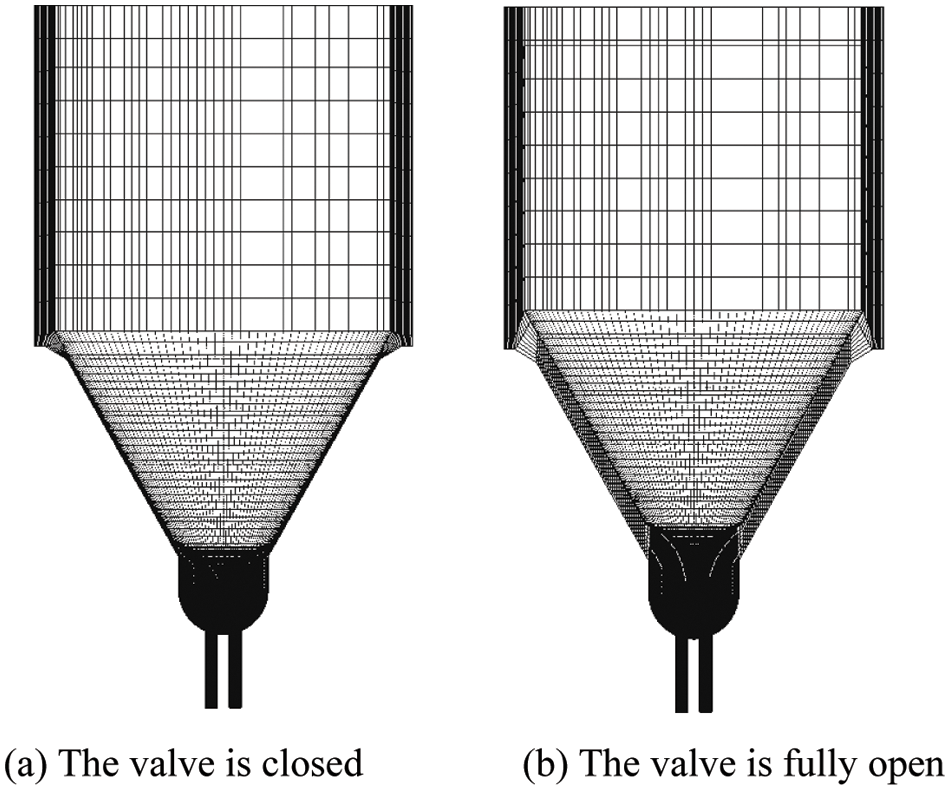
Figure 1: Schematic of computational domain and grid for diesel group-hole nozzle

The inlet and outlet boundary conditions were specified as pressure boundary. Meanwhile, the intermediate wall condition was set as the axisymmetric boundary, and the other wall boundary conditions were set to non-slip wall boundary. According to experiment, nozzle hole inlet and outlet pressure were set at 40 and 0.1 MPa, respectively. Moreover, flow characteristic parameter for each step of the nozzle hole outlet was saved and used as the inlet boundary conditions for the subsequent numerical simulation.
According to the experiment, the calculation region of spray can be simplified to a cylinder with a length of 30 cm and a diameter of 10 cm, as shown in Fig. 2. The nozzle is located at the center of the cylinder top. In the study, grids with sizes 0.8, 0.5, and 0.3 mm were selected to do the grid independence verification. Since spray droplets are mainly distributed on the axis of the cylinder, mesh refinement was applied to the square area of the grid center 10 * 10 mm. Therefore, three different grid numbers of 60000, 144000 and 200000 were used to verify grid independence. The spray penetration length of the three different grids were obtained from the numerical results.
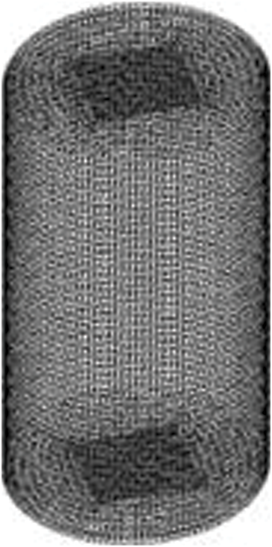
Figure 2: Computational grid of the constant volume bomb
Fig. 3 shows the numerical simulation results of penetration lengths under three different grids. The calculation results of the penetration length are almost the same for three different computational grids, which indicates a rather good independency of the grids. In order to balance calculation accuracy and time cost, a total of 144000 grids were selected for numerical calculation.
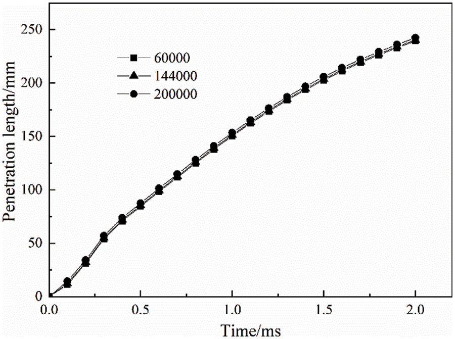
Figure 3: Grid independence study for penetration length under different grids
Simulation of internal flow of nozzle hole employed the two-fluid model, which is formulated by considering each phase separately. Two-fluid model is expressed in terms of two sets of conservation equations governing the balance of mass, momentum, and energy in each phase [35]. In the phase transition between the gas and liquid, the temperature of the diesel is constant by ignoring the heat absorbed and consumed. Since the flow rate of diesel in the nozzle is relatively high, which can reach several hundred meters per second, and the fuel stays in the nozzle hole for a short time, it can be considered that the heat exchange between fuel and the inner wall of the nozzle hole is almost zero [36]. The finite volume method was employed to discretize the governing equations and the pressure correction was based on the PISO algorithm. As the nozzle hole flow is the relatively complex, mainly turbulence, in order to accurately calculate the flow field characteristics in the nozzle hole, it is necessary to select an appropriate turbulence model. Moreover, since diesel fuel is incompressible, the standard two-equation k-ε turbulence model was adopted to calculate the liquid and gas phases.
The spray model has a great influence on the results of numerical simulation. Therefore, two stages of primary atomization and secondary atomization were considered comprehensively in the spray simulation. The primary atomization plays an important role in the coupling simulation method, which establishes the connection between internal cavitating flow and subsequent spray. The core injection model was chosen as the primary atomization model in this paper, which has a good prediction of primary atomization. The model assumes that the turbulence at the exit of the nozzle was the main reason for the surface fluctuation of the jet, which could enhance the formation of atomized droplets. Due to the high injection velocity, secondary atomization occurs near the injector and the selection of an appropriate breakup model would significantly affect the prediction of the spray evolution. KH-RT breakup model was selected for the secondary atomization because of its superior performance in predicting the spray structure [37].
The experimental equipment used in this paper mainly includes high pressure common rail diesel injection system, optical system and image acquisition system, as shown in Fig. 4. The high injection pressure of the common rail system was provided by the fuel pump. The pressure sensor was used to determine the static pressure value in the fuel rail, which could bring about real-time control of the injection pressure and minimize the influence of pressure fluctuation on fuel atomization. The measurement error of the pressure sensor is 0.5%. Images of the spray were obtained using a time resolution of 16 μs of a highspeed digital camera (Motion Pro-10000) produced by American REDLAKE MASD with a spatial resolution of 512 * 512 pixels. A Nikon AF Micro 60 mm f/2.8D macro lens with a magnification of 1 and a filter size of 62 mm was used. A LED light was used as the light source, which is composed of 99 small LED lamps with 100 W illumination brightness. It can well meet the light source requirements of the experiment. The diameter of single-hole and group-hole nozzle used in the experiment were 0.17 and 0.12 mm, respectively, and their cross-sectional areas were kept constant to ensure that they have the same flow rate. The spray experiment was carried out at room temperature of 25°C and standard atmospheric pressure. The injection pressures were 40 and 60 MPa. The spray atomization image was obtained in the atmospheric back-pressure, therefore the penetration distance was longer. The difference of light and dark level can reflect the density and uniformity of droplet distribution [38]. The spray processes of the group-hole and single-hole nozzle under different injection pressures were experimented using backlight method, the spray shape was observed, and the penetration length was measured.
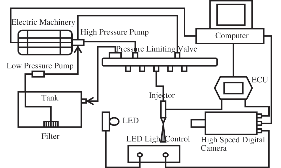
Figure 4: Schematic of experimental setup
The accuracy of the numerical models is validated by contrasting the penetration length of numerical result with experimental results under the same injection pressure. Fig. 5 shows the numerically calculated and experimental penetration length from 0.1 to 2 ms under the injection pressure of 40 and 60 MPa. It can be observed from Fig. 5 that the profiles of simulation are basically consistent with the points measured from the experiment, which demonstrates that the simulation results showed approximately good agreement with the experimental results. This indicates a good accuracy of the numerical model adopted in this study.
Figure 5: Model validation for spray penetration length of experimental and numerical results
3.1 Effect of Intake Conditions on Spray Characteristics
The spray characteristics of single-hole nozzle and group-hole nozzle were studied under different inlet conditions. The geometry of the single-hole and the group-hole nozzle used in this study remained the same to ensure consistent flow rates. The intake conditions included temperature and pressure in the constant volume chamber, and their values are shown in Table 2.

3.1.1 Effect of Fuel Temperature
Fig. 6 shows spray characteristics of single-hole nozzle and group-hole nozzle under different fuel temperature. It can be seen from Fig. 6a that the penetration length of the group-hole and single-hole nozzle were very close, but the penetration length of single-hole nozzle was a bit longer than that of the group-hole nozzle. The penetration length of both the group-hole and single-hole nozzles decreased slightly as the diesel temperature increased. The results obtained from the current numerical simulation are similar as those of Park, who used the Bosch tube method in an experiment to obtain the injection pattern of the group-hole and single-hole nozzles and found that under the same intake conditions, the injection pattern of group-hole nozzle is similar to that of the single-hole nozzle [39]. As shown in Figs. 6b and 6c, in the first 2 ms of the spray process, with increase in fuel temperature, the diesel evaporation mass increased and the SMD value gradually decreased. This is because as the temperature of the fuel increases, the evaporation rate of the fuel increases, resulting in a smaller diameter of the fuel droplets. Compared to single-hole nozzle, group-hole nozzle has smaller SMD value and larger evaporation mass. This indicates that the group-hole nozzle has more advantages than the single-hole nozzle in spray characteristics, which can make fuel and gas mix faster, thus improving the fuel atomization performance.
Figure 6: Spray characteristics under different fuel temperature
Fig. 7 shows spray characteristics of single-hole nozzle and group-hole nozzle under different initial pressure. As shown in Fig. 7a, when the pressure in the constant volume bomb was raised from 0.1 to 1 MPa, the air density became larger, and the air resistance of the spray droplets increased during the movement, resulting in a shorter spray penetration. Compared to the results of changing fuel temperature, spray characteristics are more sensitive to the environmental pressure changes. The penetration length of the single-hole nozzle is larger than that of the group-hole nozzle, but the trend is the same for both with pressure changes. As it can be seen in Fig. 7b, the evaporation mass of the two nozzles decreased with increase in the pressure in the constant volume bomb, and the variation trend of evaporation mass was consistent with the time. The evaporation mass increased rapidly with time under the pressure of 0.1 MPa, while the growth rate decreased gradually with pressure. However, no matter what the pressure was, the evaporation mass of group-hole nozzle is always slightly higher than that of single-hole nozzle, and the difference between them was more obvious after the disappearance of cavitation (t > 0.8 ms). Fig. 7c shows that when t < 0.76 ms, SMD value decreased with time continuously, while when t > 0.76 ms, SMD value basically remained unchanged. It can also be concluded that the penetration length decreases with the increase in pressure. This is because as the pressure increases, the mass of the droplet decreases and the propagation kinetic energy of the droplet decreases accordingly, thus reducing the penetration length. Similarly, the SMD value of droplets injected by group-hole nozzle is smaller than that of single-hole nozzle, therefore the penetration length is also slightly smaller than that of single-hole nozzle.
Figure 7: Spray characteristics under different initial pressure
3.2 Effect of Nozzle Geometry on the Flow and Spray Characteristics
Numerical simulations were also carried out to investigate the flow and spray characteristics of the group-hole nozzle under different nozzle geometry. The spray characteristics of single-hole nozzle and group-hole nozzle under different nozzle geometry were also compared. The nozzle geometry includes hole length (L) and orifice entrance curvature radius (R), and their values are shown in Table 3.

3.2.1 Effect of Nozzle Length on the Flow and Spray Characteristics
Fig. 8 shows the internal flow of the group-hole nozzle with different hole length. As shown in Fig. 8a, with the hole length increasing from 0.55 to 0.75 mm, the pressure distribution inside the nozzle hole remained the same. However, as shown in Figs. 8a and 8b, as the length of the nozzle became longer, the flow resistance also increased, which led to a decrease in the flow velocity of the liquid phase, an increase in the turbulent kinetic energy dissipation time and a decrease in the turbulent kinetic energy. Fig. 9 shows average velocity and kinetic turbulent energy in the group-hole nozzle with different hole length. The average velocity and kinetic turbulence energy in the nozzle hole showed a decreasing trend with increase in the hole length. This is because with increase in hole length, the resistance of fuel flow through the nozzle hole increases significantly, resulting in a decrease in the average flow velocity. At the same time, the average turbulent kinetic energy also showed a decreasing trend. This is not only due to the factor of decreasing average velocity, but also due to the weakening of the cavitation in the nozzle hole, which makes the breakage of cavitation bubbles disappear, resulting in the weakening of turbulent flow.
Figure 8: Internal flow of the group-hole nozzle with different hole length
Figure 9: Average velocity and kinetic turbulent energy in the group-hole nozzle with different hole length
Fig. 10 shows the cavitation distribution of different nozzle length. It can be seen from the figure that increasing the hole length did not cause a dramatic change in the volume fraction of the gas phase, and the cavitation area remained almost the same. However, for the nozzle hole with short length, such as 0.55 mm, the cavitation area accounted for a large proportion of the space, and there was a tendency of super cavitation. While the nozzle hole with long length, such as 0.75 mm, did not show this tendency. Therefore, the nozzle length had little effect on cavitation, but only that the droplet in the long nozzle hole had broken and disappeared before reaching the nozzle outlet, while in the short nozzle hole, the droplet breaking effect was more obvious.
Figure 10: Cavitation distribution of different nozzle length
According to Hiroyasu et al. [9], a complete injection process generally consists of two stages. The first stage is the primary breakup from the beginning of spraying to the breaking moment of droplets. In this stage, the penetration length of spray increases linearly with time. After tbreak, large droplets break up into smaller droplets, and new cavitation bubbles grow during secondary breakup. The secondary breakup plays a significant role in increasing the total fuel and liquid surface to bolster the combustion and fuel evaporation. The break up time in this study was calculated from Eq. (1) as tbreak = 0.76 ms.
where ∆P is the difference between injection pressure and ambient pressure; ρg is the density of gas in the constant volume bomb; ρl is density of fuel; D is the nozzle diameter.
Fig. 11 compares the SMD value of the group-hole nozzle and single-hole nozzle with different nozzle lengths at t = tbreak = 0.76 ms. It can be seen that the SMD value of either group-hole nozzle or single-hole nozzle decreased slightly with increase in nozzle length. Combined with the analysis results of the internal flow, it can be seen that this was due to increase in the nozzle length, the internal cavitation phenomenon was weakened and the droplet breaking was weakened, resulting in a larger SMD value. It can also be seen from the figure that the increase in the nozzle length changed the location of cavitation in the nozzle hole. When the length of the group-hole increases to 0.75 mm, the cavitation time was advanced, which made the cavitation phenomenon occur when R/D = 0.12, resulting in no change in the SMD value. At the same time, when the nozzle length of the single-hole nozzle was 0.75 mm and R/D = 0.12, the SMD value changed significantly, which was different from that of other nozzle lengths. This was also caused by the early occurrence of the cavitation phenomenon due to the movement of the cavitation position. The SMD of the group-hole nozzle was smaller than the SMD of the corresponding single-hole nozzle at different R/D, which indicates that the group-hole nozzle has better spray characteristics and is more advantageous for evaporative combustion than the single-hole nozzle.
Figure 11: Effects of nozzle length on SMD
Fig. 12 shows the variation of spray penetration length with R/D for the group-hole nozzle and single-hole nozzle at different nozzle lengths at t = tbreak = 0.76 ms. Due to the droplet collision during spray process of the group-hole nozzle, the kinetic energy was reduced, therefore the penetration length was slightly less than that of the single spray hole with equal cross-section. However, the effect of nozzle length on the penetration distance of single-hole nozzle and group-hole nozzle was similar. It can be seen from the results of internal flow field characteristics that the change in length-diameter (L/D) ratio can inhibit the occurrence of cavitation, which determines the injection velocity and the penetration length. With decrease in the nozzle length, the cavitation occurred more intensely, the flow velocity at the outlet of the nozzle increased, and the penetration distance increased.
Figure 12: Effects of nozzle length on spray penetration length
Fig. 13 presents the variation of evaporation mass with R/D for the group-hole nozzle and single-hole nozzle at different nozzle lengths at t = tbreak = 0.76 ms. When R/D < 0.12, the evaporation mass of group-hole nozzle was greater than that of single-hole nozzle. The droplets sprayed from group-hole nozzle were more widely distributed in the radial direction due to its special structure, and the atomized droplets could contact the air as much as possible, which was conducive to the evaporation of fuel. Therefore, the fuel evaporation mass of the group-hole nozzle is greater than that of single-hole nozzle. As can be seen from the previous discussion, increasing the nozzle length would inhibit the cavitation flow, resulting in an increase in the SMD value of the droplet and a slight decrease in the evaporation mass. For the nozzle with L = 0.75 mm, cavitation would occur in advance when R/D > 0.12, and the evaporation mass of fuel would remain unchanged.
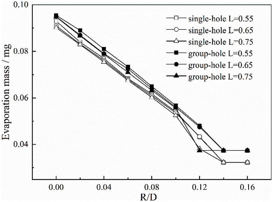
Figure 13: Effects of nozzle length on evaporation mass
3.2.2 Effect of Orifice Entrance Curvature Radius on the Flow and Spray Characteristics
Fig. 14 shows the internal flow of the group-hole nozzle with different orifice entrance curvature radius. With the orifice entrance curvature radius increasing from 0 to 0.025 mm, the pressure distribution inside the nozzle hole remaining the same, and increase in orifice entrance curvature radius, the flow resistance at the nozzle entrance decreased, allowing the fuel to transition from the nozzle body to the nozzle hole more smoothly, and the velocity direction of the fuel flowing from the nozzle pressure chamber to the nozzle hole did not show a large angle of rotation. The distribution of velocity and turbulent kinetic energy was also smoother and more uniform, and the maximum range of velocity and turbulent kinetic energy was reduced. Therefore, in order to improve the injection rate and the flow coefficient of the nozzle, many injection nozzles are designed to be rounded at the inlet part of the injection hole.
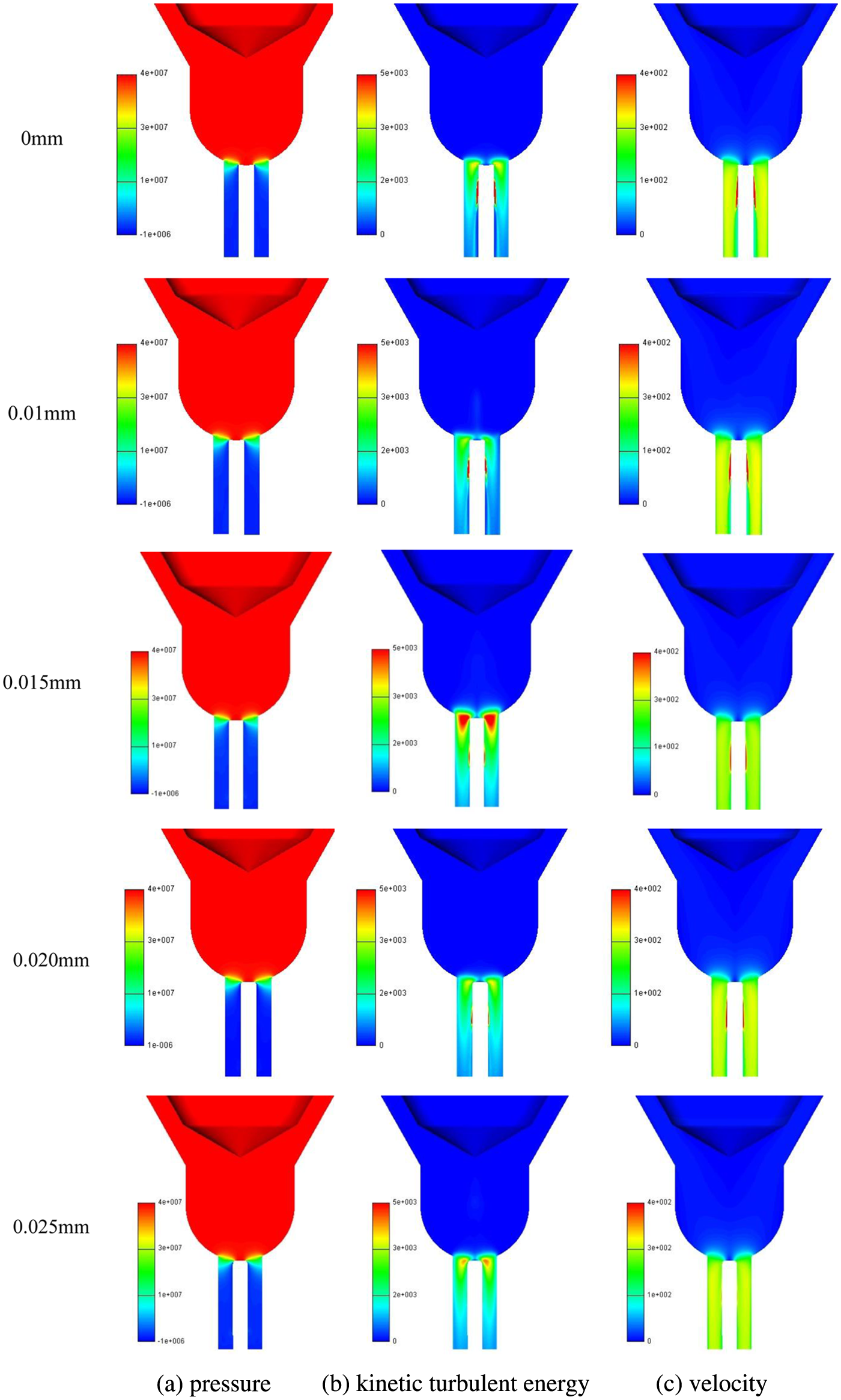
Figure 14: Internal flow of the group-hole nozzle with different orifice entrance curvature radius
Fig. 15 shows the average velocity and kinetic turbulent energy in the group-hole nozzle with different orifice entrance curvature radius. With increase in orifice entrance curvature radius, the average velocity at the outlet of the nozzle hole increased, and the kinetic turbulent energy decreased. The entrance curvature at the inlet of nozzle hole reduced the flow resistance, which made the flow of fuel into the injection hole go smoothly and suppressed the formation of cavitation. As the orifice entrance curvature radius continued to increase, the kinetic turbulent energy increased because the pressure in the downstream of the nozzle hole rose rapidly, which accelerated the bubble breaking process in the nozzle hole and promoted the turbulent flow of fuel.
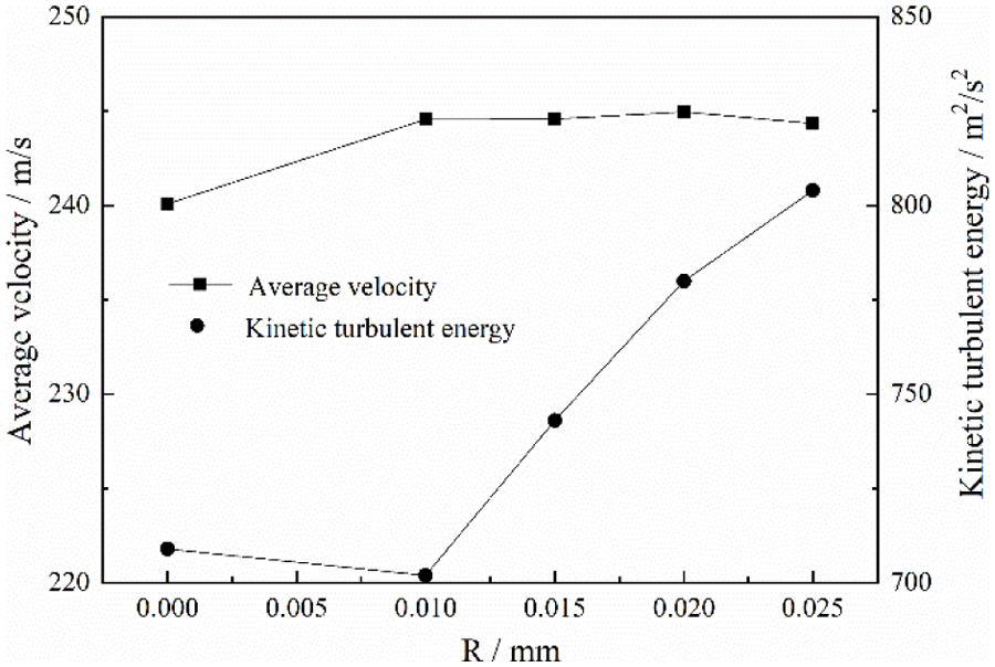
Figure 15: Average velocity and kinetic turbulent energy at the outlet of group-hole nozzle with different orifice entrance curvature radius
Fig. 16 shows cavitation distribution of different orifice entrance curvature radius. With increase in the orifice entrance curvature radius, the volume fraction of the gas phase decreased, which indicated that cavitation had been suppressed and fuel mass flow increased. Besides, the pressure at the outlet of the nozzle also rose rapidly, making the bubbles break quickly, the degree of cavitation was gradually weakened, and the length of cavitation was gradually reduced. The cavitation disappeared at the outlet of the nozzle hole with the orifice entrance curvature radius of 0.025 mm.
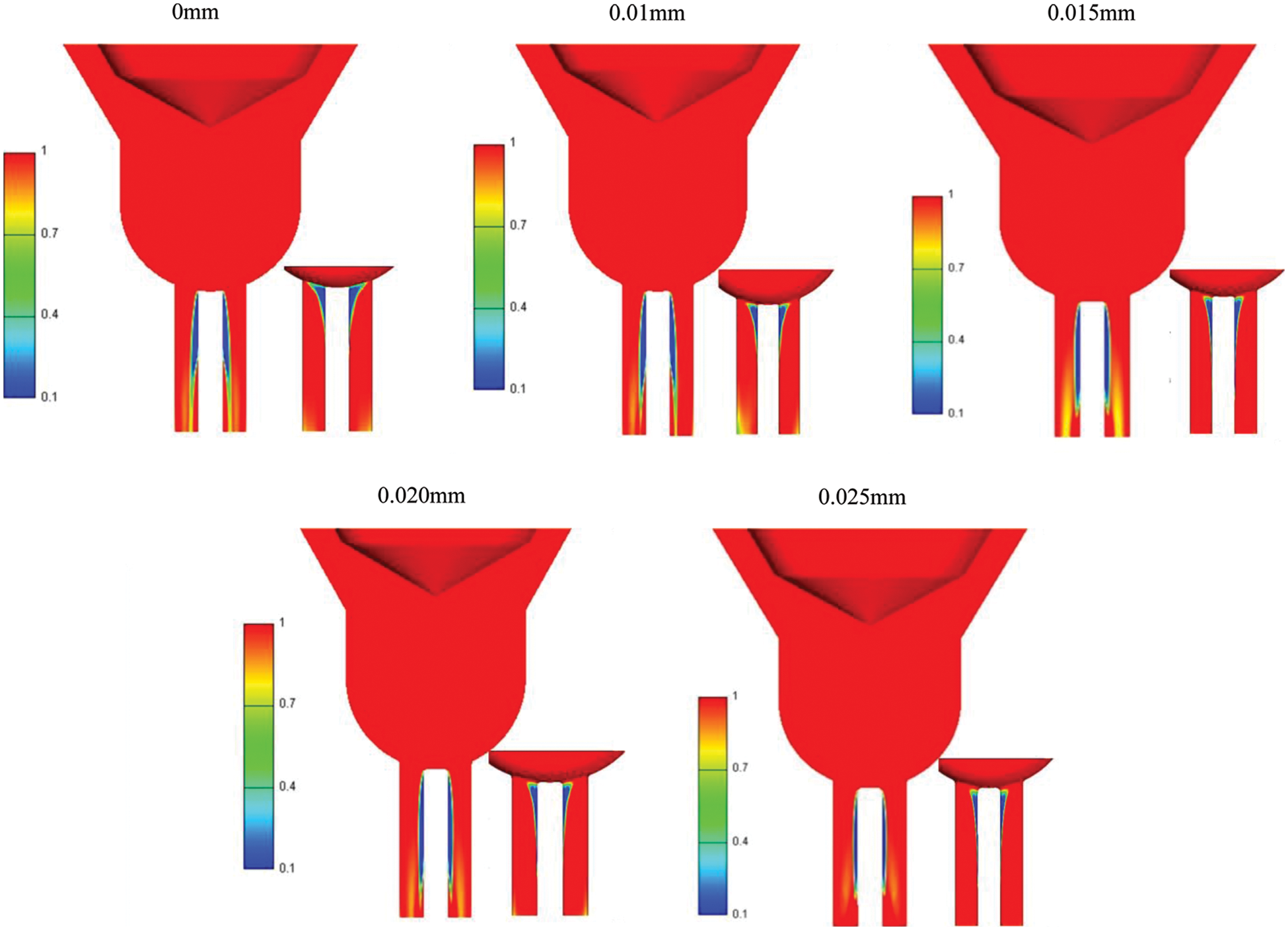
Figure 16: Cavitation distribution of different orifice entrance curvature radius
The effects of changing radius of orifice entrance curvature radius (R) on spray characteristics, such as SMD value, spray penetration length and evaporation mass, are shown in Figs. 17–19, respectively. The nozzle length was 0.75 mm, and the R/D (orifice entrance curvature radius/nozzle hole diameter, D = 0.75 mm) value increased from 0 to 0.16. Fig. 17 shows that with increase in R/D, the cavitation effect gradually disappeared, the number of bubbles formed by cavitation decreased, and the volume fraction of gas phase decreased, resulting in increase in SMD and decrease in atomization effect. It can also be seen from the figure that the curves of R/D = 0.12, 0.14 and 0.16 almost coincided, and the SMD value no longer changes, indicating that the cavitation effect had disappeared.

Figure 17: Effects of R/D on SMD
Figure 18: Effects of R/D on penetration length
Figure 19: Effects of R/D on evaporation mass
As shown in Fig. 18, when R/D = 0, the inlet of the nozzle hole was sharp, according to previous analysis of the internal flow field, the cavitation phenomenon was much more obvious than that of the rounded inlet in this case, the gas phase volume fraction in the injection hole was large. The effective flow cross-sectional area of the fuel in the injection hole was narrow, the flow resistance increased, and the velocity of fuel flowing out of the nozzle was low. With increase in orifice entrance curvature radius, the turbulent kinetic energy at the nozzle entrance increases and the influence of cavitation was weakened, therefore the penetration length became longer. Similar to the trend of SMD, when R/D > 0.12, the curves almost coincided, indicating that the cavitation phenomenon disappeared at these cases and the penetration length reached its maximum and no longer changed with change in the orifice entrance curvature radius.
Fig. 19 shows the variation in evaporation mass for different R/D during the 2 ms injection period. At the beginning of the spray, there was little difference in evaporation mass. The fuel evaporation was low because the SMD value was high. As the spray proceeds, the cavitation bubbles had the secondary breakup, resulting in smaller SMD and higher spray evaporation, therefore allowing better mixing of the fuel mist and air. The existence of fuel vapor bubbles allowed more air into the spray, and then the fuel evaporation mass changed. With continuous increase in R/D, the droplet diameter increased, the surface area of the droplet in contact with the air medium correspondingly increased, the droplet heat dissipation increased, the surface temperature decreases, and the evaporation quality decreased. When R/D > 0.12, the cavitation phenomenon completely disappeared, therefore the evaporation mass of fuel atomization would not change.
In this study, a nozzle spray model coupled with internal cavitating flow model based on CFD software AVL FIRE was established to study the flow and spray characteristics of group-hole nozzle. The effects of intake conditions (injection pressure and temperature) and nozzle geometry parameters (orifice entrance curvature radius and nozzle length) on spray characteristics were numerically investigated. The differences in Sauter mean diameter (SMD), penetration length and fuel evaporation mass between single-hole nozzle and group-hole nozzle under different nozzle geometry were discussed. The major conclusions are as follows:
1) With increase in fuel temperature, the evaporation mass of the group-hole nozzle increases, the penetration length and the SMD value decreases. However, all of them decrease with increase in ambient pressure. Under the same intake conditions, the atomization effect of group-hole nozzle is better than single-hole nozzle.
2) The geometry of the nozzle has an important effect on cavitation flow and subsequent spray characteristics. With increase in nozzle length, cavitation effect is weakened, resulting in the reduction of droplet fragmentation, increase in SMD value, and decrease in evaporation mass. Therefore, the atomization effect of short nozzle is better than that of long nozzle.
3) With increase in the orifice entrance curvature radius, the average velocity and turbulent kinetic energy of the liquid phase increase, which is conducive to improving the injection rate and flow coefficient of the nozzle. Meanwhile, the penetration length and SMD value rise, while evaporation mass drops. When the ratio of the orifice entrance curvature radius (R) to diameter of injection hole (D) equals to 0.12, the spray characteristics reach a constant state due to the elimination of cavitation.
Funding Statement: This work was supported by the National Natural Science Foundation of China (Grant No. 52276117) and Qing Lan Project.
Conflicts of Interest: The authors declare that they have no conflicts of interest to report regarding the present study.
References
1. Behcet, R., Aydın, H., İlkılıç, C., İşcan, B., Aydın, S. (2014). Diesel engine applications for evaluation of performance and emission behavior of biodiesel from different oil stocks. Environmental Progress & Sustainable Energy, 34(3), 890–896. https://doi.org/10.1002/ep.12045 [Google Scholar] [CrossRef]
2. Karabaş, H., Boran, S. (2018). Comparison of engine performance and exhaust emission properties of diesel and safflower biodiesel using multi-response surface methodology. Environmental Progress & Sustainable Energy, 38(4), e13034. https://doi.org/10.1002/ep.13034 [Google Scholar] [CrossRef]
3. Gumus, M., Sayin, C., Canakci, M. (2012). The impact of fuel injection pressure on the exhaust emissions of a direct injection diesel engine fueled with biodiesel-diesel fuel blends. Fuel, 95, 86–494. https://doi.org/10.1016/j.fuel.2011.11.020 [Google Scholar] [CrossRef]
4. He, L., Ruiz, F. (1995). Effect of cavitation on flow and turbulence in plain orifices for high-speed atomization. Atomization and Sprays, 5(6), 569–584. https://doi.org/10.1615/AtomizSpr.v5.i6.30 [Google Scholar] [CrossRef]
5. Kushari, A. (2010). Effect of injector geometry on the performance of an internally mixed liquid atomizer. Fuel Processing Technology, 9(11), 1650–1654. https://doi.org/10.1016/j.fuproc.2010.06.014 [Google Scholar] [CrossRef]
6. Soteriou, C., Andrews, R., Smith, M. (1995). Direct injection diesel sprays and the effect of cavitation and hydraulic flip on atomization. SAE International Journal of Engines, 104, 128–153. [Google Scholar]
7. Ganippa, L. C., Bark, G., Andersson, S., Chomiak, J. (2004). Cavitation: A contributory factor in the transition from symmetric to asymmetric jets in crossflow nozzles. Experiments in Fluids, 36(4), 627–634. https://doi.org/10.1007/s00348-003-0736-4 [Google Scholar] [CrossRef]
8. Bergwerk, W. (1959). Flow pattern in diesel nozzle spray holes. Proceedings of the Institution of Mechanical Engineers, 173(1), 655–660. https://doi.org/10.1243/PIME_PROC_1959_173_054_02 [Google Scholar] [CrossRef]
9. Hiroyasu, H., Arai, M. (1990). Structures of fuel sprays in diesel engines. SAE International Journal of Engine, 99, 1050–1061. https://doi.org/10.4271/900475 [Google Scholar] [CrossRef]
10. Soteriou, C., Andrews, R., Smith, M. (1999). Further studies of cavitation and atomization in diesel injection. SAE International Journal of Engine, 108, 902–919. [Google Scholar]
11. He, Z., Zhong, W., Wang, Q., Jiang, Z., Shao, Z. (2013). Effect of nozzle geometrical and dynamic factors on cavitating and turbulent flow in a diesel multi-hole injector nozzle. International Journal of Thermal Sciences, 70(8), 132–143. https://doi.org/10.1016/j.ijthermalsci.2013.03.008 [Google Scholar] [CrossRef]
12. Schmidt, D. P., Rutland, C. J., Corradini, M. L. (1999). A fully compressible, two-dimensional model of small, high-speed, cavitating nozzles. Atomization and Sprays, 9(3), 255–276. https://doi.org/10.1615/AtomizSpr.v9.i3.20 [Google Scholar] [CrossRef]
13. Kim, J. H., Nishida, K., Hiroyasu, H. (1997). Characteristics of the internal flow in a diesel injection nozzle. International Journal of Fluid Mechanics Research, 24(1–3), 34–44. https://doi.org/10.1615/InterJFluidMechRes.v24.i1-3.40 [Google Scholar] [CrossRef]
14. Nurick, W. H. (1976). Orifice cavitation and its effect on spray mixing. Journal of Fluids Engineering, 98(4), 681–687. https://doi.org/10.1115/1.3448452 [Google Scholar] [CrossRef]
15. He, L., Ruiz, F. (1995). Effect of cavitation on flow and turbulence in plain orifices for high-speed atomization. Atomization and Sprays, 5(6), 569–584. https://doi.org/10.1615/AtomizSpr.v5.i6.30 [Google Scholar] [CrossRef]
16. Plesset, M. S. (1949). The dnamics of cavitation bubbles. Journal of Applied Mechanics, 16(3), 277–282. https://doi.org/10.1115/1.4009975 [Google Scholar] [CrossRef]
17. Rayleigh, L. (1917). On the pressure developed in a liquid during the collapse of a spherical. The London, Edinburgh, and Dublin Philosophical Magazine and Journal of Science, 34(200), 94–98. https://doi.org/10.1080/14786440808635681 [Google Scholar] [CrossRef]
18. Yuan, W. X., Sauer, J., Schnerr, G. H. (2001). Modeling and computation of unsteady cavitation flows in injection nozzles. Mécanique & Industries, 2(5), 383–394. https://doi.org/10.1016/S1296-2139(01)01120-4 [Google Scholar] [CrossRef]
19. Alajbegovic, A., Grogger, H. A., Philipp, H. (1999). Calculation of the transient cavitation in nozzle using the two-fluid model. Proceedings of the 12th Annual Conference on Liquid Atomization and Spray Systems, pp. 373–377. Indianapolis, USA. [Google Scholar]
20. Ogsawara, M., Sami, H. (1967). A study on the behavior of a fuel droplet injected into the combustion chamber of a diesel engine. SAE International Journal of Engine, 76, 1690–1707. https://doi.org/10.4271/670468 [Google Scholar] [CrossRef]
21. Dent, J. C. (1971). A basis for the comparison of various experimental methods for studying spray penetration. SAE Transactions, 80, 1881–1884. https://doi.org/10.4271/710571 [Google Scholar] [CrossRef]
22. Espey, C., Dec, J. E. (1995). The effect of TDC temperature and density on the liquid-phase fuel penetration in a D. I. diesel engine. SAE Transactions, 104, 1400–1416. https://doi.org/10.4271/952456 [Google Scholar] [CrossRef]
23. Vita, A. D., Allocca, L. (2003). Experimental analysis and CFD simulation of GDI sprays. SAE 2003 World Congress & Exhibition, 64, 3684–3694. https://doi.org/10.4271/2003-01-00042003 [Google Scholar] [CrossRef]
24. Mitroglou, N., Nouri, J. M., Gavaises, M., Arcoumanis, C. (2006). Spray characteristics of a multi-hole injector for direct-injection gasoline engines. International Journal of Engine Research, 7(3), 255–270. https://doi.org/10.1243/146808705X62922 [Google Scholar] [CrossRef]
25. Arcoumanis, C., Gavaises, M., French, B. (1997). Effect of fuel injection processes on the structure of diesel sprays. SAE Transactions, 106, 1025–1064. https://doi.org/10.4271/970799 [Google Scholar] [CrossRef]
26. Bianchi, G. M., Pelloni, P. (1999). Modeling the diesel fuel spray breakup by using a hybrid model. SAE Technical Paper 1999-01-0226. https://doi.org/10.4271/1999-01-0226 [Google Scholar] [CrossRef]
27. Yong, L., Ruiqin, H. (2013). Micro electrochemical machining for tapered holes of fuel jet nozzles. Procedia CIRP, 6, 395–400. https://doi.org/10.1016/j.procir.2013.03.085 [Google Scholar] [CrossRef]
28. Nishida, K., Nomura, S., Zhang, Y., Ito, T. (2003). Spray characteristics of group-hole nozzle for D. I. diesel engine. SAE Technical Paper 2003-01-3115. https://doi.org/10.4271/2003-01-3115 [Google Scholar] [CrossRef]
29. Hajialimohammadi, A., Honnery, D., Abdullah, A., Mirsalim, M. A. (2013). Time resolved characteristics of gaseous jet injected by a group-hole nozzle. Fuel, 113, 497–505. https://doi.org/10.1016/j.fuel.2013.05.050 [Google Scholar] [CrossRef]
30. Jian, G., Moon, S., Zhang, Y., Nishida, K., Matsumoto, Y. (2009). Flame structure of wall-impinging diesel fuel sprays injected by group-hole nozzles. Combustion and Flame, 156(6), 1263–1277. https://doi.org/10.1016/j.combustflame.2009.01.014 [Google Scholar] [CrossRef]
31. Park, S. W., Reitz, R. D. (2009). Optimization of fuel/air mixture formation for stoichiometric diesel combustion using a 2-spray-angle group-hole nozzle. Fuel, 88(5), 843–852. https://doi.org/10.1016/j.fuel.2008.10.028 [Google Scholar] [CrossRef]
32. Park, S. W., Reitz, R. D., Kim, J. (2011). Combustion and emission characteristics of converging group-hole nozzle under lean engine operating conditions. Fuel, 90(11), 3259–3267. https://doi.org/10.1016/j.fuel.2011.06.021 [Google Scholar] [CrossRef]
33. Moon, S., Matsumoto, Y., Nishida, K., Jian, G. (2010). Gas entrainment characteristics of diesel spray injected by a group-hole nozzle. Fuel, 89(11), 3287–3299. https://doi.org/10.1016/j.fuel.2010.05.011 [Google Scholar] [CrossRef]
34. Lee, S., Park, S. (2014). Spray atomization characteristics of a GDI injector equipped with a group-hole nozzle. Fuel, 137(9), 50–59. https://doi.org/10.1016/j.fuel.2014.07.063 [Google Scholar] [CrossRef]
35. Ishii, M., Hibiki, T. (2010). Thermo-fluid dynamics of two-phase flow. 2nd edition, pp. 98–99. New York: Springer. https://doi.org/10.1007/978-1-4419-7985-8 [Google Scholar] [CrossRef]
36. Payri, R., García, J. M., Salvador, F. J., Gimeno, J. (2005). Using spray momentum flux measurements to understand the influence of diesel nozzle geometry on spray characteristics. Fuel, 84(5), 551–561. https://doi.org/10.1016/j.fuel.2004.10.009 [Google Scholar] [CrossRef]
37. Patterson, M. A., Reitz, R. D. (1998). Modeling the effects of fuel spray characteristics on diesel engine combustion and emission. SAE Transactions, 27–43. https://doi.org/10.4271/980131 [Google Scholar] [CrossRef]
38. Kadamb, J. R., Martin, W. T., Amirthaganesh, S. (1998). Particle sizing using particle imaging velocimetry for two-phase flows. Powder Technology, 100(2–3), 251–259. https://doi.org/10.1016/S0032-5910(98)00146-6 [Google Scholar] [CrossRef]
39. Park, S. W., Reitz, R. D. (2009). A gas jet superposition model for CFD modeling of group-hole nozzle sprays. International Journal of Heat and Fluid Flow, 30(6), 1193–1201. https://doi.org/10.1016/j.ijheatfluidflow.2009.06.002 [Google Scholar] [CrossRef]
Cite This Article
 Copyright © 2023 The Author(s). Published by Tech Science Press.
This work is licensed under a Creative Commons Attribution 4.0 International License , which permits unrestricted use, distribution, and reproduction in any medium, provided the original work is properly cited.
 Downloads
 Citation Tools