
 Submit a Paper
 Propose a Special lssue
 Open Access
ARTICLE

Waste Heat Recovery from a Drier Receiver of an A/C Unit Using Thermoelectric Generators
1 Energy Engineering Department, Faculty of Engineering/AL-Mussayib, University of Babylon, Hilla, Babylon, Iraq
2 Construction and Projects Department, Al Iraqia University, Baghdad, Iraq
3 Department of Electrical Engineering, University of Technology, Baghdad, Iraq
* Corresponding Author: Ali Jaber Abdulhamed. Email:
Energy Engineering 2023, 120(8), 1729-1746. https://doi.org/10.32604/ee.2023.029069
Received 30 January 2023; Accepted 12 April 2023; Issue published 05 June 2023
 View Full Text
 Download PDF
Abstract
Thermoelectric generators (TEGs) are considered promising devices for waste heat recovery from various systems. The Seebeck effect can be utilized to generate power using the residual heat emitted by the filter dryer receiver (FDR) of an air conditioning (A/C) system, which would otherwise go to waste. The study aims to build a set of thermoelectric generators (TEG) to collect the waste heat of the FDR and generate low-power electricity. A novel electrical circuit with two transformers is designed and fabricated to produce a more stable voltage for operation and charging. The thermoelectric generator (TEGs) was installed on the FDR of the A/C unit. The test showed that climate conditions have a significant impact on the output power generated from the system. The results showed that the peak voltage recorded in the current study is 5.2 V per day (wet, cold, and wind weather) with an output power of 0.2 W. These values are acceptable for powering the load and charging a single battery with 3.5 V as the voltage increases battery 0.1 V/20 min charge. A case study of operating the emergency signs in a building was considered. The current heat recovery system is deemed to be easily installed and can be connected to a network of TEGs to produce more power.Keywords
Nomenclature
| Figure of Merit | |
| dimensionless Figure of Merit | |
| Seebeck coefficient | |
| temperature | |
| cold side temperature of TEG | |
| hot side temperature of TEG | |
| heat sink surface temperature | |
| ambient temperature | |
| thermal conductivity | |
| thermal conductivity per meter (W/K) | |
| voltage (V) | |
| current (Amp) | |
| FDR heat transfer rate (W) | |
| electric power of TEG (W) | |
| heat loss (W) | |
| heat transfer through heat sink (W) | |
| external load resistance (ohm) | |
| internal resistance of the system (ohm) | |
| heat sink surface area | |
| heat transfer coefficient (W/m2/K) | |
| ac | alternative current |
| A/C | air-conditioning unit |
| OCV | open circuit voltage |
| CCV | closed circuit voltage |
| Greek Symbols | |
| electric conductivity | |
| power factor | |
| maximum efficiency | |
By 2030, there is an estimated increase of more than 60% in the global energy demand [1]. The future challenges involve the storage of energy generated and limited spare fossil fuel. Nowadays, pollution and carbon dioxide CO2 emissions are the significant wastes of use heat engines that produce 80% of the world’s energy demand [1]. One-third of the heat generated from burning fossil fuel in internal combustion engines (ICE) is rejected as waste heat to the environment [2]. The engine of a small vehicle loses between 500°C to 900°C of temperature to the surrounding, while large engines produce between 400°C to 650°C [3]. In the United States, the report of the Department of Energy showed that about 50% of all fuel combusted is emitted to the environment [4] as heat waste and emissions.
The increasing energy demand has led to looking for alternative energy sources. Therefore, solar, wind and geothermal energy were employed to produce energy as a replacement for fossil fuels. However, these energy sources are costly and address a minor range of the world’s energy requirements. Solar, wind and geothermal energy cover 2.7% of the United States’ requirement for energy [1]. Therefore, waste heat energy can be considered a significant energy source, described as inexpensive, clean, and fuel-free [5,6]. The generation of waste heat can be categorized into three groups depending on the degree of temperature produced, namely low, medium, and high-temperature ranges. The low range varies between the maximum temperature of 230°C generated by annealing furnaces and the minimum 32°C temperature generated by welding machines [4].
Thermoelectric generators (TEG) employ the Seebeck effect to transform heat into electrical power. Researchers utilized various sources that produced heat waste and integrated it with the TEG. Zhao et al. [7] installed the TEG on automobile exhaust with media fluid. The results showed that in comparison with the conventional TEG system, for a particular condition, the power generation is 3.39 times higher. Moreover, Massaguer et al. [8] assessed the fuel economy of an automobile by attaching several TEGs to the exhaust system. The work was performed experimentally and numerically using FEM and FVM. The comparison revealed that the fuel economy of the vehicle does not happen with the maximum power extracted from the waste heat. Furthermore, in a car, 40% of the fuel capacity is lost as heat through the exhaust gas [9]. Orr et al. [10] stated a modification employs a heat pipe and TEG system to replace the radiator of the car. The test result of a specific car showed that system produced 28 W power under a condition of the hot side being nearly 70°C and the cold side being 40°C. In another work Orr et al. [11] designed a system consisting of heat pipes and TEGs located on the exhaust of an automobile. According to the test results, the system generated the highest level of power that it could produce, of 38 W using the eight installed TEGs. Furthermore, the resulting efficiency of TEG was 2.46%. It was determined that the TEGs system installed on the vehicle’s exhaust performs better than the one installed on the radiator within the same module [12,13].
The temperature variation between both sides of the TEG is a crucial aspect, indeed, He et al. [14] studied the impact of the cooling method on the performance of the heat recovery system. The results showed that the water-cooling method needs a high module area to produce more power as compared to the method of air-cooling. The water-cooling system results showed the maximum power output increases with the mass flow rate and gas temperature. This is not the case for the air-cooling method. Two designs of heat exchangers were examined by Wang et al. [15]. The first one consisted of fins attached to the surface and another one, the surface was dimpled. The aim is to reduce the back pressure of the exhaust pipe. According to both the road test and the simulations, the use of a dimpled surface in the automotive thermoelectric generator (ATEG) resulted in a 20.57% decrease in pressure drop and a significant increase of 173.60% in net power output. Adding TEGs to the system apart from the heat recovery function also improves the performance of the main system. Sok et al. [16] demonstrated the effectiveness of TEGs in enhancing the performance of a hybridized 3.0 L CNG engine. The author concluded that the engine brake thermal efficiency is enhanced by 0.56% using a 7.0 × 9.0 TEG module arrangement. In another work [17], the author utilized the TEG heat recovery system to optimize the capabilities of a 2.2-litre diesel engine designed for upcoming electric powertrains. A 1.1% break thermal efficiency improvement was produced [17]. Akçay et al. [18] studied numerically a system that encompasses a thermoelectric generator (TEG) installed on an exhaust spark-ignition engine to transform the waste heat energy to electrical energy. The study focused on analyzing the effect of the fin arrangement and exchanger structure used in a TEG system. The findings showed that dividing the internal volume of the heat exchanger into two equal parts with a separating plate led to a 32.45% increase in temperature difference and the addition of flow guide vanes attached on the plate surface of the separator, resulted in an 18.79% increase.
In another aspect the TEGs can be installed on the rear face of the parabolic through collector; also, it can be fixed on the absorber tube where the temperature reaches more than 150°C. This combination can obtain 18 W of power [19]. Kraemer et al. [20] attached a system of TEG on the lower surface of a flat-panel absorber configuration. The author suggested another method of producing electricity from solar heat. The reported efficiency of the system is about 4.6%. Li et al. [21] proposed the development of a prototype solar thermoelectric generator that concentrates solar heat. The system consisted of a solar collector to gather the sun’s heat and directed it towards the heat collector in the middle. Inside the heat collector, the TEG was installed attached to the hot side and the cold plate from another side. The results show that the highest possible efficiency of the system was 14.1% [21]. The performance of a solar thermoelectric generator under real operating conditions was numerically analyzed to investigate how to input energy impacts its functionality by Xiao et al. [22]. Amatya et al. [23] showed that the design of a solar thermoelectric generator (STG) that utilizes parabolic concentrators is proposed as an economical option for generating small amounts of power, in place of solar photovoltaics with a system efficiency of 3.0%. Baranowski et al. [24] reported 15.9% overall efficiency of the system of TEGs heat from the sun irradiance.
The walls of buildings are an excellent heat source to operate TEG, where it receives heat from artificial lights, sunlight, and cooking devices [25]. However, human body activities can generate about (0.5 to 5.0) mW, which is enough to recharge a small battery [26], where the heat of human stress is considered a heat source. At the same time, the surrounding air is regarded as a cold source [26,27].
Many air-conditioning (A/C) units are utilized daily in state institutions, facilities and residential complexes in Malaysia, where the tropical climate involves hot and wet weather with 21°C to 32°C of ambient temperature [28,29]. In Malaysia, the ambient temperature increases by (5°C to 7°C) due to heat emissions from vehicle engines, furnaces, and A/C units. The Filter Drier Receiver (FDR) of A/C units generates a substantial amount of lost heat in the surroundings due to the high demand for household refrigerator-freezers in Malaysia [30]. Moreover, from the previous studies, the FDR was not considered to generate electrical power from its heat waste. Therefore, the current study introduces an experimental test for a system consisting of a TEG circuit to generate electricity by recovering heat from an A/C unite drier and a suggestion of a novel electrical circuit to charge a battery with high power efficiency. Also, a study of the climate change effect on system operation is performed.
2.1 Thermoelectric Power Generator (TEG)
Thermoelectric power generator (TEG) consists of two types of semiconductor material, such as Bismuth Telluride (Bi2Te3), that directly transfers heat energy into electric energy [31]. Two materials that form the TEG are connected in parallel as a thermal connection; on the other hand, it is connected electrically in series. Two ceramic plates covered the materials n and p-type [2,32]. At closed circuits, the difference in temperature (∆T) at two sides of TEG leads to TEG’s effect, as shown in Fig. 1. It is recommended to use TEG due to its features, where they can operate in a steady state, safe and silent for more than 100,000 h, with less maintenance requirement due to no mechanical moving parts can function in a higher temperature level [31,33,34].
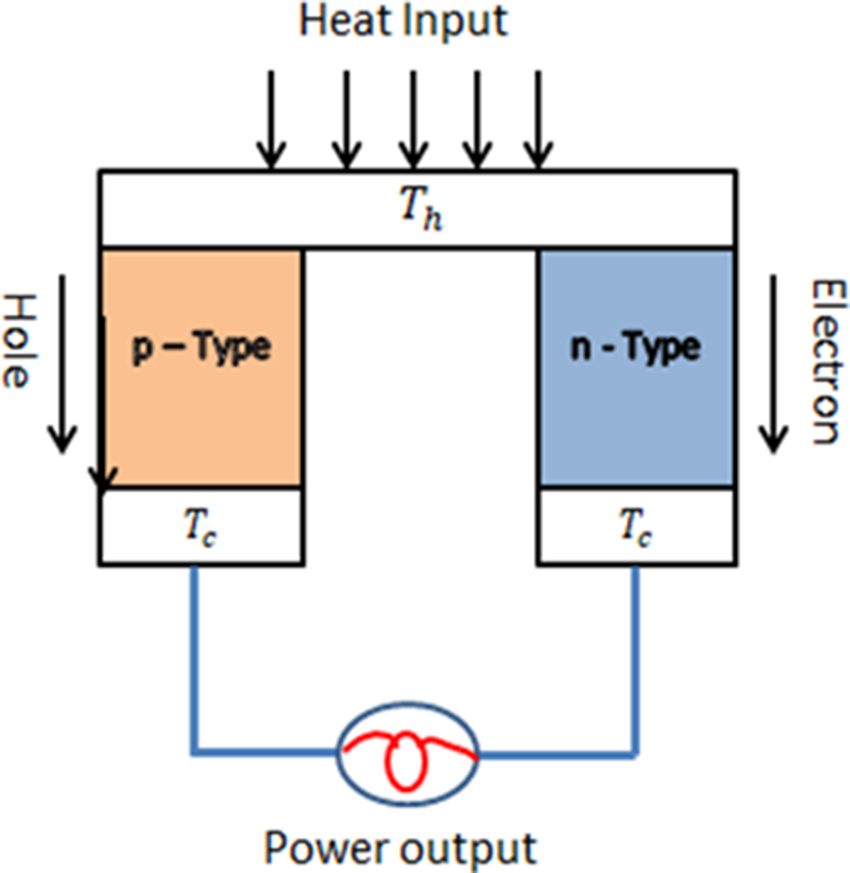
Figure 1: Thermoelectric device Seebeck effect [2]
2.2 Installing the Heat Recovery System
Before installing the system, a measurement for the surface temperature of the Filter Drier Receiver (FDR) was made and it ranged from 32°C to 85°C for an extended period during the day. Eighteen pieces of TEGs are placed between the filter drier receiver of the A/C unit (30 and 15 cm as a high and diameter, respectively) which can be seen in Fig. 2a and the aluminum structure. The aluminum structure was designed and fabricated with 18 sliding channels to fix the TEGs. The aluminum structure is equipped with two belts to tightly, as shown in Fig. 2b. TEGs were installed in the aluminum structure’s sliding channel, and on the other side of the structure, a 3.0 mm thickness heat sink was installed to increase the heat transfer process.
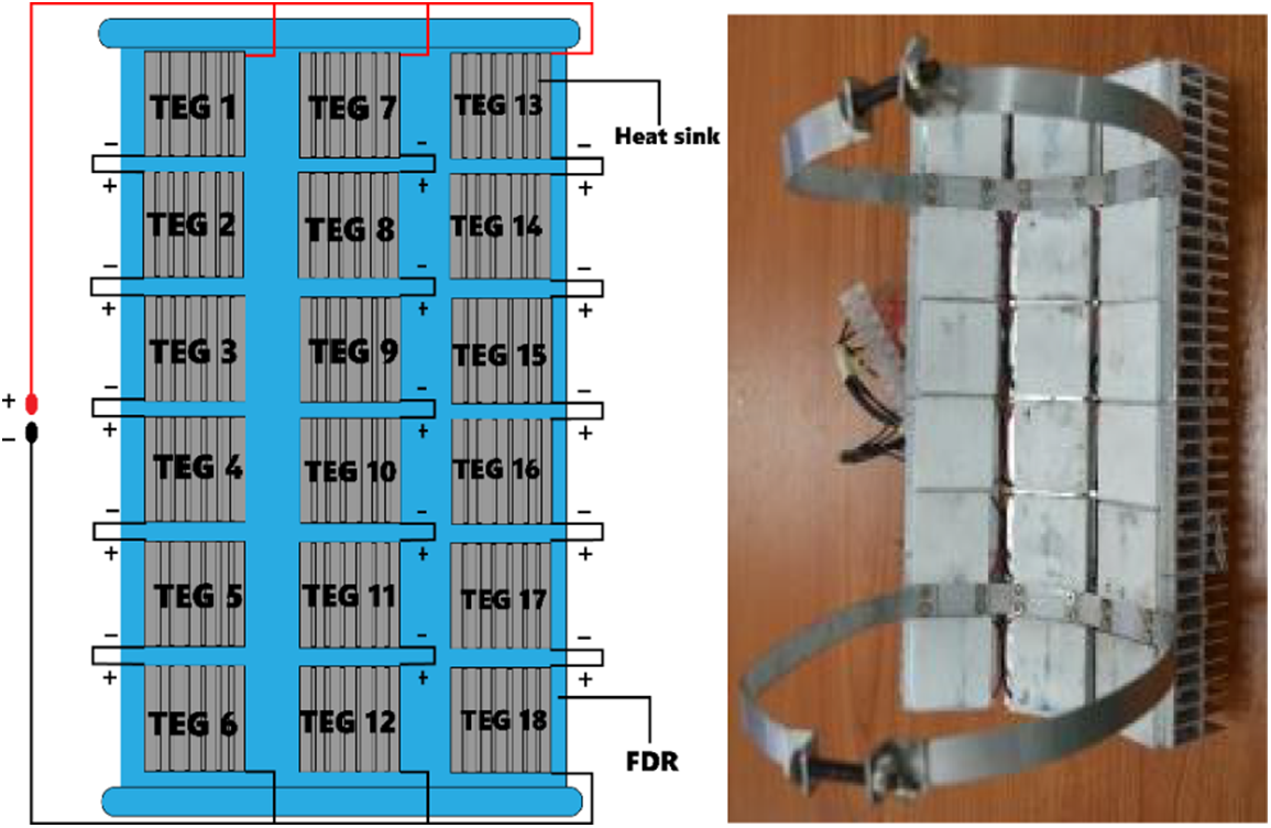
Figure 2: (a) Sketch of the filter drier receiver of the A/C unit with TEG installed, (b) Aluminum frame with 18 TEG
Due to the cylindrical shape of the FDR, a small size of TEG was used to facilitate installation. To match the temperature range of FDR, the TEGs type SP1848 27154 SA in Fig. 3 was used, which consists of Bismuth Telluride material
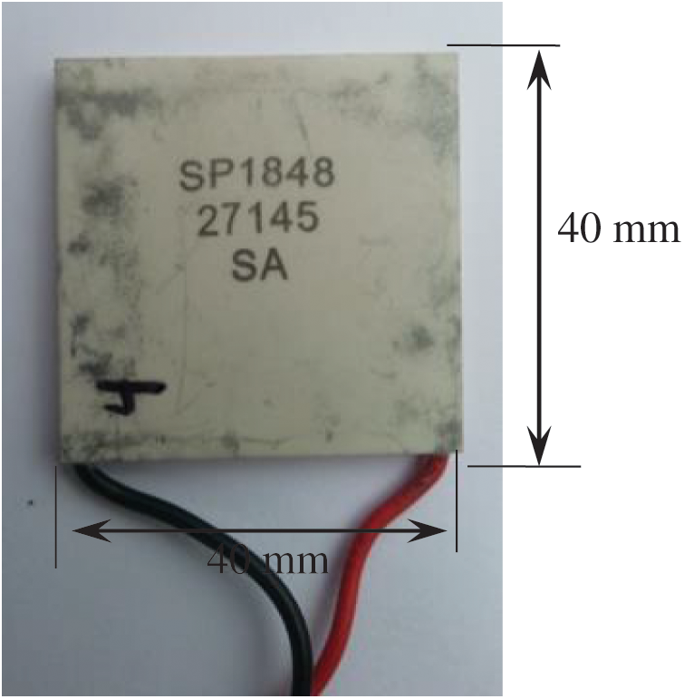
Figure 3: SP1848 27154 SA thermoelectric generator
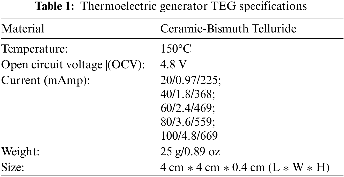
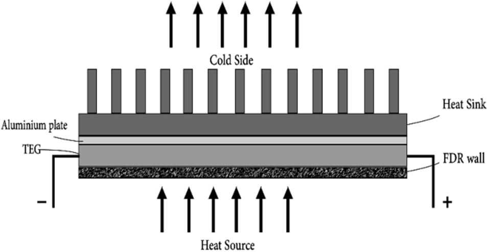
Figure 4: Schematic diagram for the TEG unit installation
The waste heat recovery system was installed on (22 HP) A/C, as shown in Fig. 5. TEGs are arranged in three lines with no air gap to guarantee a high heat transfer rate. Thermal paste was added; however, due to the vibration of the whole unit, the paste was damaged, causing an air gap; therefore, it was removed from the system. The system was connected to an electrical circuit consisting of a boost converter to reduce power loss and make it more stable. The refrigerant with high pressure/temperature liquid was collected from four 5.5 HP compressors in the filter dryer to absorb moisture. Several thermocouples were attached to the FDR to measure its surface temperature, mainly over the drier surface and the heat sink.
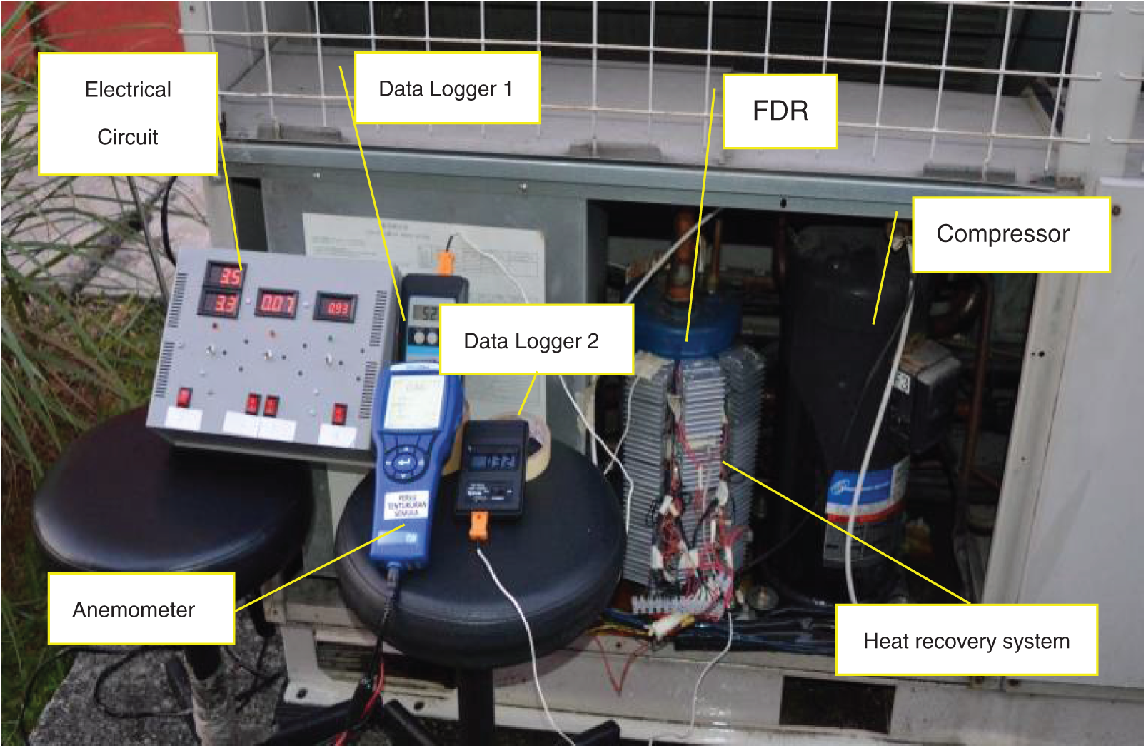
Figure 5: Harvesting system with the electrical circuit and accessories devices
To produce the max power possible for charging the batteries, the voltage should be increased by more than 4.0 V by connecting the TEG in series. Moreover, the current needs to be raised as possible by connecting TEGs in parallel to avoid delay in charging. Considering TEG that was used in the study, it produces 0.97 V and 225 mA with geometrical characteristics of 40, 40, 4.3 mm, respectively [37]. Therefore, the 18-TEGs were installed in 3 lines, each line equipped with 6-TEGs that are connected in series to raise product voltage; then 3 lines were installed in parallel to raise the output current as shown in Fig. 2.
One of the figured issues is the instability of the voltage with the operation of the A/C unit, which could be solved by designing a novel electrical charging circuit. The circuit consists of one current gauge, three voltage gauges, several electric resistances, diodes, two convertors, four manual switches, and one auto-switch. The switches are used to control the electrical circuit. 9 V batteries, as shown in Fig. 6, were used to operate the gauges as these will not be needed for the practical use of the system. The charging voltage rises in two stages, stage 1 from 0.9 to 5.0 V using (DC-DC Convertor USB Module 600 Ma) and stage 2 from 3.5 to 12 V using (GERI XL6009DC-DC Converter 3.0–32 V to 5.0–35). The schematic in Fig. 7 represents the electrical circuit that is sketched by the express SCH computer program. An EXIT emergency sign represented by 4 LEDs was used to be illuminated using the delivered power as shown in Fig. 8.
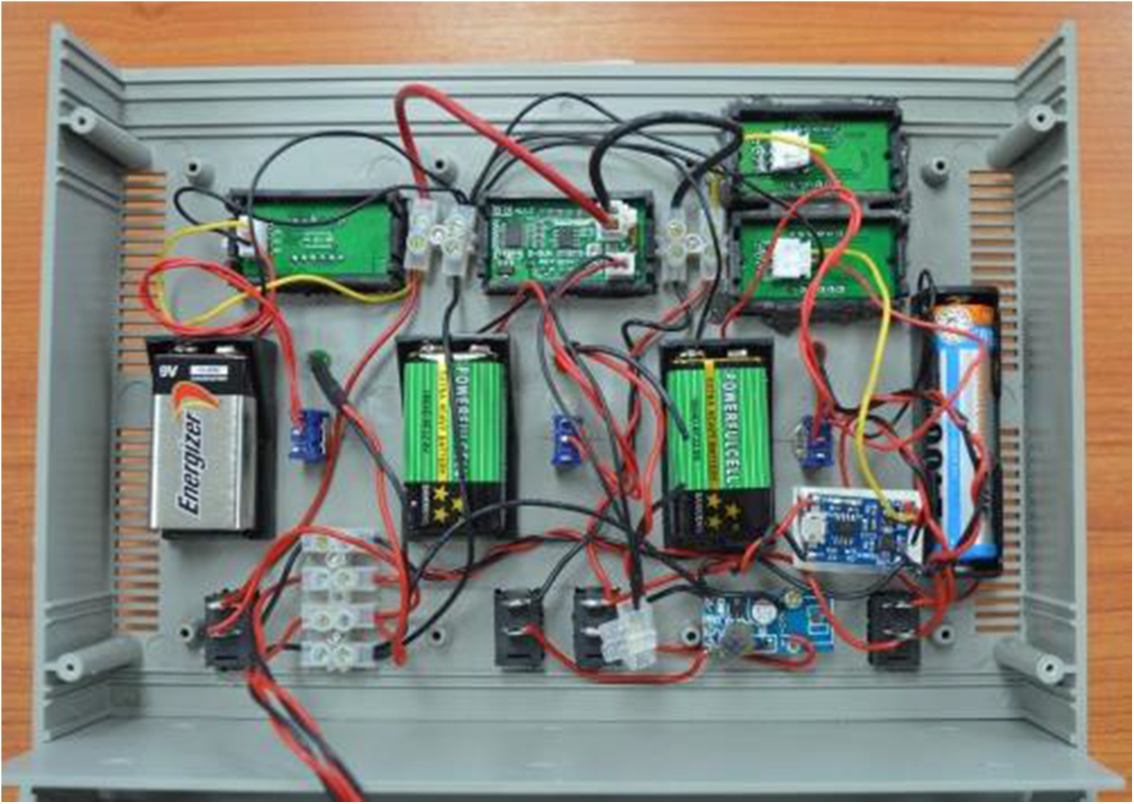
Figure 6: Electric circuit contents
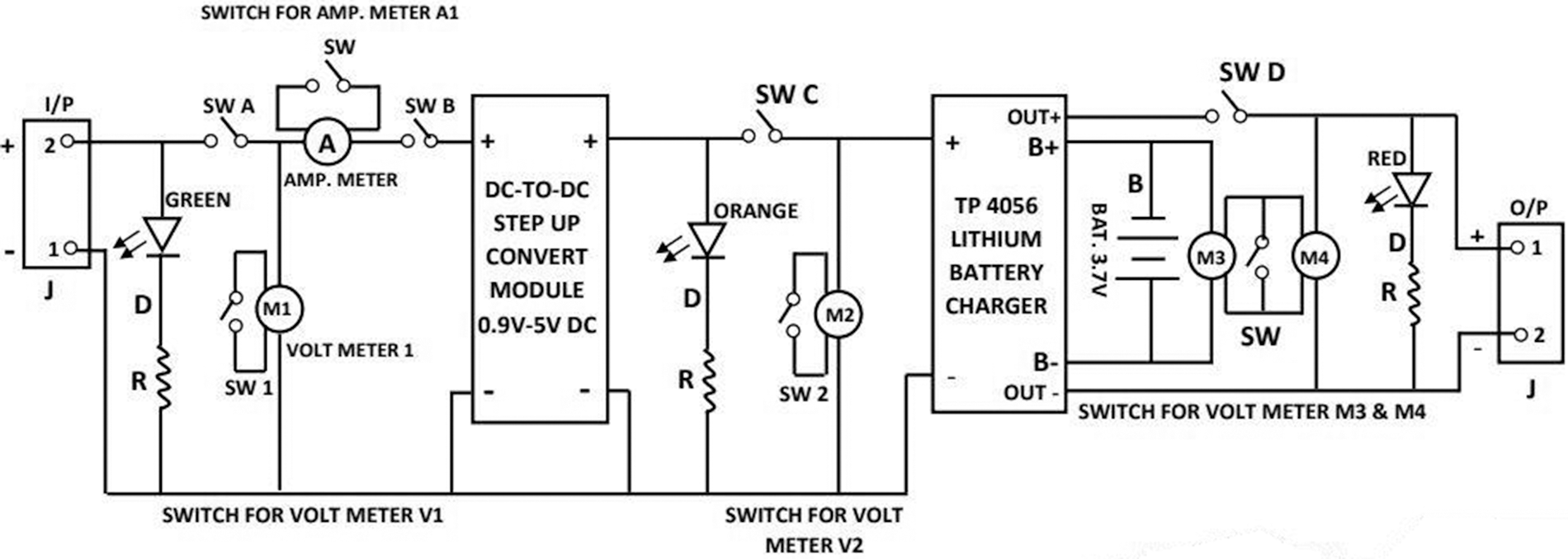
Figure 7: Schematic diagram of the electrical circuit
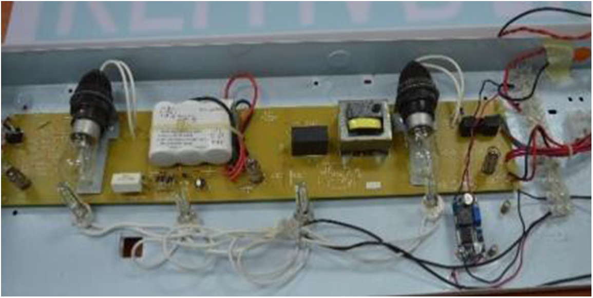
Figure 8: Four LED inside (EXIT) sign
An external load is needed to employ the produced power and measure the system’s efficiency. Therefore, an EXIT emergency sign was used to be illuminated using the delivered power. The original AC bulbs of the illuminated exit sign were replaced with 4-LED (DC and 12 V), as shown in Fig. 8. The sign was equipped with a 3.5 V battery, which receives charge from DC-current generated from TEGs.
4 Theoretical Efficiency Calculation
In addition to the experimental measurement of the system’s efficiency, a theoretical method was also considered in the paper. Assumptions have been made in the analysis of TEG, where the thermal flow through TEG will be considered a steady state. The thermal conductivity in the (p, n) unit is constant. Because the thermal resistance of TEG material is too small, the study will ignore it. Also, ignore the resistance of the connections to heat transfer, heat radiation, the gas between gaps, and axial heat conduction and will consider only perpendicular flow direction [32]. Two ways can be used to estimate efficiency and evaluate the performance of TEG. Firstly, utilized equations of Figure of Merit (FOM); secondly, using equations of heat flow through TEG.
4.1 Figure of Merit Method (FOM)
The Figure of Merit (FOM) (Z) is presented in Eq. (1) and dimensionless Figure of Merit (ZT) in Eq. (3) [9]. These equations are applied to evaluate the efficiency of both TEG and the material that forms it, where the significant value of (Z) or (ZT) represents the super performance efficiency of TEG [4,9].
where:
And
where:
Other criteria for Seebeck performance are the Seebeck effect coefficient (S) (thermo-powers), where the perfect TEG effect is coupled with a high Seebeck coefficient [4,9,35].
The link between FOM and the maximum efficiency of TEG is [4,35,38,39]
The Seebeck coefficient
The waste heat travelled from the FDR cylinder of A/C to the TEG pieces and then to the surrounding through the heat sink. Part of the heat that reaches TEG will convert to electrical energy, and the other part is expelled either as a heat loss from the thin sides of TEG or rejected to the surrounding through the heat sink. The energy balance in TEG will be [35]
Then the TEG output power may be written as [9,35]
Or
Also, the resistance of the external load
The theorem of the Maximum Power Transfer presented that in a DC network with a finite internal resistance, the load resistance must match the source resistance in order to produce the maximum amount of external power [35]. Therefore, the internal resistance of TEG
Thermal conductivity (k) of the Seebeck effect can be computed via utilized net heat transfer from the cold side of TEG; thus, thermal conductivity per meter (
Generally, the conversion efficiency of TEG can be calculated by comparing the energy supplied to the load to the thermal energy subjected at the hot junction [4,35,41]
Or
Then
To compute the heat transfer to the surrounding through the fins of the heat sink, Newton’s law of cooling where explains the phenomena of convection heat transfer in terms of
The effectiveness of the suggested module relies on the variation in temperature between the two surfaces of the TEG. One of the main variables affecting the TEG’s performance is the climate. The three main climate conditions were air velocity, ambient temperature (Tamb), and relative humidity. Firstly, a measurement for these parameters was made over 40 min period. The results showed a change in the relative humidity (RH) and temperature with a rate of 6.0% in RH and
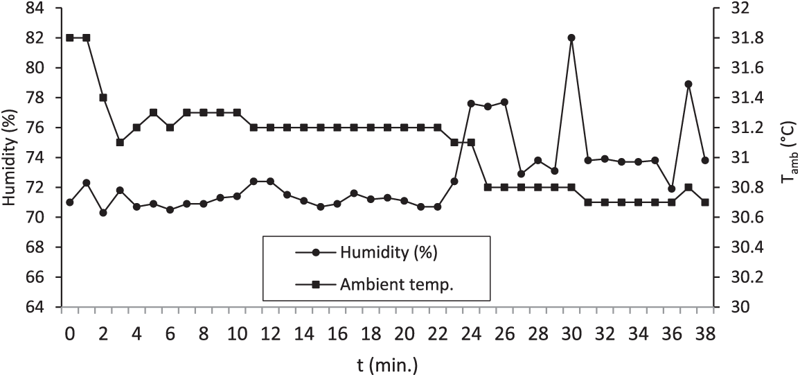
Figure 9: Variation of the ambient temperature and relative humidity (RH) with the time
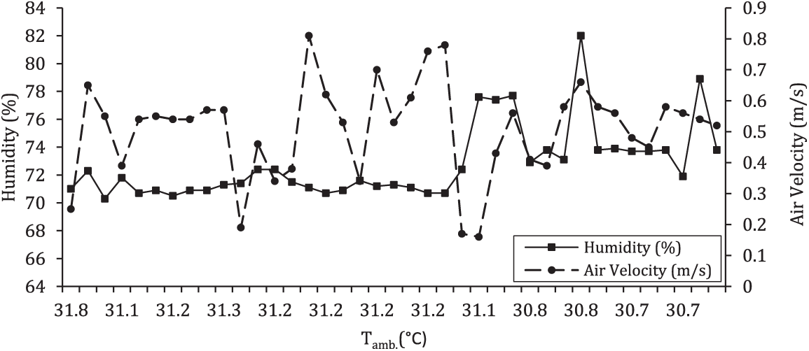
Figure 10: Variation of the air velocity and relative humidity with ambient temperature
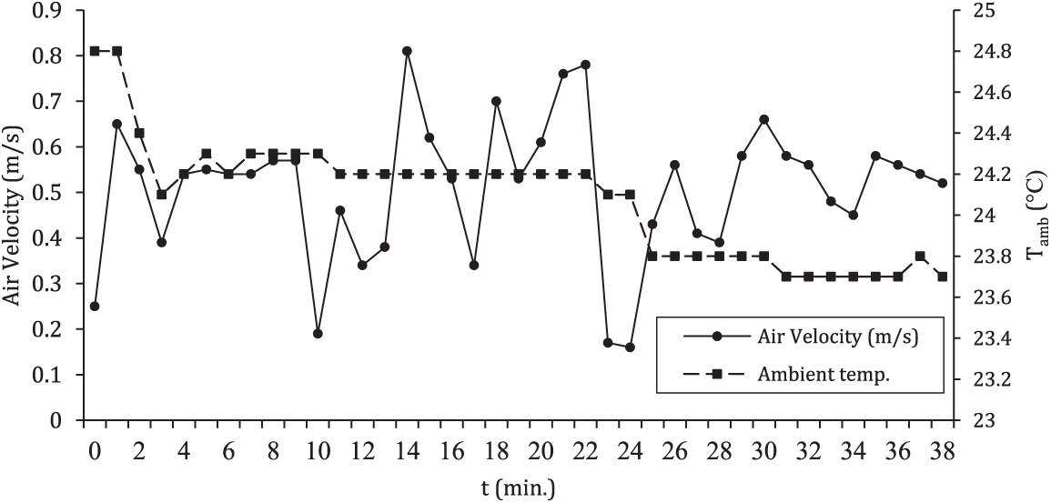
Figure 11: Variation of the ambient temperature and air velocity with the time
From the above, it can be concluded that it is difficult to study all climate variables and their impact on power generation using TEG at once. Each parameter should be examined separately, as supported by [43,44]. Therefore, four days with different climatic characteristics, namely, (a cold-humid-windy day, a cold-humid day, a hot-humid day, and the last hot-humid-windy) were chosen for this study.
Initially, the effect of the different climate variables on the surface temperature of the FDR was investigated. It was noted that the measured surface temperature of the FDR equals 61.5°C, 61.6°C, 62.4°C and 62.2°C for a cold-humid-windy day, a cold-humid day, a hot-humid day, and a hot-humid-windy, respectively (Fig. 12). It should be mentioned that this difference in the temperature of the FDR surface could be regarded to the change in the AC unit operation. The impact of this difference in the surface temperature of the FDR on the produced voltage is insignificant. However, since the production of the power in the TEG alters with the temperature difference between its two faces, the effect of the climate on its performance is also important. It was noticed that for the cold-humid-windy climate, the system generates voltages higher than the rest of the suggested weather conditions with 5.2 V–0.15 Amp-when RH is 82%-and wind speed is 0.2 m/s, as shown in Fig. 13. It can be attributed to the combined climate characteristics which increase the heat transfer by a heat sink, which provides a temperature alteration between the two sides of the TEG and increases the production of power. Moreover, the results showed that there is stability in the cold side temperature of the TEG system in most of the operating times in one day in comparison with the temperature on the side that is hot of the system, as shown in Fig. 12.
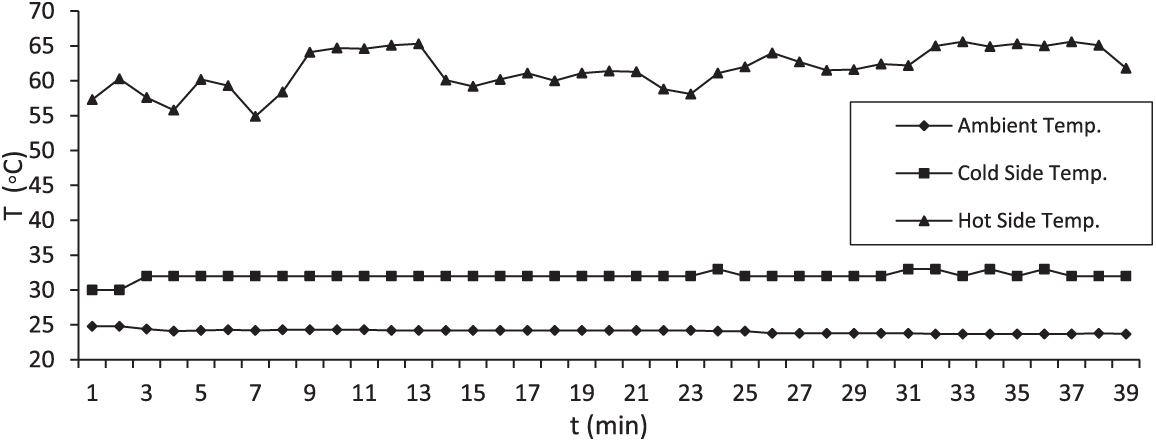
Figure 12: Temperature variation of the cold side, hot side, and ambient temperature in one day
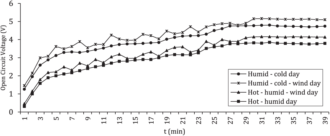
Figure 13: Open-circuit-voltage (OCV) variation for four days with different climate specifications
Fig. 13 shows all the various climatic conditions; the generated voltage starts small and then increases to stabilize after about 30 min of operation. This means that there is a need for more cooling of the cold side to raise the temperature difference and thus increase the voltage significantly since the temperature of the hot side cannot be increased because the heat source is constant. According to previous studies, the increase in wind speed increases the heat transfer in the heat sink, which leads to a rise in voltage production. This is evident in Fig. 11. Still, its effect appears negligible. The reason may be a result of the system not being directly exposed to the air.
The data obtained from the TEG system operation indicated that there were variations in the open and closed-circuit voltage values. This was attributed to the fact that the voltage output of the TEG is influenced by the variance in the temperature between its hot and cold faces. It also was noted that the open circuit voltage (OCV) starts small and increases over time until it stabilizes after about 30 min of operation, while the CCV starts with a high value and begins to decrease and then stability as shown in Fig. 14. The reason for this decrease in the value of the close circuit voltage is the stability in the process of cooling the system at the same time, where the load of the system increases. It is worth mentioning that the measuring of the load voltage was performed at a different time than the open circuit one.
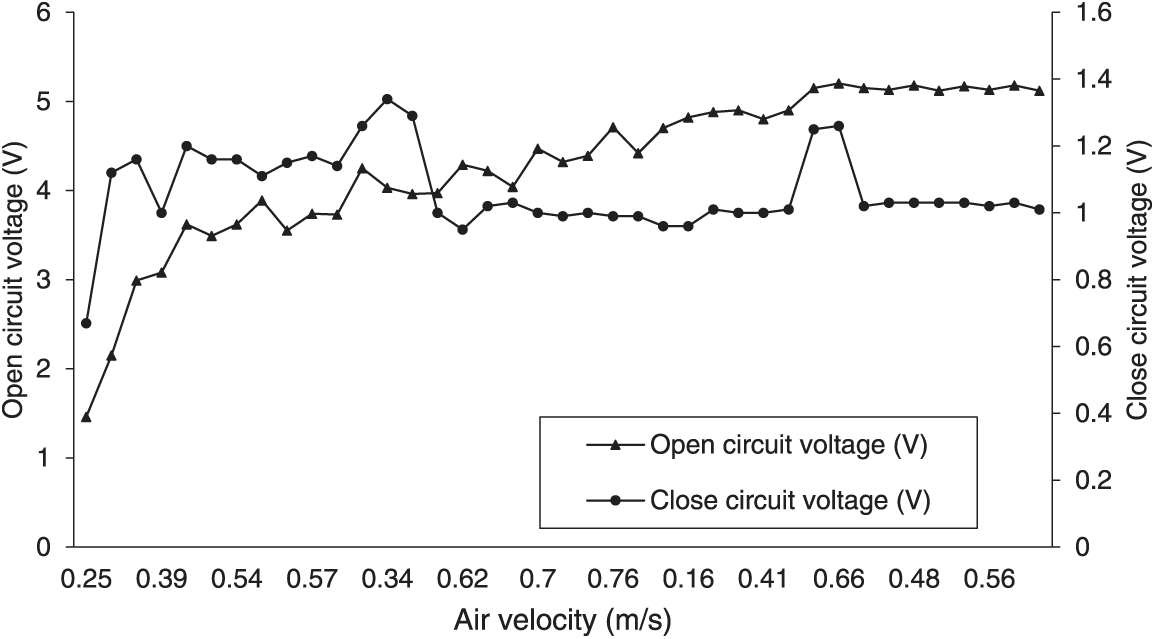
Figure 14: Change of voltage in open circuits for one day with air velocity
As summarized that there is voltage instability with time and climate variation. Therefore, after electrical transformers, the stabilized value of the generated voltage, as well as raising the voltage to larger values, which is shown in Fig. 15. Finally, after operating the system under optimum properties of weather (cold-humid-windy day), the tests show 5.16 V and 0.15 Amp as a maximum value obtained at a close circuit system with a noticeable increase in the output power, which can be seen in Fig. 16. These values are acceptable for charging one battery with 3.5 V, where the battery voltage increase 0.1 V/20 min charging.
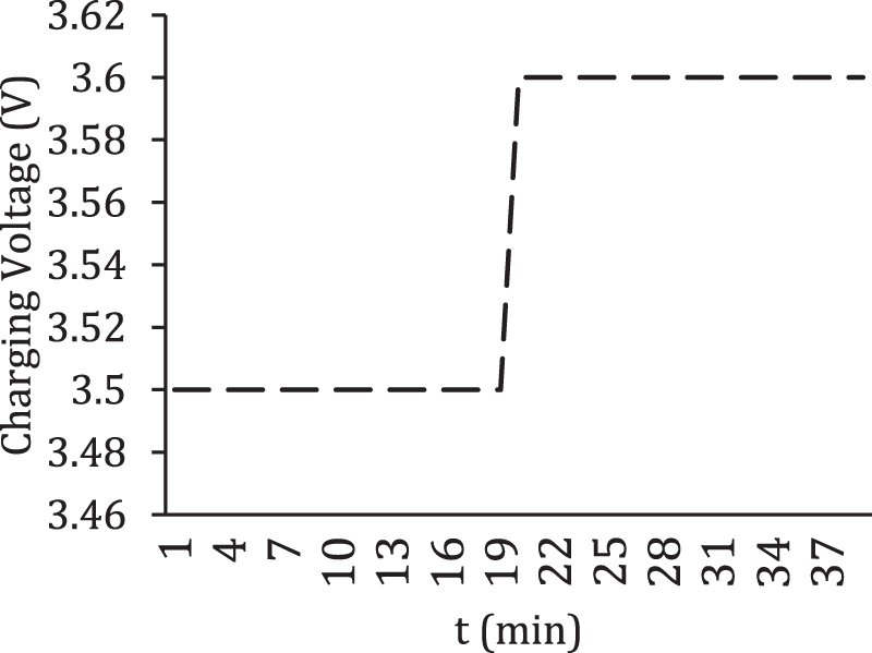
Figure 15: Variation of charging voltage with time
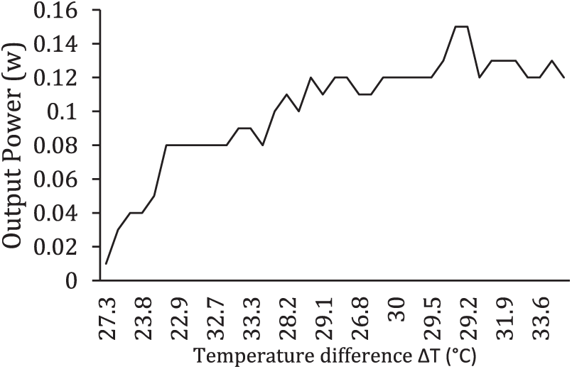
Figure 16: Variation of output power progress with temperature difference
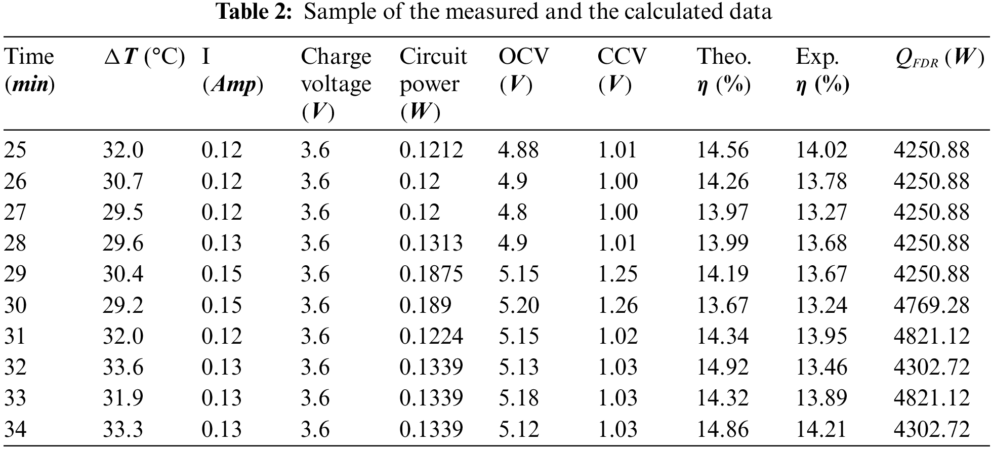
In the current system, the theoretical value of the system’s power and efficiency can be computed by Eqs. (6) and (8), whereas the experimental efficiency is calculated using Eq. (13). The experimental result showed that the system produces maximum efficiency of ≈ 13.5% and a theoretical one of 15% after a 13 min run, which is shown in Fig. 17. A clear fluctuation in the efficiency value with time was absorbed due to unstable weather conditions. In general, the theoretical and experimental findings are in reasonable accordance, with the highest difference between them being 6.4% occurring following a 40-min run. It can be seen that the theoretical efficiency is higher than the experimental one, this can be attributed to the ideal value of the ZT term in the theoretical efficiency calculation. On another hand, for experimental efficiency, various factors that can affect its value such as the unstable wind speed, temperature fluctuation and gap in the contact region between the TEG with the surface of the FDR. Samples of the evaluated and calculated data that were used to estimate the efficiency are presented in Table 2. This data covered 10 min of one selected measuring period of a cold-humid-windy day.
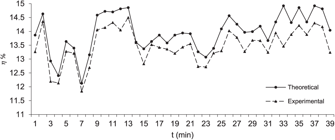
Figure 17: Comparison between theoretical and experimental system efficiency
The evaluation of the illuminated EXIT sign performance after attaching it to the proposed system showed better performance. A light meter was used to measure the light intensity of the illuminated exit sign; the practical test gives 194.3 LUX of 12V-LED, whereas the original ac bulbs recorded 140.5 LUX.
The new power generating system contributes to the environment in various ways, such as saving time required for replacing of battery and saving maintenance cost, increase battery life span, which impacts device life span essentially in devices that are difficult or impossible to exchange batteries, reduces the overall size of some electronic devices and utilize from waste energy.
The paper intends to convert the waste heat rejected from the filter drier receiver (FDR) of an air conditioning unit into useful energy by utilizing a thermoelectric generator (TEG) based on the Seebeck effect. The power generating system was designed to incorporate a low-power battery for rechargeability. Additionally, a novel electrical circuit was developed to address the voltage fluctuations generated by the TEG. The results showed good agreement between the experimental system efficiency and the theoretical efficiency, with a maximum deviation of error of ±6%. The experimental efficiency was found to be 13%, while the theoretical efficiency was 15%. The maximum values obtained from a closed-circuit system were 5.16 V and 0.15 A, leading to a noticeable improvement in the output power. These values are sufficient for charging a single battery with 3.5 V, which increases by 0.1 V per 20 min of charging. If expanded to include additional air conditioning units in buildings, this system holds great promise.
Funding Statement: The authors received no specific funding for this study.
Author Contributions: The authors confirm their contribution to the paper as follows: study conception and design, data collection: Ali Jaber Abdulhamed; analysis and interpretation of results: Ali Jaber Abdulhamed and Aws Al-Akam; draft manuscript preparation: Mohmmed H Alkhafaji and Ahmed A. Abduljabbar. All authors reviewed the results and approved the final version of the manuscript.
Conflicts of Interest: The authors declare that they have no conflicts of interest to report regarding the present study.
References
1. Yazawa, K., Shakouri, A. (2011). Cost-efficiency trade-off and the design of thermoelectric power generators. Environmental Science & Technology, 45(17), 7548–7553. https://doi.org/10.1021/es2005418 [Google Scholar] [PubMed] [CrossRef]
2. Kaminaga, T., Yamaguchi, K., Ratnak, S., Kusaka, J., Yousoeta, T. (2018). A study on combustion characteristics of a high compression ratio SI engine with high-pressure gasoline injection 2018. SAE Technical Paper, 2019-24-0106. https://doi.org/10.4271/2019-24-0106 [Google Scholar] [CrossRef]
3. Wang, T., Zhang, Y., Peng, Z., Shu, G. (2011). A review of researches on thermal exhaust heat recovery with Rankine cycle. Renewable and Sustainable Energy Reviews, 15(6), 2862–2871. https://doi.org/10.1016/j.rser.2011.03.015 [Google Scholar] [CrossRef]
4. Kong, L. B., Li, T., Hng, H. H., Boey, F., Zhang, T. et al. (2014). Waste energy harvesting: Mechanical & thermal energies. New York: Springer. https://doi.org/10.1007/978-3-642-54634-1 [Google Scholar] [CrossRef]
5. Ahıska, R., Mamur, H. (2014). A review: Thermoelectric generators in renewable energy. International Journal of Renewable Energy Research, 4(1), 128–136. [Google Scholar]
6. Massaguer, E., Massaguer, A., Montoro, L., Gonzalez, J. R. (2014). Modelling analysis of longitudinal thermoelectric energy harvester in low-temperature waste heat recovery applications. Applied Energy, 140, 184–195. https://doi.org/10.1016/j.apenergy.2014.12.005 [Google Scholar] [CrossRef]
7. Zhao, Y., Wang, S., Ge, M., Liang, Z., Liang, Y. et al. (2018). Performance analysis of automobile exhaust thermoelectric generator system with media fluid. Energy Conversation Management, 171(23), 427–437. https://doi.org/10.1016/j.enconman.2018.06.006 [Google Scholar] [CrossRef]
8. Massaguer, A., Massaguer, E., Comamala, M., Pujol, T., González, J. R. et al. (2018). A method to assess the fuel economy of automotive thermoelectric generators. Applied Energy, 222, 42–58. https://doi.org/10.1016/j.apenergy.2018.03.169 [Google Scholar] [CrossRef]
9. Jouhara, H., Żabnieńska-Góra, A., Khordehgah, N., Doraghi, Q., Ahmad, L. et al. (2021). Thermoelectric generator (TEG) technologies and applications. International Journal of Thermo Fluids, 9(2), 1–17. https://doi.org/10.1016/j.ijft.2021.100063 [Google Scholar] [CrossRef]
10. Orr, B., Akbarzadeh, A., Mochizuki, M., Singh, R. (2015). A review of car waste heat recovery systems utilising thermoelectric generators and heat pipes. Applied Thermal Engineering, 101, 490–495. https://doi.org/10.1016/j.applthermaleng.2015.10.081 [Google Scholar] [CrossRef]
11. Orr, B., Akbarzadeh, A., Lappas, P. (2017). An exhaust heat recovery system utilizing thermoelectric generators and heat pipes. Applied Thermal Engineering, 126, 1185–1190. https://doi.org/10.1016/j.applthermaleng.2016.11.019 [Google Scholar] [CrossRef]
12. Alsabahi, H. K., Alkhakani, A. J., Adam, N. M., As, A. (2015). Review of potential thermoelectric energy harvesting using seebeck effect. International Journal of Engineering Research & Technology, 4(11), 173–177. [Google Scholar]
13. Hsiao, Y., Chang, W., Chen, S. (2010). A mathematic model of thermoelectric module with applications on waste heat recovery from automobile engine. Energy, 35, 1447–1454. https://doi.org/10.1016/j.energy.2009.11.030 [Google Scholar] [CrossRef]
14. He, W., Wang, S., Lu, C., Zhang, X., Li, Y. (2016). Influence of different cooling methods on thermoelectric performance of an engine exhaust gas waste heat recovery system. Applied Energy, 162, 1251–1258. https://doi.org/10.1016/j.apenergy.2015.03.036 [Google Scholar] [CrossRef]
15. Wang, Y., Li, S., Xie, X., Deng, Y., Liu, X. et al. (2018). Performance evaluation of an automotive thermoelectric generator with inserted fins or dimpled-surface hot heat exchanger. Applied Energy, 218(8), 391–401. https://doi.org/10.1016/j.apenergy.2018.02.176 [Google Scholar] [CrossRef]
16. Sok, R., Kusaka, J., Nakashima, H., Minagata, H., Dimitriou, P. et al. (2023). Thermoelectric generation from exhaust heat in electrified natural gas trucks: Modeling and analysis of an integrated engine system performance improvement. Journal of Energy Resources Technology, 145(7), 071702-1. https://doi.org/10.1115/1.4056722 [Google Scholar] [CrossRef]
17. Sok, R., Kusaka, J. (2022). Experimental and modeling analysis on thermoelectric heat recovery to maximize the performance of next-generation diesel engines dedicated for future electrified powertrains. Applied Thermal Engineering, 219, 119530. https://doi.org/10.1016/j.applthermaleng.2022.119530 [Google Scholar] [CrossRef]
18. Akçay, H., Gürbüz, H., Topalci, U., Demirtürk, S. (2020). CFD analysis of thermoelectric generator developed for exhaust waste heat recovery in a typical spark ignition engine. El-Cezerî Journal of Science and Engineering, 7(3), 1088–1100. https://doi.org/10.31202/ecjse.724353 [Google Scholar] [CrossRef]
19. Miao, L., Kang, Y. P., Li, C., Tanemura, S., Wan, C. L. et al. (2015). Experimental performance of a solar thermoelectric cogenerator comprising thermoelectric modules and parabolic trough concentrator without evacuated tube. Journal of Electronic Material, 44(6), 1972–1983. https://doi.org/10.1007/s11664-015-3626-7 [Google Scholar] [CrossRef]
20. Kraemer, D., Poudel, B., Feng, H. P., Caylor, J. C., Yu, B. et al. (2011). High-performance flat-panel solar thermoelectric generators with high thermal concentration. Nature Materials, 10(7), 532–538. https://doi.org/10.1038/nmat3013 [Google Scholar] [PubMed] [CrossRef]
21. Li, P., Cai, L., Zhai, P., Tang, X., Zhang, Q. et al. (2010). Design of a concentration solar thermoelectric generator. Journal of Electronic Material, 39(9), 1522–1530. https://doi.org/10.1007/s11664-010-1279-0 [Google Scholar] [CrossRef]
22. Xiao, J. S., Yang, T., Li, P., Zhai, P., Zhang, Q. (2012). Thermal design and management for performance optimization of solar thermoelectric generator. Applied Energy, 93, 33–38. https://doi.org/10.1016/j.apenergy.2011.06.006 [Google Scholar] [CrossRef]
23. Amatya, R., Ram, R. J. (2010). Solar thermoelectric generator for micropower applications. Journal of Electronic Material, 39(9), 1735–1740. https://doi.org/10.1007/s11664-010-1190-8 [Google Scholar] [CrossRef]
24. Baranowski, L. L., Snyder, G. J., Toberer, E. S. (2012). Concentrated solar thermoelectric generators. Energy and Environmental Science, 5(10), 9055–9067. https://doi.org/10.1039/c2ee22248e [Google Scholar] [CrossRef]
25. Matiko, J. W., Grabham, N. J., Beeby, S. P., Tudor, M. J. (2014). Review of the application of energy harvesting in buildings. Measurement Science & Technology, 25(1), 1–25. https://doi.org/10.1088/0957-0233/25/1/012002 [Google Scholar] [CrossRef]
26. Leonov, V. (2013). Thermoelectric energy harvesting of human body heat for wearable sensors. IEEE Sensors Journal, 13(6), 2284–2291. https://doi.org/10.1109/JSEN.2013.2252526 [Google Scholar] [CrossRef]
27. Wang, Z., Leonov, V., Fiorini, P., van Hoof, C. (2009). Realization of a wearable miniaturized thermoelectric generator for human body applications. Sensors and Actuators, A: Physical, 156(1), 95–102. https://doi.org/10.1016/j.sna.2009.02.028 [Google Scholar] [CrossRef]
28. Wong, C. L., Venneker, R., Jamil, A. B. M., Uhlenbrook, S. (2011). Development of a gridded daily hydrometeorological data set for Peninsular Malaysia. Hydrological Processes, 25(7), 1009–1020. https://doi.org/10.1002/hyp.7654 [Google Scholar] [CrossRef]
29. Wong, C. L., Venneker, R., Uhlenbrook, S., Jamil, A. B. M., Zhou, Y. (2009). Variability of rainfall in Peninsular Malaysia, Hydrol. Hydrology and Earth System Sciences Discussions, 6(7), 5471–5503. https://doi.org/10.5194/hessd-6-5471-2009 [Google Scholar] [CrossRef]
30. Mahlia, T. M., Masjuki, H., Saidur, R., Amalina, M. (2004). Cost–benefit analysis of implementing minimum energy efficiency standards for household refrigerator-freezers in Malaysia. Energy Policy, 32, 1819–1824. https://doi.org/10.1016/S0301-4215(03)00169-1 [Google Scholar] [CrossRef]
31. Ismail, B. I., Ahmed, W. H. (2009). Thermoelectric power generation using waste-heat energy as an alternative green technology. Recent Patents on Electrical Engineering, 2(1), 27–39. https://doi.org/10.2174/1874476110902010027 [Google Scholar] [CrossRef]
32. Wang, Y., Dai, C., Wang, S. (2013). Theoretical analysis of a thermoelectric generator using exhaust gas of vehicles as heat source. Applied Energy, 112(10), 1171–1180. https://doi.org/10.1016/j.apenergy.2013.01.018 [Google Scholar] [CrossRef]
33. Kossyvakis, D. N., Vossou, C. G., Provatidis, C. G., V.Hristoforou, E. (2015). Computational and experimental analysis of a commercially available Seebeck module. Renewable Energy, 74(1–4), 1–10. https://doi.org/10.1016/j.renene.2014.07.024 [Google Scholar] [CrossRef]
34. Ismail, B. I., Alabdrabalnabi, N. (2014). Design and performance characteristics of a portable solar-driven thermoelectric heat pump under thunder bay extreme cold conditions in Northwestern Ontario, Canada. Journal of Green Engineering, 4, 117–134. https://doi.org/10.13052/jge1904-4720.422 [Google Scholar] [CrossRef]
35. Faraji, A. Y., Akbarzadeh, A. (2013). Design of a compact, portable test system for thermoelectric power generator modules. Journal of Electronic Material, 42(7), 1535–1541. https://doi.org/10.1007/s11664-012-2314-0 [Google Scholar] [CrossRef]
36. Ming T., Wu Y., Peng C., Tao Y. (2014). Thermal analysis on a segmented thermoelectric generator. Energy, 80(3), 388–399. https://doi.org/10.1016/j.energy.2014.11.080 [Google Scholar] [CrossRef]
37. Chen, Y., Hou, X., Ma, C., Dou, Y., Wu, W. (2018). Review of development status of Bi2Te3-based semiconductor thermoelectric power generation. Advance Material Scientific Engineering, 1–9. https://doi.org/10.1155/2018/1210562 [Google Scholar] [CrossRef]
38. Champier, D. (2017). Thermoelectric generators: A review of applications. Energy Conversion and Management, 140, 167–181. https://doi.org/10.1016/j.enconman.2017.02.070 [Google Scholar] [CrossRef]
39. Jaziri, N., Boughamoura, A., Müller, J., Mezghani, B., Tounsi, F. et al. (2020). A comprehensive review of Thermoelectric Generators: Technologies and common applications. Energy Reports, 6(7), 264–287. https://doi.org/10.1016/j.egyr.2019.12.011 [Google Scholar] [CrossRef]
40. Yue, R., Xu, J. (2012). Poly(3,4-ethylenedioxythiophene) as promising organic thermoelectric materials: A mini-review. Synthetic Metals, 162(11–12), 912–917. https://doi.org/10.1016/j.synthmet.2012.04.005 [Google Scholar] [CrossRef]
41. Zabek, D., Morini, F. (2019). Solid state generators and energy harvesters for waste heat recovery and thermal energy harvesting. Thermal Science and Engineering Progress, 9(2), 235–247. https://doi.org/10.1016/j.tsep.2018.11.011 [Google Scholar] [CrossRef]
42. Holman, J. P. (2010). Heat transfer. McGraw-hill series in mechanical engineering, 10th edition. USA: Math Mcgraw-Hill Book Company. https://doi.org/10.1080/01973762.1999.9658510 [Google Scholar] [CrossRef]
43. Kitagawa, K. (1999). Effect of humidity and small air movement on thermal comfort under a radiant cooling ceiling by subjective experiments. Energy and Buildings, 30(2), 185–193. https://doi.org/10.1016/S0378-7788(98)00086-3 [Google Scholar] [CrossRef]
44. Mekhilef, S., Saidur, R., Kamalisarvestani, M. (2012). Effect of dust, humidity and air velocity on efficiency of photovoltaic cells. Renewable and Sustainable Energy Reviews, 16(5), 2920–2925. https://doi.org/10.1016/j.rser.2012.02.012 [Google Scholar] [CrossRef]
Cite This Article
 Copyright © 2023 The Author(s). Published by Tech Science Press.
This work is licensed under a Creative Commons Attribution 4.0 International License , which permits unrestricted use, distribution, and reproduction in any medium, provided the original work is properly cited.
 Downloads
 Citation Tools