
 Submit a Paper
 Propose a Special lssue
 Open Access
ARTICLE
Simulation Research on Coal-Water Slurry Gasification of Oil-Based Drill Cuttings Based on Fluent
School of Petroleum Engineering, Changzhou University, Changzhou, China
* Corresponding Author: Hailong Yu. Email:
Energy Engineering 2023, 120(9), 1963-1977. https://doi.org/10.32604/ee.2023.027897
Received 20 November 2022; Accepted 14 February 2023; Issue published 03 August 2023
 View Full Text
 Download PDF
Abstract
In this paper, based on Fluent software, a five-nozzle gasifier reactor was established to simulate the gasification process of oil-based drill cuttings coal-water slurry. The influence of concentration and oxygen/carbon atomic ratio on the gasification process of oil-based drill cuttings coal-water slurry was investigated. The results show that when the oxygen flow is constant, the outlet temperature of gasifier decreases, the content of effective gas increases, and the carbon conversion rate decreases with the increase of concentration; When the ratio of oxygen to carbon atoms is constant, the effective gas content rises and the temperature rises with the increase of the concentration, and the carbon conversion rate reaches the maximum value when the concentration of oil-based drill cuttings coal-water slurry is 65%; When the concentration is constant, the effective gas content decreases and the outlet temperature rises with the increase of the oxygen/carbon atom ratio, and the carbon conversion rate reaches 99.80% when the oxygen/carbon atom ratio is 1.03. It shows that this method can effectively decompose the organic matter in oil-based drill cuttings and realize the efficient and cooperative treatment of oil-based drill cuttings.Graphic Abstract

Keywords
Nomenclature
| OBDC | Oil-Based Drill Cuttings |
| CWS | Coal-Water Slurry |
| OBDC-CWS | Oil-Based Drill Cuttings Coal-Water Slurry |
| OCR | Oxygen-Carbon Ratio |
In 2020, China’s shale gas production reached 3 × 10¹⁰ m3 and is growing rapidly. It is expected to exceed 9 × 10¹⁰ m3 by 2030, requiring at least 15,000 new wells [1]. It is estimated that each well will produce 700 t of oil-based drill cuttings (OBDC), but over 9 × 10⁶ t of OBDC will be produced cumulatively. Since the oil phase of OBDC is mainly diesel oil and heavy oil, the oil content can reach 14.14%~26.21% [2,3], so OBDC have a certain utilization value. OBDC have been classified as hazardous waste in many countries due to their polluting nature [4]. The safe and resource-efficient treatment of drilling cuttings has always been a difficult problem for the petrochemical industry.
With the deepening of research on OBDC treatment technology in the world, the harmless treatment and resource utilization of OBDC will be gradually realized, from the initial landfilling [5], incineration [6], and hardening [7], to solvent extraction [8], biodegradation treatment [9], thermal desorption [10], and high temperature cracking treatment [11]. But these processing methods more or less have certain defects or technical barriers. In the long run, the traditional treatment methods (landfill, solidification, etc.) have a higher risk of secondary pollution, while the emerging treatment methods have significant bottleneck problems, such as high energy consumption and poor continuous treatment capacity. Compared to these treatment methods, the technology of using gasifiers to treat such higher calorific value pollutants is relatively mature [12–15]. The high temperature (1575 K) produced in the gasification process can avoid the production of dioxins, furans, and other harmful components [16].
High-temperature gasification is different from the simple pyrolysis process. Pyrolysis energy consumption is often very high, but the material will release a lot of heat in the gasification process, which is conducive to reducing power consumption in the treatment process. For OBDC, which is such difficult hazardous wastes, the low processing temperature makes it difficult to treat them thoroughly. On the one hand, it is advantageous to reduce the high cost caused by energy consumption to choose high-temperature gasification as a treatment for OBDC. On the other hand, higher temperatures allow organic matter in OBDC to decompose completely.
The difference in composition between OBDC and coal results in different gasification properties, including maximum flame temperature, syngas composition, and carbon conversion. It is innovatively proposed that the OBDC, coal, additives, and water are prepared into oil-based drill cuttings coal-water slurry (OBDC-CWS) in a certain proportion, and the conventional gasification process can be used to achieve the purpose of OBDC treatment. To obtain a better gasification treatment effect, detailed numerical simulation is essential. Choi et al. [17] analyzed its influence on the gasification result according to the operating parameters of the gas bed gasifier. Yu et al. [18] studied the influence of the concentration of coal-water slurry (CWS) on the result of CWS gasification by using a two-dimensional geometric model. Watanabe et al. [19] studied the influence of the oxygen-coal ratio on syngas components, carbon conversion, and cold gas efficiency.
Many scholars [20,21] have conducted many studies on gasifiers under different conditions, but the energy of the gas flow upward along the gasifier axis is generally not fully released in the multi-jet gasifiers used in these studies, which leads to the fast burning loss rate of the refractory at the top of the gasification furnace. The 5-nozzle gasifier studied in this paper can prevent this situation, and the dispersion effect of CWS is better under the same processing capacity. The detour amount of materials in the furnace is larger, which prolongs the residence time of materials in the furnace and greatly strengthens the heat and mass transfer processes in the gasifier. At the same time, this treatment method realizes the cooperative treatment of OBDC, provides a reference for the treatment of high calorific value hazardous waste, and solves the problems of the difficulty and low treatment efficiency of OBDC.
In this study, the PDF non-premixed combustion model was used, and the pyrolysis process of combustible particles was solved by the dual-competition pyrolysis model. The turbulence model was modeled using the Standard k-ε model. The Simple algorithm is used to solve the coupling of pressure and velocity of the discrete equations, and the discrete scheme is the PRESTO scheme. The DPM (discrete phase) model is used to set up and solve the multi-step coke reaction of coal slurry combustion. The radiation characteristics of the gasifier are simulated by the P-1 radiation model. By comparing the data predicted by the model with the industrial data, the validity of the model is verified. Through the simulation analysis of different working conditions, the theoretical basis for the next practical application and improvement of the project is provided.
2 Model Establishment and Validation
The simulation calculation process of OBDC-CWS gasification includes descriptions of fluid flow, heat and mass transfer and chemical reaction processes [22]. The basic governing equations used are as follows:
Continuity equation:
Momentum equation:
Energy equation:
Standard k-ε model equation:
Mixing rate equation:
P-1 radiation model equation:
The model is a five-nozzle gasifier combustion chamber, one nozzle is arranged on the top of the combustion chamber, and four nozzles are symmetrically distributed on the side. The angle between the nozzle and the horizontal plane is 45°, 0.9 m from the top of the furnace, the diameter of the gasification chamber is 0.5 m, and the bottom is the outlet of the combustion chamber. The gasifier was modeled using SolidWorks, and the model was meshed by ICEM. The grid type of this model is the hexahedral structured grid, which is divided into 1.86 million, 2.05 million, and 4.8 million grids, respectively. After grid independence verification, the number of grids is determined to be 2.05 million. The specific structure is shown in Fig. 1.
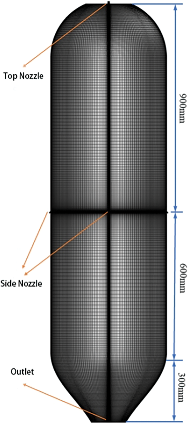
Figure 1: Grid model of gasifier
2.3 Setting of Solution Conditions
The process involved in CWS gasification is very complex. To reduce the difficulty and time required to solve the model [23,24], this study appropriately simplifies the model and makes the following assumptions: The average residence time was used to describe the particle flow; ignoring the atomization of CWS droplets, it is assumed that the coal particles are all spherical and the temperature distribution is uniform (the particle size distribution and diameter distribution of pulverized coal obey Rosin-Rammler law); interparticle radiation and slag deposition are ignored in the simulation; oxidants are oxygen and water vapor [25].
According to the problem studied in this paper, the type of boundary conditions of the model are set as follows: the whole gasification chamber is regarded as the computational domain and defined as Fluid; the four nozzle inlet boundaries are set as mass_flow_inlet boundaries; the boundary condition for the exit is set to Pressure_out and the rest of the boundary is set to Wall. No slip and temperature boundary conditions are used on the wall surface.
Setting model solution: Simple algorithm is used to solve the coupling of pressure and velocity of discrete equations, and the PRESTO scheme is used for discrete equations. Standard k-ε was selected as turbulence model and P1 was selected as radiation model. PDF non-premixed combustion model is used for gas combustion. DPM model is adopted for gas-solid phase, and the interaction between granular phase and continuous phase is considered [26,27].
Convergence criteria: In this paper, the calculation convergence can be considered when the variation of monitored parameters is less than 0.1%.
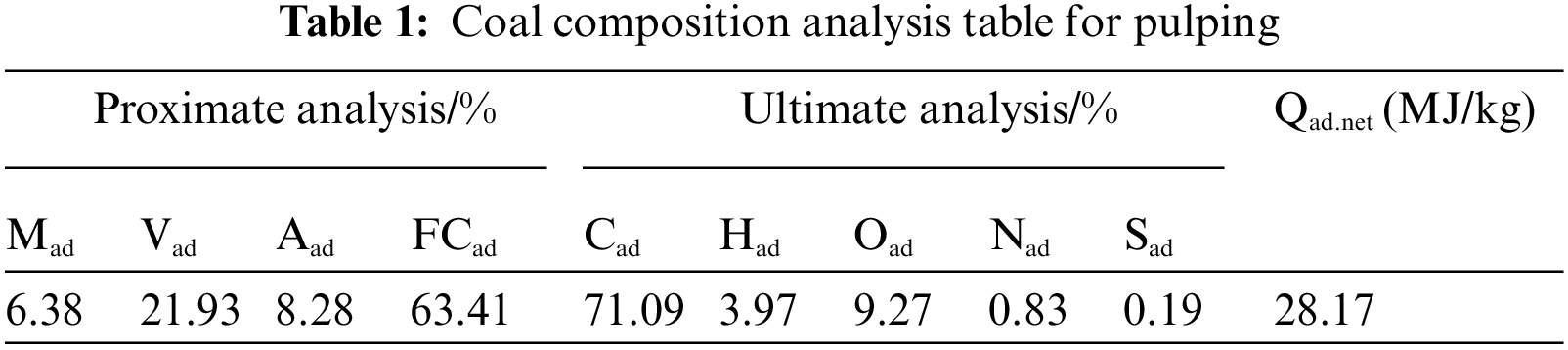
The model is verified by the industrial data in the paper of Sun et al. [28]. The CWS is pressurized by the CWS pump, atomized and mixed with O2 in the nozzle, and sprayed into the gasification chamber at a gasification pressure of 5.9 MPa. The CWS treatment capacity is 84.7 t/h, the CWS flow rate at the entrance of a single nozzle is 4.71 kg/s, and the oxidizer flow rate is 8490 Nm3/h. Oxygen in the oxidizer accounts for 99.8%, and the rest is nitrogen. The concentration of CWS is 60.5%. The following Table 1 shows the proximate analysis and ultimate analysis of CWS made in this plant.
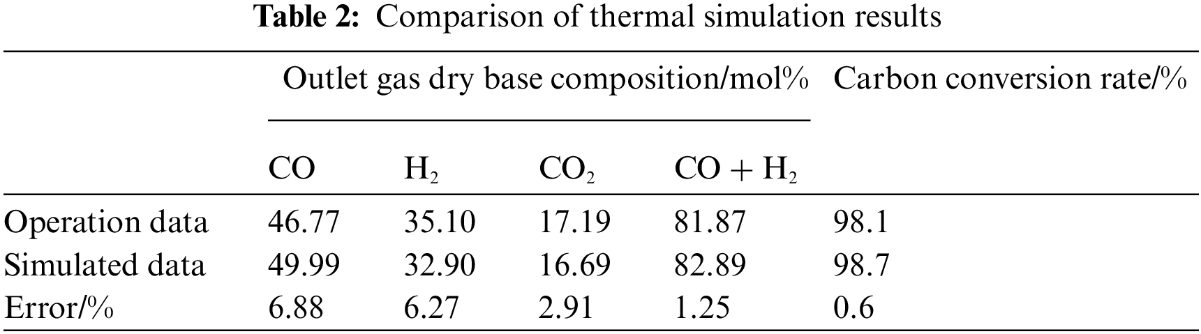
As shown in Table 2, the simulation results were compared with the industrial data of the four-nozzle gasifier, and the errors of all parameters were within 7%. It shows that the model is suitable for gasification of CWS within the error allowed range. This paper uses the numerical model to simulate the gasification of OBDC-CWS, and explores the gasification law after mixing OBDC.
3 Simulation Process and Result Analysis
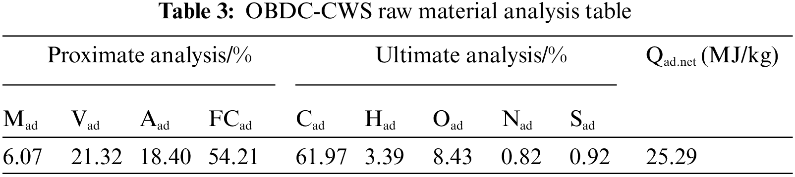
The CWS flow of the nozzle at the top of the gasifier is set at 300 kg/h, and the oxygen flow is set at 114 Nm3/h. The flow rate of the single nozzle on the side of the furnace is set to 75 kg/h, and the oxygen flow rate is set to 28.5 Nm3/h. The oxygen-carbon ratio (OCR) was 1.0, the concentration of OBDC-CWS was 62%, and the gasification pressure was 4.0 MPa. Proximate analysis and ultimate analysis of OBDC and pulverized coal mixtures are shown in Table 3.
The nozzle layout design of the gasifier has a decisive effect on the distribution of the flow field in the furnace [29]. The distribution of the flow field will directly affect the distribution of effective gas, particle trajectory, and temperature field in the furnace. When the concentration of OBDC-CWS is 62%, the velocity distribution of the combustion chamber is shown in Figs. 2a and 2b. The figure shows that the velocity field in the gasifier has an axisymmetric distribution. The fuel and oxidizer are shot into the gasification chamber at high speed from the nozzle to form five jets, with the flow rate of 57 m/s into the furnace. A high-speed jet zone is formed near the nozzle, while the five jets collide violently near the center of the gasifier, losing kinetic energy to form a low-speed zone. The turbulence intensity cloud diagram of the combustion chamber is shown in Fig. 2c. The intersection of five jets forms a strong mixing region with turbulence intensity as high as 300%–500%. In this region, the fluid and discrete phase particles have complex interaction effects and violent disturbances, making the particles have sufficient contact with the oxidizer. It greatly promotes the combustion and gasification reactions [30]. The closer the area is to the gasifier outlet, the more gentle the change of velocity. The velocity increases to a certain extent in the contraction section near the outlet, and the calculation shows that the outlet velocity reaches 1.6 m/s.
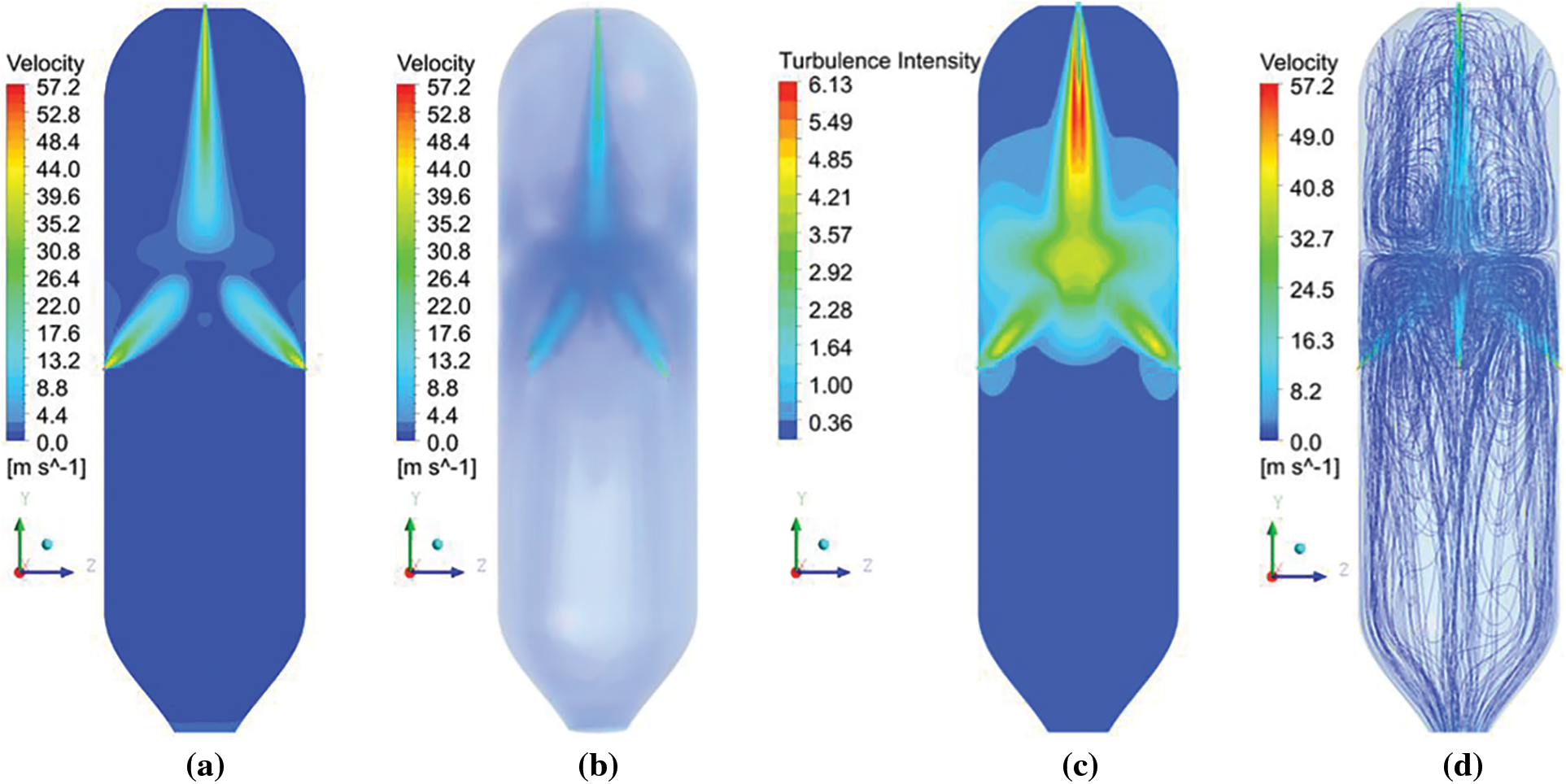
Figure 2: State contour of working medium in the combustion chamber. (a) Velocity contour, (b) 3D velocity contour, (c) Turbulence intensity contour, (d) Streamline diagram
Fig. 2d is the streamline diagram inside the combustion chamber. It can be seen from the diagram that four reflux regions are formed in the top region of the combustion chamber due to the uncoiling of the top nozzle and the impact of the secondary nozzle on the furnace side. In the central region, the collision of five jet streams and the entrainment effect of the auxiliary nozzle make the reflux situation in this region more complex. It can be seen from the streamline diagram that the reflux situation of the fluid in this region has obvious characteristics of short distance and high reflux frequency [31–33]. Combined with velocity cloud Fig. 2a, the analysis shows that the jet velocity of the top nozzle decreases significantly after passing through the impact area [34]. Therefore, the setting of the secondary nozzle plays an effective role in preventing short-circuiting of the top jet. Compared with the existing Texaco and four-nozzle opposed gasifiers, this furnace has obvious advantages in this aspect [35].
The internal temperature distribution in the combustion chamber is shown in Fig. 3, which is axisymmetric. In the area around the nozzle of oxygen is adequate, there is mainly intense combustion reaction and rapid consumption of oxygen to form the high-temperature fire. The heat is mainly from the volatile matter in coal particles and fixed carbon combustion reactions to emit large amounts of heat. The temperature is generally higher than 2300 K. The flame temperature in the area where the jet collision occurs is relatively low, around 2100 K. On the one hand, low oxygen content leads to reduced heat release from combustion reactions; on the other hand, due to insufficient oxygen at high temperatures, carbon gasification reactions occur, and part of the heat is absorbed. The temperature is relatively low in the area near the top nozzle and the pipe flow area under the combustion chamber, and the temperature in the area remains stable. Under the dual influence of gravity and top jet, the distribution of combustion particles in the top region is relatively small, and the total heat release of combustion particles is relatively low, which is the main reason for the lower temperature in this region.
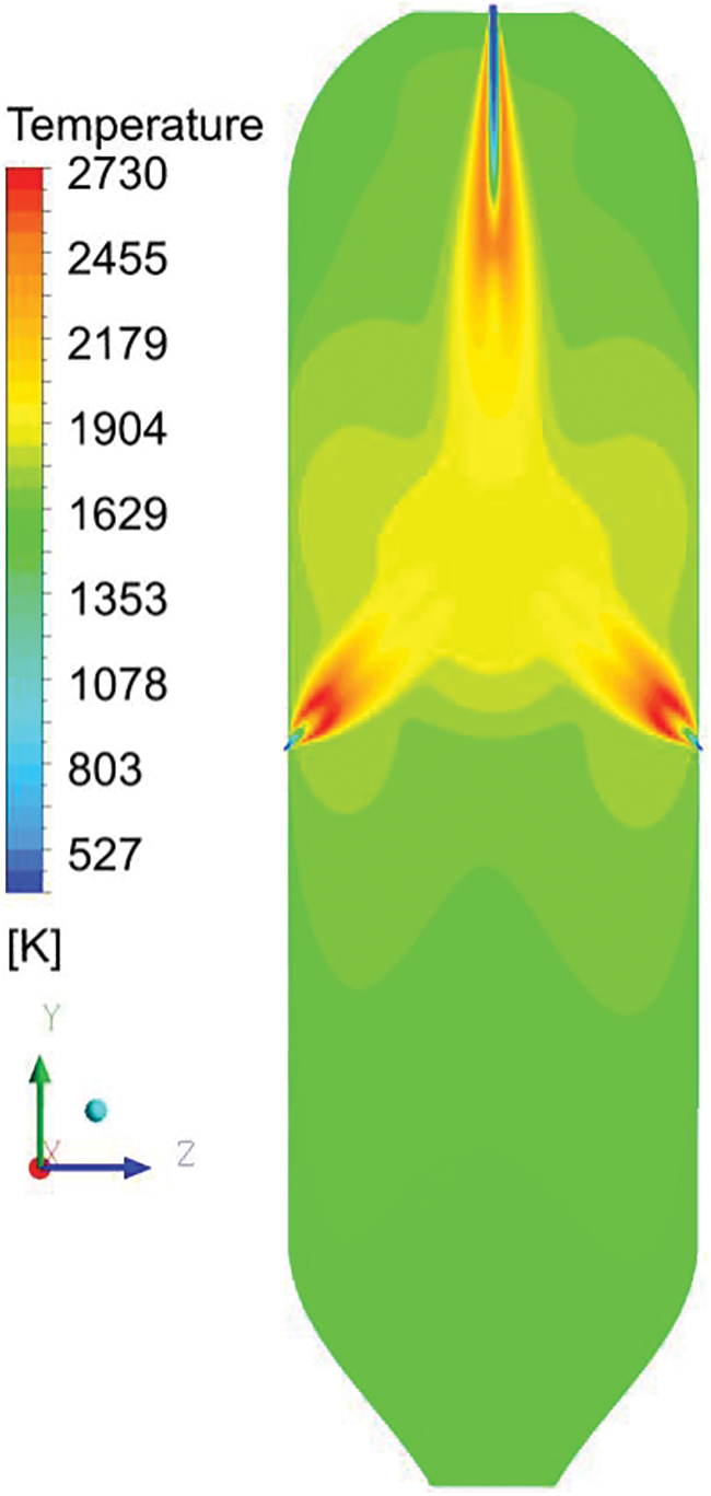
Figure 3: Temperature contour
From the cloud image comparison, it can be seen that the medium- and high-temperature regions above 2000 K overlap with the reflux region in Fig. 2d, indicating that the design scheme of main and secondary nozzle jet hedging could cut off the main nozzle jet, and the control reflux region was concentrated in the middle and upper part of the combustor.
The main gas products at the outlet of the combustion chamber are CO, CO2, H2 and H2O(g). The distribution of the gas mole fraction of each component is shown in Fig. 4. The cloud diagram of each component presents an axisymmetric distribution, and the distribution of gas products is closely related to the temperature distribution in the combustion chamber. As a result, the mole fraction of CO2 and H2O(g) is higher, while the mole fraction of CO and H2 is lower. In the low-temperature region due to hypoxia, carbon gasification reactions mainly occur, leading to an increase in the mole fraction of reducing gas products CO and H2. All kinds of gasification products are evenly distributed near the outlet, and the gasification reaction has reached an equilibrium state.
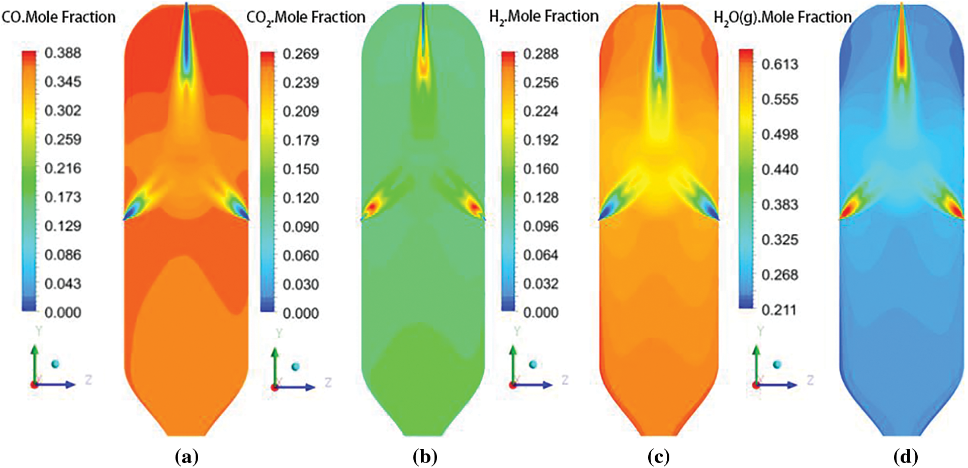
Figure 4: Gas distribution contour of CWS gasification
3.1 Influence of Concentration Change on Gasification Results
The concentration of OBDC-CWS is one of the most important indicators in the gasification process. In this section, the gasification results of CWS after the addition of 15% OBDC are studied. The effect of changing the concentration on gasification of OBDC is studied from the following two aspects: (1) The effect of fixed oxygen flow rate on gasification results was studied. (2) The effect of a fixed OCR of 1 on the gasification results was studied [36]. The OBDC-CWS concentrations used were 59%, 62%, 65%, 68%, and 71%, respectively.
3.1.1 Fixed Oxygen Flow Unchanged
Parameter setting: The OBDC-CWS flow rate from the top nozzle of the gasifier is 300 kg/h and the oxygen flow rate is 98.6 Nm3/h. The flow rate of the fireside single burner nozzle is 75 kg/h, the oxygen flow rate is 24.65 Nm3/h, and the gasification pressure is 4.0 MPa. The oxidizer flow rate in the gasifier was kept constant under the conditions of different OBDC-CWS concentrations. The calculated results are shown in Fig. 5.
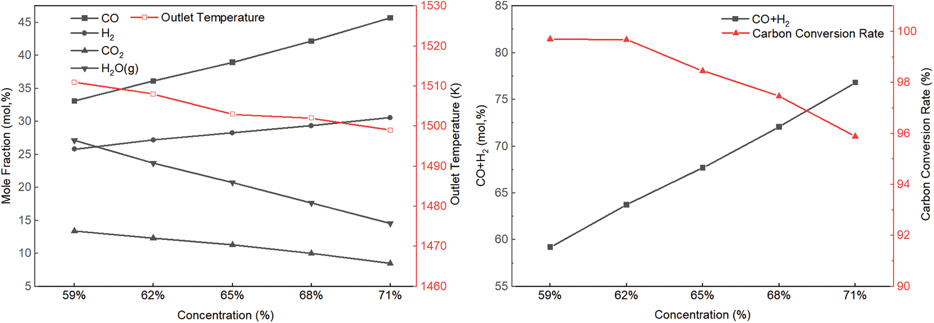
Figure 5: Variation of parameters at the outlet with concentration
As the OBDC-CWS concentration increases, the molar percentage of CO and H2 in the combustor outlet gas increases. The molar content of CO increased by 12.6% from 33.10% to 45.70%. And the molar content of H2 increased by 4.78%. The molar content of effective gas increased from 59.21% to 76.83%. However, the molar percentage of CO2 and H2O(g) decreased with increasing OBDC-CWS concentration. The carbon conversion rate also decreases as the OBDC-CWS concentration increases, especially when the concentration is greater than 62%.
The reason for this phenomenon is that as the concentration increases, the flow rate of dry coal into the gasifier increases, and the reaction intensity of coke with CO2 and H2O(g) increases. Due to the endothermic reaction
Parameter setting: The flow rate of OBDC-CWS from the top nozzle of the gasifier is 300 kg/h, the flow rate of the single nozzle on the side of the furnace is 75 kg/h, and the gasification pressure is 4.0 Mpa. The fixed OCR is 1, and the calculation results are shown in Fig. 6 under different OBDC-CWS concentrations.
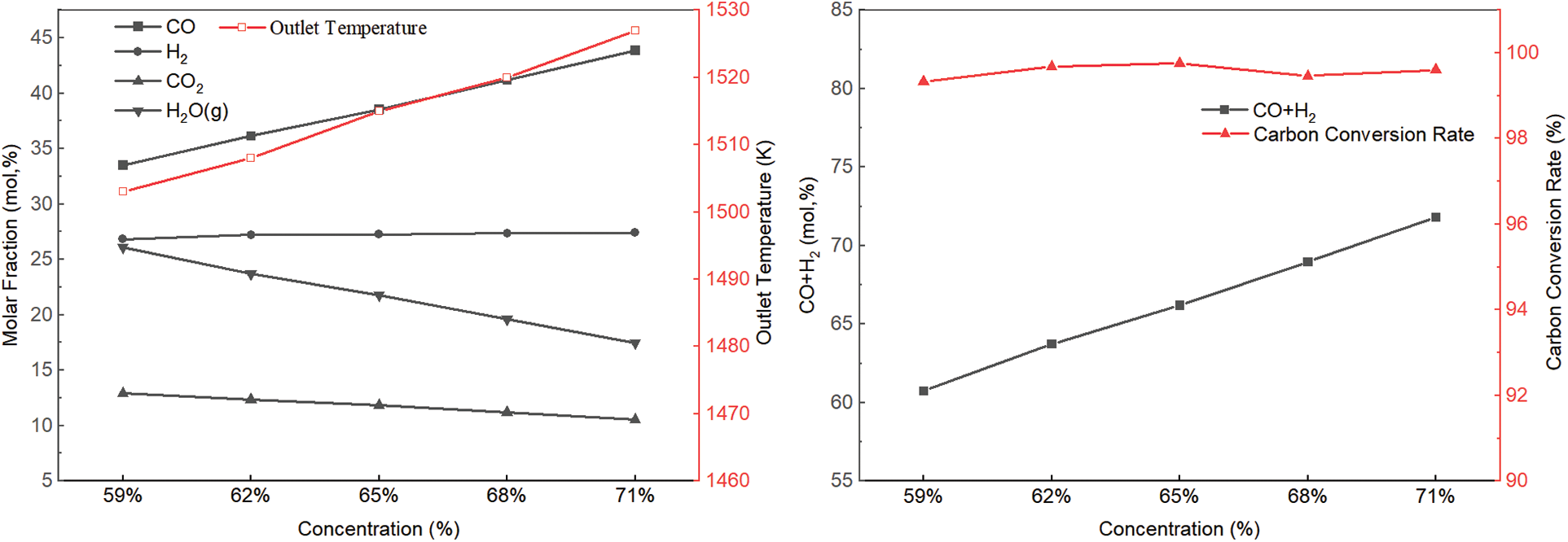
Figure 6: Variation of parameters at the outlet with concentration
As the OBDC-CWS concentration increases, the gas outlet temperature increases continuously. The mole percent of CO increased from 33.52% to 43.87%. The mole percent of H2 does not change much. The molar percentages of CO2 and H2O decreased from 12.91% and 26.10% to 10.54% and 17.47%, respectively. The effective gas molar content increased from 60.73% to 71.79%. The carbon conversion rate at various concentrations is greater than 99%, and the change in concentration has little effect on the carbon conversion rate. In the study by Chen et al. [37], the highest flame temperature reached 2719 K in the simulated gasification process of coal +20% sludge, and the molar percentage of CO + H2 in the export gas reached 82.7%.
The reason for this phenomenon is that when the OCR is 1, increasing the concentration of OBDC-CWS will increase the mass fraction of coal. Coke in the furnace mainly reacts
3.2 Influence of OCR Change on Gasification Results
The OCR refers to the molar ratio of oxygen atoms to carbon atoms in the raw material entering the furnace, which is an important factor affecting the gasification result [38]. To study the effect of OCR on the gasification results, the thermal simulation was carried out when the concentration of OBDC-CWS was 62% and the OCR was 0.92, 0.96, 1, 1.03, and 1.05, respectively.
As shown in Fig. 7, the OCR has a great influence on the temperature in the gasifier. As the OCR increases, the temperature increases from 1464 to 1519 K. The combustible component of the export gas showed a decreasing trend, while the molar content of CO2 and H2O increased continuously. The molar content of effective gas decreased from 65.37 to 61.73. As the OCR increases, the carbon conversion rate also increases, but when the OCR is less than 1, the carbon conversion rate increases faster. When the OCR is greater than 1, the carbon conversion rate fluctuates around 99.70%.
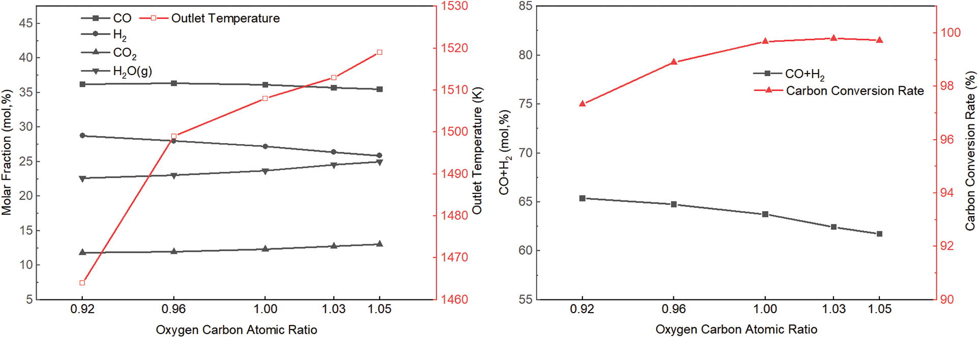
Figure 7: The variation of parameters at the outlet with OCR
This occurs because the gasification atmosphere in the furnace is altered by the change in the OCR. If the OCR is less than 1, the furnace is in a state of anoxia and part of the coke cannot be completely oxidized. Therefore, the temperature in the furnace is low, and the carbon conversion rate is not high. When the OCR is greater than 1, the furnace is in an oxygen-rich state, the coke can be completely oxidized and release a lot of heat, causing the temperature in the furnace to rise. The excess oxygen partially burns the combustible components, thus increasing the molar content of CO2 and H2O.
The appropriate OCR can not only improve the carbon conversion rate of the whole gasifier, but also improve the production efficiency [39,40]. Therefore, it is necessary to strictly control the ratio of fuel and oxidizer in the furnace during production. In Yuan’s study [41], when the concentration of CWS is increased in the range of 64% to 68%, the average temperature in the furnace increases and the effective gas mole fraction at the outlet increases. The increasing OCR in the range of 1.11~1.17 leads to the decrease of effective gas content at export.
3.3 Influence of Different Working Conditions on the Calorific Value of Gas
The effect of different concentrations and the OCR on the calorific value of gas is shown in Fig. 8. Curves 1, 2, and 3 in the figure correspond to the simulation results when the fixed oxygen flow rate remains unchanged, the fixed OCR remains unchanged, and the ratio of OCR changes. The comparison shows that the heating value increases faster with concentration when the oxygen flow is fixed. However, the calorific value of OCR = 1 is higher when the concentration is less than 62%. The reason may be that when the concentration is low, there are more oxygen atoms than carbon atoms in the fixed amount of oxygen, resulting in more CO2 being produced in the gasification process and a decrease in calorific value. As the OCR increases, the calorific value of the gas gradually decreases because the increase in oxygen content causes a decrease in the combustible components of the gas composition.
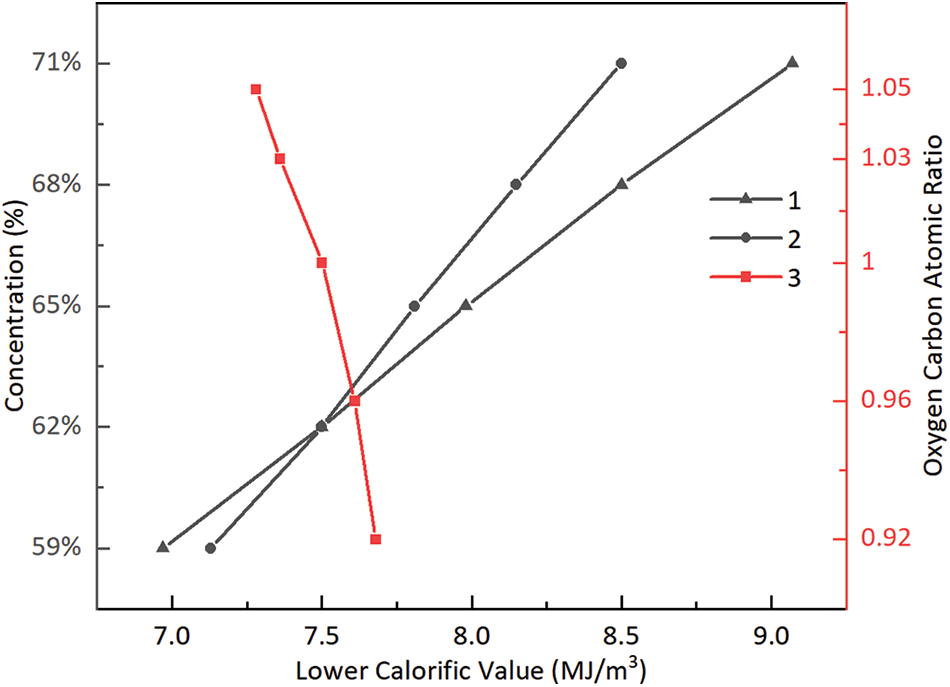
Figure 8: Influence of different conditions on calorific value of gas
3.4 Comparison with Ordinary CWS Gasification
In order to compare the gasification effect of OBDC-CWS and ordinary CWS, the calculation results of OBDC-CWS and ordinary CWS were compared and analyzed. The compared working conditions are as follows: The dip angle of the furnace side nozzle is 45°, the OCR is 1, the coal slurry concentration is 62%, the coal slurry flow rate of the furnace top nozzle is 300 kg/h, the flow rate of the furnace side single nozzle is 75 kg/h, and the gasification pressure is 4.0 MPa. The oxygen consumption of ordinary CWS gasification is 227.23 Nm3/h, and that of OBDC-CWS is 197.15 Nm3/h. Compared with the conventional CWS, the OBDC-CWS can save 13.24% oxygen per hour. The comparative results are shown in Table 4.
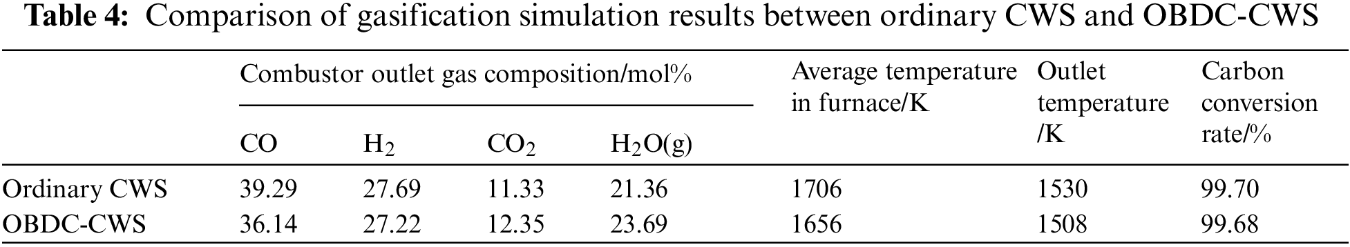
Compared with the results of ordinary CWS gasification, except for some differences in the composition of the synthesis gas, the other results are basically not much different, indicating that the addition of a reasonable amount of OBDC does not have a large negative impact on the results of CWS gasification.
It is a new way to treat OBDC by using CWS cooperatively. The results of gasification are analyzed by numerical simulation, and the following conclusions are drawn:
(1) Under the condition of a fixed oxygen flow rate, the molar content of effective gas increases with increasing concentration, but the carbon conversion rate decreases continuously.
(2) When the fixed OCR is 1, the molar content of effective gas still increases with increasing concentration, while the carbon conversion rate does not change much.
(3) The change of the OCR has a great effect on the gasification results. When the OCR is less than 1, the carbon conversion rate increases with the increase of the OCR, while when the OCR is greater than 1, the carbon conversion rate is stable at about 99.70%.
(4) The calorific value of gas varies greatly under different gasification conditions. With the increase of concentration, the calorific value of gas increases rapidly under the condition of constant oxygen flow.
(5) Compared with the gasification results of ordinary CWS, the numerical simulation results of CWS with 15% of OBDC did not change significantly.
Funding Statement: This research was funded by the Postgraduate Research & Practice Innovation Program of Jiangsu Province, China (KYCX21_2815).
Conflicts of Interest: The authors declare that they have no conflicts of interest to report regarding the present study.
References
1. Zhang, M. L., Cai, H. Y., Zhou, Q. (2018). Chongqing carries out research on pollution control of solid waste from shale gas exploitation. Renewable Resources, 11, 42–44. [Google Scholar]
2. Zhou, H., Wang, G. B., Li, M., Zhang, L., Chen, S. Y. et al. (2017). Pyrolysis characteristics of oil-bearing drill cuttings. Journal of Environmental Engineering, 11(12), 6421–6428. [Google Scholar]
3. Perez, P. A., Reuben, N. O., Josiah, M. A. (2019). Diagnostic screening of organic contaminant level in solidified/stabilized pre-treated oil-based drill cuttings. Heliyon, 5(10), e02644. https://doi.org/10.1016/j.heliyon.2019.e02644 [Google Scholar] [PubMed] [CrossRef]
4. Yang, M., Chen, X. L., Zhao, J. F., Li, W. C. (2021). Research on the treatment and resource utilization of oil and gas development and drilling waste. New Building Materials, 48(12), 155–161. [Google Scholar]
5. Chen, Z., Li, D. Y., Chen, H. Z., Chen, Q., Xu, F. L. et al. (2019). New progress in treatment and disposal of oil-based drilling cuttings. Chemical Industry and Environmental Protection, 39(5), 489–495. [Google Scholar]
6. Jiang, Y., Zhao, Z. C., Zhao, D. F. (2005). Characteristics and treatment of oily sludge. Environmental Protection of Oil and Gas Fields, 4, 42–45+64. [Google Scholar]
7. Tang, L., Huang, H. T., Hao, H. Q., Zhao, M. M. (2015). Research progress in plasma pyrolysis/gasification system of solid waste. Science & Technology Review, 33(5), 109–114. [Google Scholar]
8. Wang, M. L., Zhang, H., Zhang, L., Wang, Y., Wang, W. et al. (2018). Acoustic-chemical combined cleaning of oil-bearing drill cuttings. Chemical Industry and Protection, 38(2), 222–226. [Google Scholar]
9. Ma, J., Yang, Y. Q., Dai, X. L., Chen, Y. T., Deng, H. M. et al. (2016). Effects of adding bulking agent, inorganic nutrient and microbial inocula on biopile treatment for oil-field drilling waste. Chemosphere, 150, 17–23. https://doi.org/10.1016/j.chemosphere.2016.01.123 [Google Scholar] [PubMed] [CrossRef]
10. Li, X. Q., Yang, J. R., Yin, Z. L. (2013). Research and development of new technology for harmless treatment of drilling fluid waste. Petroleum and Natural Gas Chemicals, 42(4), 439–442. [Google Scholar]
11. Liu, X., Zhou, Z. J., Wang, F. C. (2014). The effect of industry slag on coal water slurry and gasification. Energy Sources, Part A: Recovery, Utilization, and Environmental Effects, 36(17), 1871–1876. https://doi.org/10.1080/15567036.2011.596905 [Google Scholar] [CrossRef]
12. Yang, D. Y., Hu, G. F., Qi, Y. H., Wang, Y. (2017). Numerical simulation of gasification of sewage sludge mixed with coal water slurry. Natural Gas Chemistry, 42(3), 23–27. [Google Scholar]
13. Sun, Z. H., Dai, Z. H., Zhou, Z. J., Xu, J. L., Yu, G. S. (2012). Comparative study of gasification performance between bituminous coal and petroleum coke in the industrial opposed multiburner entrained flow gasifier. Energy & Fuels, 26, 6793–6802. https://doi.org/10.1021/ef301189c [Google Scholar] [CrossRef]
14. Mansur, F. Z., Faizal, C., Samad, N., Atnaw, S. M., Sulaiman, S. A. (2020). Gasification performance of sawdust, pelletized sawdust and sub-bituminous coal in a downdraft gasifier. SN Applied Sciences, 2(9), 441–450. https://doi.org/10.1007/s42452-020-03358-x [Google Scholar] [CrossRef]
15. Donskoy, I. G. (2019). Influence of coal-biomass fuel composition on the efficiency of its conversion in entrained-flow gasifiers. Solid Fuel Chemistry, 53(2), 113–119. https://doi.org/10.3103/S0361521919020046 [Google Scholar] [CrossRef]
16. Zhang, H. (2009). Nature, harm and treatment of dioxins. Chinese Chlor-Alkali, 10, 16–18. [Google Scholar]
17. Choi, Y. C., Li, X. Y., Park, T. J., Kim, J. H., Lee, J. G. (2001). Numerical study on the coal gasification characteristics in an entrained flow coal gasifier. Fuel, 80(15), 2193–2201. https://doi.org/10.1016/S0016-2361(01)00101-6 [Google Scholar] [CrossRef]
18. Yu, H. L., Zhao, X., Zhou, Z. J., Zhou, J. H., Liu, J. Z. (2005). Numerical simulation of influence of coal slurry concentration on gasification of coal water slurry. Power Engineering, 25(2), 217–220. [Google Scholar]
19. Watanabe, H., Otaka, M. (2006). Numerical simulation of coal gasification in entrained flow coal gasifier. Fuel, 85(21), 1935–1943. https://doi.org/10.1016/j.fuel.2006.02.002 [Google Scholar] [CrossRef]
20. Guo, Q. H., Zhou, Z. J., Wang, F. C., Yu, G. S. (2014). Slag properties of blending coal in an industrial OMB coal water slurry entrained-flow gasifier. Energy Conversion and Management, 86, 683–688. https://doi.org/10.1016/j.enconman.2014.06.054 [Google Scholar] [CrossRef]
21. Lv, Q. W., Wang, L. A., Ma, S. D., Jiang, J. J., Liu, L. Y. et al. (2022). Pyrolysis of oil-based drill cuttings from shale gas field: Kinetic, thermodynamic, and product properties. Fuel, 323, 1–11. https://doi.org/10.1016/j.fuel.2022.124332 [Google Scholar] [CrossRef]
22. Christian, H., Paulo, D., Xu, W., Klaus, H., Michele, V. et al. (2021). Advanced modeling approaches for CFD simulations of coal combustion and gasification. Progress in Energy and Combustion Science, 86, 100938. https://doi.org/10.1016/j.pecs.2021.100938 [Google Scholar] [CrossRef]
23. Yu, H. L., Wang, F. K., Zhang, G. F., Liu, J. Z. (2012). Numerical simulation of coal oil water slurry gasification process in new-type coal water slurry gasifier. Applied Mechanics and Materials, 2034, 2501–2505. https://doi.org/10.4028/www.scientific.net/AMM.229-231.2501 [Google Scholar] [CrossRef]
24. Tiwary, S., Ghugare, S. B., Chavan, P. D., Saha, S., Datta, S. et al. (2020). Co-gasification of high ash coal-biomass blends in a fluidized bed gasifier: Experimental study and computational intelligence-based modeling. Waste and Biomass Valorization, 11(2), 323–341. https://doi.org/10.1007/s12649-018-0378-7 [Google Scholar] [CrossRef]
25. Chen, C. X., Horio, M., Kojima, T. (2001). Use of numerical modeling in the design and scale-up of entrained flow coal gasifiers. Fuel, 80(10), 1513–1523. https://doi.org/10.1016/S0016-2361(01)00013-8 [Google Scholar] [CrossRef]
26. Che, D. Y., Li, S. H., Yang, W. G., Jia, J., Zheng, N. (2012). Application of numerical simulation on biomass gasification. Energy Procedia, 17, 49–54. https://doi.org/10.1016/j.egypro.2012.02.061 [Google Scholar] [CrossRef]
27. Feng, P., Lin, W. G., Jensen, P. A., Song, W. L., Hao, L. F. et al. (2016). Entrained flow gasification of coal/bio-oil slurries. Energy, 111, 793–802. https://doi.org/10.1016/j.energy.2016.05.115 [Google Scholar] [CrossRef]
28. Sun, Z. H., Dai, Z. H., Zhou, Z. J. (2012). Numerical simulation of industrial opposed multiburner coal-water slurry entrained flow gasifier. Industrial & Engineering Chemistry Research, 51(6), 2560–2569. https://doi.org/10.1021/ie201542q [Google Scholar] [CrossRef]
29. Liu, J. G., Jiang, X. M., Zhou, L. S., Wang, H., Han, X. X. (2009). Co-firing of oil sludge with coal-water slurry in an industrial internal circulating fluidized bed boiler. Journal of Hazardous Materials, 167(1), 817–823. https://doi.org/10.1016/j.jhazmat.2009.01.061 [Google Scholar] [PubMed] [CrossRef]
30. Wu, X. X., Guo, Q. H., Gong, Y., Liu, J. Y., Luo, X. et al. (2022). Influence of burner geometry on atomization of coal water slurry in an entrained-flow gasifier. Chemical Engineering Science, 247, 117088. https://doi.org/10.1016/j.ces.2021.117088 [Google Scholar] [CrossRef]
31. Chen, C. J., Hung, C. I., Chen, W. H. (2012). Numerical investigation on performance of coal gasification under various injection patterns in an entrained flow gasifier. Applied Energy, 100, 218–228. https://doi.org/10.1016/j.apenergy.2012.05.013 [Google Scholar] [CrossRef]
32. Bi, D. P., Guan, Q. L., Xuan, W. W., Zhang, J. S. (2015). Numerical simulation of GSP gasifier under different swirl angles. Fuel, 155, 155–163. https://doi.org/10.1016/j.fuel.2015.04.001 [Google Scholar] [CrossRef]
33. Zhong, H. B., Lan, X. Y., Gao, J. S. (2015). Numerical simulation of pitch-water slurry gasification in both downdraft single-nozzle and opposed multi-nozzle entrained-flow gasifiers: A comparative study. Journal of Industrial and Engineering Chemistry, 27, 182–191. https://doi.org/10.1016/j.jiec.2014.12.033 [Google Scholar] [CrossRef]
34. Cao, C. W., Zhang, Y. K., Yu, T., Gu, X. S., Xin, Z. et al. (2015). A novel 3-layer mixed cultural evolutionary optimization framework for optimal operation of syngas production in a Texaco coal-water slurry gasifier. Chinese Journal of Chemical Engineering, 23(9), 1484–1501. https://doi.org/10.1016/j.cjche.2015.03.005 [Google Scholar] [CrossRef]
35. Guo, Q. H., Zhang, Z. Q., Xue, Z. C., Gong, Y., Yu, G. S. et al. (2019). Coal char particle secondary fragmentation in an entrained-flow coal-water slurry gasifier. Journal of the Energy Institute, 92(3), 578–586. https://doi.org/10.1016/j.joei.2018.04.001 [Google Scholar] [CrossRef]
36. Li, C., Dai, Z. H., Sun, Z. H. (2013). Modeling of an opposed multiburner gasifier with a reduced-order model. Industrial & Engineering Chemistry Research, 52(16), 5825–5834. https://doi.org/10.1021/ie3030505 [Google Scholar] [CrossRef]
37. Chen, Y. G., Zhang, W. Q., Wang, Y. F., Zhu, Y. Z. (2021). Numerical simulation of high temperature gasification characteristics of coal-mixed oily sludge. Energy Research and Utilization, 3, 44–49. https://doi.org/10.3969/j.issn.1001-5523.2021.03.008 [Google Scholar] [CrossRef]
38. Jeong, H. J., Hwang, I. S., Park, S. S., Hwang, J. (2017). Investigation on co-gasification of coal and biomass in Shell gasifier by using a validated gasification model. Fuel, 196, 371–377. https://doi.org/10.1016/j.fuel.2017.01.103 [Google Scholar] [CrossRef]
39. Wang, L. J., Du, X. C., Chen, J. Q., Wu, Z. G. (2021). Numerical study on characteristics of biomass oxygen enriched gasification in the new gasifier on an experimental basis. Renewable Energy, 179, 815–827. https://doi.org/10.1016/j.renene.2021.07.098 [Google Scholar] [CrossRef]
40. Hwang, I. S., Sohn, J., Lee, U. D., Hwang, J. (2021). CFD-DEM simulation of air-blown gasification of biomass in a bubbling fluidized bed gasifier: Effects of equivalence ratio and fluidization number. Energy, 219, 119533. https://doi.org/10.1016/j.energy.2020.119533 [Google Scholar] [CrossRef]
41. Yuan, D. D. (2016). Numerical simulation and analysis of gasification process in coal water slurry gasifier (Master Thesis). Materials Science and Engineering, Wuhan University of Science and Technology, China. [Google Scholar]
Cite This Article
 Copyright © 2023 The Author(s). Published by Tech Science Press.
This work is licensed under a Creative Commons Attribution 4.0 International License , which permits unrestricted use, distribution, and reproduction in any medium, provided the original work is properly cited.
 Downloads
 Citation Tools