
 Submit a Paper
 Propose a Special lssue
 Open Access
ARTICLE
Research on Reactive Power Optimization of Offshore Wind Farms Based on Improved Particle Swarm Optimization
1 State Grid Jiangsu Nantong Electric Power Co., Ltd., Nantong, 226000, China
2 College of Energy and Electrical Engineering, Hohai University, Nanjing, 211100, China
* Corresponding Author: Lichengzi Yu. Email:
Energy Engineering 2023, 120(9), 2013-2027. https://doi.org/10.32604/ee.2023.028859
Received 11 January 2023; Accepted 06 April 2023; Issue published 03 August 2023
 View Full Text
 Download PDF
Abstract
The lack of reactive power in offshore wind farms will affect the voltage stability and power transmission quality of wind farms. To improve the voltage stability and reactive power economy of wind farms, the improved particle swarm optimization is used to optimize the reactive power planning in wind farms. First, the power flow of offshore wind farms is modeled, analyzed and calculated. To improve the global search ability and local optimization ability of particle swarm optimization, the improved particle swarm optimization adopts the adaptive inertia weight and asynchronous learning factor. Taking the minimum active power loss of the offshore wind farms as the objective function, the installation location of the reactive power compensation device is compared according to the node voltage amplitude and the actual engineering needs. Finally, a reactive power optimization model based on Static Var Compensator is established in MATLAB to consider the optimal compensation capacity, network loss, convergence speed and voltage amplitude enhancement effect of SVC. Comparing the compensation methods in several different locations, the compensation scheme with the best reactive power optimization effect is determined. Meanwhile, the optimization results of the standard particle swarm optimization and the improved particle swarm optimization are compared to verify the superiority of the proposed improved algorithm.Keywords
It is the only path to achieve China’s carbon peaking and carbon neutrality goals and an important support for promoting green and low-carbon development [1] to promote the energy production and consumption revolution and build a clean, low-carbon, safe and efficient energy system and a new power system with new energy as the main body [2]. As an important part of new energy power generation, offshore wind power generation has a wide range of application prospects. In the planning and construction of offshore wind farms, due to the influence of long-distance cables, transformers, and generators [3,4], there might be insufficient reactive power [5,6] in the wind farm. To obtain the minimum construction cost and the maximum economic benefits, it is necessary to optimize the reactive power inside wind farms [7,8].
Literature [9] used the radial structure of wind farms to optimize the reactive power distribution of wind turbines, but the optimization strategy is only applicable for linearized systems. Literature [10] proposed to adopt the optimal diversion strategy for the stator and grid-side converter diversion, which minimizes the total loss of the wind power generation system. But the control method is relatively complex. Literature [11] proposed to use the external reactive power compensation device to compensate the system reactive power and optimize the capacity of the reactive power compensation device, but the algorithm convergence is poor. Literature [12] took the optimal compensation capacity and the node minimum voltage deviation as the objective function and uses the improved genetic algorithm for multi-objective optimization, but the programming is relatively complicated. Literature [13–15] took the power system connected to wind farms as the research object without considering the reactive power optimization within wind farms. In literature [16], the improved particle swarm optimization algorithm was used to optimize the reactive power of wind turbine output, but only the improvement of inertia weight is considered, and the ideal optimization effect cannot be achieved in the case of large reactive power deficit due to the generator output limitation.
To improve the voltage stability and reactive power economy of wind farm operating and address the local optimum and poor convergence effect of the traditional particle swarm optimization, this paper proposes an internal reactive power optimization scheme in wind farms based on the improved particle swarm optimization. First, the inertial weight and acceleration factor are optimized. Then, taking the minimum active power network loss in wind farms as the target function and considering the influencing factors of the node voltage deviation, power flow constraints, and inequality constraints, the optimal compensation capacity and compensation site for the external reactive power compensation device are determined and the reactive power compensation scheme with optimal economy is obtained. Finally, based on the example analysis of the actual data from a wind farm in Jiangsu Province, the feasibility and accuracy of the proposed improved particle swarm optimization are verified.
2 Internal Reactive Power Optimization Model of Wind Farms
2.1 Internal Power Flow Analysis of Offshore Wind Farms
Fig. 1 is the connection schematic diagram of an offshore wind farm in Jiangsu. The wind farm consists of 32 permanent magnet direct drive wind turbines, which can be divided into 6 groups according to the geographical location and connection mode. As shown in the G1-G6 of Fig. 1, each wind turbine is boosted to 35 kV by box-type transformer, connected to low voltage side of the main transformer (Node 33) through the 35 kV cable line, and into the wind farm grid through the 220 kV cable.
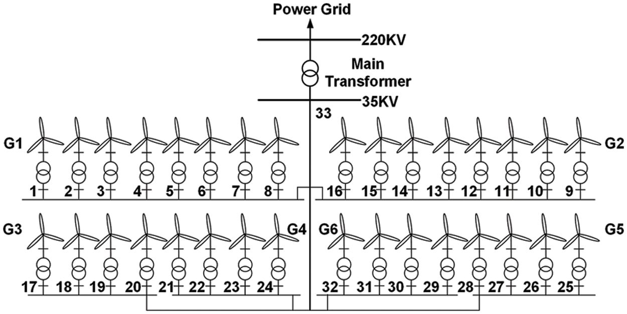
Figure 1: Connection schematic diagram of the offshore wind farm
The 35 kV cable line parameters in the wind farm are shown in Table 1. Due to different lengths and cross section areas of the cable connected to the fan, the connector impedance between nodes has certain differences, which constitute the transmission system in the wind farm.

According to the connection diagram of the offshore wind farm in Fig. 1 and the cable line parameters in Table 1, the power flow in the wind farm can be calculated. The calculation formula [17] of the wind farm in polar form is:
In the formula, Pi and Qi are the active and reactive power injected at node i; Gij and Bij are the branch conductance and susceptance between nodes i and j; Ui is the voltage at node i; θij is the phase angle difference between nodes i and j; and n is the number of nodes.
The unbalance equation of active and reactive power is obtained by calculating PQ node and PV node:
In the formula, △Pi and △Qi are the active and reactive unbalance of node i. Pis and Qis represent active power and reactive power injected by nodes, respectively.
The expression of Newton Raphson method modified equation in polar form is:
In the formula (3), the expressions of Jacobian matrix are:
According to formulas (3) and (4), the power correction amount and voltage correction amount after each iteration can be calculated. Then the correction amount and the initial amount are added to obtain the power component and voltage component of the next iteration. The internal power flow calculation flow chart of the offshore wind farm is shown in Fig. 2. The convergence condition of particle swarm optimization algorithm is that the minimum error is less than 0.15. Due to the fast convergence speed of the model. In order to facilitate the comparison of model operation results, the maximum iteration number of the algorithm is used as the judgment condition for algorithm termination, and the maximum iteration number is set to 50.
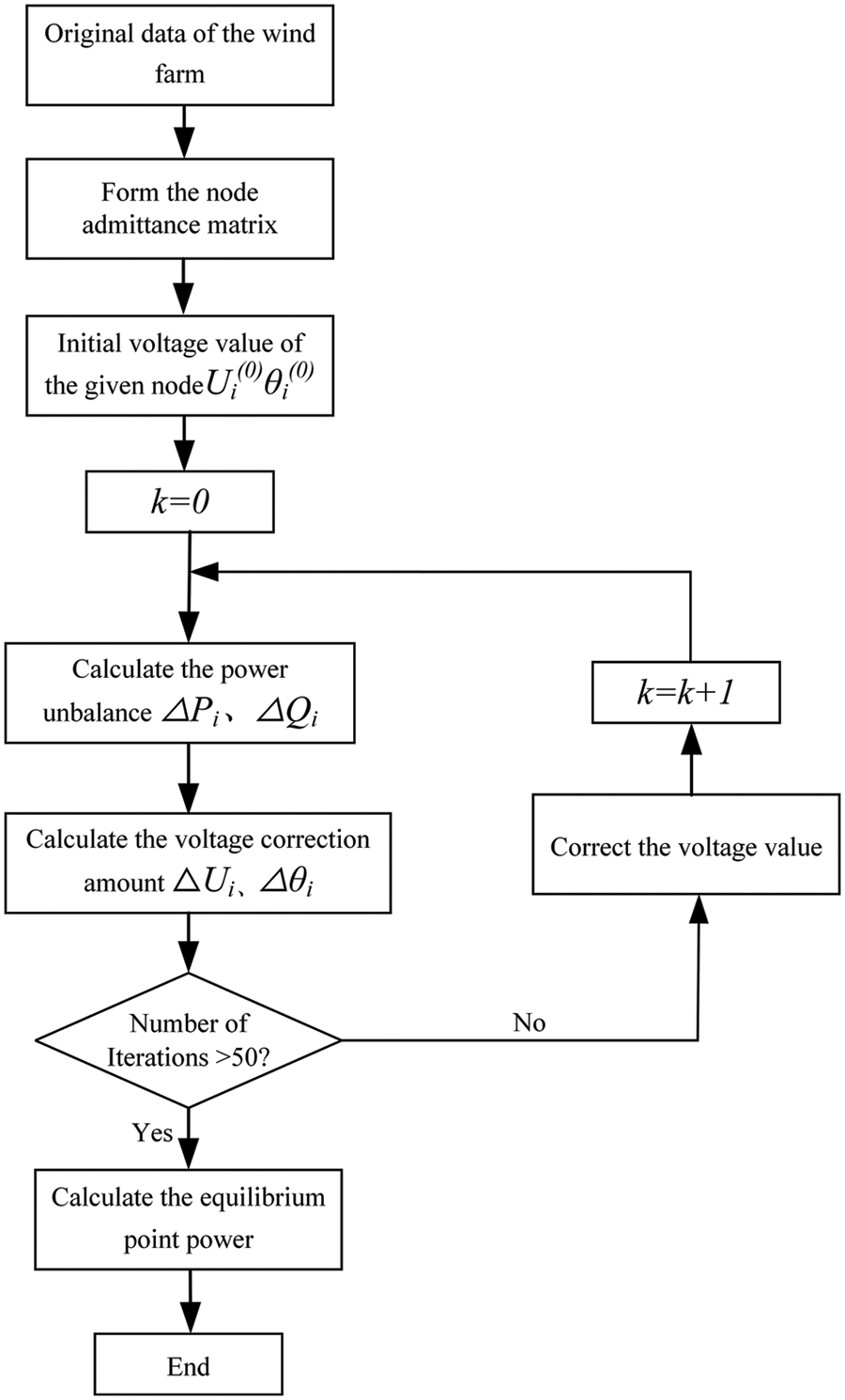
Figure 2: Power flow calculation flow chart of the offshore wind farm
2.2 Reactive Power Optimization Objective Function and Constraints
With the minimum internal network loss of the offshore wind farm as the objective function, the line loss of the wind farm is reduced by reactive power optimization and the reactive power economy in the wind farm is improved. To address the node voltage out-of-limit, the penalty function is added to the objective function. The objective function is expressed as follows:
In the formula, fpenalty is a penalty function and the specific expression is:
In the formula, k is the penalty function coefficient (k = 1 in the subsequent simulation); Uimax and Uimin are the maximum and minimum voltage values of node i; and the value selection of △Ui is shown in formula (7):
On the basis of determining the reactive power optimization objective function, it is necessary to analyze the constraints in the offshore wind farm wherein the equality constraint is the wind farm power flow constraint as shown in formula (8):
In the formula, PGi and PLi are the generator active output and node active load, respectively; and QGi, Qci, and QLi are the generator reactive output, compensated reactive power, and node reactive load, respectively.
The system inequality constraints can be divided into the generator output constraint, node voltage constraint, and reactive power compensation device capacity constraint with. The expression is as follows:
In the formula, QGimax and QGimin are the upper and lower limits of the generator reactive output; Qcimax and Qcimin are the upper and lower limits of compensation capacity of reactive power compensation device; and Uimax and Uimin are the upper and lower limits of node voltage. In the simulation experiment, the maximum and minimum values of node voltage are set as uimax = 1.13 and uimin = 0.96.
3 Reactive Power Optimization of Wind Farms Based on Improved Particle Swarm Optimization
3.1 Standard Particle Swarm Optimization
The standard particle swarm optimization is an algorithm which simulates the behavior of a flock of birds searching for food [18,19]. The position of each particle can be seen as a feasible solution in the problem space, and the state of the particle is described by the position vector and the velocity vector [20].
The particle swarm optimization first sets the position and flight speed of the particle in the search space as:
In the formula, i is the ith particle in the particle swarm; Xi is the position of the ith particle in the search space; Vi is the flight speed of the ith particle; D is the dimension of the search space; and N is the number of particles in the search space.
During the iteration, the particles continuously update [21] according to the individual optimal value Pbest and the global optimal value Gbest, expressed as:
In the formula, Pbest is the individual optimal value of the particle, and Gbest is the global optimal value.
To determine whether the convergence condition is reached, if the convergence condition is met, the optimization ends; if the target function does not converge, the particle position, velocity, and inertia factor need to be updated. The particle update formula is as follows:
In the formula, where l is the number of iterations; ω is the inertia weight; c1 and c2 are the learning factors; r1 and r2 are the random numbers between [0,1]; viD(l) and xiD(l) are the velocity and position of the the ith particle in the lth iteration; PbestiD(l) and QbestiD(l) are the individual optimal value and global optimal value in the lth iteration.
3.2 Improved Particle Swarm Optimization
In the standard particle swarm optimization, whether the particle converges depends on its flight trajectory. Limited by the particle velocity, its search range may not cover the whole feasible solution space, which will lead to the weak convergence, local optimum, and premature convergence [22].
To obtain better convergence effect and optimization result, the standard particle swarm optimization is improved from the inertia weight and learning factor. The inertia weight affects the solution accuracy of the algorithm. The particle swarm optimization with adaptive weights uses the relatively large inertia weight in the early stage of solving, which is conducive to global search. During the search process, the inertia weight is adjusted according to the particle fitness to improve the local optimization ability of the algorithm. The adjustment formula is as follows:
In the formula, ωmax and ωmin are the maximum and minimum values of the inertial weight; and f, fmin and fave are the current, minimum, and average fitness of the particle, respectively.
The learning factor of the standard particle swarm usually takes c1 = c2 and is set as a constant, which does not consider the focus of the particle search process and needs to update the learning factor in the iterative process to obtain the best global and local search ability. The update formula of the asynchronous learning factor is as follows:
In the formula, c1start and c1end are the start and end values of the learning factor c1, respectively; c2start and c2end are the start and end values of the learning factor c2, respectively; k is the current number of iterations; and Tmax is the maximum number of iterations.
According to the power flow calculation model of the offshore wind farm and the improved particle swarm optimization, the reactive power optimization steps of the wind farm can be obtained as in Fig. 3.

Figure 3: Reactive power optimization flow chart of the offshore wind farm based on improved particle swarm optimization
First, the network parameters of the wind farm and initialize the improved particle swarm parameters are inputted and the power flow results of the wind farm is obtained according to the power flow calculation steps shown in Fig. 2 to determine whether the particle satisfies the constraints. If it does, the objective function value and the individual fitness of each particle are calculated, the inertia weight and the learning factor are updated, and the individual optimal value, global optimal value, and optimal fitness for each particle are obtained to determine whether the objective function meets the convergence requirements. If does, the reactive power optimization result is output. If not, parameters such as the particle velocity, position, inertia weight, and learning factors are updated for the next calculation until the convergence requirements are met.
4.1 Reactive Power Optimization Analysis of Offshore Wind Farms
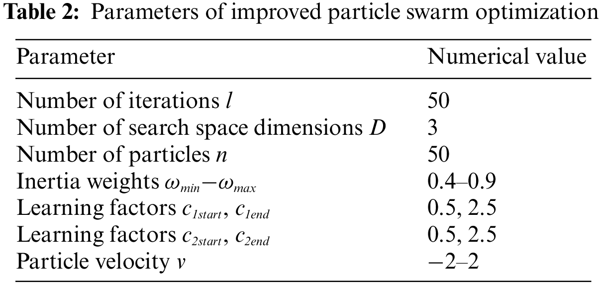
According to parameters of the wind farm architecture, fan, transformer, transmission system in Fig. 1 as well as the flow chart in Fig. 3, the wind farm reactive power optimization based on improved particle swarm optimization is programmed in MATLAB. The wind farm internal reactive power compensation device installation site and configuration capacity are optimized, the wind farm network loss and node voltage. According to the wind farm data shown in Fig. 1, the parameter Settings of the improved particle swarm optimization algorithm are shown in Table 2, and relevant parameters can be modified according to different application scenarios.
To simplify the algorithm, all the parameters of the wind farm are expressed with per unit values, where the capacity reference value is 100 MVA and the voltage reference value is 35 kV.
The voltage of each node in the offshore wind farm before adding the reactive power compensation device is shown in Table 3. Because of the existence of transmission cables, transformers, and generators, the voltage per unit value of some nodes is below 1. Therefore, reactive power compensation for the wind farm is needed to improve the voltage level of nodes.
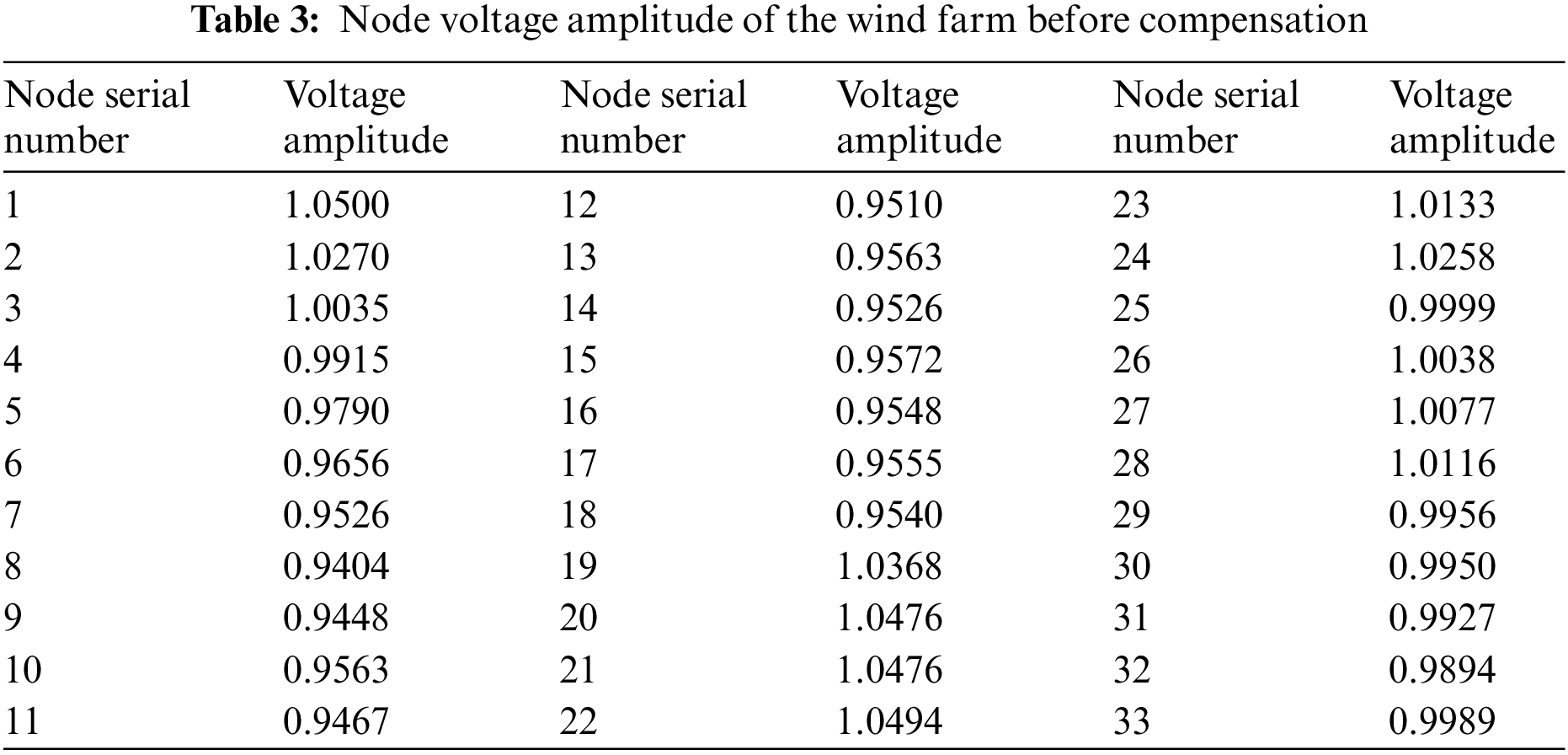
According to the actual project planning and construction needs, the Nodes 8, 11, 14, 18 and 32 can be compensated according to the comprehensive consideration of the weakness of the node voltage. Considering the construction cost and economic requirements, 3 of the above 5 nodes are selected as the installation points of the reactive power compensation device (SVC) with compensation mode A (Nodes 8, 11, and 14), compensation mode B (Nodes 8, 11, and 18), compensation mode C (Nodes 8, 11, and 32), compensation mode D (Nodes 8, 14, and 32), compensation mode E (Nodes 11, 18, and 32), and compensation mode F (Nodes 14, 18, and 32).
As shown in Table 4, the optimal reactive power compensation configuration capacity under the 6 reactive power compensation modes are compared. It can be seen that the total configuration capacity of the reactive power compensation device with compensation modes B and F is relatively small, 0.2286 and 0.2288, respectively, which can get the investment and installation cost of the optimal reactive power compensation device.

In addition to considering the investment cost of reactive power compensation device, the network loss cost of the wind farm also needs to be calculated. The wind farm network loss size before and after the compensation of the 4 compensation sites is shown in Table 5.

According to Table 5, compared with the initial network loss, compensation modes of 6 kinds of compensation sites can effectively reduce the network loss of the wind farm and realize the reactive power optimization. The network loss reduction rate with compensation modes D and F is 12.466% and 12.397%, respectively. The network loss cost is relatively low under these two compensation modes.
To further compare the advantages and disadvantages of each compensation mode, the convergence rate and node voltage amplitude increase of the optimization algorithm also need to consider. The target function iterative process diagram of the improved particle swarm optimization with 6 reactive power compensation modes are shown in Fig. 4. As can be seen, for these compensation modes, the convergence can be reached in 5 iterations and the convergence is fast.

Figure 4: Target function iterative process diagram of the improved particle swarm optimization
Fig. 5 shows the wind farm internal node voltage before and after optimization with different reactive power compensation modes. As can be seen from the figure, all the reactive power compensation modes can effectively improve the node voltage amplitude. But compensation modes D and F could increase the offshore wind farm internal node voltage amplitude more obviously, which are beneficial to improve the voltage stability of the wind farm.

Figure 5: Node voltage amplitude diagram of the wind farm before and after optimization
The installation capacity, wind farm network loss, algorithm convergence speed, and node voltage amplitude size of the reactive power compensation device are compared comprehensively. Compensation mode F is more economic in the device installation cost and network loss cost and meanwhile can achieve convergence after 4 iterations and have relatively good effects for the wind farm internal node voltage amplitude improvement. Compensation mode F can effectively improve the voltage stability of wind farms and has the best reactive power optimization effect.
4.2 Comparative Analysis before and after Particle Swarm Optimization
To verify the superiority of the improved particle swarm optimization proposed in Section 2.2, the reactive power optimization results of the standard particle swarm optimization and the improved particle swarm optimization are analyzed at the installation site (compensation mode F) of the optimal reactive power compensation device.
As shown in Table 6, the optimal compensation capacity and wind farm network loss size are obtained under the compensation mode F standard particle swarm optimization and improved the particle swarm optimization. Difference between the two in the optimal compensation capacity is only 0.0001. However, compared with the standard particle swarm optimization, the improved particle swarm optimization can reduce the network loss from 0.1283 to 0.1272, which effectively reduces the wind farm network loss and has better performance index in reactive power optimization results.

Fig. 6 is an iterative process diagram of the objective function for standard particle swarm optimization and improved particle swarm optimization. It can be seen that standard particle swarm optimization requires 25 iterations to reach a stable value, while improved particle swarm optimization only requires 4 iterations to reach a stable error value. Also it has faster algorithm iteration speed and lower network loss.

Figure 6: Comparison of objective functions before and after particle swarm optimization improvement
Fig. 7 shows the wind farm internal node voltage optimization results after using the standard particle swarm optimization and improved particle swarm optimization. Compared with the standard particle swarm optimization, the proposed improved particle swarm optimization can further improve the wind farm node voltage amplitude, is conducive to the voltage stability of offshore wind farms, and obtain better output power quality.

Figure 7: Figure of wind farm voltage optimization results before and after particle swarm optimization improvement
In conclusion, compared with the standard particle swarm optimization, the proposed improved particle swarm optimization has faster convergence speed, lower network loss, and higher node voltage amplitude in the reactive power optimization of actual offshore wind farms, which verifies the effectiveness and superiority of the improved particle swarm optimization.
In this paper, an internal reactive power optimization method for offshore wind farms based on an improved particle swarm optimization is proposed; the adaptive inertia weight and asynchronous learning factor are used to enhance the global search ability and local optimization ability of the particle swarm optimization. Based on the topology structure and network data of the actual offshore wind farm, the reactive power optimization model of the offshore wind farm is established by taking SVC compensation as an example and taking the minimum active power loss of the wind farm as the objective function in MATLAB. The selection of the compensation site takes into account the planning and construction requirements of the actual wind farm. The optimal compensation capacity, network loss size, algorithm convergence speed, and node voltage amplitude improvement degree are considered comprehensively to obtain the best compensation mode for reactive power optimization results. Meanwhile, the optimization results of the standard particle swarm optimization and the proposed improved particle swarm optimization are compared to prove the effectiveness and superiority of the improved particle swarm optimization.
Funding Statement: This work was supported by Technology Project of State Grid Jiangsu Electric Power Co., Ltd., China (J2022114, Risk Assessment and Coordinated Operation of Coastal Wind Power Multi-Point Pooling Access System under Extreme Weather).
Conflicts of Interest: The authors declare that they have no conflicts of interest to report regarding the present study.
References
1. Yao, G., Yang, H. M., Zhou, L. D., Li, D. D., Li, C. B. et al. (2021). Development status and key technologies of large capacity offshore wind turbine. Power System Automation, 45(21), 33–47. https://doi.org/10.7500/AEPS20210416003 [Google Scholar] [CrossRef]
2. Wang, Y. Z. (2021). The targets of carbon peak and carbon neutralization and China’s new energy revolution. Frontiers, 14, 88–96. https://doi.org/10.16619/j.cnki.rmltxsqy.2021.14.010 [Google Scholar] [CrossRef]
3. Xiang, X., Fan, S., Gu, Y., Ming, W., Wu, J. et al. (2021). Comparison of cost-effective distances for LFAC with HVAC and HVDC in their connections for offshore and remote onshore wind energy. CSEE Journal of Power and Energy Systems, 7(5), 954–975. https://doi.org/10.17775/CSEEJPES.2020.07000 [Google Scholar] [CrossRef]
4. Fu, Y., Liu, Y., Huang, L. L., Wei, S. R., Liu, L. J. (2018). Networking optimization of offshore wind farm cluster access system. Chinese Journal of Electrical Engineering, 38(12), 3441–3450+3. https://doi.org/10.13334/j.0258-8013.pcsee.171310 [Google Scholar] [CrossRef]
5. Ouyang, J., Li, M., Zhang, Z., Tang, T. (2019). Multi-timescale active and reactive power-coordinated control of large-scale wind integrated power system for severe wind speed fluctuation. IEEE Access, 7, 51201–51210. https://doi.org/10.1109/ACCESS.2019.2911587 [Google Scholar] [CrossRef]
6. Shen, Y. W., Liang, L. Q., Zhang, B., Liu, J. Y., Li, Y. (2020). Hierarchical coordinated optimal control strategy of wind farm based on improved sensitivity algorithm. Journal of Power System and Automation, 32(9), 28–33+41. https://doi.org/10.19635/j.cnki.csu-epsa.000403 [Google Scholar] [CrossRef]
7. Xu, B., Zhang, G., Li, K., Li, B., Chi, H. et al. (2022). Reactive power optimization of a distribution network with high-penetration of wind and solar renewable energy and electric vehicles. Protection and Control of Modern Power Systems, 7(1), 51. https://doi.org/10.1186/s41601-022-00271-w [Google Scholar] [CrossRef]
8. Laghridat, H., Essadki, A., Nasser, T. (2022). Coordinated control by ADRC strategy for a wind farm based on SCIG considering low voltage ride-through capability. Protection and Control of Modern Power Systems, 7(1), 7. https://doi.org/10.1186/s41601-022-00227-0 [Google Scholar] [CrossRef]
9. Jung, S., Jang, G. (2016). A loss minimization method on a reactive power supply process for wind farm. IEEE Transactions on Power Systems, 32(4), 3060–3068. https://doi.org/10.1109/TPWRS.2016.2621162 [Google Scholar] [CrossRef]
10. Zhang, B., Hou, P., Hu, W., Soltani, M., Chen, C. et al. (2016). A reactive power dispatch strategy with loss minimization for a DFIG-based wind farm. IEEE Transactions on Sustainable Energy, 7(3), 914–923. https://doi.org/10.1109/TSTE.2015.2509647 [Google Scholar] [CrossRef]
11. Zhang, Y. W., Sun, A. M., Zhang, Y. C., Li, Y. Z., Lin, Y. et al. (2011). Reactive power compensation capacity allocation and optimal operation of wind farm. Journal of Power System and Automation, 23(6), 150–156. https://doi.org/10.3969/j.issn.1003-8930.2011.06.029 [Google Scholar] [CrossRef]
12. Wu, X., Liu, T. Y., Jiang, X. C., Sheng, G. H. (2020). Reactive power optimization of offshore wind farm based on improved genetic algorithm. Electrical Measurement and Instrumentation, 57(4), 108–113. https://doi.org/10.19753/j.issn1001-1390.2020.04.017 [Google Scholar] [CrossRef]
13. Ding, T., Liu, S., Yuan, W., Bie, Z., Zeng, B. (2015). A two-stage robust reactive power optimization considering uncertain wind power integration in active distribution networks. IEEE Transactions on Sustainable Energy, 7(1), 301–311. https://doi.org/10.1109/TSTE.2015.2494587 [Google Scholar] [CrossRef]
14. Zhao, J. H., Ma, P. (2020). Multi-objective reactive power optimization of distribution network considering DG power uncertainty. Journal of Electrical Engineering, 15(3), 65–71. https://doi.org/10.11985/2020.03.009 [Google Scholar] [CrossRef]
15. Wang, Y. H., Liao, Y. B., Song, Y. Y., Zeng, Q., Zheng, Z. S. (2022). Internal reactive power decentralized control strategy of wind farm. High Voltage Technology, 48(12), 5047–5056. https://doi.org/10.13336/j.1003-6520.hve.20211158 [Google Scholar] [CrossRef]
16. Lu, G. F., Ou, Y. L., Du, S., He, J. L., Zhang, S. (2020). Research on internal reactive power optimization of wind farm based on improved HPSO algorithm. Electrical Measurement and Instrumentation, 57(10), 36–42. https://doi.org/10.19753/j.issn1001-1390.2020.10.006 [Google Scholar] [CrossRef]
17. Guo, X., Bao, H., Xiao, J., Chen, S. (2021). A solution of interval power flow considering correlation of wind power. IEEE Access, 9, 78915–78924. https://doi.org/10.1109/ACCESS.2021.3051745 [Google Scholar] [CrossRef]
18. Zhu, Y., Qin, L. K., Yan, Q. C., Wei, Z. N. (2021). Joint frequency modulation strategy of wind storage considering frequency response process and optimal configuration method of energy storage system. Power Automation Equipment, 41(10), 28–35. https://doi.org/10.16081/j.epae.202110034 [Google Scholar] [CrossRef]
19. Priyadarshi, N., Padmanaban, S., Holm-Nielsen, J. B., Blaabjerg, F., Bhaskar, M. S. (2019). An experimental estimation of hybrid ANFIS-PSO-based MPPT for PV grid integration under fluctuating sun irradiance. IEEE Systems Journal, 14(1), 1218–1229. https://doi.org/10.1109/JSYST.2019.2949083 [Google Scholar] [CrossRef]
20. Alonso, A. M. D. S., Junior, B. R. P., Brandao, D. I., Marafao, F. P. (2021). Optimized exploitation of ancillary services: Compensation of reactive, unbalance and harmonic currents based on particle swarm optimization. IEEE Latin America Transactions, 19(2), 314–325. https://doi.org/10.1109/TLA.2021.9443074 [Google Scholar] [CrossRef]
21. Liu, M. Y., Qiu, X. Y., Zhang, Z. R., Zhao, Z. S., Zhao, Y. L. et al. (2020). Multi objective reactive power optimization of distribution network considering the correlation between wind and solar output. Power Grid Technology, 44(5), 1892–1899. https://doi.org/10.13335/j.1000-3673.pst.2019.1206 [Google Scholar] [CrossRef]
22. You, G. Z., Hang, Z., Chen, K., Liu, C., Qian, Y. C. et al. (2020). Research on fan frequency control based on improved particle swarm optimization algorithm. Power Engineering Technology, 39(3), 43–50. https://doi.org/10.12158/j.2096-3203.2020.03.007 [Google Scholar] [CrossRef]
Cite This Article
 Copyright © 2023 The Author(s). Published by Tech Science Press.
This work is licensed under a Creative Commons Attribution 4.0 International License , which permits unrestricted use, distribution, and reproduction in any medium, provided the original work is properly cited.
 Downloads
 Citation Tools