
 Submit a Paper
 Propose a Special lssue
 Open Access
ARTICLE

A Temporary Frequency Response Strategy Using a Voltage Source-Based Permanent Magnet Synchronous Generator and Energy Storage Systems
1 CSIC HaiZhuang Windpower Co., Ltd., Chongqing, 400000, China
2 State Key Laboratory of Operation and Control of Renewable Energy & Storage Systems, China Electric Power Research Institute, Beijing, 100000, China
* Corresponding Author: Fenglin Miao. Email:
Energy Engineering 2024, 121(2), 541-555. https://doi.org/10.32604/ee.2023.028327
Received 12 December 2022; Accepted 27 April 2023; Issue published 25 January 2024
 View Full Text
 Download PDF
Abstract
Energy storage systems (ESS) and permanent magnet synchronous generators (PMSG) are speculated to be able to exhibit frequency regulation capabilities by adding differential and proportional control loops with different control objectives. The available PMSG kinetic energy and charging/discharging capacities of the ESS were restricted. To improve the inertia response and frequency control capability, we propose a short-term frequency support strategy for the ESS and PMSG. To this end, the weights were embedded in the control loops to adjust the participation of the differential and proportional controls based on the system frequency excursion. The effectiveness of the proposed control strategy was verified using PSCAD/EMTDC. The simulations revealed that the proposed strategy could improve the maximum rate of change of the frequency nadir and maximum frequency excursion. Therefore, it provides a promising solution of ancillary services for frequency regulation of PMSG and ESS.Keywords
Due to its inexhaustible, pollution-free, and renewable nature, wind energy has been developed over the past few decades as one of the primary sources of energy worldwide. Numerous technical reports have recommended many countries set targets to satisfy their ever-growing energy demands using renewable resources and reduce carbon emissions by 2030 [1].
The increasing integration of wind energy brings significant challenges to the stability of the system frequency as the power converter-interfaced paramagnet machine synchronous generators (PMSGs; type 4 wind turbine generators) decouple the rotor speed from the system frequency [2,3]. In addition, PMSGs normally operate in the maximum power tracking mode, which would result in a reduction of the system inertia and primary frequency response [4,5]. Hence, both maximum frequency deviation and rate of change (
At present, most studies on PMSG adopt the phase-locked loop (PLL) to orientate with the power grid, e.g., system frequency, to realize power or frequency regulation by controlling the injected current [9]. This strategy is known as the current-source-control based PMSG, which displays the current-source characteristics. Based on such a PMSG strategy,
With the increasing impedance of the grid, these phenomena would lead to abnormal interactions between the current-control-loop and PLL, resulting in instabilities [17]. Hence, the current-source-control based PMSG strategy only weakly adapts PMSG for practical implementation [18]. By imitating the dynamics of the traditional synchronous generator (TSG), the virtual synchronous generator strategy [19] and power synchronization strategy [20] emulate TSG motion dynamics, which could be denoted as the voltage source control. However, this strategy presents several limitations of PMSG implementation due to random, intermittent, and fluctuating wind generation [21]. The voltage source control directly regulates the phase and amplitude of the converter output voltage and achieves autonomous grid-synchronization without PLL [21].
In conclusion, many researches focus on designing the control strategy for frequency regulation. Both
The contributions of this study are summarized as follows: (1) The system frequency response model was addressed considering the frequency regulation of the PMSG and energy storage system (ESS) and the mechanisms for the same were analyzed; (2) The PMSG inertial control strategy without PLL was established. To improve the maximum
This paper is organized as follows. Section 2 introduces the control of PMSG and ESS. Section 3 provides the motion features between synchronous generator and grid-side-converter of PMSG. The proposed short-term frequency regulation control strategy of PMSG and ESS is introduced in Section 4. Section 5 verifies the effectiveness of the proposed frequency regulation strategy. Section 6 draws the conclusion and illustrates the future research.
Fig. 1 displays the PMSG structure embedded with the ESS. The mechanical power of the wind turbine can be defined as a nonlinear function, expressed as Eq. (1).
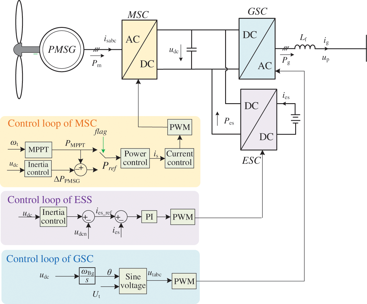
Figure 1: Control structure of the PMSG embed with ESS
where
where
and
In Eq. (1),
where
The machine-side converter of the PMSG employed the vector control according to the flux linkage orientation. The MPTO was achieved based on the outer-power-control and inner-current-control loops (Fig. 1). The input of the MPTO was the rotor speed of the wind turbine. In addition, similar to the conventional PLL-based PMSG, the inertia control loop and/or other control strategies could be added to the MPTO control loops.
To achieve autonomous grid-synchronizing inertia support strategy for the PMSG, the identical relationship between the angular speed ωs of the voltage of GSC and the DC-link voltage (
The energy storage system converter can provide frequency regulation function by absorbing or releasing energy from or to the grid. In Fig. 1, a bidirectional Buck/Boost converter is used to represent the energy storage system converter. As in the control loop, the droop control, which corresponds to the difference between the rated voltage of DC-link (
3 Motion Features between the Synchronous Generator and Grid-Side-Converter of the PMSG
The swing equation of the synchronous generator can be expressed as [19]
where
where
where
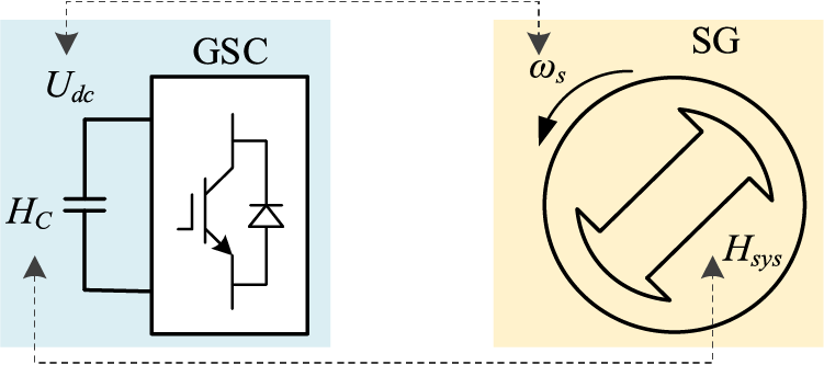
Figure 2: Motion feature similarity between the grid side converter and synchronous generator
4 Short-Term Frequency Regulation Control Strategy for PMSG and ESS
Figs. 3a and 3b display the structures of the PMSG and ESS inertial control strategy, respectively.
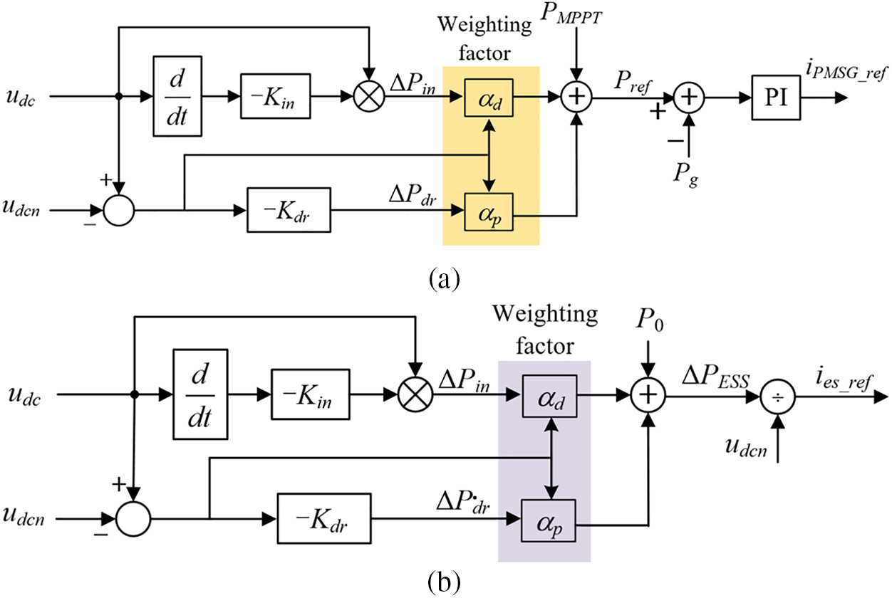
Figure 3: Structure of the inertial control scheme for PMSG and ESS. (a) Structure of the inertial control scheme for PMSG; (b) Structure of the inertial control scheme for ESS
The additional power from the PMSG and ESS can be calculated based on the outputs of the
where
Prior to a frequency disturbance, we have
where P0 is the ESS initial output power. The instantaneous frequency excursion (
where
and
where
where
Similar to reference [15], the system frequency response model performance improved (Fig. 4). The equivalent size of the disturbance (
where
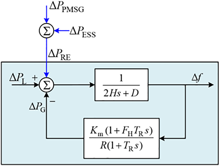
Figure 4: System frequency response considering frequency regulation of PMSG and ESS
The maximum frequency excursion can be derived as [22]
In Eq. (18), the PMSG and ESS could support the system frequency. With the larger
Fig. 5 illustrates the system frequency trajectory after an under-frequency-disturbance. This trajectory can be divided into Zone 1 corresponding to a large
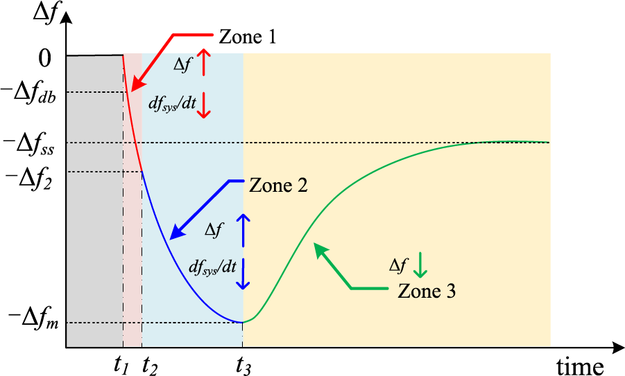
Figure 5: System frequency trajectory following an under-frequency-disturbance
These weights regulate the participation of the
The objective of categorizing the frequency trajectory into the three zones is described as follows:
• Zone 1: To improve
• Zone 2: PMSG and ESS focus on improving the frequency nadir by undervaluing the
• Zone 3: The system frequency rebounds in this region. Here,
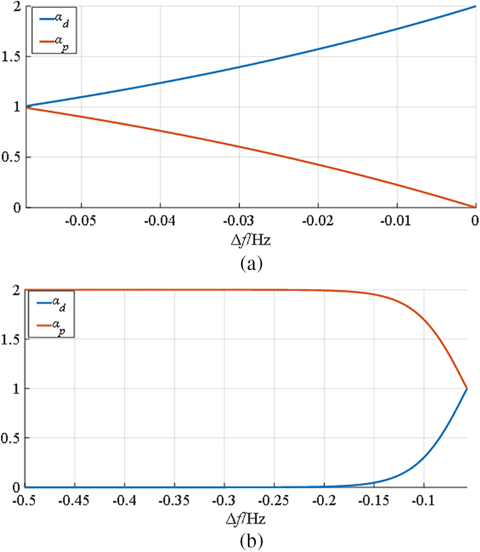
Figure 6: Features of weighting factors: (a) Weighting factor for Zone 1; (b) Weighting factor for Zone 2
To verify the effectiveness of the suggested frequency support strategy, a simulation model system consisting of the PMSG embedded with ESS, one synchronous generator, and two local loads (
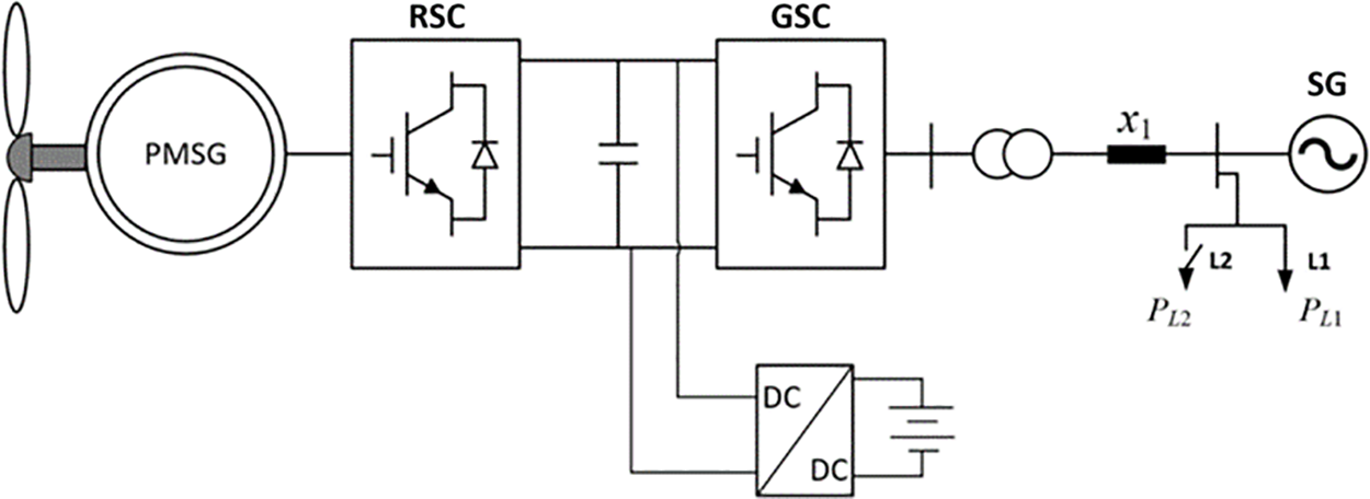
Figure 7: Outline of the test system
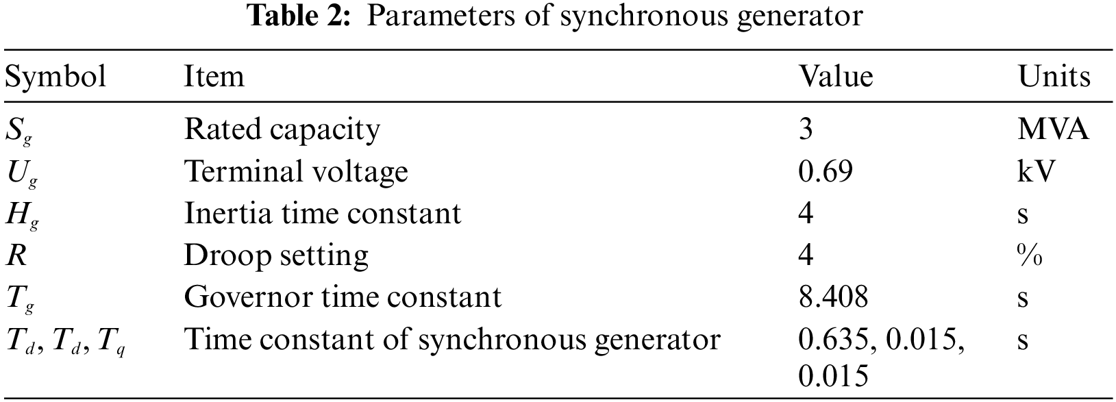
In the simulation results, “MPPT” means no frequency regulation action from the PMSG and ESS. “VIC” means that the PMSG and ESS could provide conventional virtual inertial control strategy with the control coefficient of 10 and 20 for
5.1 Case 1: Scenario of Load Sudden Connection
Fig. 8 illustrates the simulation results of the various strategies for decreasing grid frequency. When no frequency regulation scheme (MPPT) was applied for the PMSG and ESS, the frequency nadir was 49.6 Hz (0.992 p.u.). The voltage of the DC-link decreased to udc = 0.992 p.u. with the same frequency trajectory, as the system frequency is coupled with the DC-link voltage. When the traditional short-term frequency regulation (VIC) with a fixed control coefficient was implemented in the PMSG and ESS, the grid frequency decreased to 49.7 Hz (0.994 p.u.). The DC-link voltage decreased to udc = 0.994 p.u., after the system frequency was increased slightly above that of “MPPT” (Figs. 8a and 8c).
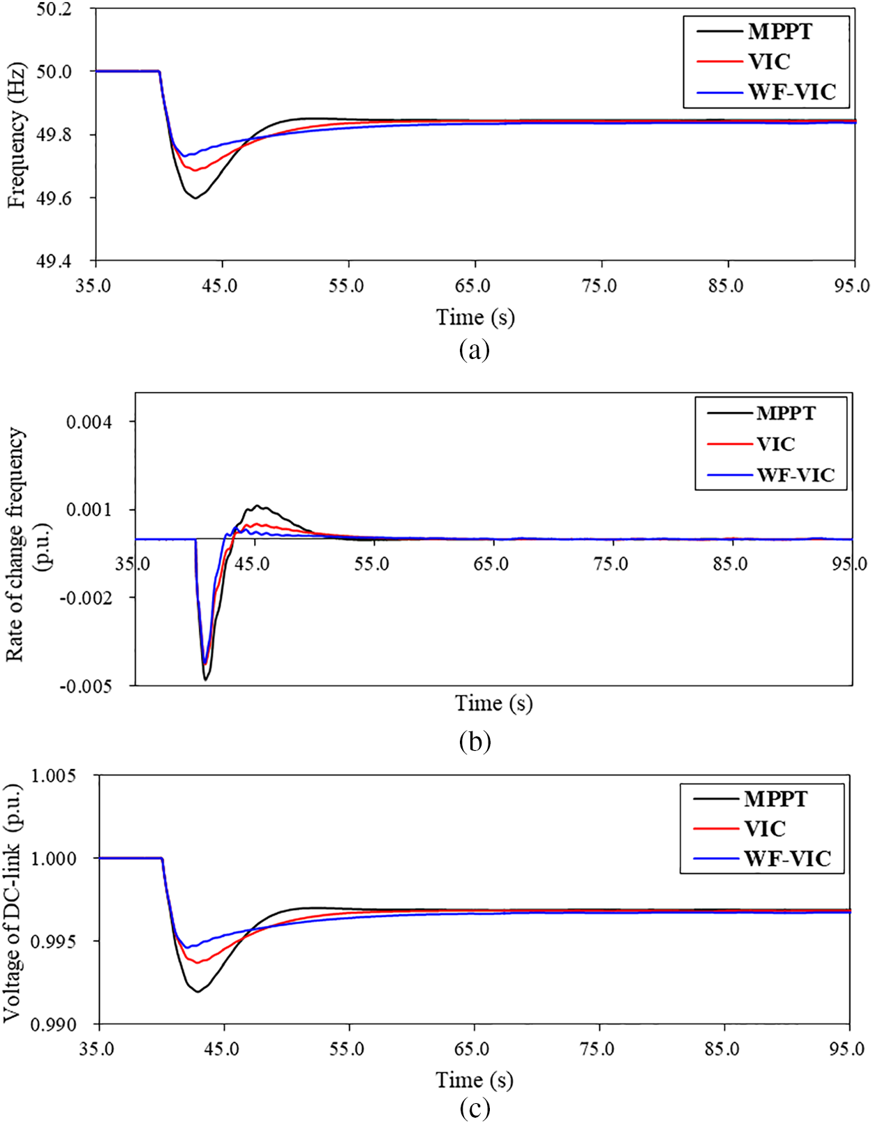

Figure 8: Simulation results: (a) System frequency; (b) Rate of change of frequency; (c) Voltage of DC-link; (d) Output of PMSG; (e) Output of ESS; (f) Rotor speed; (g) Weighting factor
The frequency nadir of the suggested frequency regulation strategy is improved to 0.995 p.u. (49.731 Hz) as well as the voltage of DC-link. In addition, the maximum frequency rate of change (
The maximum power injection of the PMSG for the suggested frequency regulation is 0.214 p.u. which is more than that of the conventional scheme by 0.084 p.u., as shown in Fig. 8d. In addition, the same amount of power is injected from the ESS in p.u. due to the same input and control coefficient. This is the reason why the suggested frequency regulation strategy could improve the maximum deviation of the system frequency and voltage of the DC-link (see Fig. 8e).
The rotor speed nadir of the suggested frequency regulation strategy is 0.974 p.u., which is more than that of the conventional scheme by 0.054 p.u. As a result, more power is injected to the power grid to support the dynamic system frequency (see in Fig. 8f), the same performance would be observed in the state of change of ESS.
As shown in Fig. 8g, at the initial stage of disturbance, ad decreases from two to zero to improve the maximum
5.2 Case 2: Scenario of Load Disconnection
Fig. 9 illustrates the simulation results when the grid frequency increases. For the case of “MPPT”, the frequency nadir is 50.408 Hz (1.008 p.u.), and the voltage of DC-link increases to 1.008 p.u. with the same locus of the system frequency. If the traditional short-term frequency regulation with fixed control coefficient implements in the PMSG and ESS, the grid frequency increases to 50.322 Hz (1.006 p.u.), and the DC-link voltage


Figure 9: Simulation results: (a) System frequency; (b) Rate of change of frequency; (c) Voltage of DC-link; (d) Weighting factor
As in Case 1, ad decreases from two to zero to improve the maximum
High wind power penetration power system would face the problem of system frequency stability due to the power electronics interfaced PMSG. PMSG and ESS could participate in frequency regulation by adding the differential control loop and proportional control loop. Constrained by constant gain, the frequency support capability is restricted. Meanwhile, the available kinetic energy of the PMSG and charging/discharging capacity are restricted. To address the reduced frequency support capability while effectively utilizing the frequency regulation resources, the short-term frequency support of PMSG and ESS is suggested. To this end, firstly, the system frequency response model is addressed, considering the frequency regulation of the PMSG and ESS. The mechanism of the frequency regulation for the PMSG and ESS is analyzed, then the weighting factors are embedded in the control loops to adjust the participation of the differential control and proportional control based on the trajectory of system frequency excursion in the machine side converter. In grid side converter, the voltage of DC-link capacitor would automatically respond to the dynamic system frequency without employing PLL. In addition, the additional ESS with combined inertial control loops is embedded on the DC side of the PMSG to improve the frequency regulation capability further.
Simulation studies clearly verified that the suggested short-term frequency regulation of the voltage source control based on PMSG and ESS can improve the frequency nadir under various system frequency disturbances.
In future, the coordinated control between the PMSG and ESS would be designed considering the available kinetic energy of the PMSG and charging/discharging capacity. In addition, the realistic wind speed conditions would be considered to investigate the effectiveness of the proposed strategy.
Acknowledgement: None.
Funding Statement: This work was financially supported by Open Fund of National Engineering Research Center for Offshore Wind Power “Stabilization Mechanism and Control Technology of the Intelligent Wind-Storage Integration System Based on Voltage-Source and Self-Synchronizing Control (HSFD22007)”.
Author Contributions: All authors contributed to the review & editing of this paper. In addition, Baogang Chen and Fenglin Miao contributed to the methodology, software, analysis.
Availability of Data and Materials: Data would be available after request.
Conflicts of Interest: The authors declare that they have no conflicts of interest to report regarding the present study.
References
1. Hajahmadi, M. A., Gharehpetian, G. B., Firouzi, M., Anvari-Moghaddam, A. (2022). Output power smoothing of wind power plants using unified inter-phase power controller equipped with super-capacitor. Journal of Energy Storage, 54, 105–209. [Google Scholar]
2. Yang, D., Yan, G., Zheng, T., Zhang, X., Hua, L. (2022). Fast frequency response of a DFIG based on variable power point tracking control. IEEE Transactions on Industry Applications, 58(4), 5127–5135. [Google Scholar]
3. Muljadi, E., Gevorgian, V., Singh, M., Santoso, S. (2012). Understanding inertial and frequency response of wind power plants. 2012 IEEE Power Electronics and Machines in Wind Applications, pp. 1–8. IEEE. [Google Scholar]
4. Kabsha, M. M., Rather, Z. H. (2020). A new control scheme for fast frequency support from HVDC connected offshore wind farm in low-inertia system. IEEE Transactions on Sustainable Energy, 11(3), 1829–1837. [Google Scholar]
5. Kim, J., Mujadi, E., Gevorgian, V., Hoke, A. F. (2019). Dynamic capabilities of an energy storage-embedded PMSG system. IEEE Transactions on Industry Applications, 55(4), 4124–4134. [Google Scholar]
6. Eto, J. H. (2010). Use of frequency response metrics to assess the planning and operating requirements for reliable integration of variable renewable generation. USA: Lawrence Berkeley National Laboratory. [Google Scholar]
7. Gevorgian, V., Zhang, Y., Ela, E. (2015). Investigating the impacts of wind generation participation in interconnection frequency response. IEEE Transactions on Sustainable Energy, 6(3), 1004–1012. [Google Scholar]
8. Wang, S., Tomsovic, K. (2019). A novel active power control framework for wind turbine generators to improve frequency response. IEEE Transactions Power System, 33(6), 6579–6589. [Google Scholar]
9. Rocabert, J., Luna, A., Blaabjerg, F. (2012). Control of power converters in AC and DC microgrids. IEEE Transactions on Power Electronics, 27(11), 4734–4749. [Google Scholar]
10. Lorenzo, Z., Andreas, J. R., Janus, M. S., Ioannis, M., Hansen, A. D. (2013). Virtual inertia for variable speed wind turbines. Wind Energy, 16(8), 1225–1239. [Google Scholar]
11. Peng, X., Yao, W., Yan, C., Wen, J., Cheng, S. (2020). Two-stage variable proportion coefficient-based frequency support of grid connected PMSG-WTs. IEEE Transactions Power System, 35(2), 962–974. [Google Scholar]
12. Lee, J., Jang, G., Muljadi, E., Blaabjerg, F., Chen, Z. (2016). Stable short-term frequency support using adaptive gains for a PMSG-based wind power plant. IEEE Transactions on Energy Conversion, 31(3), 1068–1079. [Google Scholar]
13. Yang, D. J., Jin, Z. Y., Zheng, T. Y., Jin, E. S. (2022). An adaptive droop control strategy with smooth rotor speed recovery capability for type III wind turbine generators. International Journal of Electrical Power & Energy Systems, 135, 107532–107542. [Google Scholar]
14. Fu, Y., Wang, Y., Zhang, X. (2017). Integrated wind turbine controller with virtual inertia and primary frequency responses for grid dynamic frequency support. IET Renewable Power Generation, 11(8), 1129–1137. [Google Scholar]
15. Margaris, I. D., Papathanassiou, S. A., Hatziargyriou, N. D., Hansen, A. D., Sorensen, P. (2012). Frequency control in autonomous power systems with high wind power penetration. IEEE Transactions on Sustainable Energy, 3(2), 189–199. [Google Scholar]
16. Ma, Z. H., Li, X. R., Tan, Z. X., Huang, J., He, L. (2019). Integrated control of primary frequency regulation considering dead band of energy storage. Transactions of China Electrotechnical Society, 34(10), 2102–2115. [Google Scholar]
17. Zhang, C., Cai, X., Rygg, A., Molinas, M. (2018). Sequence domain SISO equivalent models of a grid-tied voltage source converter system for small-signal stability analysis. IEEE Transactions on Energy Conversion, 33(2), 741–749. [Google Scholar]
18. Zhu, K., Sun, P., Zhou, L., Du, X., Luo, Q. (2020). Frequency-division virtual impedance shaping control method for grid-connected inverters in a weak and distorted grid. IEEE Transactions on Power Electronics, 35(8), 8116–8129. [Google Scholar]
19. Zhong, Q., Weiss, G. (2011). Synchronverters: Inverters that mimic synchronous generators. IEEE Transactions on Industrial Electronics, 58(4), 1259–1267. [Google Scholar]
20. Zhang, L., Harnefors, L., Nee, H. P. (2010). Power-synchronization control of grid-connected voltage-source converters. IEEE Transactions on Power Systems, 25(2), 809–820. [Google Scholar]
21. Sang, S., Zhang, C., Cai, X., Molinas, M., Zhang, J. et al. (2019). Control of a type-IV wind turbine with the capability of robust grid-synchronization and inertial response for weak grid stable operation. IEEE Access, 7, 58553–58569. [Google Scholar]
22. Shi, Q., Li, F., Cui, H. (2018). Analytical method to aggregate multi-machine SFR model with applications in power system dynamics studies. IEEE Transactions Power System, 33(6), 6355–6367. [Google Scholar]
Cite This Article
 Copyright © 2024 The Author(s). Published by Tech Science Press.
This work is licensed under a Creative Commons Attribution 4.0 International License , which permits unrestricted use, distribution, and reproduction in any medium, provided the original work is properly cited.
 Downloads
 Citation Tools