
 Submit a Paper
 Propose a Special lssue
 Open Access
ARTICLE

Nonlinear Flap-Wise Vibration Characteristics of Wind Turbine Blades Based on Multi-Scale Analysis Method
School of Mechanical and Electrical Engineering, Lanzhou University of Technology, Lanzhou, 730050, China
* Corresponding Author: Yuqiao Zheng. Email:
Energy Engineering 2024, 121(2), 483-498. https://doi.org/10.32604/ee.2023.042437
Received 30 May 2023; Accepted 30 August 2023; Issue published 25 January 2024
 View Full Text
 Download PDF
Abstract
This work presents a novel approach to achieve nonlinear vibration response based on the Hamilton principle. We chose the 5-MW reference wind turbine which was established by the National Renewable Energy Laboratory (NREL), to research the effects of the nonlinear flap-wise vibration characteristics. The turbine wheel is simplified by treating the blade of a wind turbine as an Euler-Bernoulli beam, and the nonlinear flap-wise vibration characteristics of the wind turbine blades are discussed based on the simplification first. Then, the blade’s large-deflection flap-wise vibration governing equation is established by considering the nonlinear term involving the centrifugal force. Lastly, it is truncated by the Galerkin method and analyzed semi-analytically using the multi-scale analysis method, and numerical simulations are carried out to compare the simulation results of finite elements with the numerical simulation results using Campbell diagram analysis of blade vibration. The results indicated that the rotational speed of the impeller has a significant impact on blade vibration. When the wheel speed of 12.1 rpm and excitation amplitude of 1.23 the maximum displacement amplitude of the blade has increased from 0.72 to 3.16. From the amplitude-frequency curve, it can be seen that the multi-peak characteristic of blade amplitude frequency is under centrifugal nonlinearity. Closed phase trajectories in blade nonlinear vibration, exhibiting periodic motion characteristics, are found through phase diagrams and Poincare section diagrams.Keywords
Nomenclature
| Density (kg/m3) | |
| Hub radius | |
| Blade moment of inertia (m4) | |
| Bending stiffness | |
| Axial force | |
| Micro-deformation | |
| Shear angle | |
| Section rotation angle caused by bending moment | |
| Viscosity coefficient | |
| Time scale coefficient | |
| Module of elasticity (N/m2) | |
| Hub rotational speed |
The blade plays a critical role in the operation of wind energy conversion by wind turbines, and its vibration is of great concern to the related researchers. It is a typical thin-walled composite beam structure, and the low-order vibration modes are mainly characterized by flapping and oscillation during its operation. The energy-rich region of the blade during vibration is mainly concentrated in the first and second orders due to the low rotational speed. Previous research has primarily focused on the impact of different parameters on the vibration characteristics. Some scholars simplify the blade as a rotating rigid body molding blade modal analysis to study the impact of different hub speeds on its vibration characteristics [1]. CFD method to study the vibration performance of the blade at different wind speeds, the centrifugal force produces a nonlinear effect that increases the intrinsic frequency and changes the period and amplitude [2,3]. The blade is simplified as an Euler beam model, which can be solved by using the finite element method, the vibration pattern superposition method, and the direct integration method, but the vibration pattern superposition method for modal analysis of the kinetic equations is only applicable to linear calculations [4]. Hamilton’s principle is used to represent the nonlinear kinematics of the blade; under the internal resonance condition, the equations may be analytically solved by the multiscale technique, and the accuracy of the perturbation method and the numerical solution can be compared [5–7].
A nonlinear Reduced-Order Model (ROM) based on large deformation theory and the Galerkin method is proposed for the vibration characteristics of horizontal axis wind turbine blades considering the coupling of waving and pendulum vibration as well as blade rotational rigid body motion [8]. The Euler-Lagrange control equations for dynamic systems are derived based on Hamilton's principle, and the vibration control equations are solved using the Extended Galerkin Method (EGM) by separating the structural variables in space and time and defining the assumed mode shapes to satisfy the basic boundary conditions [9,10]. The fluid-solid interaction effects are used to linearize the simulation of homogeneous blade in-plane vibrations. Van der Pol oscillators are used to characterize the time-varying characteristics of blade vortices and can be used to simulate fluid-solid coupling processes through their interaction with the blade equations of motion [11–15]. Moreover, transition sets made up of bifurcation and hysteresis sets may be built to examine the nonlinear vibration of the blade by including system factors such as singularity theory and van der Pol damping.
Multiple Scale Analysis (MSM) refers to the decomposition of the motion of a system into ingredients on different time scales, thus revealing the dynamics of the system [16]. Through multi-scale analysis, various dynamic characteristics at different time and spatial scales can be discovered in a two-dimensional nonlinear vibration system, such as periodic vibration, chaotic vibration, and twin phenomena. These characteristics not only help us understand the motion law of the system but also provide important references for the control and optimization of the system [17–19]. When studying the stability of the steady-state solution of blade vibration in 1:1 internal resonance using the multi-scale method, the Routh-Hurwitz criterion can be used [20].
The analysis shown above demonstrates that classical finite element methods are typically used in the study of blade flap-wise direction vibration, whereas analytical and semi-analytical approximation approaches are still seldom used [21,22]. The nonlinear characteristics of the centrifugal force and the nonlinear vibration characteristics caused by excitation and hub speed are therefore investigated by varying the excitation amplitude and frequency based on the periodic characteristics of wind-induced blade action [23]. In this work, the modal function and Galerkin method are used to truncate the blade flap-wise vibration control equation, and the vibration response is solved using multi-scale method analysis and Runge-Kutta to investigate the flap-wise vibration displacement at different hub speeds, excitation amplitude, and excitation frequency fluctuation blade vibration characteristics, revealing the influence of parameters such as hub speed on the blade flap-wise vibration.
2 Structural Equations of Motions
2.1 Derivation of the Vibration Governing Equation
The blade’s characteristic of short chord length and long span-wise length is simplified as being rotated around a hub with a radius of
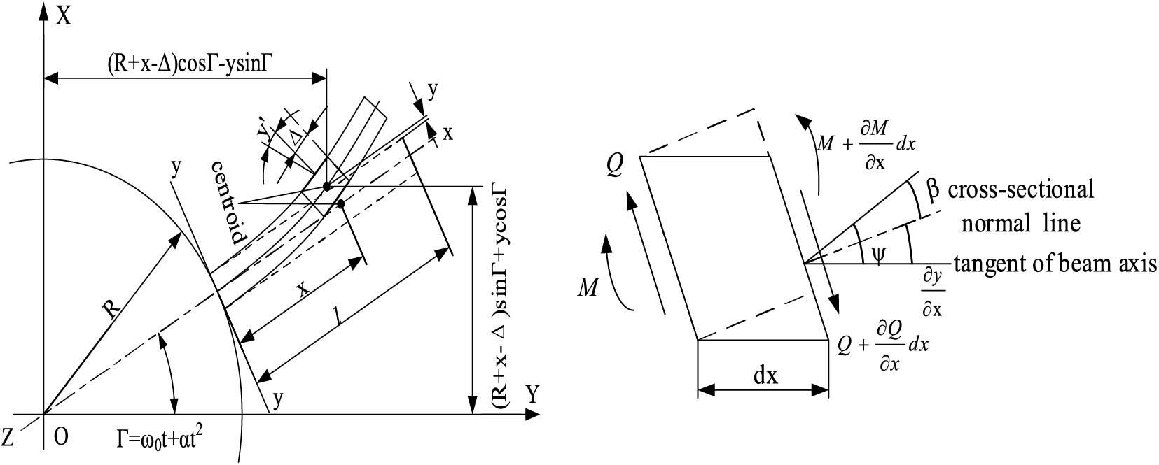
Figure 1: Blade rotating beam model (left) and blade Micro-segment deformation (right)
Drawing upon the geometric theory of large deformations and the beam model theory of blade segments, and limiting our considerations solely to flap-wise vibration, we can derive the differential equation governing blade vibration. This equation can be expressed as follows:
In Eq. (1),
The geometric nonlinear relationship is:
The centrifugal force in the section
According to the assumption of the Kelvin-Voigt blade constitutive relationship, the axial force
By the substitution of Eq. (5) into Eq. (1), the nonlinear differential equation for blade vibration can be obtained. The formula is as follows:
In Eq. (6),
Assuming the blade cantilever beam model, for a homogeneous equal-section blade free vibration,
By introducing the dimensionless variable
2.2 Discretizing Equations Using the Galerkin Method
In engineering practice, the nonlinear factors have less influence on the vibration mode shapes, but more influence on the amplitude and frequency. The original vibration differential equation of the blade is coordinate transformed, and the blade vibration differential equation is transformed into a modal equation expression. With the coordinate transformation, the expression is:
In Eq. (10),
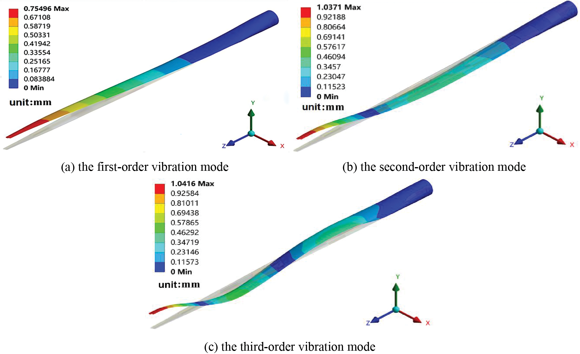
Figure 2: The previous three vibration modes of the blade
Following the assumption of the rotating cantilever beam model of the blade beam the vibration mode function can be selected as [18]:
In Eq. (11),
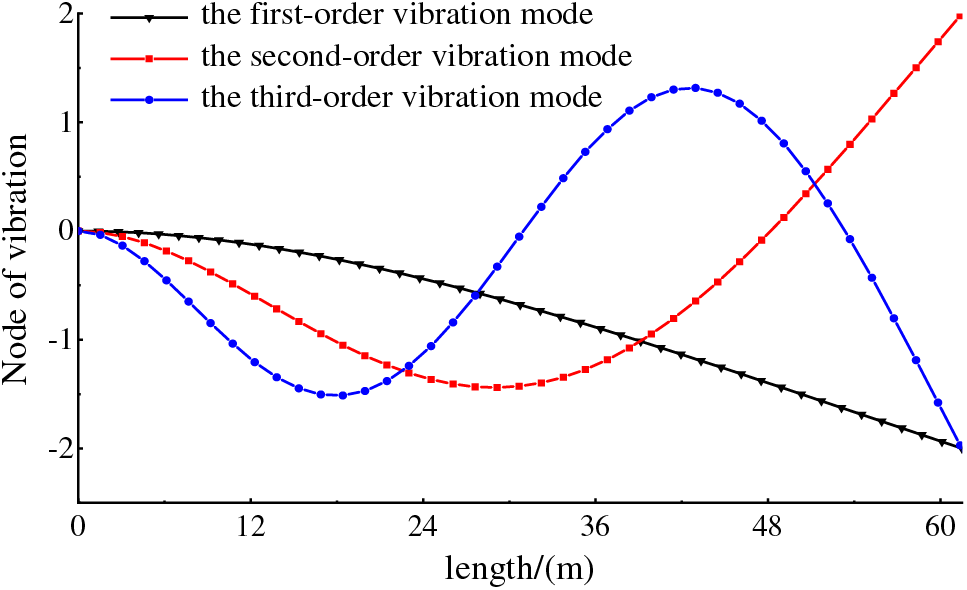
Figure 3: The previous three vibration modes of the blade
Vibrating system in which the first several modes prevail, the first-order truncation of the blade flapping vibration differential equation is executed utilizing the Galerkin method following the vibration displacement modal hypothesis. Taking selected modal functional and coordinates transformation into the vibration differential equation (Eq. (8)) obtained:
In Eq. (12), the coefficients were truncated using the Galerkin method and integrated over the entire length of the blade, resulting in the equation being expressed as:
3 Equations and Mathematical Expressions
Multi-scale method analysis conceives representation response features to be expanded as several time scale functions. Setting the results of the differential equations of blade vibration as a measure of multiple independent variables,
In Eq. (15),
Based on perturbation, the vibration of the blade is studied, and it is noted that
By solving Eq. (16) can be obtained:
By substituting Eq. (18) into Eq. (16) and eliminating the long-term term, can be obtained:
Substituting Eqs. (17) and (18) into Eq. (16), the expression is obtained:
In Eq. (19), cc is the long-term term, eliminating the long-term term can be obtained:
To solve for Z, let its complex form be expressed as:
Eq. (21) involves functions
Substitute Eq. (22) into Eqs. (21) and (23) for comparison, separate the real part and imaginary part, the blade nonlinear vibration characteristics for stable solutions, then there is
Nonlinear terms in the vibration control equations consist of multiple modal time-domain functions, and the coefficients are integrals containing multiple modal forms, which require more complicated calculations. The main resonance response bifurcation response equations of the blade nonlinear vibration system are solved with numerical methods, by giving a value that both
In Eq. (24), the amplitude is denoted by
4 Simulation Results and Discussion
The blade vibration equation is solved by the numerical method of Runge-Kutta to study the nonlinear flap-wise vibration characteristics of the NREL 5 MW wind turbine blade. Where the wind turbine hub radius
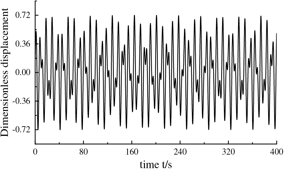
Figure 4: The vibration displacement response curve of the unexcited hub at a speed of 12.1 rpm
In Fig. 4, the blade vibration displacement response curve is shown at a hub speed of 12.1 rpm, and the absolute value of the dimensionless displacement amplitude varies in the range of 0.127–0.72, with a minimum amplitude of 0.127. The overall vibration dimensionless displacement response exhibits periodic changes, and the nonlinear influence leads to a local small-scale response fluctuation in the response curve. Phase diagrams showing the evolution trajectory of different states over the vibration system of the blade are shown in Fig. 5.
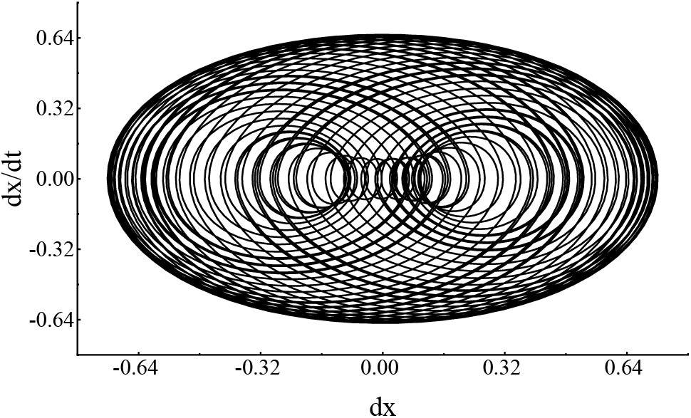
Figure 5: The phase diagram when the unexcited hub speed is 12.1 rpm
In Fig. 5, the motion state is a closed trajectory, indicating that the blade vibration is a stable motion. The two ends of the dx axis are consistent with the vibration displacement response value at the hub speed of 12.1 rpm, the leftmost is −0.72, the rightmost is 0.72, and the middle change value is the displacement response change value change area is −0.72–0.72. dx/dt changes response range is −0.65–0.65, and the points in the phase diagram are the regular points. The existence of nonlinear terms will make the relationship curve between amplitude and frequency show special patterns such as multi-peaks and distortions, and the relationship between amplitude and frequency of different wheel speeds is shown in Fig. 6.
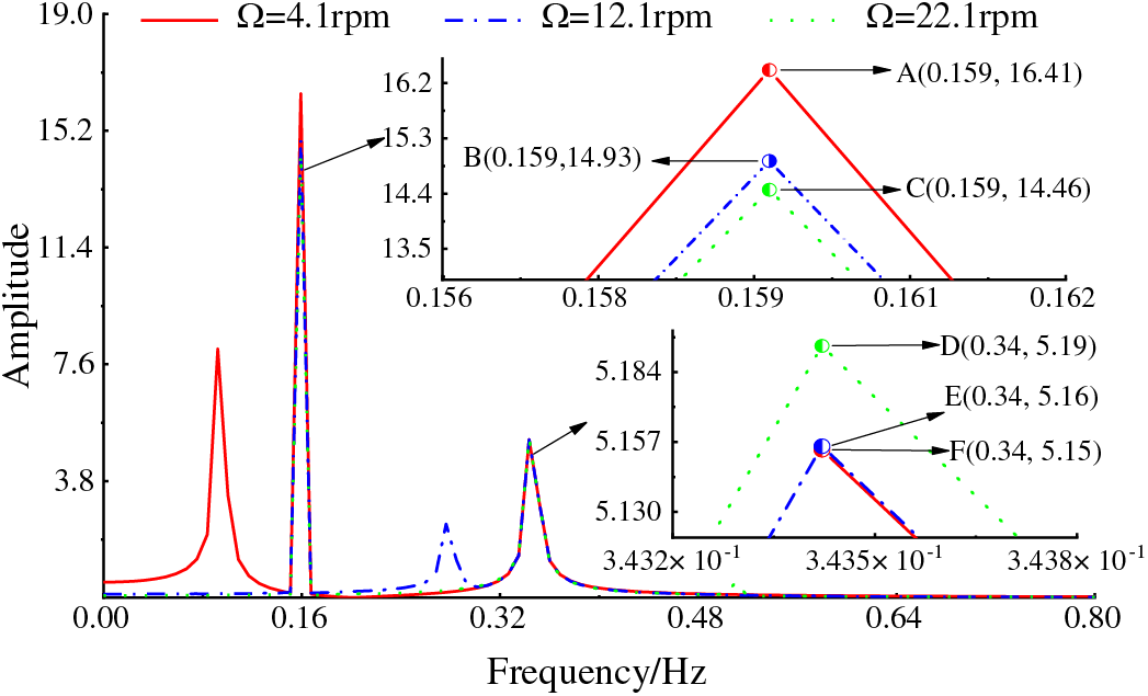
Figure 6: Relationship between blade vibration amplitude and frequency response under different wheel speeds
The amplitude-frequency response curves of blade-free vibration under different wheel speeds are shown in Fig. 6. The multi-peak phenomenon varies with different speeds, and peaks occur simultaneously at frequencies of 0.159 and 0.34 for all speeds. When the frequency is 0.159, the maximum amplitude of the low speed is 16.41, followed by the rated speed with an amplitude of 14.93, and the minimum amplitude is at the high speed, which is 14.46. Points D, E, and F have peaks at a frequency of 0.34, with the first peak at 5.19 for the high speed, the second at 5.16, and point F is the peak for the low-speed amplitude.
FEM simulation software is used to solve the Campbell diagram analysis of blade vibration. The constraint conditions and loads are set to be exactly the same as the numerical simulation, and the finite element simulation results are compared with the numerical settlement results. The Campbell diagram of blade vibration is drawn as shown in Fig. 7.
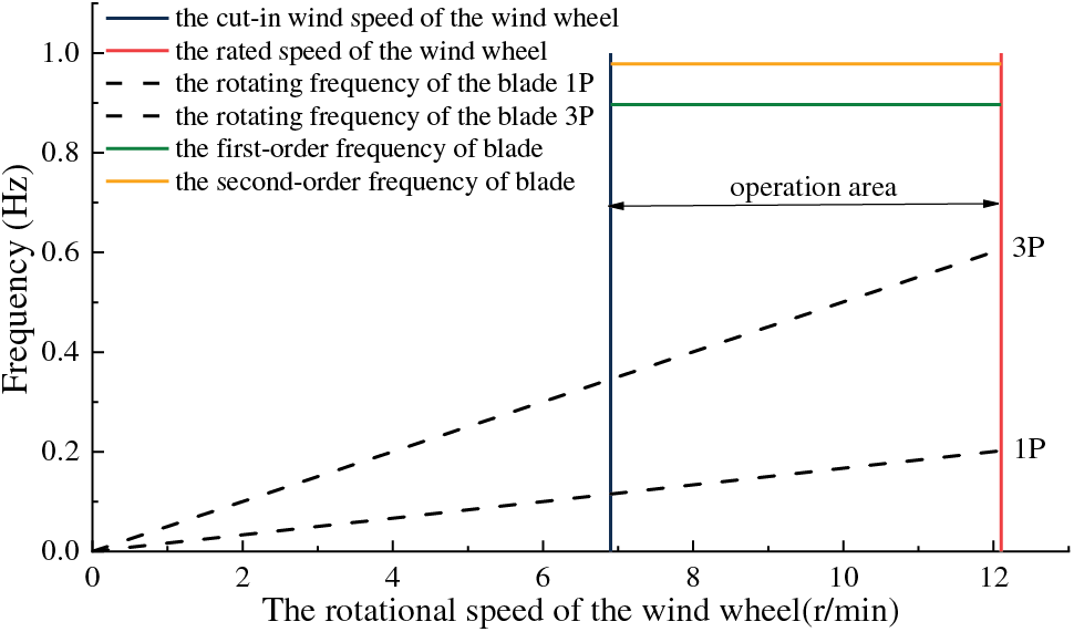
Figure 7: Campbell diagram of blade vibration
It can be seen in Fig. 7 that the two vertical lines are the cut-in speed and the rated speed of the wind wheel, respectively. The ray starting from the origin represents the rotation frequency of the blade, and the two horizontal lines are the first and second-order frequencies of the blade vibration. The rated speed of the wind wheel is 12.1 rpm, and the blade rotation frequency 1P is 0.202 Hz and 3P is 0.606 Hz. The first-order natural frequency of the blade is 0.887 Hz, which is 77.5% and 32.5% different from the rotation frequency 1P and the rotation frequency 3P of the blade. The first-order and second-order natural frequencies of the blade do not intersect with the blade rotation frequency in the wind wheel cut-in speed and rated speed range, that is, the blade does not resonate in the actual working process. That the curve direction and trend are in general agreement with the numerical results, of the same magnitude, indicates that the results are credible.
When the blades are rotated with the rotor hub, the effect of wind on the blades is shown as periodic changes, which can be simplified as periodic load
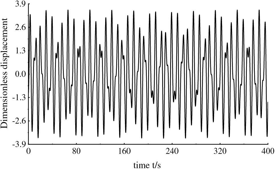
Figure 8: The vibration displacement response curve when the excitation amplitude F = 1.23 and the hub speed is 12.1 rpm
In Fig. 8, with the blade loaded periodic load and hub speed of 12.1 rpm, the maximum magnitude of the dimensionless displacement of flapping vibration is 3.16, with an increased magnitude of 2.44 compared to that without considering wind load, which is a 71% increase. It is hard to visualize the movement space evolution trajectory from the vibration displacement response curve, and the phase trajectory after the introduction of wind load was visualized for the system movement space evolution as shown in Fig. 9.
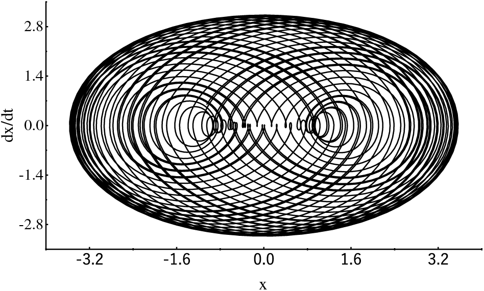
Figure 9: The phase diagram when the excitation amplitude F = 1.23 and the wheel speed is 12.1 rpm
In Fig. 9, the equilibrium position and amplitude nonlinear calculation results are larger than the results when wind load is not considered. dx axis values at both ends increase from −0.72 to −3.53, the maximum value changes from 0.72 to 3.53, and the middle change value is the displacement response change value. dx/dt changes response range, −3.16 to 3.16. With the rated rotational speed of the hub of 12.1 rpm, the effect of different excitation amplitudes on the nonlinear vibration of the blade is investigated, and the relationship between the amplitude of the frequency of the period is shown in Fig. 10.
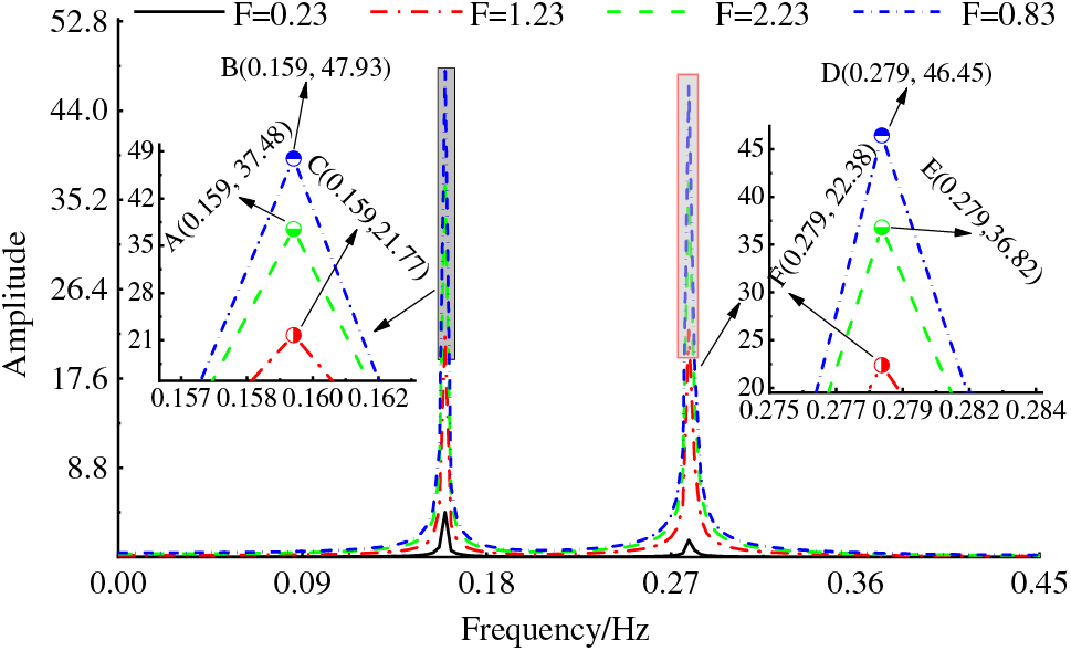
Figure 10: The amplitude-frequency response relationship of different F values when the wheel speed is 12.1 rpm
In Fig. 10, as the hub is at rated speed, the amplitude-frequency response is bimodal, and the excitation amplitude has a remarkable influence on amplitude so that when the excitation amplitude increased with 1, the corresponding vibration amplitude response increased 10 times. The excitation amplitude has little effect on the frequency. The first peak frequency in the rated speed in Fig. 9 is consistent with that without external excitation in Fig. 6, which is 0.159 Hz. The second peak has a slight change, which is 0.34 without excitation. The frequency is reduced to 0.279 under external load excitation.
When the external excitation load frequency fluctuated minutely, both the frequency and amplitude for the nonlinear vibration dimensionless displacement response varied. Adopt excitation loads fundamental frequency and hub-rated speed consistent at 12.1 rpm,
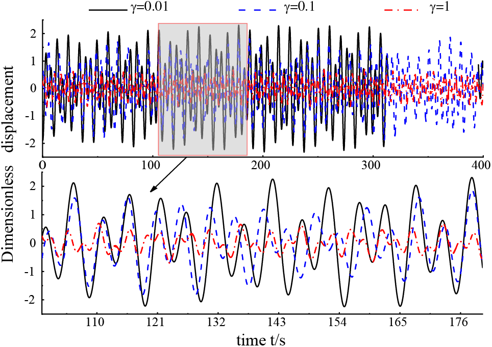
Figure 11: Displacement response curves with different values of
In Fig. 11, the vibration displacement response of the blade changes obviously with the increase of
To visually observe the spatial state of blade vibration motion changing with the fluctuation of external excitation frequency, the spatial phase diagram at
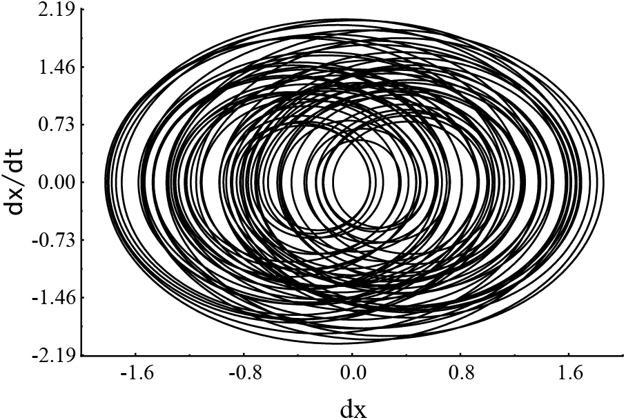
Figure 12: Wheel speed of 12.1 rpm and phase diagram at
In Fig. 12, it can be observed by comparing Figs. 7 and 11 that when there is a fluctuation in the excitation frequency, there is a significant change in the spatial evolution trajectory of blade vibration, and the maximum response amplitude decreases from 3.53 to 2.27, which is reduced by 36%. The maximum value of dx/dt also decreases from 3.16 to 2.04, which is a reduction of 35.4% compared to when there is no fluctuation. Furthermore, significant changes in the evolutionary trajectories of many movements can be observed in the intermediate region of the phase diagram, as shown in Figs. 9 and 10.
In the phase space, the displacement dy and the velocity dy/dt are regarded as the conjugate variables to calculate the local maximum of the steady state process. The characteristics and variations of the system motion are presented by intercepting the Poincare cross-section to explore the trajectory of the evolution of the blade vibratory motion. The Poincare section is visualized by taking the rated speed of 12.1 rpm and no external load excitation, the external excitation amplitude of F = 10.12 but no fluctuation of the external excitation frequency, the external excitation amplitude of F = 10.12 and the external excitation frequency fluctuation of a = 0.1, as shown in Fig. 13.
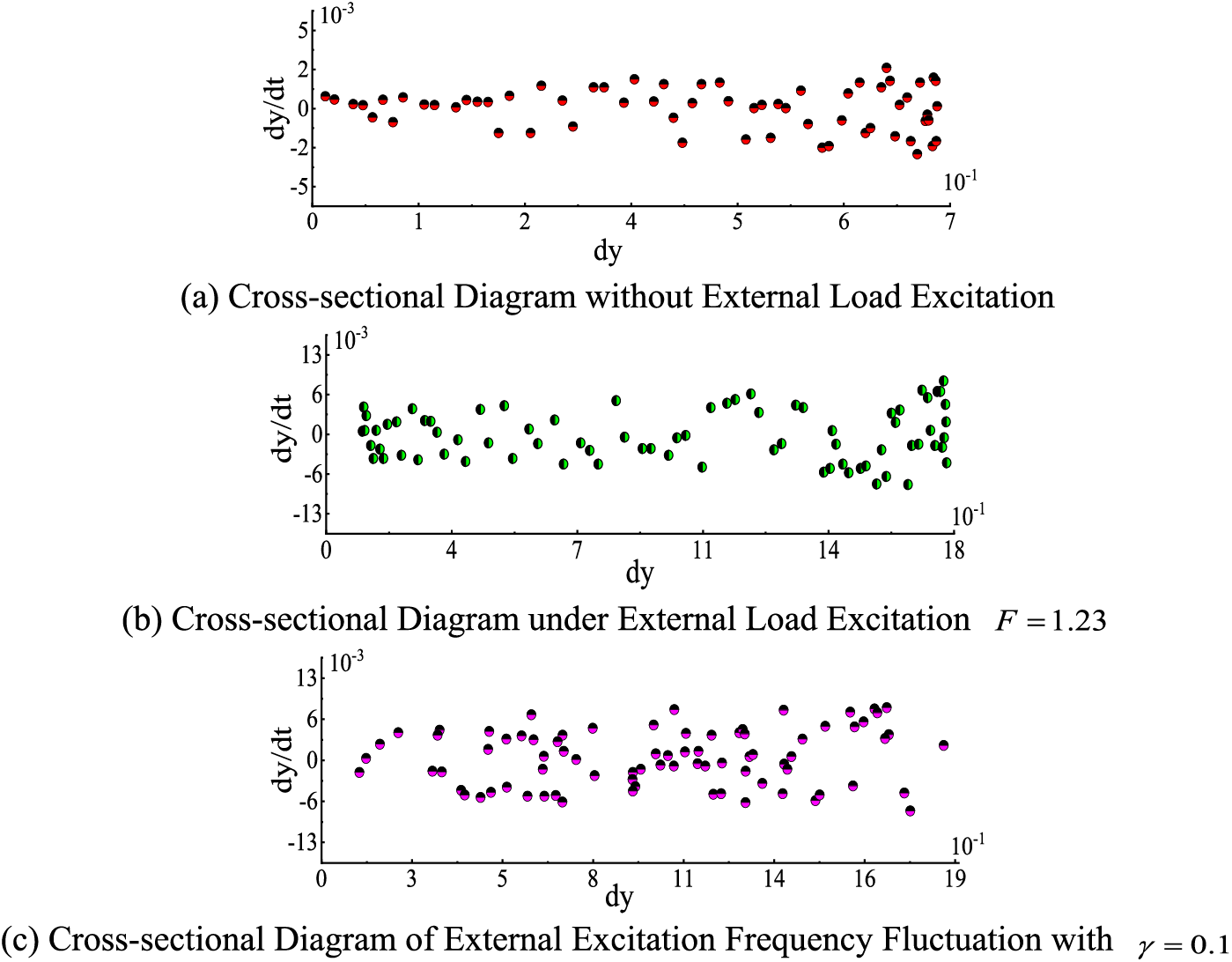
Figure 13: Poincare section plot
In Fig. 13, it can be determined whether the vibration is chaotic. It can be seen from Fig. 11 that when there is no external excitation on the blade, the maximum value of dy is 0.753 and the maximum value of dy/dt is 2.5 × 10⁻³. As external load excitation is introduced, there is a 57.67% increase in the maximum value in dy, which is 1.779, and the maximum value of dy/dt is increased to 8.6 × 10⁻³, with an increased ratio of 70.93%; the frequency fluctuation a = 0.1 of the external load excitation increases the dy/dt value by 0.077 and decreases the dy/dt value by 0.410−3 compared to no frequency fluctuation. All of the discrete points on the cross-section are minority, without obvious fractal structure, and the blade vibration is periodical movement.
In this work, the wind turbine blade is simplified as a cantilever beam spinning around the hub. Following the finite element simulation analysis, the suitable vibration mode function is chosen, shortened using the Galerkin method, solved using the Runge-Kutta numerical method, and compared to the finite element simulation findings. The study’s findings indicate that:
(1) There is a significant variable effect of hub speed change in the blade vibration amplitude with time. Various periphery speed blade free vibration amplitude frequency response is separate, although, at the frequency of 0.159 and 0.34, each speed appears at the simultaneous peak; frequency is 0.159, minor speed amplitude is the maximum, then the rated speed amplitude, magnitude at high speed is minimum, respectively, 16.41, 14.93, 14.46.
(2) At rated speed, when harmonic external excitation is introduced, the maximum amplitude value becomes 3.16, with an amplification ratio of 71%. Amplitude frequency response is bimodal, and the excitation amplitude influence on that amplitude is notable, when the excitation amplitude increased by 1, the corresponding vibration amplitude response increased 10 times. The frequency of the first peak is consistent with that without external excitation, which is 0.159 Hz, and the second peak has a slight change, decreasing from 0.34 without excitation to 0.279 with a reduced rate of 18%.
(3) As the external excitation frequency of the load fluctuates, the blade vibration spatial evolution trajectory alters, and the maximum value of the response decreases from 3.53 to 2.27, which is reduced at a ratio is 36%. The change in the motion evolution trajectory can be easily seen from the middle area of the phase diagram.
Acknowledgement: The authors would like to acknowledge the generous help from the School of Mechanical and Electronic Engineering and the College of Automation.
Funding Statement: This work was supported by the National Natural Science Foundation of China (No. 51965034).
Author Contributions: The authors confirm their contribution to the paper as follows: study conception and design: Yuqiao Zheng, Qifa Lang; data collection: Qifa Lang; analysis and interpretation of results: Qifa Lang, Chenglong Shi; draft manuscript preparation: Tiancai Cui, Heyu Zhang. All authors reviewed the results and approved the final version of the manuscript.
Availability of Data and Materials: All data generated or analyzed during this study is included in this published article.
Conflicts of Interest: The authors declare that they have no conflicts of interest to report regarding the present study.
References
1. Sun, R., Li, C., Ding, Q., Chen, W. P. (2018). Modal and vibration analysis for the large wind turbine blade. Journal of Engineering for Thermal Energy and Power, 33(10), 400–407. [Google Scholar]
2. Algolfat, A., Wang, W. Z., Albarbar, A. (2022). Comparison of beam theories for characterisation of a NREL wind turbine blade flap-wise vibration. Proceedings of the Institution of Mechanical Engineers Part A: Journal of Power and Energy, 236(7), 1350–1369. [Google Scholar]
3. Karimi, B., Hamed, M. (2018). Nonlinear kinematics analysis and internal resonance of wind turbine blade with coupled flap-wise and edgewise vibration modes. Journal of Sound and Vibration, 116, 390–408. [Google Scholar]
4. Ju, D. Y., Sun, Q. (2017). Modeling of a wind turbine rotor blade system. Journal of Vibration and Acoustics, 139(5), 1–15. [Google Scholar]
5. Evgueni, S., Sudhanva, K. C. (2019). Determination of natural frequencies and mode shapes of a wind turbine rotor blade using Timoshenko beam elements. Wind Energy Science, 4(1), 57–69. [Google Scholar]
6. Behnam, K., Hamed, M. (2018). Nonlinear kinematics analysis and internal resonance of wind turbine blade with coupled flap-wise and edgewise vibration modes. Journal of Sound and Vibration, 435, 390–408. [Google Scholar]
7. Jokar, H., Mahzoon, M., Vatankhah, R. (2020). Dynamic modeling and free vibration analysis of horizontal axis wind turbine blades in the flap-wise direction. Renewable Energy, 146, 1818–1832. [Google Scholar]
8. Jokar, H., Vatankhah, R., Mahzoon, M. (2021). Nonlinear vibration analysis of horizontal axis wind turbine blades using a modified pseudo arc-length continuation method. Engineering Structures, 247, 1103–1131. [Google Scholar]
9. Farsadi, T. (2022). Variable thickness thin-walled rotating blades made of functionally graded porous materials. Proceedings of the Institution of Mechanical Engineers, Part C: Journal of Mechanical Engineering Science, 236(14), 7674–7689. [Google Scholar]
10. Farsadi, T. (2021). Enhancement of static and dynamic performance of composite tapered pretwisted rotating blade with variable stiffness. Journal of Vibration and Acoustics, 143(2), 021009. [Google Scholar]
11. Wang, D., Hao, Z. F., Chen, Y. S., Zhang, Y. X. (2018). Dynamic and resonance response analysis for a turbine blade with varying rotating speed. Journal of Theoretical and Applied Mechanics, 56(1), 31–42. [Google Scholar]
12. Navadeh, N., Goroshko, I., Zhuk, Y., Etminan, M. F., Soleiman, F. A. (2021). Finite element analysis of wind turbine blade vibrations. Vibration, 4(2), 310–322. [Google Scholar]
13. Huang, J. D., Xia, H. J., Li, D. Y., Guo, K. X. (2020). Nonlinear aeroelastic modal analysis of large wind turbine flexible blades. Journal of Mechanical Engineering, 56(14), 174–182. [Google Scholar]
14. Li, Z. G., Song, C. Y., Gao, Z. Y., Zhang, L. R., Wang, J. W. (2017). Development of aeroelastic coupling numerical model for large-scale megawatt wind turbine and its application. Proceedings of the CSEE, 1–13 (In Chinese). [Google Scholar]
15. Yin, Y. J., Liao, M. F., Lv, P. (2017). Analysis of transient respnse of wind turbine blade based timsheko beam. Taiyangneng Xuebao/Acta Energiae Solaris Sinica, 38(9), 2552–2558 (In Chinese). [Google Scholar]
16. Rabiee, F. H., Jafari, A. A. (2022). Nonlinear forced vibration of rectangular plates by modified multiple scale method. Proceedings of the Institution of Mechanical Engineers, Part C: Journal of Mechanical Engineering Science, 236(9), 4621–4630. [Google Scholar]
17. Li, Z. G., Cheng, Y. Y., Gao, Z. Y., Zhang, L. R., Wang, J. W. (2022). Numerical model of structural dynamic response for wind turbine flexible blad. Journal of Engineering Thermophysics, 43(9), 2374–2381. [Google Scholar]
18. Luo, R. (2021). Generalized formulation for free vibration of elastic solids with static loads and application to rotating tapered cantilever beam vibration. Journal of Vibration Testing and System Dynamic, 5(2), 149–168. [Google Scholar]
19. Farzaneh, R., Asghar, A. J. (2022). Nonlinear forced vibration of rectangular plates by modified multiple scale method. Proceedings of the Institution of Mechanical Engineers, Part C: Journal of Mechanical Engineering Science, 236(9), 4621–4630. [Google Scholar]
20. Malte, R., Ould, M. E. (2020). A numerical method to compute global resonant vibrations of ships at forward speed in oblique waves. Applied Ocean, 14(1), 95–166. [Google Scholar]
21. Waseem, M., Ajmal, M., Kim, T. W. (2015). Development of a new composite drought index for multivariate drought assessment. Journal of Hydrology, 527, 30–37. [Google Scholar]
22. Mohanraj, M., Pandiyarajan, R., Jayakumar, K. S., Antony, P. D., Sabarish, S. et al. (2022). Determination of vibration analysis in single and double cracked cantilever numerical beam. Materials Today: Proceedings, 52, 462–466. [Google Scholar]
23. Liang, B., Zhang, T. T. (2018). Numerical optimization and cyber-physical- social computing for vibrations of the elliptical treadmill based on GSO-BPNN model. IEEE Access, 6, 10886–10895. [Google Scholar]
Cite This Article
 Copyright © 2024 The Author(s). Published by Tech Science Press.
This work is licensed under a Creative Commons Attribution 4.0 International License , which permits unrestricted use, distribution, and reproduction in any medium, provided the original work is properly cited.
 Downloads
 Citation Tools