
 Submit a Paper
 Propose a Special lssue
 Open Access
ARTICLE

A Compact UHF Antenna Based on Hilbert Fractal Elements and a Serpentine Arrangement for Detecting Partial Discharge
1 Guangzhou Power Supply Bureau of Guangdong Power Grid Co., Ltd., China Southern Power Grid, Guangzhou, 510620, China
2 State Key Laboratory of Power Transmission Equipment Technology, School of Electrical Engineering, Chongqing University, Chongqing, 400044, China
* Corresponding Author: Xiang Lin. Email:
Energy Engineering 2024, 121(5), 1127-1141. https://doi.org/10.32604/ee.2024.046861
Received 17 September 2023; Accepted 11 December 2023; Issue published 30 April 2024
 View Full Text
 Download PDF
Abstract
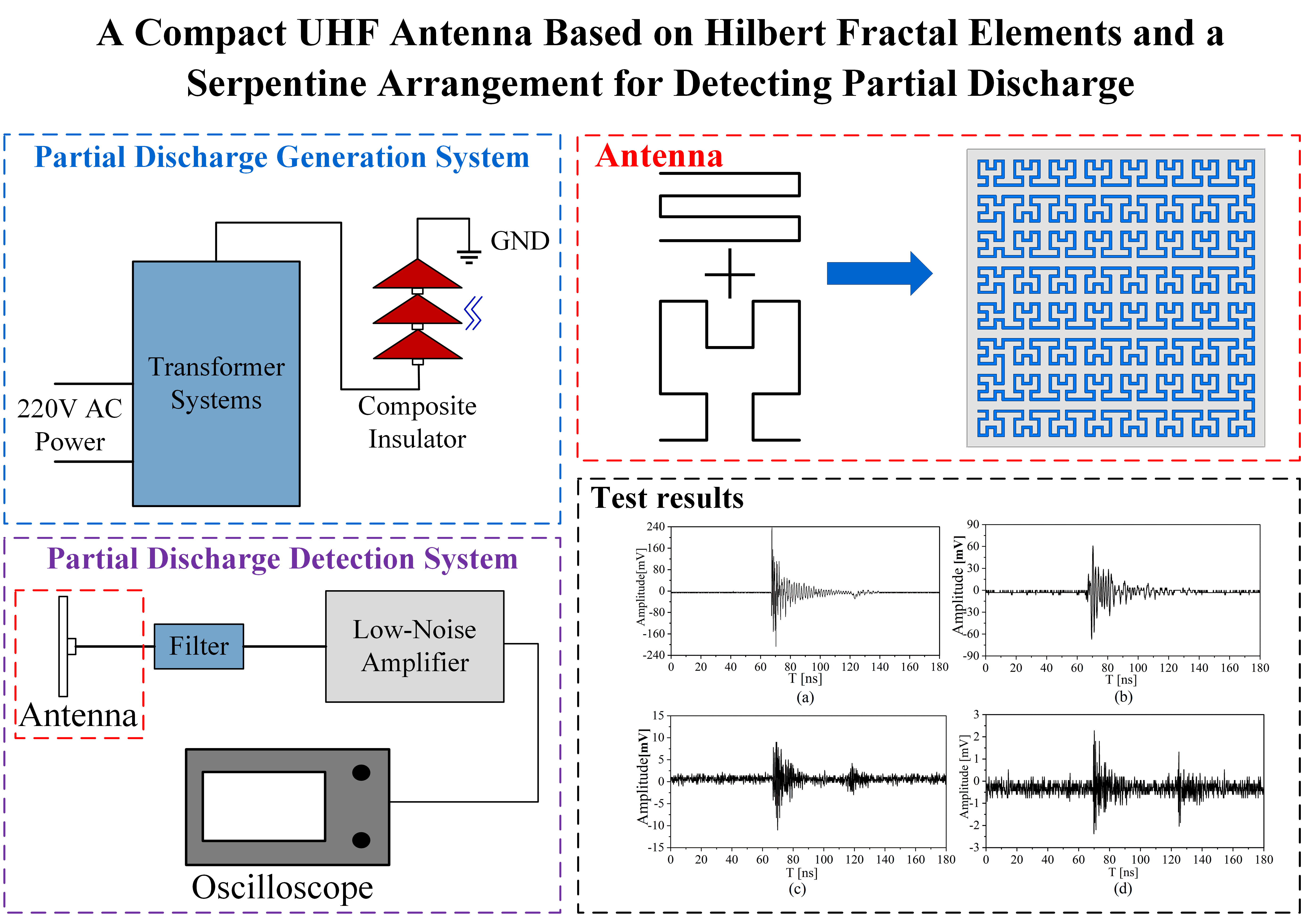
Efforts to protect electric power systems from faults have commonly relied on the use of ultra-high frequency (UHF) antennas for detecting partial discharge (PD) as a common precursor to faults. However, the effectiveness of existing UHF antennas suffers from a number of challenges such as limited bandwidth, relatively large physical size, and low detection sensitivity. The present study addresses these issues by proposing a compact microstrip patch antenna with fixed dimensions of 100 mm × 100 mm × 1.6 mm. The results of computations yield an optimized antenna design consisting of 2nd-order Hilbert fractal units positioned within a four-layer serpentine arrangement with a fractal unit connection distance of 3.0 mm. Specifically, the optimized antenna design achieves a detection bandwidth for which the voltage standing wave ratio is less than 2 that is approximately 97.3% of the UHF frequency range (0.3–3 GHz). Finally, a prototype antenna is fabricated using standard printed circuit board technology, and the results of experiments demonstrate that the proposed antenna is capable of detecting PD signals at a distance of 8 m from the discharge source.Graphic Abstract
Keywords
Nomenclature
| UHF | Ultra-high frequency |
| PD | Partial discharge |
| VSWR | The voltage standing wave ratio |
| PCB | Printed circuit board |
| SHU | Serpentine-Hilbert unit |
| s | Spacing |
The partial discharge (PD) of conductors at high voltage through degraded insulation materials is recognized as a major contributor to faults in electric power systems [1–3]. Moreover, accidents involving high voltage power equipment are closely associated with the degradation of insulation materials. Therefore, efforts to ensure the performance and safety of power systems increasingly depend on the real-time detection of PD in high voltage power equipment [4]. Four predominant methodologies have been employed for detecting PD, including (1) the measurement of pulsed currents, (2) the detection of ultrasonic signals, (3) chemical analysis of the gas employed in gas-insulated power equipment, and (4) applying ultra-high frequency (UHF) antennas. Each of these have unique advantages and disadvantages.
For the first method, electric power systems are subject to pulsed currents under PD, and the magnitude of this unusually high current can be applied to determine the magnitude and location of the PD. The disadvantages of this method are that the measurement frequency band is mainly distributed in the low frequency band of 10–400 kHz, which is not suitable for on-line monitoring and has weak anti-interference ability [5]. In the second method, the acoustical disturbances of PD events are detected by ultrasonic sensors fixed on the inner and outer walls of the equipment, and the magnitudes of the signals collected at known sensor locations are employed to determine the magnitude and location of the PD. The disadvantage of this method is its low positioning accuracy owing to inevitable variations in the internal structures of different electrical equipment, which unpredictably affects the speed and attenuation of sound waves [6]. In the third method, PD alters the constituent components and concentrations in the gas employed in gas-insulated power equipment. The disadvantage of this method is the large time delay between the occurrence of the PD and the detection of the characteristic gas [7]. In the fourth method, the occurrence of PD generates high bandwidth electromagnetic signals in the UHF band that radiate outward from the point of origin. This signal can then be captured by appropriately designed UHF antennas, and the point of origin extracted from the signal intensities captured by multiple antennas. As can be seen, the wide bandwidth signal provides a wealth of information in real time and is not strongly sensitive to the internal structures of electrical equipment. Moreover, the UHF detection method provides high sensitivity and good immunity to noise, and has therefore been widely used in electric power systems [8,9].
Current research has focused on designing UHF antennas with ultra-wideband signal capability over frequencies ranging from 0.3 to 3 GHz. However, the UHF signals arising from PD events are subject to some loss when propagating through an inhomogeneous medium because electromagnetic waves are subject to reflection at the interfaces of different media, resulting in what is denoted as standing wave losses. These losses are commonly quantified based on the voltage standing wave ratio (VSWR), where the sensitivity and noise immunity of an antenna increase as the VSWR approaches 1. Antennas utilized for PD detection in power equipment must have VSWR values less than 2 within their operating frequency band [10,11]. In this paper, we denote the frequency band with VSWR < 2 as the detection frequency band of PD. Moreover, size is an important parameter in antenna design because small size facilitates installation in a wide variety of power equipment. For example, Qi et al. [12] combined a coplanar waveguide antenna and multilayer substrates to obtain a broad bandwidth antenna with dimensions of up to 282 mm × 242 mm × 8.75 mm. Similarly, Wang et al. [13] designed an Archimedean spiral antenna with a diameter exceeding 200 mm. Although both antennas exhibited excellent performance in the UHF band, their large size hindered their practical installation in power equipment, which has been demonstrated to be limited effectively to area dimensions of the order of 100 mm × 100 mm [14].
In recent years, microstrip patch antennas relying on the plane filling functionality of Hilbert fractal structures have been increasingly employed as UHF antennas due to their many advantages, such as small size, lightweight, ease of mounting, and low cost [15–17]. However, standard Hilbert fractal antennas have a relatively narrow detection frequency band for which the VSWR < 2. Three different schemes have been employed to address this issue. The first scheme implements a laminated structure, which improves the bandwidth and gain performances of the antenna by introducing a superimposed coupling structure to stimulate neighboring resonant frequencies [18]. However, this method often leads to a significant increase in antenna size and weight and is generally not preferred. The second scheme relies on increasing the Hilbert fractal order directly, and thereby increases the extent to which the plane is filled [19]. Finally, the third scheme aligns the Hilbert fractal structures with a tertiary structure like a rectangular spiral curve, which increases the fill factor in a more structurally simplistic manner than in the second scheme [20].
The present work addresses the above-discussed issues by proposing a compact microstrip patch antenna the incorporates Hilbert fractal units within a multiple-layer serpentine arrangement. The serpentine-like arrangement is commonly utilized in antenna design due to its advantages such as high fill factor and structural simplicity. This arrangement also enhances electromagnetic wave propagation and increases the effective aperture of the antenna, which improves the sensitivity of the UHF antenna. This paper applies the following design requirements for the antenna: (1) the dimensions of the antenna are set as 100 mm × 100 mm × 1.6 mm, making it easily installable in power equipment; (2) the antenna must have as large a detection bandwidth share for which VSWR < 2 as possible within the frequency range 0.3 to 3 GHz. The detection bandwidth of the proposed serpentine-Hilbert unit (SHU) antenna with the target dimensions is optimized based on the electric field distribution map of the microstrip layer obtained using Ansys HFSS full wave electromagnetic simulation software over a frequency range of 0.3 to 3 GHz. The process yields an optimum SHU structure composed of 2nd-order Hilbert fractal units within a four-layer serpentine arrangement and a fractal unit spacing of 3.0 mm. Specifically, the optimized antenna design achieves a detection bandwidth that is approximately 97.3% of the UHF frequency range based on computations. Finally, a prototype antenna is fabricated using standard printed circuit board (PCB) technology, and the good performance of the proposed antenna design is demonstrated by the results of experiments.
2.1 Microstrip Patch Antenna Structure
As shown in Fig. 1, a microstrip patch antenna structure consists of microstrip layer, a substrate, and a ground layer. The performance of a microstrip patch antenna is heavily influenced by both its size and the structure of its radiating elements in the microstrip layer. However, to achieve miniaturization, the antenna size was limited to dimensions of 100 mm × 100 mm × 1.6 mm, and the focus was applied to optimizing the structure of its Hilbert unit radiating elements with a coaxial feed.
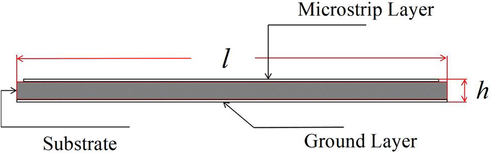
Figure 1: Schematic illustrating the microstrip patch antenna model
2.2 Hilbert Fractal Curve and Serpentine Arrangement
As shown in Fig. 2, a Hilbert fractal curve is a continuous curve without any intersection points, where each higher-order Hilbert fractal curve consists of copies, arrangements, and connections of the curves from the previous order that increasingly fills the space at a higher rate using new curve structures with self-similarity. The entire two-dimensional space is filled as the order of the curve approaches infinity. Fig. 2 represents the Hilbert fractal curves of first to fourth order, respectively.
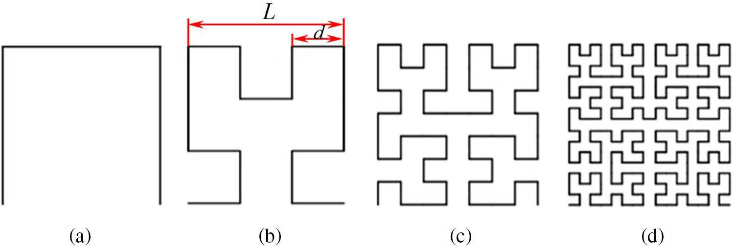
Figure 2: Hilbert fractal curves of different orders: (a) 1st-order curve; (b) 2nd-order curve; (c) 3rd-order curve; (d) 4th-order curve
The relationships between the overall side length L unit side length d, total line length S, and order n of a Hilbert fractal curve can be described by the following equations:
The center frequency of an antenna is positively correlated with S. Therefore, the space-occupying design of Hilbert fractal curves enables the creation of antennas of relatively small sizes. The researchers introduced a serpentine curve combined with Hilbert fractal, and designed a new curve structure. The structure of serpentine curves is shown in Fig. 3. Fig. 3 represents the serpentine curves of one to four-layer, respectively. In addition, the proposed SHU antenna design composed of a 2nd-order Hilbert fractal unit with a 2-layer serpentine curve is depicted in Fig. 4. The 2nd-order Hilbert fractal unit and 2-layer serpentine curve is respectively depicted in Figs. 4a and 4b. Fig. 4c shows the proposed SHU antenna.
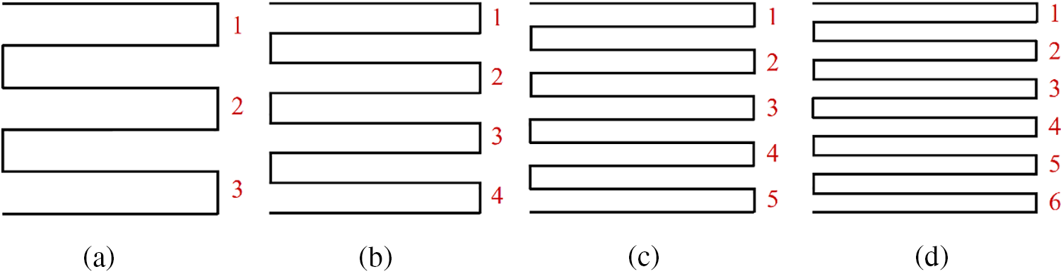
Figure 3: (a) 2-layer serpentine curve; (b) 3-layer serpentine curve; (c) 4-layer serpentine curve; (d) 5-layer serpentine curve
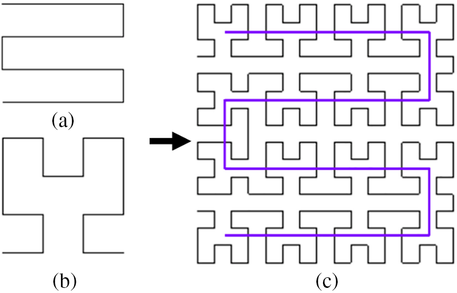
Figure 4: Design process for the proposed serpentine-Hilbert unit (SHU) antenna (a) 2nd-order; (b) 2-layer SHU curve; (c) wire component of length s connecting Hilbert fractal elements
3.1 Design Parameters and Modeling
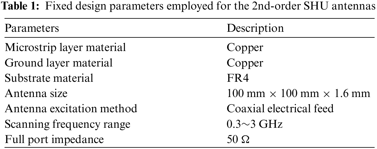
The optimization process applied for designing the SHU antenna considered the 2nd-order Hilbert unit curve applied to serpentine structures composed of 2, 3, 4, and 5 layers as the microstrip layer, and FR-4 glass-reinforced epoxy laminate material as the dielectric substrate. The design parameters are listed in Table 1. In addition, we applied a Hilbert fractal element spacing of s = 1.8 mm (Fig. 4b) for all computations in this subsection.
The designed antennas are illustrated in Fig. 5, where a microstrip layer that maximizes its coverage within a 100 mm × 100 mm area is utilized. Fig. 5 represents the SHU antennas with 2nd-order Hilbert and 2 to 5-layer serpentine arrangements. As can be seen, the coaxial feed is connected at the beginning of the Hilbert fractal curve in the upper left corner of the area.
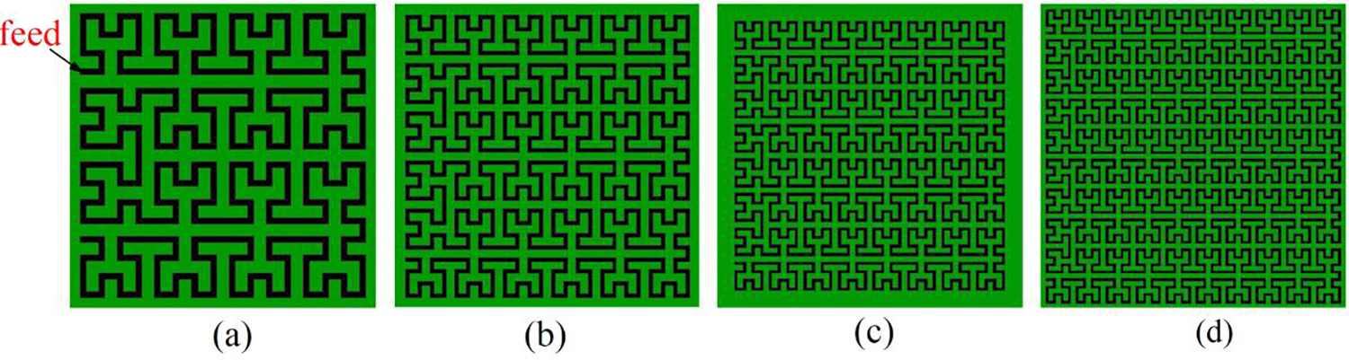
Figure 5: SHU antennas with 2nd-order Hilbert units and multiple-layer serpentine arrangements considered in the optimization process: (a) 2 serpentine layers; (b) 3 serpentine layers; (c) 4 serpentine layers; (d) 5 serpentine layers
3.2 Comparison of Simulation Results
The VSWR values obtained from HFSS simulations for the four SHU antennas composed of 2nd-order Hilbert units with 2–5 serpentine layers over the frequency range of interest are presented in Figs. 6a–6d, respectively. The black dotted lines in the figures represent the condition VSWR = 2. Only the data points below the black dotted lines are included in the PD detection bandwidth of the antennas. The percentage of the UHF band (i.e., 0.3–3 GHz) included within the PD detection bandwidth of each of the antennas is listed in Table 2.
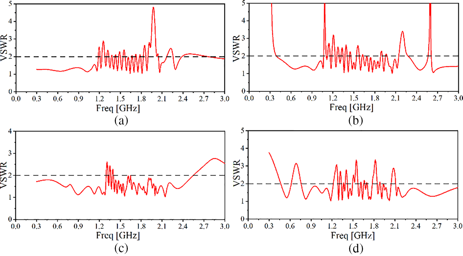
Figure 6: VSWR values of SHU antennas composed of 2nd-order Hilbert units with different numbers of serpentine layers as a function of frequency: (a) 2 serpentine layers; (b) 3 serpentine layers; (c) 4 serpentine layers; (d) 5 serpentine layers
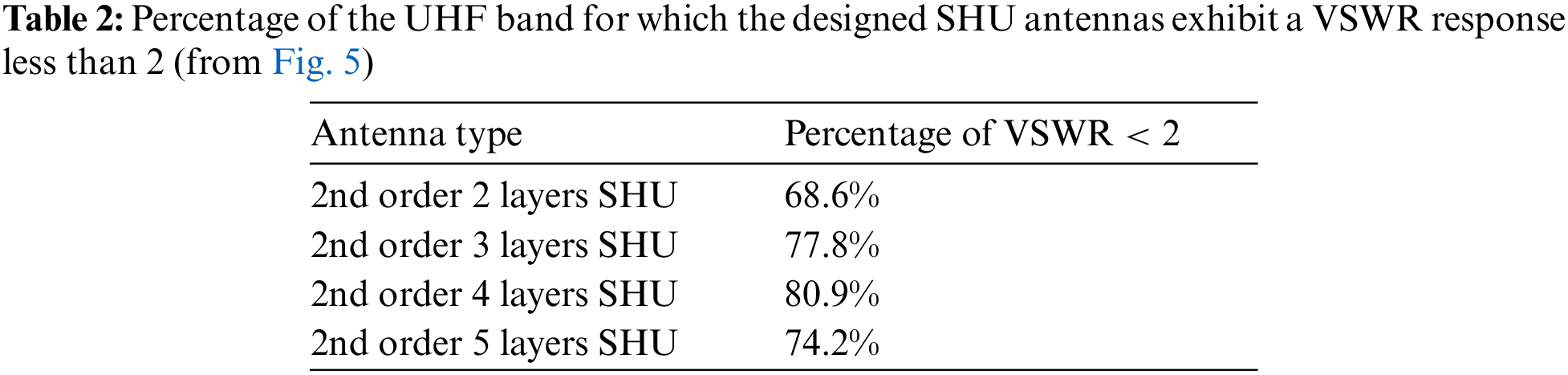
According to Table 2, the percentage of the detection band relative to the entire UHF band gradually increases to a maximum value of 80.9% with an increasing number of serpentine layers from 2 to 4. However, further increase in the number of layers to 5 has a negative impact on the detection bandwidth of the antenna. Therefore, the 2nd-order, 4-layer SHU structure was selected as the optimal microstrip layer for the proposed antenna.
3.3 Optimizing the Spacing of Fractal Elements
The fractal element spacing of a 2nd-order, 4-layer SHU antenna structure was subject to optimization by varying the spacing s of the Hilbert fractal elements based on the previous work of Liu et al. [21]. The importance of s on antenna performance is illustrated by the electric field distribution shown in Figs. 7 and 8, where the electric field intensity is considerably greater in the region connecting the 2nd-order Hilbert fractal elements. Therefore, the present work considered values of s over a limited range of 1.8, 2.1, 2.4, 2.7, 3.0, and 3.3 mm, which ensured that the antenna size did not exceed the target value listed in Table 1.
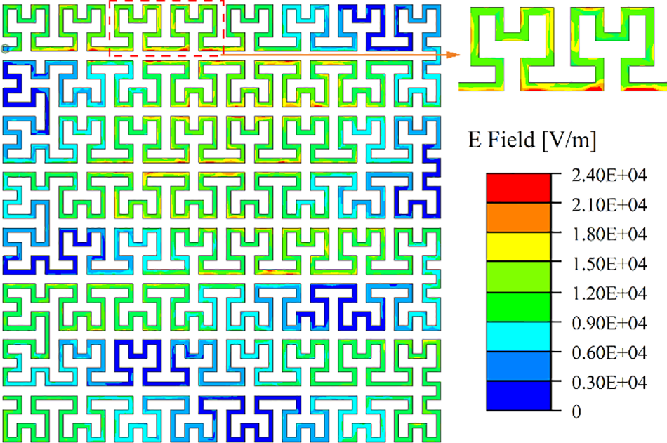
Figure 7: Electric field distribution obtained for a 2nd-order, 4-layer SHU antenna
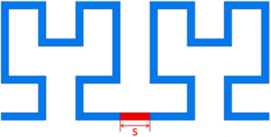
Figure 8: The spacing s of the Hilbert fractal elements
The VSWR values obtained over the frequency range of interest from HFSS simulations for the six SHU antennas composed of 4 serpentine layers and 2nd-order Hilbert units with values of s in the range of 1.8–3.3 mm are presented in Fig. 9, respectively. Again, only the data points below the black dotted lines (VSWR = 2) are included in the PD detection bandwidth of the antennas. The percentage of the UHF band (i.e., 0.3–3 GHz) included within the PD detection bandwidth of each of the antennas is listed in Table 3.
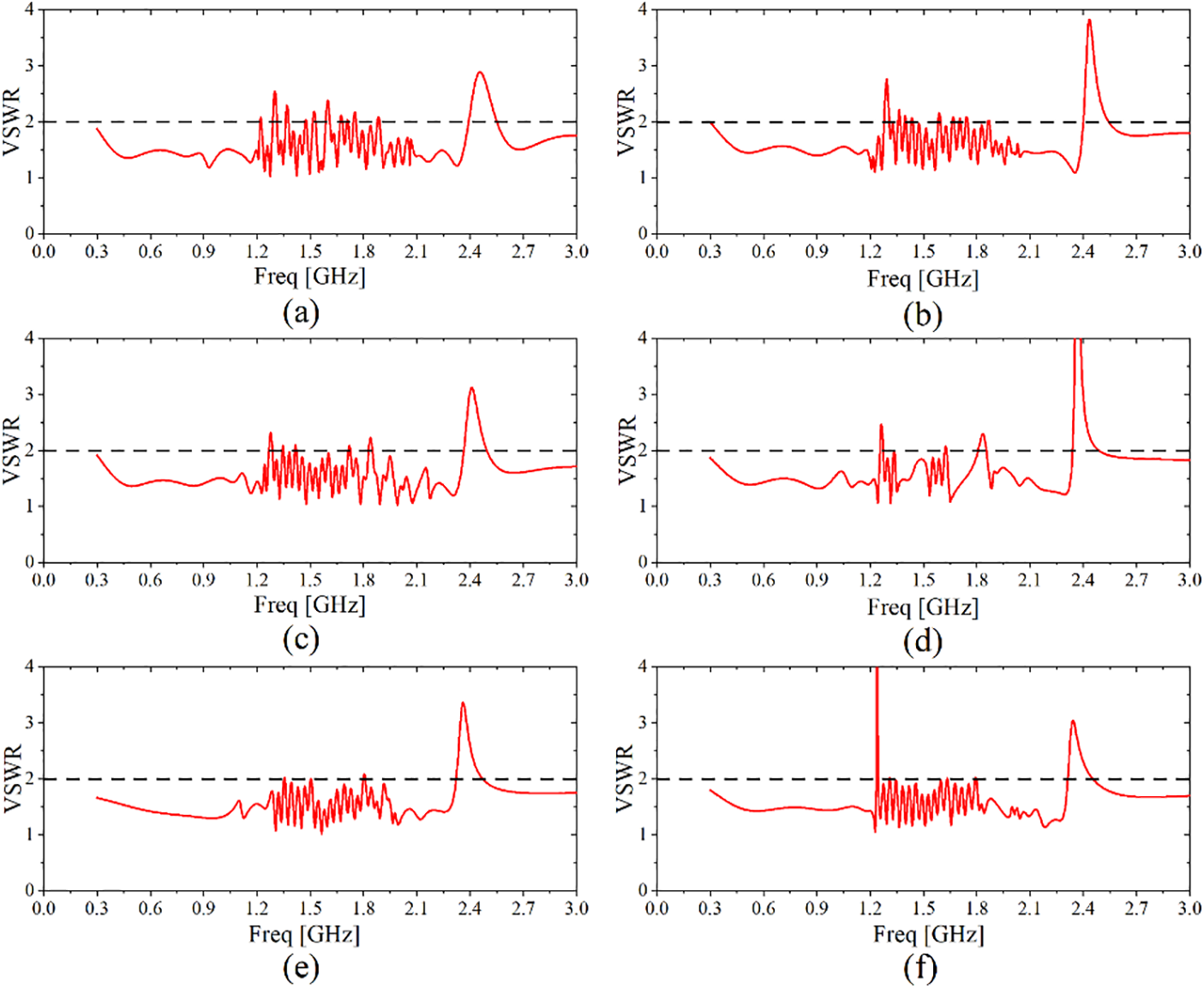
Figure 9: VSWR values of 2nd-order, 4-layer SHU antennas with different spacing values s as a function of frequency: (a) s = 1.8 mm; (b) s = 2.1 mm; (c) s = 2.4 mm; (d) s = 2.7 mm; (e) s = 3.0 mm; (f) s = 3.3 mm
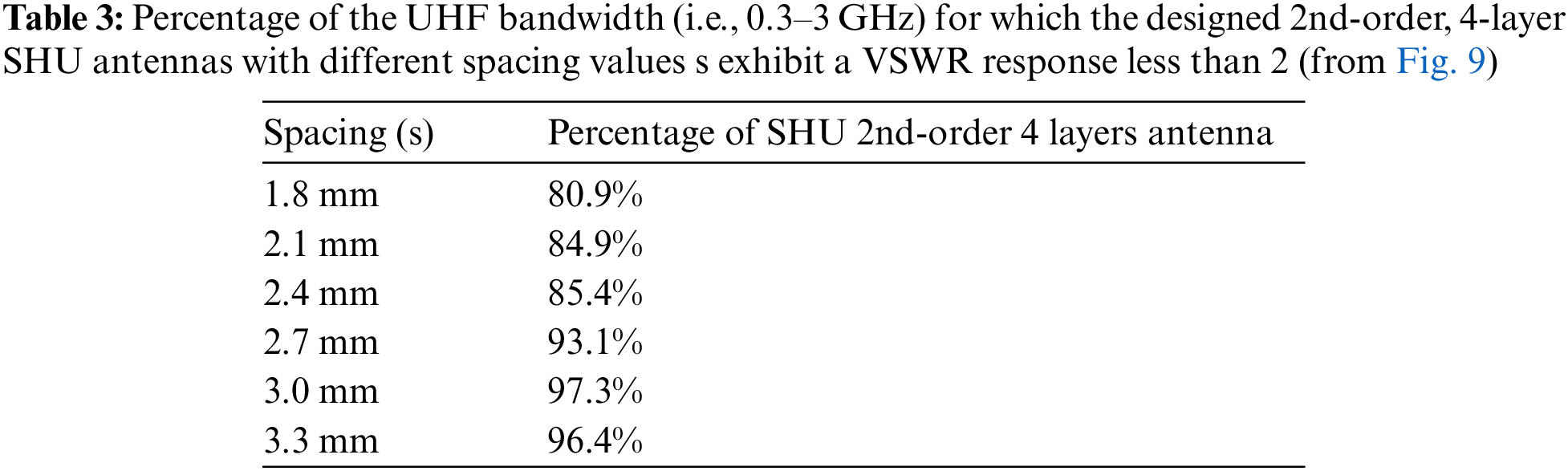
According to Table 3, the percentage of the detection band relative to the entire UHF band gradually increased to a maximum value of 97.3% with increasing s from 1.8 to 3.0 mm. However, further increase in s to 3.3 mm had a negative impact on the detection bandwidth of the antenna. Therefore, the 2nd-order, 4-layer SHU structure with s = 3.0 mm was selected as the optimal microstrip layer for the proposed antenna.
According to the above work, researchers simulated the 2nd-order, 4-layer SHU antenna with s = 3 mm, and obtained its radiation pattern, as shown in Fig. 10.
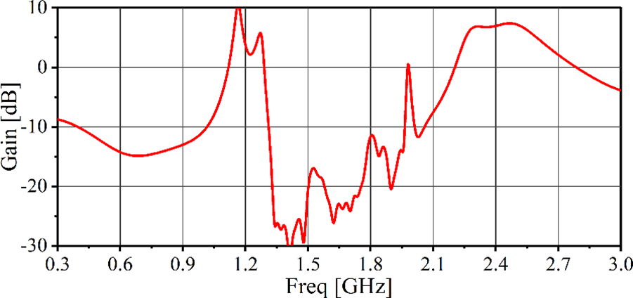
Figure 10: Radiation pattern of 2nd-order, 4-layer SHU antenna
4.1 Physical Modeling and Testing
A prototype 2nd-order, 4-layer SHU antenna with s = 3.0 mm was fabricated according to the specifications listed in Table 1 using standard PCB technology, and images of the antenna are presented in Figs. 11a–11c. As can be seen, the overall dimensions of the antenna were 100 mm × 100 mm × 1.6 mm and weight about 37 g.
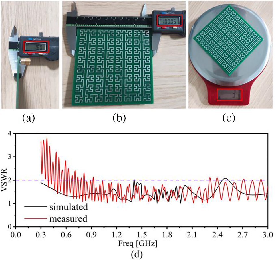
Figure 11: Prototype 2nd-order, 4-layer SHU antenna with s = 3.0 mm fabricated according to the specifications listed in Table 1 using standard PCB technology: (a) side view; (b) front view; (c) weight; (d) VSWR curves obtained from simulation and experimental measurements
The VSWR of the prototype antenna was obtained over a frequency range of 0.3–3 GHz using a RIGOL RSA5608N real-time spectrum analyzer. The experimentally obtained VSWR spectrum is compared in Fig. 11d with the simulated results originally presented in Fig. 9e.
As can be seen, the experimental results deviate to some extent from the computational results, particularly at relatively low frequencies. As a result, the percentage of the UHF band for which the prototype SHU antenna exhibited a VSWR response less than 2 was actually 88%, rather than the 97.3% value obtained from computations. Such differences can be attributed to the testing environment and human factors. For example, the prototype antenna is physically connected to the spectrum analyzer using a coaxial cable, which requires the soldering of an SMA connector onto the antenna. As a result, imperfect soldering joints and the presence of electronic equipment interference at the testing site can be expected to impact the measured VSWR values, whereas no such impact occurs during the computations [20]. Nonetheless, the experimental results demonstrate that the prototype antenna provides a detection bandwidth for PD signals that occupies a significant percentage of the UHF frequency range, enabling the sensitive detection of PD signals.
4.2 Detection of Partial Discharge Signals
The experimental platform employed in the PD detection tests involving the prototype SHU antenna is illustrated schematically in Fig. 12. The primary components of the experimental platform include the following. (1) A YDQB 10 kA/50 kV transformer system (Luzhou Special Transformer Co. Ltd.,) powered by a 220 V AC power supply. (2) Composite insulator with a discharge threshold of 10 kV. The insulator was treated according to the International Electrotechnical Commission (IEC) standard 60507:2013 for artificial pollution testing, where a mixture of sodium chloride and kaolin was prepared in a 1:5 ratio by mass, dissolved in an appropriate amount of deionized water, evenly stirred with a brush, coated on the surface of the insulator, and allowed to dry naturally. (3) The optimized 2nd-order, 4-layer SHU antenna. (4) A high-pass filter with a cutoff frequency of 300 MHz designed using PathWave Advanced Design System (ADS) software (Keysight Technologies) was applied to the antenna output to remove relatively low-frequency signals, the structure and parameters of the filter are shown in Fig. 13. (5) Low-noise amplifier with a gain of 20 dBm and frequency range of 20 MHz to 6 GHz for amplifying the received signals. (6) A RIGOL MSO2202A multi-channel oscilloscope was employed for observing, recording, and analyzing the PD signals captured by the antenna. Images of the experimental platform are presented in Fig. 14.
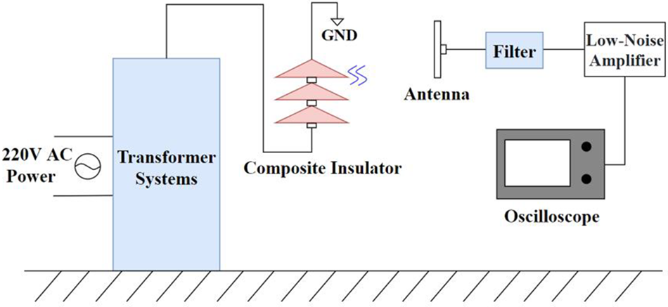
Figure 12: Schematic illustrating the experimental platform employed in the PD detection tests
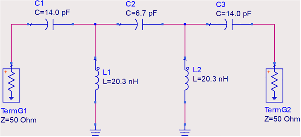
Figure 13: The structure and parameters of high-pass filter
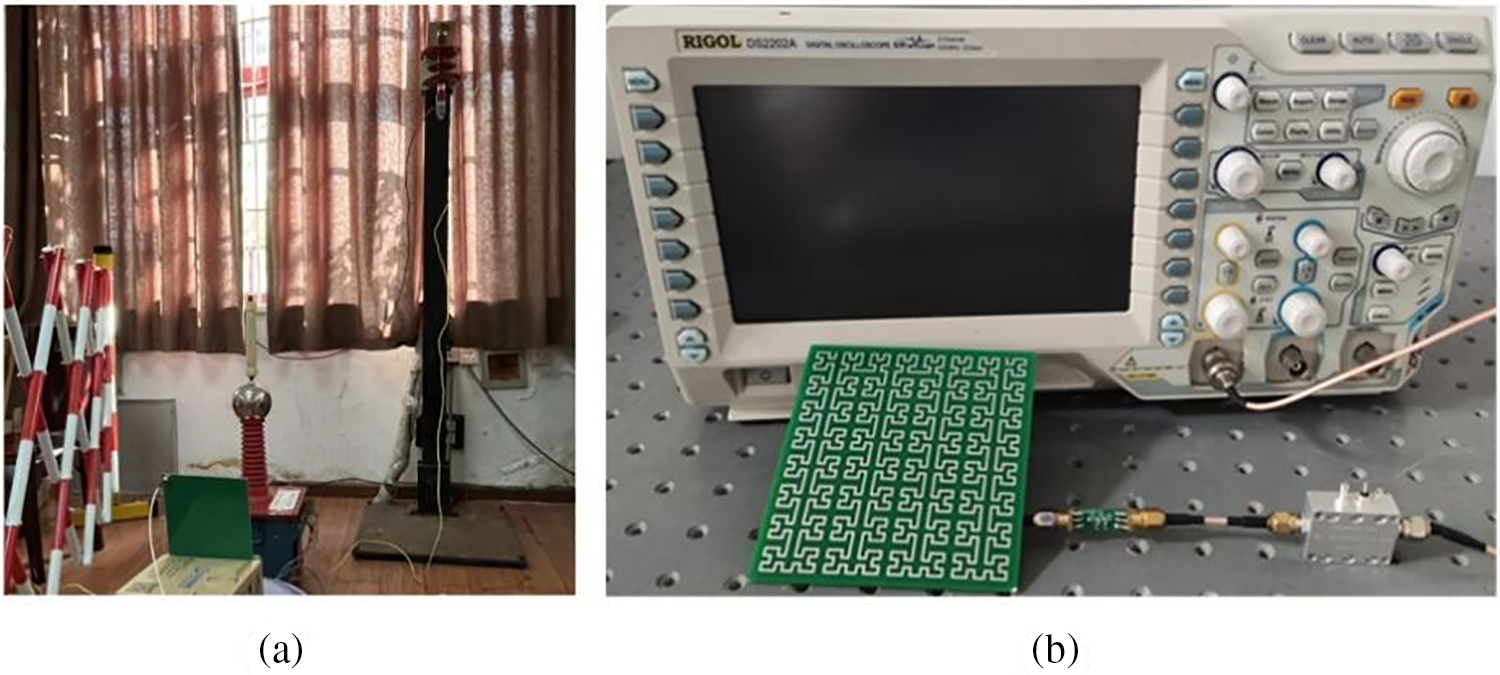
Figure 14: Images of the experimental platform: (a) PD signal generation component; (b) PD signal detection component
The time-domain and frequency-domain waveforms of the experimental ambient noise were tested in advance, as shown in Figs. 15a and 15b. The experiment was conducted as follows. The high voltage output of the transformer system was increased gradually. The composite insulator was subject to PD when the transformer output reached about 35 kV, at which point the insulator emitted a distinct crackling sound. The center of the 2nd-order, 4-layer SHU antenna was then placed a distance D of 1, 2, 5, and 8 m from the axis of the composite insulator, and the received PD signals were recorded by the oscilloscope. The time-domain waveforms captured by the prototype SHU antenna positioned at D values of 1–8 m is presented in Fig. 16, respectively, and the corresponding amplitudes of the detected PD signals are listed in Table 4. In this experiment, the classical 4th-order Hilbert fractal antenna and SHU antenna [15] are selected to detect the localized discharge signal at a detection distance of 5 m. The time-domain and frequency-domain waveform diagrams of the detected signals are shown in Fig. 17, respectively. Figs. 17a–17c show the time domain waveforms of the two antennas, respectively, in which the strength of the detected signals from the SHU antenna is significantly larger than that of the Hilbert fractal antenna. Figs. 17b and 17d show the frequency domain waveforms of the two antennas, respectively, in which the localized discharge signals detected by the antenna are mainly distributed from 0.3 to 1.5 GHz.
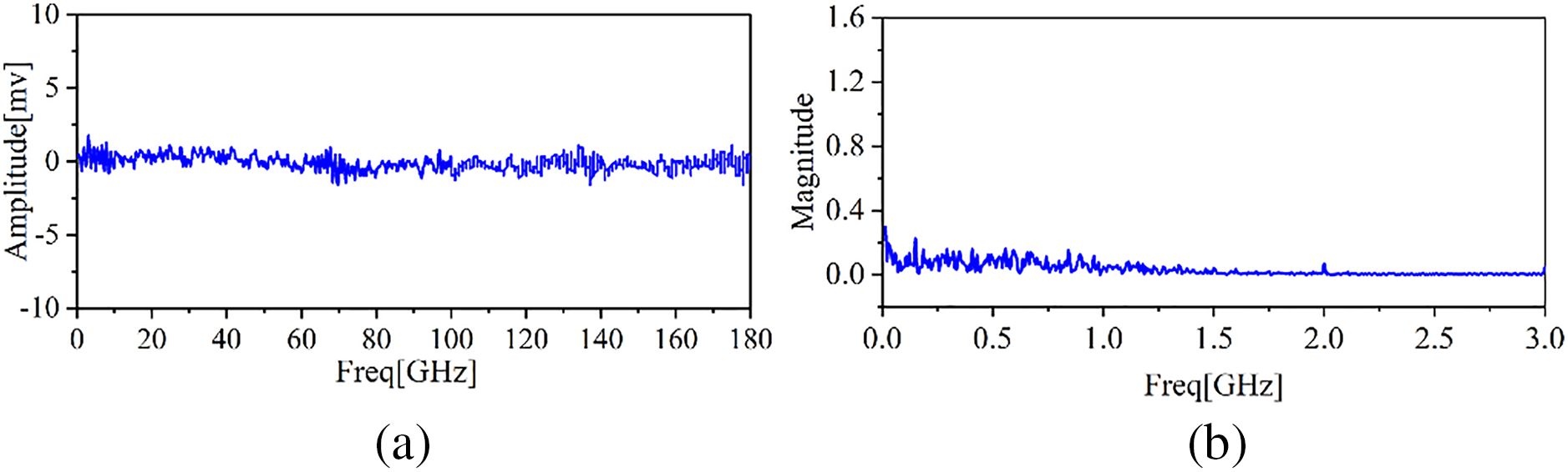
Figure 15: Experimental environmental noise: (a) The time-domain waveform; (b) The frequency-domain waveform
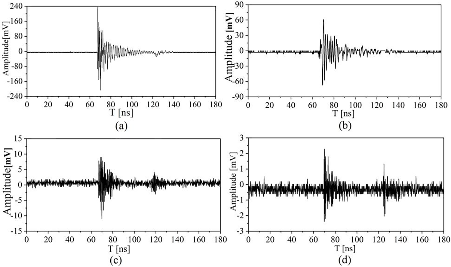
Figure 16: Time-domain waveforms of PD signals captured by the 2nd-order, 4-layer SHU antenna positioned at different detection distances D from the PD source: (a) D = 1 m; (b) D = 2 m; (c) D = 5 m; (d) D = 8 m
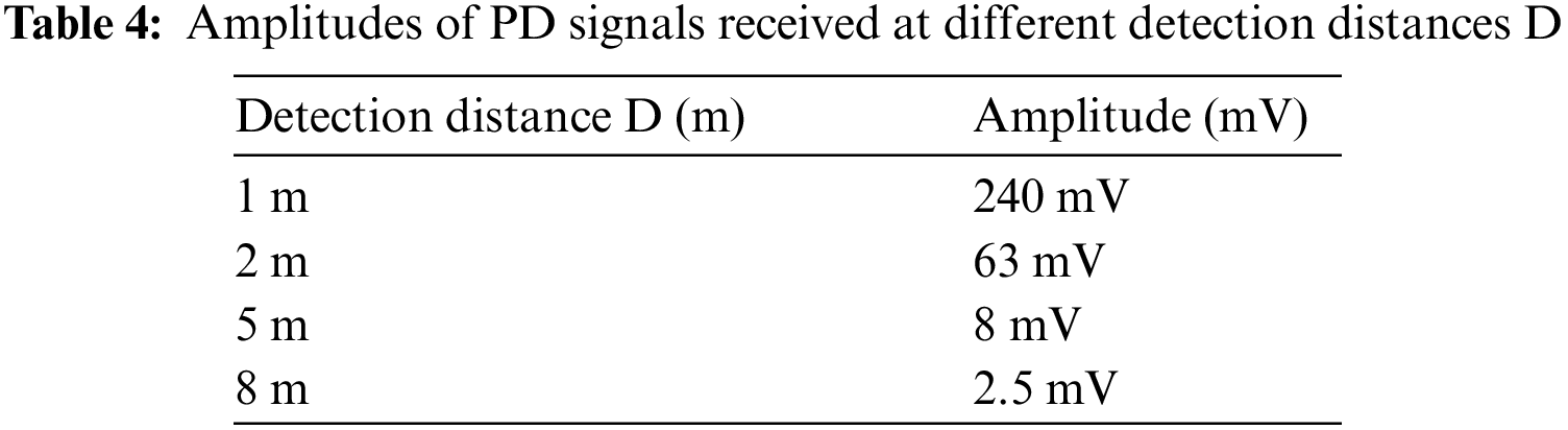
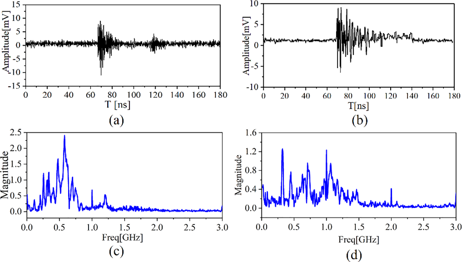
Figure 17: (a) The time-domain waveform diagram of 2nd-order, 4-layer SHU antenna; (b) The frequency-domain waveform diagram of 2nd-order, 4-layer SHU antenna; (c) The time-domain waveform diagram of the classical 4th-order Hilbert fractal antenna; (d) The frequency-domain waveform diagram of the classical 4th-order Hilbert fractal antenna
The present work addressed the issues associated with current antennas employed for detecting the PD signals of electric power equipment by proposing a serpentine-Hilbert unit (SHU) antenna design that incorporates Hilbert fractal units within a multiple-layer serpentine arrangement to obtain a miniature antenna with a fixed dimensions of 100 mm × 100 mm × 1.6 mm. The SHU antenna design was optimized to obtain as large a detection bandwidth share for which VSWR < 2 as possible within the frequency range 0.3 to 3 GHz. The optimization process yielded a 2nd-order, 4-layer SHU structure with a fractal unit spacing of 3.0 mm, which was demonstrated to achieve a detection bandwidth that is approximately 97.3% of the UHF frequency range based on computations. The results of experimental tests conducted with a prototype antenna demonstrated that the proposed design outputs a signal amplitude of 2.5 mV when positioned a distance of 8 m from the signal source, which is sufficient to detect a PD signal. The proposed antenna design offers a number of advantages, in that it combines the space filling characteristics of Hilbert fractal antennas with the flexibility of serpentine antenna forms. As a result, the performance of the SHU antenna can be modified by adjusting well-defined structural parameters. Hence, the antenna can be optimized from a number of different perspectives in addition to the detection bandwidth. In the future, we will seek to validate the performance of the proposed SHU antenna in various types of power equipment.
Acknowledgement: This work was funded by the China Southern Power Grid Limited Technology Project.
Funding Statement: The authors received no specific funding for this study.
Author Contributions: The authors confirm contribution to the paper as follows: study conception and design: X. Lin, Q. Wang, J. Fang; data collection: M. Zhang, K. Yin; analysis and interpretation of results: X. Lin, J. Fang, K. Yi; draft manuscript preparation: Yan Tian. All authors reviewed the results and approved the final version of the manuscript.
Availability of Data and Materials: All data in the article can be obtained by sending an email to the author. At the same time, the vast majority of data has been clearly provided in the article.
Conflicts of Interest: The authors declare that they have no conflicts of interest to report regarding the present study.
References
1. Guo, Z., Huang, A. Q., Hebner, R. E., Montanari, G. C., Feng, X. (2022). Characterization of partial discharges in high-frequency transformer under PWM pulses. IEEE Transactions on Power Electronics, 37, 11199–11208. [Google Scholar]
2. Machado, G. D. O., Gomes, L. C., da Silveira, A. W. F. V., Tavares, C. E., de Andrade, D. A. (2022). Impacts of harmonic voltage distortions on the dynamic behavior and the PRPD patterns of partial discharges in an air cavity inside a solid dielectric material. Energies, 15, 2650. [Google Scholar]
3. Sikorski, W., Wielewski, A. (2023). Low-cost online partial discharge monitoring system for power transformers. Sensors, 23, 3405. [Google Scholar] [PubMed]
4. Stone, G. C. (2005). Partial discharge diagnostics and electrical equipment insulation condition assessment. IEEE Transactions on Dielectrics and Electrical, 12, 891–904. [Google Scholar]
5. Srinangyam, C., Pannil, P., Nimsanong, P., Chuayin, C., Thungsook, K. et al. (2022). Online PD measurement by detecting the pulsed compensating current in high voltage equipment. 2022 8th International Conference on Engineering, Applied Sciences, and Technology (ICEAST), pp. 54–57. Chiang Mai, Thailand. [Google Scholar]
6. Skubis, J., Kozioł, M. (2021). Assessment of partial discharges in the air by application of corona camera. Applied Science, 11, 8595. [Google Scholar]
7. Ren, M., Song, B., Zhuang, T., Yang, S. (2018). Optical partial discharge diagnostic in SF6 gas insulated system via multi-spectral detection. ISA Transactions, 75, 247–257. [Google Scholar] [PubMed]
8. Wang, G., Jo, H. E., Kim, S. J., Kim, S. W., Kil, G. S. (2016). Measurement and analysis of partial discharges in SF6 gas under HVDC. Measurement, 91, 351–359. [Google Scholar]
9. Ji, S., Wang, Y., Li, J., Meng, Y., Liang, N. et al. (2015). Review of UHF antenna sensor for detecting partial discharge in GIS. High Voltage, 51, 163–172 (In Chinese). [Google Scholar]
10. Hu, X., Zhang, G., Liu, X., Chen, K., Zhang, X. (2023). Design of high-sensitivity flexible low-profile spiral antenna sensor for GIS built-in PD detection. Sensors, 23, 4722. [Google Scholar] [PubMed]
11. Ariannik, M., Azirani, M. A., Werle, P., Azirani, A. A. (2019). UHF measurement in power transformers: An algorithm to optimize accuracy of arrival time detection and PD localization. IEEE Transaction on Power Delivery, 34, 1530–1539. [Google Scholar]
12. Qi, Y., Fan, Y., Bing, G., Jia, R., Sen, W. et al. (2019). Design of ultra-wide band metal-mountable antenna for UHF partial discharge detection. IEEE Access, 7, 60163–60170. [Google Scholar]
13. Wang, P., Ma, S., Akram, S., Zhou, K., Chen, Y. et al. (2020). Design of archimedes spiral antenna to optimize for partial discharge detection of inverter fed motor insulation. IEEE Access, 8, 193202–193213. [Google Scholar]
14. Ghanakota, K. C., Yadam, Y. R., Ramanujan, S., Vishnu Prasad, V. J., Arunachalam, K. (2022). Study of ultra high frequency measurement techniques for online monitoring of partial discharges in high voltage systems. IEEE Sensor Journal, 22, 11698–11709. [Google Scholar]
15. Li, J., Jiang, T. Y., Cheng, C. K., Wang, C. S. (2013). Hilbert fractal antenna for UHF detection of partial discharges in transformers. IEEE Transactions on Dielectrics and Electrical Insulation, 20, 2017–2025. [Google Scholar]
16. Wu, Y., Zhang, H., Wu, J., Zhang, G. (2022). Experimental study on the propagation characteristics of UHF partial discharge signals in linear and L-shaped structures for 252 kV GIS. High Voltage, 58, 223–228 (In Chinese). [Google Scholar]
17. Tian, J., Zhang, G., Ming, C., He, L., Liu, Y. et al. (2022). Design of a flexible UHF hilbert antenna for partial discharge detection in gas-insulated switchgear. IEEE Antennas Wireless and Propagation Letter, 1–5. [Google Scholar]
18. Li, J., Wang, P., Jiang, T. Y., Bao, L. W., He, Z. M. (2013). UHF stacked hilbert antenna array for partial discharge detection. IEEE Transactions on Antennas and Propagation, 61, 5798–5801. [Google Scholar]
19. Yin, C., Wei, H., Xia, Y., Hei, G., Zhang, Y. (2018). Hilbert fractal antenna design for detecting corona discharge on transmission lines. 10th International Conference on Communications, Circuits and Systems (ICCCAS), pp. 172–175. Chengdu, China. [Google Scholar]
20. Xu, Z., Hei, G. (2021). Rectangular spiral antenna with a hilbert unit for detecting corona discharge in overhead lines. IEEE Sensor Journal, 21, 930–936. [Google Scholar]
21. Liu, N., Sheng, X., Zhao, X. (2020). Design of dual-polarized frequency selective rasorber with two independent transmission windows using multi-resonators. IEEE Access, 8, 223723–223729. [Google Scholar]
Cite This Article
 Copyright © 2024 The Author(s). Published by Tech Science Press.
This work is licensed under a Creative Commons Attribution 4.0 International License , which permits unrestricted use, distribution, and reproduction in any medium, provided the original work is properly cited.
 Downloads
 Citation Tools