
 Submit a Paper
 Propose a Special lssue
 Open Access
ARTICLE

A Study of the Effect of the Miller Cycle on the Combustion of a Supercharged Marine Diesel Engine
Mechanical and Automotive Engineering School, Shanghai University of Engineering Science, Shanghai, 201600, China
* Corresponding Author: Cong Li. Email:
Energy Engineering 2024, 121(5), 1363-1380. https://doi.org/10.32604/ee.2024.046918
Received 19 October 2023; Accepted 28 December 2023; Issue published 30 April 2024
 View Full Text
 Download PDF
Abstract
The Miller cycle is a program that effectively reduces NOx emissions from marine diesel engines by lowering the maximum combustion temperature in the cylinder, thereby reducing NOx emissions. To effectively investigate the impact of Miller cycle optimum combustion performance and emission capability under high load conditions, this study will perform a one-dimensional simulation of the performance of a marine diesel engine, as well as a three-dimensional simulation of the combustion in the cylinder. A 6-cylinder four-stroke single-stage supercharged diesel engine is taken as the research object. The chassis dynamometer and other related equipment are used to build the test system, carry out the diesel engine bench test, and collect experimental data. The simulation results are compared with the test results, and the error is less than 5%. In this study, the authors will use simulation software to simulate several Miller cycle scenarios designed for early inlet valve closure and analyze the impact of the Miller cycle on combustion and emissions at 100% load conditions. By comparing the flow field distribution of the engine at 1500 r/min condition, it was found that proper EIVC can prolong the ignition latency period and homogeneous fuel-air mixture combustion acceleration, but it can reduce pressure and temperature within the piston chamber and NOx emission. However, the Miller cycle reduces end-of-compression temperatures, which increases combustion duration and exhaust temperatures, making it difficult to improve fuel economy at the optimum fuel consumption point, and closing the intake valves prematurely leads to excessive fuel expenditure. Furthermore, temperature and heat release rate within the piston chamber, NOx, and SOOT generation were significantly enhanced.Keywords
Nomenclature
| BSFC | Brake-specific fuel consumption |
| EIVC | Early Intake valve closure |
| E3 | Four kinds of loads, 100%, 75%, 50%, 25% |
| LIVC | Lately Intake valve closure |
| IVCT | Intake valve closing time |
| PM | Particulate matter |
| VGT | Variable geometry turbocharger |
| HDDI | Heavy-duty direct injection |
| SAGE | Solver combustion model |
| TDC | Top dead center |
| IC | Internal combustion |
| e.g. | |
| Mass of work mass in the cylinder (kg) | |
| Internal energy of the work mass in the cylinder (J/(kg·mol)) | |
| Work pressure within cylinder (Pa) | |
| Operating volume of piston chamber (L) | |
| Exothermic heat of combustion of the fuel (kJ) | |
| Heat loss through the system boundary (kJ) | |
| Crankshaft angle of rotation | |
| Enthalpy of the exhaust gas from the discharge cylinder (J/(kg·mol)) | |
| Mass flow rate of the exhaust gas from the discharge cylinder (kg) | |
| Mass of gas flowing into the cylinder (kg) | |
| Mass of gas flowing out of the cylinder (kg) | |
| Enthalpy of the gas flowing out of the cylinder (kJ/(kg·mol)) | |
| Heat of vaporization of the fuel (kJ) | |
| Heat of vaporization coefficient of cylinder filling | |
| Mass of fuel evaporated (kg) | |
| Fluid velocity component in the j-direction | |
| Turbulent kinematic viscosity coefficient | |
| Kinematic viscosity of the fluid | |
| Dissipation rate | |
| Specific dissipation rate | |
With the development of the times and the automobile industry, all kinds of energy in China are gradually in short supply, and automobiles have become a major contributor to energy consumption and pollution emissions [1–4]. As a result, the development of energy-saving technologies and the reduction of pollutant emissions are receiving increasing attention. In the internal combustion engine, the diesel engine has high power, strong dynamics, and small size characteristics, in the major fields are widely used [5]. In the face of stringent requirements for dynamics as well as emission performance, a variety of new technologies such as exhaust gas recirculation, Miller cycle, and high-pressure common rail are utilized in diesel engines. The Miller cycle is one of the hot research topics due to its ability to reduce NOx [6–8].
The Miller cycle realized by EIVC, also improves combustion efficiency [9]. The following Fig. 1 gives the operation of the Miller cycle in the ideal state of a diesel engine. During the intake stroke phase, the intake valve closes before the piston reaches the bottom (at point 6), and the cylinder gas expands to point 7. During the compression stroke phase, the gas is compressed from point 7 to point 5, however, only 6
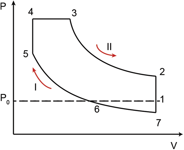
Figure 1: Miller cycle of diesel
There have been many studies on how the Miller cycle affects diesel engine emissions and combustion. Jahanbakhshi et al. [11] analyzed the thermodynamic process by changing the working fluid in the engine cylinder to become a mixed fuel based on the pressure cloud map, using bioethanol and diesel as liquid fuels mixed with air. Through research, it was found that when the peak compression ratio is low, the Miller cycle was on average 8% better than the Otto cycle when comparing the two cycles from the perspectives of output power and thermal efficiency. Wu et al. [12] carried out a practical test on how the Miller cycle coupled VGT affects burning, in order to study the impact of the Miller cycle on the combustion and emission performance of diesel engines. The experimental results showed that Miller cycle coupled VGT can effectively reduce the peak NOx emissions and reduce the generation by up to 10%. However, the adverse impact on diesel engines was a 10% increase in peak SOOT emissions. Ghazi Nezami et al. [13] conducted an experimental study to investigate the effects of changes in inlet valve early closure angle on combustion, emission performance, and thermal efficiency in highly intensified diesel engines. The research results show that the maximum pressure and exhaust temperature of the cylinder are greatly influenced by the Miller cycle but have little impact on the generation of BSFC and particulate matter (PM). At the same time, in the case of the high overall efficiency of turbochargers, compared with traditional intake valve curves, using the Miller cycle can reduce cylinder peak pressure and increase exhaust temperature, but it will not affect the emissions of BSFC, nitrogen oxides (NOx), or particulate matter (PM). Guan et al. [14] analyzed the effect of the delayed intake valve closure (LIVC) Miller cycle on the performance and exhaust emissions of a single-cylinder diesel engine. Additionally, they studied the performance of diesel engines by coupling technologies such as exhaust gas recirculation (EGR) and delayed injection. The research results show that when the intake valve is closed at IVCT 265°CA, NOx emissions are reduced by more than 20%. Jiang et al. [15] developed a simulation model using the simulation software GT-POWER and proposed a biodiesel-based Miller cycle. The results indicate that the biodiesel can improve emission performance. As a result, when the valve was closed 30°CA in advance. The biodiesel B10 scheme showed the best emission performance for diesel engines. Roper et al. [16] applied CFD software Ricardo WAVE for validation analog of the operating process of diesel engine. The results show reductions in NOx, CO, HC, and particulate emissions by adopting the Miller cycle strategy, as well as by changing fuel to lower carbon fuel. Georgiou et al. [17] studied a four-stroke 6-cylinder diesel engine in stages, initially using the diesel engine as the original engine to obtain a large amount of data, to prepare the components for simulation modeling in the subsequent stage. The purpose of the model simulation phase is to compare the best Miller cycle strategies that bring higher performance and lower pollutant emissions to diesel engines. According to the results of the study, the power and torque of the engine have increased slightly, around 5.5%. However, the impact on emissions is huge, with NOx emissions reduced by 30.2%. Cengiz et al. [18] and Georgiou et al. [17] investigated the impact of early exhaust valve closure on fuel consumption control by using professional CFD simulation software to address the issue of combustion focusing close to TDC. Research has shown that the EIVC partial strategy can bring the combustion center of gravity closer to TDC 5-10°CA. Meanwhile, EIVC reduces NOx emissions by 30%. Wen et al. [19] compared the effects of the Miller cycle on fuel consumption and indicated the thermal efficiency of turbocharged diesel engines achieved by late and early intake valve closure (LIVC & EIVC) through experiments. The results show that the loss generated by the Miller cycle is only 2.55%. Wei et al. [20] utilized the CFD software AVL-FIRE to simulate the working process in the cylinder of a diesel engine under 25% and 50% load conditions. The results show a 17.8% reduction in NO emissions at a load of 50% under propeller operating conditions. Additionally, NO emissions are reduced by 14.9% at a load of 25%. When the intake valve closes too early, the heat release rate curve steepens quickly, along with an increase in NO production. Zhang et al. [21] used CFD software AVL-FIRE to construct an engine model to analyze the velocity distribution, temperature distribution, and pressure distribution during the combustion process in the cylinder. This provides a basis for optimizing and improving the structure of the combustion chamber. Sjöblom et al. [22] investigated the effects of different injection times and pressures on the combustion and emission characteristics of diesel engines when coupled with the post-Miller cycle. Sun et al. [23] utilized the fine chemical solver combustion model (SAGE) in the CFD software CONVERGE. The results indicate that the SAGE model has a smaller error between the calculated results and experimental data compared to other models.
However, while the Miller cycle has been shown to be effective in reducing NOx emissions by lowering the maximum combustion temperature, its effect on other parameters such as exhaust gas temperature and pollutant generation remains to be analyzed in depth. There is a lack of comprehensive investigation on the effect of the Miller cycle on the combustion performance and emission characteristics of marine diesel engines because the mechanism of SOOT generation is relatively complex and highly dependent on the combustion conditions. In addition, the formation and emission of SOOT usually occur inside the combustion chamber and in the exhaust system, which poses a challenge for experimental measurements and sampling. Therefore, relatively few studies have been conducted on the generation and in-cylinder distribution of SOOT and NOx emissions.
There are relatively few studies that utilize GT-POWER and CONVERGE to investigate the effects of the Miller cycle on the performance of marine diesel engines as well as in-cylinder combustion and emission performance [24]. Numerical simulations of the in-cylinder operating processes of a marine compression-ignition engine were conducted utilizing the three-dimensional CFD simulation software, CONVERGE. The influence of the Miller cycle on the combustion and emission performance of the diesel engine was discussed. The objective of this study is to investigate the impact of the Miller cycle on the combustion process and emissions of diesel engines, to comply with applicable standards. To achieve this, a one-dimensional GT-POWER simulation and a three-dimensional CONVERGE simulation model will be developed using a test system of a marine six-cylinder turbocharged engine. The combustion model, turbulence model, spray model, and cylinder wall heat transfer model suitable for highly efficient direct injection diesel engine have been carefully chosen. Calibrated and validated the model in comparison with the experimental data. By utilizing the inlet and exhaust temperatures and pressures obtained from the one-dimensional model as the initial boundary conditions for the three-dimensional model, an investigation and comparison were conducted on the trends of average pressure, temperature, heat release rate, and emissions of diesel engine equipped with different EIVC strategies under full load conditions. The effect of the Miller cycle arrangement on the spatial distribution of parameters including combustion period, temperature, maximum pressure, SOOT, and NOx in the cylinder is analyzed.
2.1 Test Equipment and Engine Parameters
The test diesel engine used in this research is a quad-stroke inline engine with a six-cylinder configuration running on diesel fuel with an ω-shaped combustion chamber. The key engineering specifications of the diesel engine are presented in Table 1. The Solenoid-controlled fuel injection system with a common rail, which provides rail pressure of up to 180 MPa is the Bosch CRIN2-16. The rail pressure and injection timing are adjusted according to the speed, load, etc., allowing for complex injection patterns. Pressure measurement is done using sensors of the Kistler 4000 series. The dynamometer adopts the ECDM-72H dynamometer system from MAHA, Germany. The test system layout is shown in Fig. 2. A physical drawing of the bench test is shown in Fig. 3.
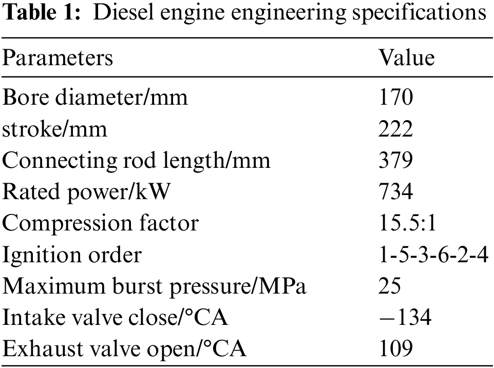
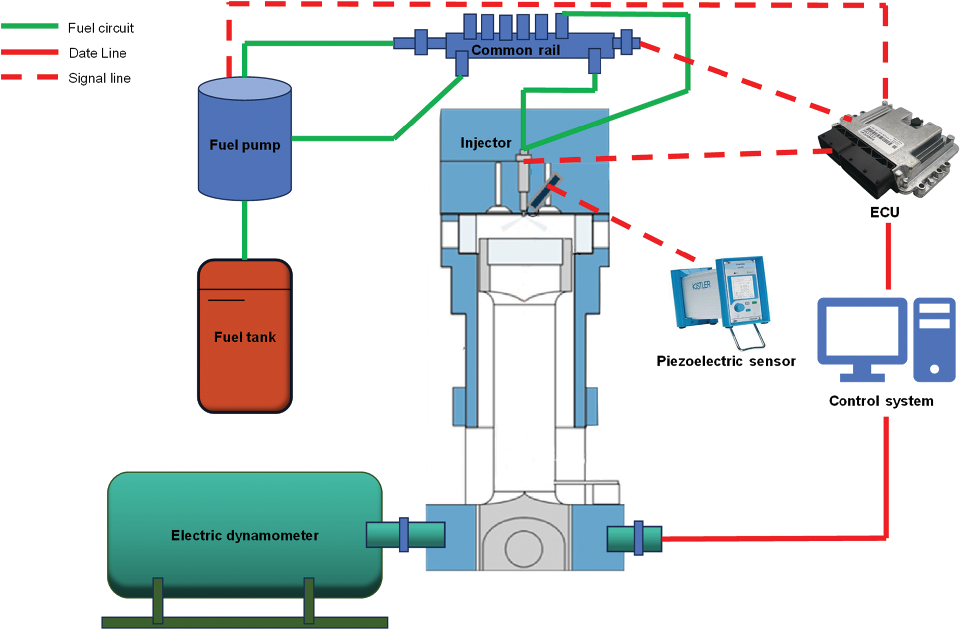
Figure 2: Schematic diagram of test stand
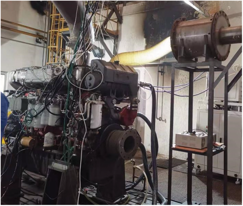
Figure 3: Diesel engine test stand
2.2 One-Dimensional Simulation Model of Engine Cylinder
In this paper, the diesel engine is a single-stage supercharged diesel engine, and the main components of the modular modeling include cylinders, crankcase, intake and exhaust pipes, turbocharger, intercooler, etc., and all the models of the modules are calibrated according to the actual dimensions provided by the test data [25]. The DIPulse predictive combustion model was selected, and a single-cylinder diesel engine model was built for simulation to calibrate this model. The combustion process in the cylinder is accurately reflected by the calibrated predictive combustion model, which is extended to the 6-cylinder diesel engine. Fig. 4 shows the construction of a complete model of a single-stage supercharged diesel engine. At the same time, the model was calibrated using diesel engine bench test data to check the Exactness of the numerical model.
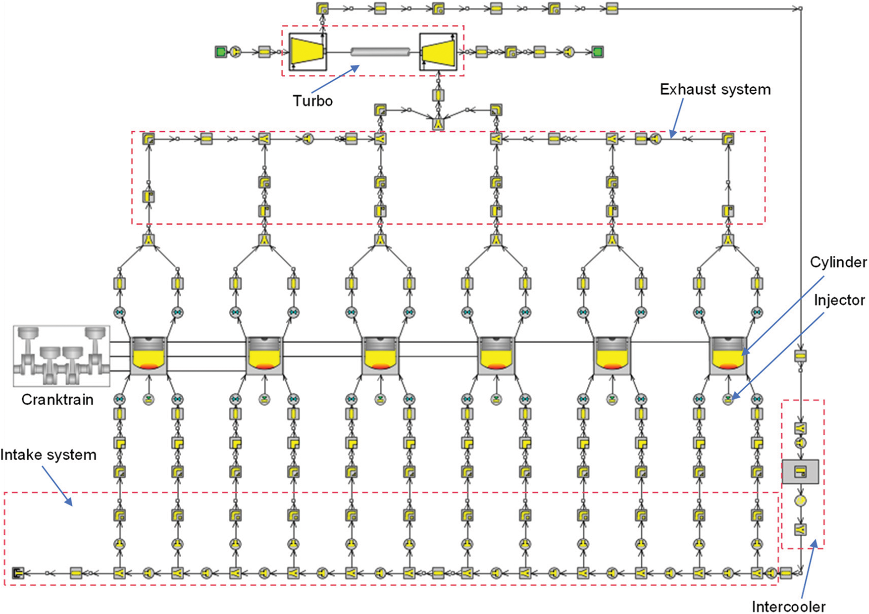
Figure 4: One-dimensional model of a diesel engine
As shown in Fig. 5, under each load condition of the original engine, the key performance parameters and state parameters match well with the original engine. The variance comparison of the measured and modeled data is within a 5% margin of error, which is within the permissible range. The findings demonstrate that the constructed GR-Power simulation model of the supercharged engine exhibits excellent accuracy. Therefore, this model can be effectively utilized for conducting simulation studies on the burning reaction in diesel engines.
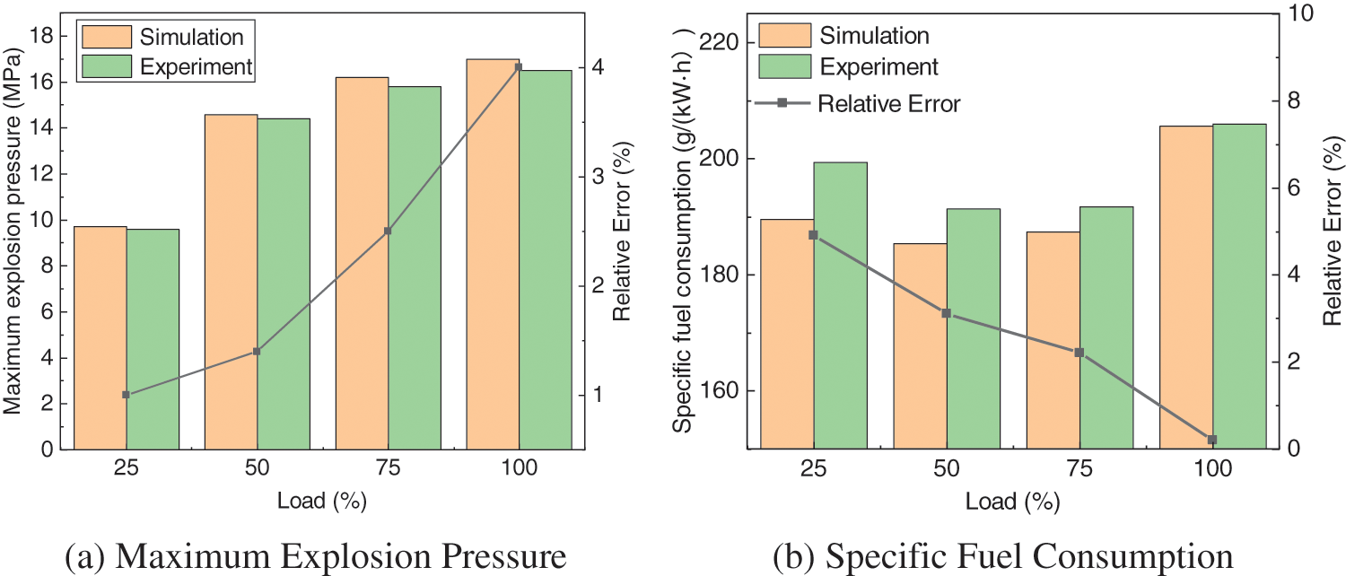
Figure 5: Comprehensive engine calibration outcomes
2.3 Three-Dimensional Numerical Model
Based on a 3D simulation model of a supercharged marine diesel engine, this paper presents its study and findings. Through using UG, the 3D geometric model is drawn and the geometric surface STL file is imported into the CONVERGE software, and the CONVERGE software incorporates an automated tool package for grid partitioning. The fuel sprayer is a nozzle equipped with 8 holes in the middle. To improve the calculation accuracy and save the model calculation time, only a 1/8 cylindrical physical model was used for the numerical analysis since the simulation model is a symmetric structure. Omit the intake and exhaust system, set the eddy coefficient and turbulence kinetic power when the intake valve is closed, and ignore the fluid movement in the air passage and the airflow velocity in the direction of piston motion. The simulation run started when the intake valve was closed and concluded when the exhaust valve was opened. As shown in Fig. 6, the mesh at the upper stop of the combustion chamber with a base mesh size of 3 mm.
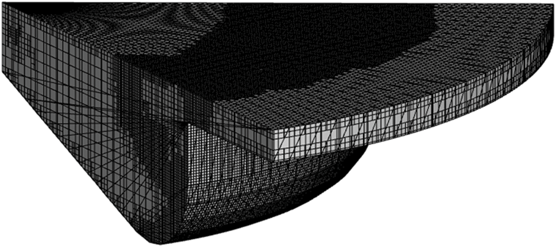
Figure 6: The mesh at the upper stop of the combustion chamber
The main computational models include turbulence models, combustion models, emission models (mainly NOx & SOOT), and spray models. The turbulence model takes into account the turbulent eddies, so the RNG k-
The flow of an air-fuel mixture within the combustor of a diesel engine can be described by working out the equations for mass, momentum, energy, and chemical components of the gas-phase fluid. The fuel combustion process in the cylinder involves complex processes such as physical and chemical reactions and heat transfer, but they all follow the principle of conservation of energy and mass. The law of sustainability of energy is calculated as shown below:
In an ideal state without leakage, the law of conservation of mass is:
where,
The RNG
where,
The specific reaction mechanisms for NOx emission modeling are as follows:
where, the reaction needs to be carried out under high temperature and oxygen-enriched conditions, and Eqs. (7) and (8) can only be carried out when the temperature within the piston chamber is greater than 1800 K for the reaction.
The full operating conditions of the diesel engine were simulated using the CFD model and the precision of the model was verified. Fig. 7 shows the simulated average pressure within the piston chamber compared to the test data. Fig. 8 shows a comparison of NOx emissions under E3 cyclic loading conditions. After comparing the curves, it is found that the gap and error between the simulated and experimental values of NOx discharge and average pressure within the cylinder are small. To quantitatively assess the accuracy of the simulation, the relative error between the simulated and experimental values was calculated using the following formula:
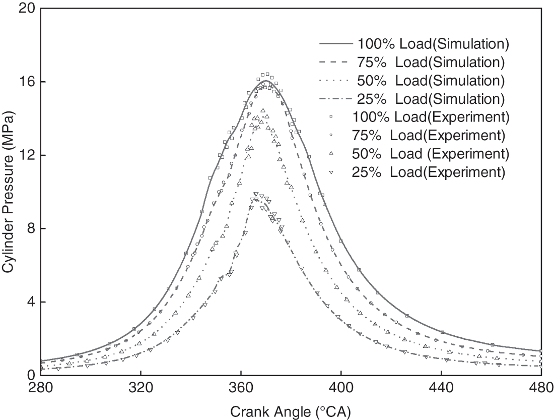
Figure 7: Comparison of experimental and simulated values of in-cylinder pressure
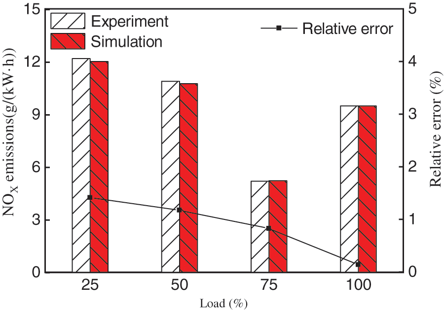
Figure 8: Comparison of experimental and simulated values of NOx emissions
As shown in Fig. 7, the maximum error between experimental and simulated values is about 4.5% at 25%, 50%, and 100% loading conditions and about 1.2% at 75% loading conditions. The average pressure within the cylinder obtained from the simulation closely matches the experimental results of the original engine under four operating conditions. Therefore, the relative error between the experimental and simulated data falls within an acceptable range. As shown in Fig. 8, all discrepancies fall within the targeted 2% threshold of the experimental data. So, the model exhibits the capability to accurately predict the NOx emissions. The simulation findings exhibit strong alignment with the in-cylinder combustion and NOx emission characteristics of the diesel engine, thereby demonstrating the reliability of the established model and the accuracy of the simulation model parameters.
3 Calculation Results and Discussion
3.1 Effect of the Miller Cycle on Cylinder Temperature and Pressure
The diesel engine model was simulated and analyzed under different strategies by setting the exhaust valve advance closure strategies for the original engine model at 100% load condition as IVC205, IVC185, IVC165, IVC145, and IVC125, respectively. As depicted in Fig. 9, the calculated pressures within the cylinder at different Miller cycles for the compression, combustion, and expansion stages of the cylinder at high load. During the compression phase, the cylinder pressure decreases with increasing EIVC. The intake volume stays the same, so the pressures in the cylinders are all lowered. As IVCT advances, the lag phase increases, and the time to ignition is delayed. Early closure of the inlet valve lowers the effective compression ratio. At the same time, it lowers the pressure of the piston when it reaches the top dead center, which increases the stagnation period and delays the moment of ignition accordingly.
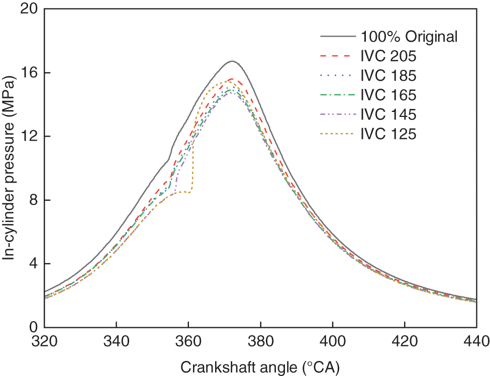
Figure 9: Mean pressure of engine cylinders as affected by miller cycle schemes
While in the combustion stage, the maximum point of pressure decreases significantly as the IVC is advanced. Peak pressures exceeding the tolerance limits of the engine block can significantly reduce engine life. However, the ratio of pressure elevation increases with IVCT and the moment of rapid pressure rise in the cylinder lags. The pressure profile inside the cylinder as depicted curve in Fig. 9 shows that when the IVCT is changed from IVCT of the original engine to IVC 145°CA. The maximum point of pressure
As shown in Fig. 10, under maximum load conditions, the Miller cycle has an impact on the mean temperature within the cylinder. The mean temperature within the cylinder follows a consistent trend to that of the mean pressure. The earlier the IVCT is, the lower the average temperature is. After ignition, the curve of average temperature is almost the same as that of the test engine, and they demonstrate a consistent correlation in their trends. The onset of the mean temperature rise was delayed, and the peak of the mean temperature was closer. When the IVCT is advanced from IVCT of the original engine to IVC125 the average temperature peak in the cylinder compared to the original machine is reduced by about 200 K. When the IVCT is advanced from IVC165 to IVC125 the IVCT is advanced to just before the lower stopping point, the equivalent compression factor is decreased, and in the process of the piston traveling downward the in-cylinder temperature is lowered, the stagnation period is prolonged and the combustion rate becomes slower.
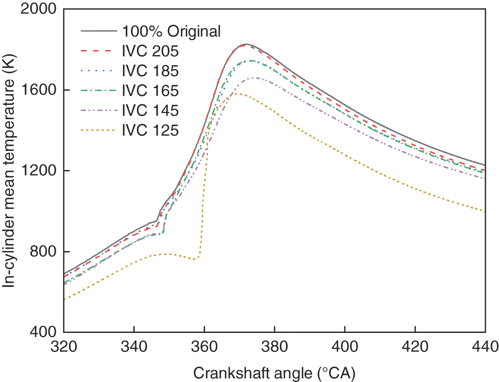
Figure 10: Average temperature of engine cylinders as affected by miller cycle schemes
Fig. 11 illustrates the variation rule of the in-cylinder temperature field with the advancement of the intake valve closing angle under high load conditions. As IVCT is advanced, the upper stop temperature decreases. Due to the reduced temperature within the cylinder, the combustion start point lags, and the primary areas of high-temperature concentrate are in the combustion chamber pit and near the cylinder wall. The reduced temperature region inside the cylinder is gathered in the cylinder center shaft. Because of the early closure of the intake valve, when the IVCT is advanced to the lower stop, the local oil and gas mixing is uniform. The combustion process is moderated. The greatest combustion temperature is reduced. When the IVCT is advanced to IVC125, the cylinder temperatures are lower. And IVC205 and IVC165 already have larger high-temperature areas. Maximum temperatures of 2800 K or more can be reached in all cases when the piston position is below 10°CA after TDC. Scheme IVC125 has the biggest area of high temperature, which is caused by late ignition and the cumulation of a substantial quantity of combustible blend. Therefore, IVC125 has the highest combustion exothermic rate of all the options. When the piston position is at 15°CA ATDC and 20°CA after TDC, the main combustion area of Scheme IVC205 and Scheme IVC165 is concentrated in the upper part of the combustion chamber space, which is beneficial to improving the air utilization efficiency. In contrast, the combustion region for Scheme IVC125 is within the combustion chamber pit, resulting in lower air utilization efficiency.
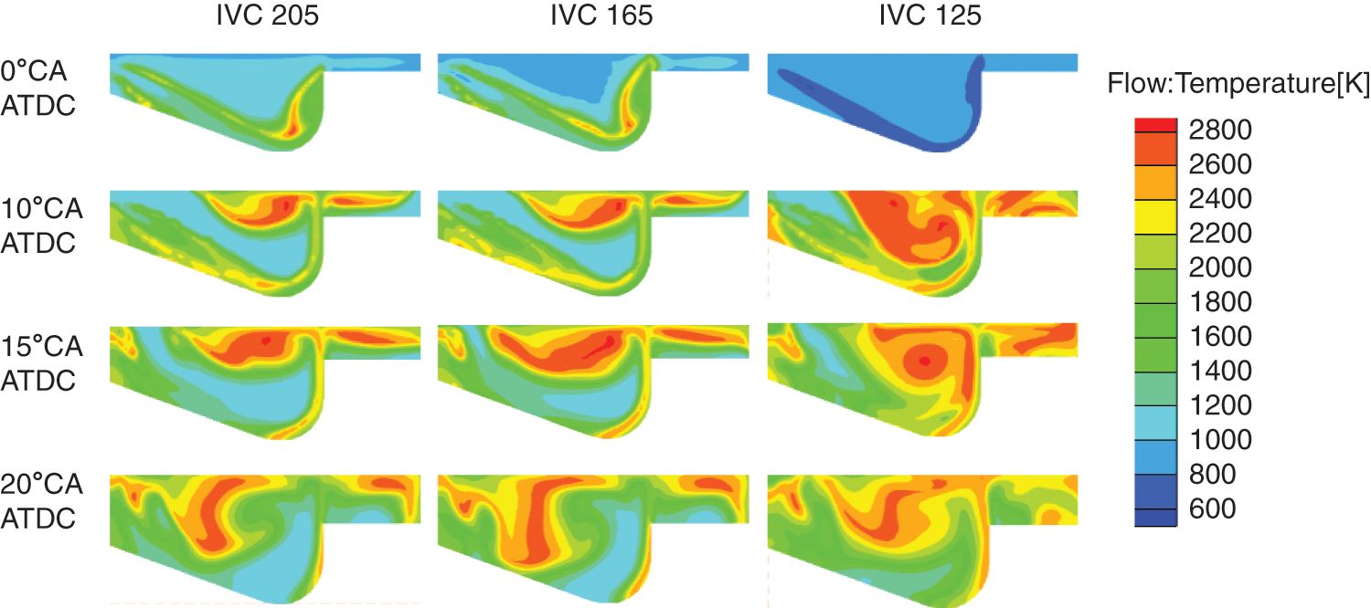
Figure 11: The spatial temperature dispersions within the cylinder miller cycle schemes
3.2 Effect of the Miller Cycle on Combustion Performance
As depicted in Fig. 12, the temperature within the cylinder near TDC is influenced by the Miller cycle. Both temperature and pressure following the compression stroke are critical factors that affect the ignition delay. The increase in ignition delay time is notable. With the further drop in cylinder temperature, the ignition delay time increases even faster. At longer ignition delays, more mixture is formed, accelerating premixed burning and enhancing the rate of heat output. The variation of exothermic rate at dissimilar Miller cycles is shown in Fig. 12. Under maximum load conditions, combustion starts to be postponed and the maximum value of premixed combustion increases sharply with increasing EIVC. The heat release rate of Scheme IVC125 has only one peak, which is significantly greater than the value observed in the original engine and five times higher than that of Scheme IVC145. This effect can be attributed to a lower effective compression ratio, lower temperatures and pressures within the cylinder in the phase of compression, a longer stagnation period, and more air-fuel blending time, leading to very rapid combustion and very short exothermic durations at ignition.
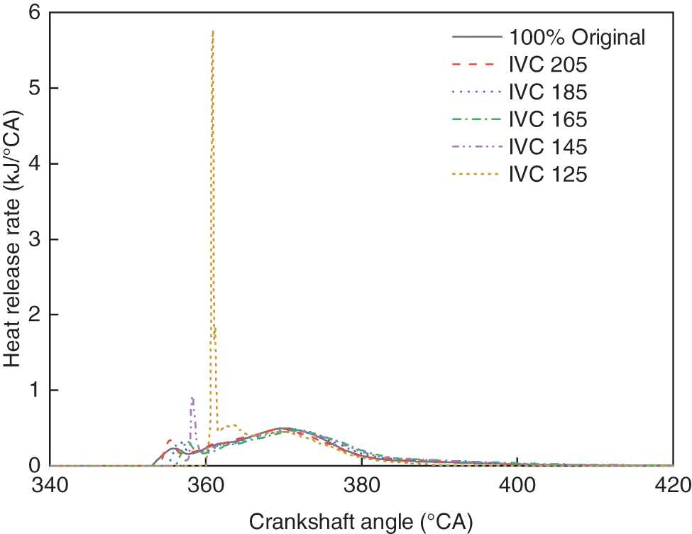
Figure 12: The heat release rate of engine cylinders as affected by miller cycle schemes
3.3 Effect of the Miller Cycle on Emission Performance
NOx is an important pollutant in diesel engines. Due to the intense heat within the combustor, NO is an essential component of NOx. The dominant reaction involved in the formation of NO can be reversed, according to the extended Zeldovich mechanism [34]. Thermal NO is produced within the combustor as a result of chemical interactions between O and N atoms. This reaction is a primary contributor to NO production in the combustor, particularly under high-temperature conditions. N elements are also present within the cylinder. Concurrently, NO is generated with oxygen during combustion through nitrogen-containing or organic compounds. Eqs. (7)–(9) demonstrate the quantity of NO produced in the mixture.
Fig. 13 shows the dispersion of NOx formation within the Miller cycle diesel engine cylinder operating at maximum load. This indicates that the formation of NOx within the piston chamber is strongly connected to the temperature field. At 0°ATDC, strategies IVC205 through IVC165 produce only a small amount of NOx, while strategy IVC125 produces only a very small amount of NOx due to the late ignition and low in-cylinder temperatures. At 10°ATDC, Scheme IVC125 has a higher NOx mass fraction than the other two schemes due to the sharp increase in-cylinder temperature. NOx production was reduced for each intake valve closure strategy as the intake valve closure time IVCT was advanced, but strategies IVC145 and IVC125 had higher NOx mass fractions than the other schemes at this time due to the intense combustion in the cylinder. At 20°ATDC, all three IVC scenarios produce large amounts of NOx due to the intense combustion within the piston chamber. The weight ratio of NOx decreases with advancing IVCT. However, there is a marginal rise in the weight ratio of NOx produced in Scheme IVC125. Premature closure of the intake valves under high load conditions leads to an increase in NOx production. Under high load conditions, NOx mass percent decreases as the IVCT is advanced, but premature IVCT causes an increase in NOx production.
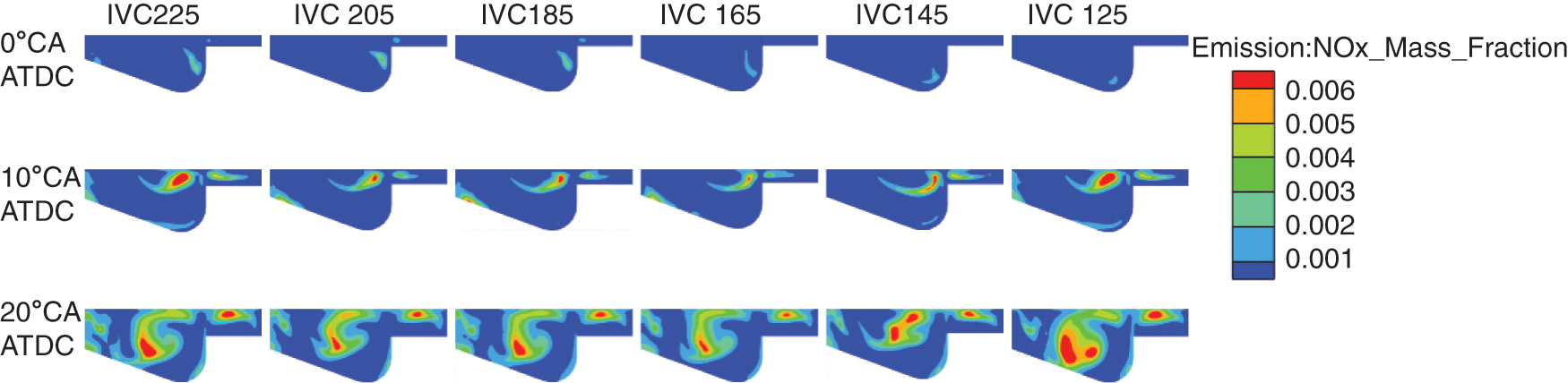
Figure 13: The spatial NOx dispersions within the cylinder miller cycle schemes
Fig. 14 shows SOOT distribution in the cylinder under full load conditions of the Miller cycle. SOOT is primarily accumulated in the central area of the oil slick during the early period of SOOT formation because the center of the oil slick belongs to an anoxic region. With subsequent diffusion and the mixing of oil and gas, combustion predominantly occurs at the core of the combustor and in the pits. In these regions, oxygen is rapidly consumed, giving rise to high-temperature anoxic zones. Inadequate combustion leads to the production and accumulation of SOOT within the pits of the combustor. As shown in Fig. 14, combustion primarily takes place near the bottom of the combustor crater, causing a decrease in oxygen concentration and the formation of a high-temperature anoxic zone. SOOT is generated in the pit zone of the combustor, with the majority accumulating at the bottom of the pit. Conversely, the lower combustion temperature and higher oxygen concentration in the center of the combustor create a low-temperature, oxygen-enriched area, which is unfavorable for SOOT formation. Simultaneously, the combustion process involves low-temperature combustion with the advancement of IVCT. The combustion temperature in the cylinder decreases significantly. The dispersion of the high-temperature region decreases substantially, and the low-temperature region increases gradually. Therefore, the conditions of SOOT formation are destroyed, and the amount of SOOT formation is decreased. SOOT emission is significantly decreased. Compared to the stock intake valve closure strategy, the SOOT generation under the intake valve advance closure scenario with the piston at the top stop is significantly lower, and even the IVC125 scenario does not generate SOOT at this time because it has not yet ignited. When the piston is at 20°CA after the top stop, SOOT distribution in scenario IVC185 is the least, and compared to IVC185, the SOOT generation in scenarios A slight increase in SOOT generation is evident in IVC165, IVC145, and IVC125, which may be due to the continued reduction in intake air volume.
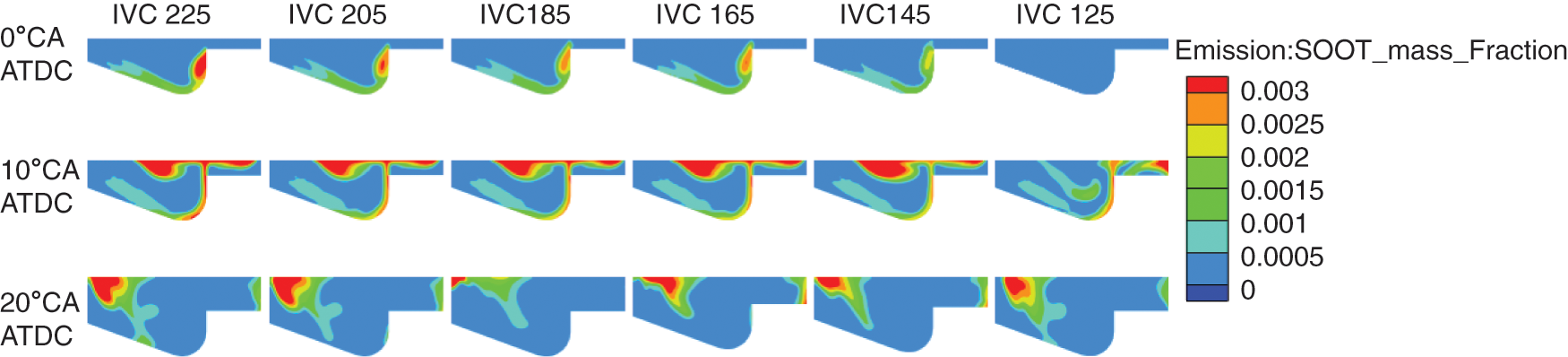
Figure 14: The spatial SOOT dispersions within the cylinder miller cycle schemes
With global warming and energy shortage, build a green and low-carbon circular economic system, improving the efficiency of energy utilization, and putting forward higher requirements for fuel consumption and pollutant emission of internal combustion engines. Therefore, the impact of different Miller cycle schemes on engine capability, in-cylinder burning, and discharge at 100% load was analyzed using a three-dimensional CFD method. The study’s results were discussed in detail and the subsequent findings resulted from the analysis.
1) The simulation model in this study was developed using dedicated CFD software., and the model is calibrated by experimental data. The findings indicate that the Miller cycle effectively reduces the pressure and temperature within the piston chamber nearing the end of compression. But when using the IVC125 scheme, the in-cylinder pressure peak is very high.
2) Because of lower effective compression ratios, lower temperatures, and pressures within the piston chamber during compression, along with extended stagnation periods and increased fuel-air mixing time, combustion occurs very rapidly with short exothermic durations at ignition. At 100% load, combustion initiation is delayed, and the peak of pre-mixed burning increases dramatically with increasing EIVC.
3) At 100% load, the Miller cycle shows a decrease in NOx generation at constant intake pressure, but too early intake valve advance leads to an increase in NOx generation, which is lowest when using strategy IVC165. As the intake valve closure time IVCT is advanced, the combustion process slows down, the combustion temperature decreases, the temperature field within the piston chamber drops substantially, and the in-cylinder oil-gas mixing becomes more homogeneous, leading to a significant decrease in the in-cylinder soot generation. However, the inlet valve is closed too early resulting in too little intake air, which in turn causes SOOT generation to increase in IVC165. Considering both NOx and SOOT emissions, the selection of the inlet valve closing strategy between IVC185 and IVC165 gives the best emission performance of the diesel engine.
Acknowledgement: The authors extend their sincere gratitude to the team. Without their assistance and encouragement, this research would not have been completed.
Funding Statement: This research was funded by the National Natural Science Foundation of China under Grant No. 51505275.
Author Contributions: The authors confirm contribution to the paper as follows: study conception and design: Lingjie Zhao, Cong Li; data collection: Lingjie Zhao; analysis and interpretation of results: Lingjie Zhao, Cong Li; draft manuscript preparation: Lingjie Zhao. All authors reviewed the results and approved the final version of the manuscript.
Availability of Data and Materials: The data utilized in this study are derived from experiments conducted as part of the research project. Readers can request the dataset by contacting us through the provided email address. Due to confidentiality agreements and ethical considerations, certain data may be restricted, and thus, unavailable data cannot be disclosed.
Conflicts of Interest: The authors declare that they have no conflicts of interest to report regarding the present study.
References
1. Pan, J., Hua, J., Yao, J., Ojo, A. O. (2023). Effect of intake conditions and nozzle geometry on spray characteristics of group-hole nozzle. Energy Engineering, 120(7), 1541–1562. https://doi.org/10.32604/ee.2023.027873 [Google Scholar] [CrossRef]
2. Zhu, C., Liu, Z., Chen, H., Li, Y. (2023). Test research on the knock of a common-rail diesel engine fueled with diesel-methanol dual-fuel. Energy Engineering, 120(5), 1081–1105. https://doi.org/10.32604/ee.2023.026000 [Google Scholar] [CrossRef]
3. Idris, M., Husin, I., Hermawan, I., Novalia, U., Batubara, R. D. et al. (2023). Engine performance using blended fuels of biodiesel and eco diesel. Energy Engineering, 120(1), 107–123. https://doi.org/10.32604/ee.2023.019203 [Google Scholar] [CrossRef]
4. Jiang, Y., Wu, Q., Li, M., Gu, Y., Yang, J. (2023). What is affecting the popularity of new energy vehicles? A systematic review based on the public perspective. Sustainability, 15(18), 13471. [Google Scholar]
5. Luo, L., Fan, Y., Wang, Y., Ni, P., Zhang, X. et al. (2023). Experiment study on the exhaust-gas heat exchanger for small and medium-sized marine diesel engine. Energy Engineering, 120(1), 125–145. https://doi.org/10.32604/ee.2022.022295 [Google Scholar] [CrossRef]
6. Liang, J., Zhang, Q., Chen, Z., Qiao, J., Jia, D. et al. (2022). Experimental study on combustion and emission characteristics of LIVC Miller cycle with asynchronous intake valves. Fuel, 329, 125377. [Google Scholar]
7. Perceau, M., Guibert, P., Guilain, S. (2022). Analysis of a tumbling motion using a clustering algorithm on dual-PIV measurements: Application to the in-cylinder flow of a Miller cycle engine. Experiments in Fluids, 63(3), 54. [Google Scholar]
8. Xing, K., Huang, H., Guo, X., Wang, Y., Tu, Z. et al. (2022). Thermodynamic analysis of improving fuel consumption of natural gas engine by combining Miller cycle with high geometric compression ratio. Energy Conversion and Management, 254, 115219. [Google Scholar]
9. Wang, J., Chen, L. (2023). The impact of Miller cycle in combination to exhaust gas recirculation and post-injection on controlling diesel engine NOx. Energy Sources, Part A: Recovery, Utilization, and Environmental Effects, 45(3), 7914–7931. [Google Scholar]
10. Gonca, G., Sahin, B., Parlak, A., Ust, Y., Ayhan, V. et al. (2015). Theoretical and experimental investigation of the Miller cycle diesel engine in terms of performance and emission parameters. Applied Energy, 138, 11–20. [Google Scholar]
11. Jahanbakhshi, A., Karami-Boozhani, S., Yousefi, M., Ooi, J. B. (2021). Performance of bioethanol and diesel fuel by thermodynamic simulation of the Miller cycle in the diesel engine. Results in Engineering, 12, 100279. [Google Scholar]
12. Wu, B., Zhan, Q., Yu, X., Lv, G., Nie, X. et al. (2017). Effects of Miller cycle and variable geometry turbocharger on combustion and emissions in steady and transient cold process. Applied Thermal Engineering, 118, 621–629. [Google Scholar]
13. Ghazi Nezami, F., Rasheduzzaman, Md, Deken, B. (2019). Impact of Miller cycle strategies on combustion characteristics, emissions and efficiency in heavy-duty diesel engines. Energies, 12(19), 3775. [Google Scholar]
14. Guan, W., Pedrozo, V. B., Zhao, H., Ban, Z., Lin, T. (2019). Miller cycle combined with exhaust gas recirculation and post-fuel injection for emissions and exhaust gas temperature control of a heavy-duty diesel engine. International Journal of Engine Research, 21(8), 1381–1397. [Google Scholar]
15. Jiang, F., Zhou, J., Hu, J., Tan, X., Cao, W. et al. (2022). Study on performance of locomotive diesel engine fueled with biodiesel using two Miller cycle technologies. Processes, 10(2), 372. [Google Scholar]
16. Roper, E., Wang, Y., Zhang, Z. (2022). Numerical investigation of the application of Miller cycle and low-carbon fuels to increase diesel engine efficiency and reduce emissions. Energies, 15(5), 1783. [Google Scholar]
17. Georgiou, C., Azimov, U. (2020). Analysis and multi-parametric optimisation of the performance and exhaust gas emissions of a heavy-duty diesel engine operating on Miller cycle. Energies, 13(14), 3724. [Google Scholar]
18. Cengiz, C., Ozen Unverdi, S. (2023). Effect of early intake valve closing, exhaust gas recirculation and split injection on combustion and emissions characteristics of a HDDI diesel engine operating in PCCI combustion mode. Fuel, 353, 129079. [Google Scholar]
19. Wen, M., Li, Y., Li, X., Liu, J., Fan, J. (2022). Influence of Miller cycle on thermal load of high-boosted diesel engine. Advances in Mechanical Engineering, 14(1), 16878140211070909. [Google Scholar]
20. Wei, S., Zhao, X., Liu, X., Qu, X., He, C. et al. (2019). Research on effects of early intake valve closure (EIVC) Miller cycle on combustion and emissions of marine diesel engines at medium and low loads. Energy, 173, 48–58. [Google Scholar]
21. Zhang, Y., Zhong, Y., Wang, J., Tan, D., Zhang, Z. et al. (2021). Effects of different biodiesel-diesel blend fuel on combustion and emission characteristics of a diesel engine. Processes, 9(11), 1984. [Google Scholar]
22. Sjöblom, J. (2014). Combined effects of late IVC and EGR on low-load diesel combustion. SAE International Journal of Engines, 8(1), 60–67. [Google Scholar]
23. Sun, X., Liang, X., Shu, G., Wang, Y., Wang, Y. et al. (2017). Effect of different combustion models and alternative fuels on two-stroke marine diesel engine performance. Applied Thermal Engineering, 115, 597–606. [Google Scholar]
24. Jia, M., Xie, M., Wang, T., Peng, Z. (2011). The effect of injection timing and intake valve close timing on performance and emissions of diesel PCCI engine with a full engine cycle CFD simulation. Applied Energy, 88(9), 2967–2975. [Google Scholar]
25. Nikzadfar, K., Shamekhi, A. H. (2019). Investigating a new model-based calibration procedure for optimizing the emissions and performance of a turbocharged diesel engine. Fuel, 242, 455–469. [Google Scholar]
26. Guo, G., Zhang, R., Yu, H. (2020). Evaluation of different turbulence models on simulation of gas-liquid transient flow in a liquid-ring vacuum pump. Vacuum, 180, 109586. [Google Scholar]
27. Zhang, J., Mi, J., Wang, H. (2012). A new mesh-independent model for droplet/particle collision. Aerosol Science and Technology, 46(6), 622–630. [Google Scholar]
28. Ravindran, A. C., Kokjohn, S. L. (2021). The challenges of using detailed chemistry model for simulating direct injection spark ignition engine combustion during cold-start. International Journal of Engine Research, 24(1), 161–177. [Google Scholar]
29. Turns, S. R. (1996). Introduction to combustion. USA: McGraw-Hill Companies. [Google Scholar]
30. Rao, V., Honnery, D. (2013). A comparison of two no X prediction schemes for use in diesel engine thermodynamic modelling. Fuel, 107, 662–670. [Google Scholar]
31. Hiroyasu, H., Kadota, T. (1976). Models for combustion and formation of nitric oxide and soot in direct injection diesel engines. In: SAE technical paper series, pp. 513–526. Warrendale, PA: Society ofAutomotive Engineers, Inc. [Google Scholar]
32. Heywood, J. B. (2018). Internal combustion engine fundamentals. USA: McGraw-Hill Education. [Google Scholar]
33. Yakhot, V., Orszag, S. A. (1986). Renormalization group analysis of turbulence. I. Basic theory. Journal of Scientific Computing, 1(1), 3–51. [Google Scholar]
34. Chung, J., Min, K., Sunwoo, M. (2016). Real-time empirical NOx model based on in-cylinder pressure measurements for light-duty diesel engines. International Journal of Automotive Technology, 17(4), 549–554. [Google Scholar]
Cite This Article
 Copyright © 2024 The Author(s). Published by Tech Science Press.
This work is licensed under a Creative Commons Attribution 4.0 International License , which permits unrestricted use, distribution, and reproduction in any medium, provided the original work is properly cited.
 Downloads
 Citation Tools