
 Submit a Paper
 Propose a Special lssue
 Open Access
ARTICLE

Impact of Extreme Environmental Temperature on the Electric-Thermal Field Distribution of ERIP Bushing for 750 kV High Voltage Reactors
1 National Key Laboratory of Electrical Materials and Electrical Insulation, Xi’an Jiaotong University, Xi’an, 710049, China
2 State Grid Xinjiang Electric Power Research Institute, Urumqi, 830011, China
* Corresponding Author: Xuandong Liu. Email:
Energy Engineering 2025, 122(10), 4297-4312. https://doi.org/10.32604/ee.2025.066337
Received 05 April 2025; Accepted 28 May 2025; Issue published 30 September 2025
 View Full Text
 Download PDF
Abstract
In Xinjiang, China, Oil-immersed paper bushings used in reactors are highly susceptible to discharge breakdown faults due to drastic fluctuations in environmental and oil temperatures. To mitigate this problem, oil-free and explosion-proof epoxy resin-impregnated paper (ERIP) bushings are recommended as replacements. This study develops a multi-physics(electric-thermal-fluid) coupling model for 750 kV high voltage reactors ERIP bushings. The model aims to comprehensively assess their thermal and electrical performance under extreme ambient temperatures ranging from −40°C to 90°C and oil temperatures varying from −10°C to 90°C. The results demonstrate that the bushing temperature rises consistently with increases in ambient temperature. Additionally, the location of the hottest point on the conductive rod exhibits an upward shift as the ambient temperature climbs. Significantly, when a temperature difference exists between the oil and the external environment, this upward movement remains relatively constrained. Even when the external temperature increases from −40°C to 80°C, the hottest point shifts upward only 2457 mm. Conversely, in the absence of a temperature difference between the oil and external environment, a modest 10°C increase in ambient temperature (from 80°C to 90°C) triggers a substantial 11,356 mm upward displacement of the hottest point. Moreover, this study reveals that the electric field distribution within the bushings remains largely unaffected by environmental temperature changes.Keywords
The Xinjiang Uygur Autonomous Region serves as a vital clean energy base in China, a pivotal node in the “West-East Power Transmission” project, and a key hub for ultra-high voltage transmission infrastructure [1]. However, Xinjiang’s expansive territory experiences extreme seasonal variations, with winter temperatures plummeting to a frigid −40°C and summer heat soaring up to a sweltering 90°C. These extreme temperatures and cyclic thermal stresses subject the oil-immersed paper bushings utilized in local reactors to arduous operational conditions year-round. Under the uneven heating and cooling cycles, oil-paper insulated bushings become highly vulnerable to discharge faults. A notable incident occurred in 2020 at a 750 kV substation operated by State Grid Xinjiang Company, where a discharge breakdown in the oil-immersed paper bushing of a high-voltage reactor led to high-resistance burnout, incurring substantial economic losses. In contrast, epoxy resin-impregnated paper (ERIP) have been widely used at present due to its advantages such as no risk of explosion and combustion, low partial discharge levels, and excellent sealing performance [2,3]. Therefore, under the harsh climatic conditions in Xinjiang, replacing traditional oil-immersed bushings with ERIP bushings provides a practical and feasible solution for improving the reliable operation of the power grid.
However, during the operation of ERIP bushings, the current-carrying capacity is relatively large [4], leading to severe heat generation. The ERIP capacitor core, which serves as the main insulation material, has a low thermal conductivity and poor heat dissipation performance, further causing the temperature inside the capacitor core to be excessively high [5–7]. The lower end of the reactor bushing is immersed in transformer oil, while the upper end is directly exposed to the air. The temperature distribution inside the bushing is highly susceptible to the influence of the oil temperature and the external ambient temperature. Especially in the Xinjiang Uygur Autonomous Region of China, the region has a large diurnal temperature variation and frequent changes in ambient temperature. The long-term thermal cycling of the external environment causes the thermal stress inside the ERIP bushings for reactors to change frequently. In addition, there is a nonlinear relationship between the electrical conductivity of the insulating material and the temperature. Changes in the temperature distribution may lead to the distortion of the electric field inside the bushing, posing a threat to the safe and stable operation of the bushing [8–10]. Therefore, it is urgently necessary to study how the temperature and electric field distribution inside the bushing change under the variation of internal and external temperatures.
Currently, there are numerous research methods for studying the temperature and electric field distribution of ERIP bushings, which are mainly categorized into three approaches: theoretical calculation, simulation modeling, and experimental measurement. Jyothi et al. employed simplified theoretical formulas for calculation and obtained the temperature distribution of the bushing. However, due to the complex structure of the bushing, these simplified formulas fail to yield the true temperature distribution [11]. Zhang proposed cone, flat plate, cylindrical models, and derived an analytical calculation method for the electric and thermal field distributions within the capacitor cores of the ERIP bushing. The accuracy of the expressions was verified through experiments [12–14]. Wang took fluid dynamics into account and proposed a multi-physics field coupling simulation method of electricity-thermal-fluid for the three-dimensional model of the bushing. By comparing the simulated temperature with the experimentally measured temperature, they validated the accuracy of the simulation results [15]. Si et al. established a simulation model for ±72.5 kV epoxy-impregnated paper capacitive bushings and calculated the electric field distribution of the bushings under AC and DC voltages [16]. Tang et al. considered the influence of high ambient temperature and established an electric-thermal coupling model to evaluate high ambient temperature effects on internal temperature and electric field behavior [17]. He et al. considered the nonlinear characteristics of insulating material and established an electro-thermal coupling model for valve-side bushing to investigate the electric field and temperature distributions in bushing [18]. The calculation methods proposed by the above scholars have all reached maturity. However, none of them have considered the changes in the temperature and electric field within the ERIP bushing under the influence of the extreme environment in Xinjiang region, such as rapid thermal cycling and prolonged temperature extremes on the ERIP bushing.
This paper takes the ERIP bushings used in reactors in Xinjiang region as the research object. Combining simulation methods, a multi-physics field coupling model of electricity-thermal-fluid for the actual ERIP bushings used in 750 kV reactors is established based on the COMSOL Multiphysics software. The axial and radial temperature distribution inside the bushing are analyzed under rated load and 1.35 times the rated load conditions when the ambient temperature varies within the range of −40°C to 90°C and the oil temperature varies within the range of −10°C to 90°C. Furthermore, the influence of the temperature difference between the oil temperature and the ambient temperature on the degree of rise of the hot spot is explored. Finally, the radial electric field distribution of the capacitor core under the rated working condition is obtained.
2 Construction of Epoxy Resin Impregnated Paper Bushing Model for 750 kV High Voltage Reactors
In this paper, a two-dimensional axisymmetric model of an actual 750 kV ERIP bushing is established based on the COMSOL Multiphysics simulation software. The model and its mesh division are shown in Fig. 1. Due to the significant differences in the sizes of various components of the ERIP bushing, we choose to use ultra-fine mesh division in the sharp edges, small-sized areas, and the capacitor core domain. For large-sized areas such as the air domain and the oil domain, the mesh size is appropriately increased. This approach ensures both the accuracy and rapidity of the calculation results. Additionally, we conducted a mesh independence verification. As shown in Fig. 2, as the mesh becomes finer, the simulation results hardly change, which proves the accuracy of the results. The specific structural description of the bushing is shown in Fig. 3 and Table 1.

Figure 1: Mesh division. (a) Overall mesh division; (b) Mesh division of oil; (c) Mesh division of capacitor core; (d) Mesh division of SF6

Figure 2: Grid independence verification

Figure 3: The specific structural description of the bushing

The ERIP bushing in reactor applications must withstand alternating current (AC) voltage during operation. Under AC excitation, the electric field distribution within the bushing’s capacitor core is governed by displacement current dynamics, which are inherently dependent on the material’s dielectric constant. To address this interdependence, the present study employs an electrostatic field model to simulate AC voltage conditions, enabling precise characterization of the electric field behavior.
The control equation of electrostatic field is:
where D is the electric displacement vector, C/m2; ρv is the density of the charged body, C/m3; ε is the dielectric constant; E is the electric field strength, V/m.
Experimental measurements reveal the relationship between the relative dielectric constant of materials and temperature, as depicted in Fig. 4. These nonlinear dependencies are incorporated into the material properties through empirical equation fitting, thereby enabling precise electric-thermal coupling in the simulation framework.

Figure 4: Nonlinear relationship between relative dielectric constant of materials and temperature
ERIP bushings are composite insulation structures comprising gas, liquid, and solid components. When operating in environments marked by substantial temperature gradients, these bushings display highly uneven thermal field distribution. To address these intricate challenges, this study adopts a coupled modeling methodology. This approach combines solid and fluid heat transfer models with the dynamics of turbulence to accurately determine the temperature distribution within the bushings. More specifically, the governing equations for heat conduction and convective heat transfer are used to simulate the thermal behavior of the ERIP bushings under real-world operational conditions, providing valuable insights into their performance in such demanding environments [19].
Heat conduction control equation:
where ρ is the density, kg·m−3; λ is the thermal conductivity, W/(m·K); t is the time, s; T is the temperature, K; Q is heating power per unit volume, W/m3; x, y, z are coordinate values.
Convective heat transfer control equation:
where v is the speed, m/s; P is pressure, Pa; cp is the specific heat capacity, J/(kg·K),
Convective heat transfer correlation equation:
where αv is the coefficient of fluid expansion, K−1; g is the gravitational acceleration, m·s−2; l is length, m; ΔT is the temperature difference between the contact surface, K.
2.3 Simulation Boundary Conditions
The Material parameters of the ERIP bushings are detailed in Table 2. Meanwhile, the boundary conditions and temperature ranges pertinent to the modeling are summarized in Tables 3 and 4. When eatablishing the boundary conditions of the electric field, the conductive rod and the first screen are assigned as the high voltage components, whereas the last screen and the flange are set as the grounded, and the capacitive screens are set as the floating potential. Regarding the thermal boundary conditions, the simulations concentrate on two operational scenarios: the rated current of 2500 A and an overload condition of 1.35 times the rated current, which amounts to 3375 A. The conductive rod designated as the primary heat source. The heating effect induced by the skin effect is accurately quantified using the coefficient λ, which is derived from Eqs. (8) and (9). Additionally, the temperature dependent conductivity γ(T) is modeled according to Eq. (10). Both the ambient and oil domains are considered as isothermal domain. The ambient temperatures vary within a wide from −40°C to 90°C, and the oil temperatures spans from −10°C to 90°C. To more realistically reflect the heat dissipation dynamics, convective heat transfer coefficients of 10 W/(m2·k) for the air side and 80 W/(m2·K) for the oil side are applied [20].


where Ii and Ki are the first and second class modified Bessel functions of order i; j is an imaginary unit; ωh is the harmonic angular frequency, rad/s; μ is the vacuum magnetic permeability, H/m; γ is the conductivity, S/m.
3.1 The Influence of Ambient Temperature on the Thermal Field Distribution of Bushing
3.1.1 Radial Temperature Distribution
Under rated operational conditions, the radial temperature distribution of the bushing’s capacitive core is depicted in Figs. 5 and 6. With the conductive rod serving as the primary heat source, the radial temperature consistently decreases as it extends outward from the rod, regardless of fluctuations in the external ambient temperature. At an ambient temperature of 90°C, the core’s hottest point reaches 101°C, located in close proximity to the conductive rod. Notably, the temperature increase within the capacitive core exhibits nonlinear behavior in response to ambient temperature changes. For instance, raising the ambient temperature from 60°C to 80°C causes the core’s maximum temperature to increase by 9.58°C. In contrast, a more significant 25.7°C rise occurs when the ambient temperature climbs from 20°C to 40°C. This disparity underscores the system’s heightened thermal sensitivity in the moderate to high temperature ranges.

Figure 5: Radial temperature distribution of capacitor core during environmental temperature. (a) −40°C; (b) −20°C; (c) 0°C; (d) 20°C; (e) 40°C; (f) 60°C; (g) 80°C; (h) 90°C
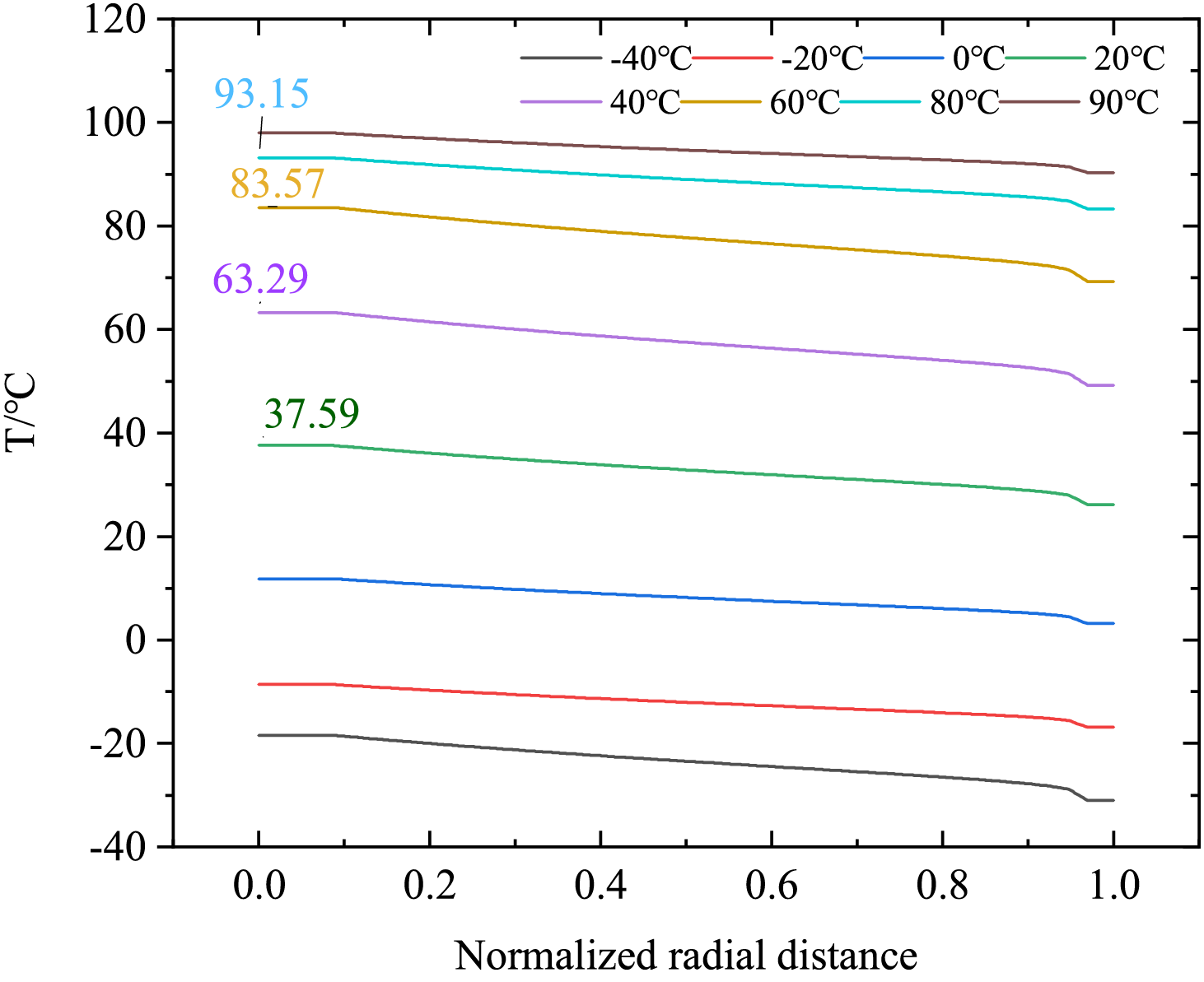
Figure 6: Radial temperature distribution of capacitor core during environmental temperature changes
3.1.2 Axial Temperature Distribution
The overall temperature distribution inside the bushing is graphically represented in the Fig. 7. Regardless of how the ambient temperature changes, the maximum temperature inside the bushing are always located in the middle and lower part. Fig. 8 illustrates the axial temperature distribution along the conductive rod. Notably, when ambient temperatures remain below 0°C, the maximum axial temperature is localized at the base of the rod. However, as ambient temperatures surpasses 0°C, the hottset point undergoes an upward shift, concentrating near the oil-immersed lower section of the rod.
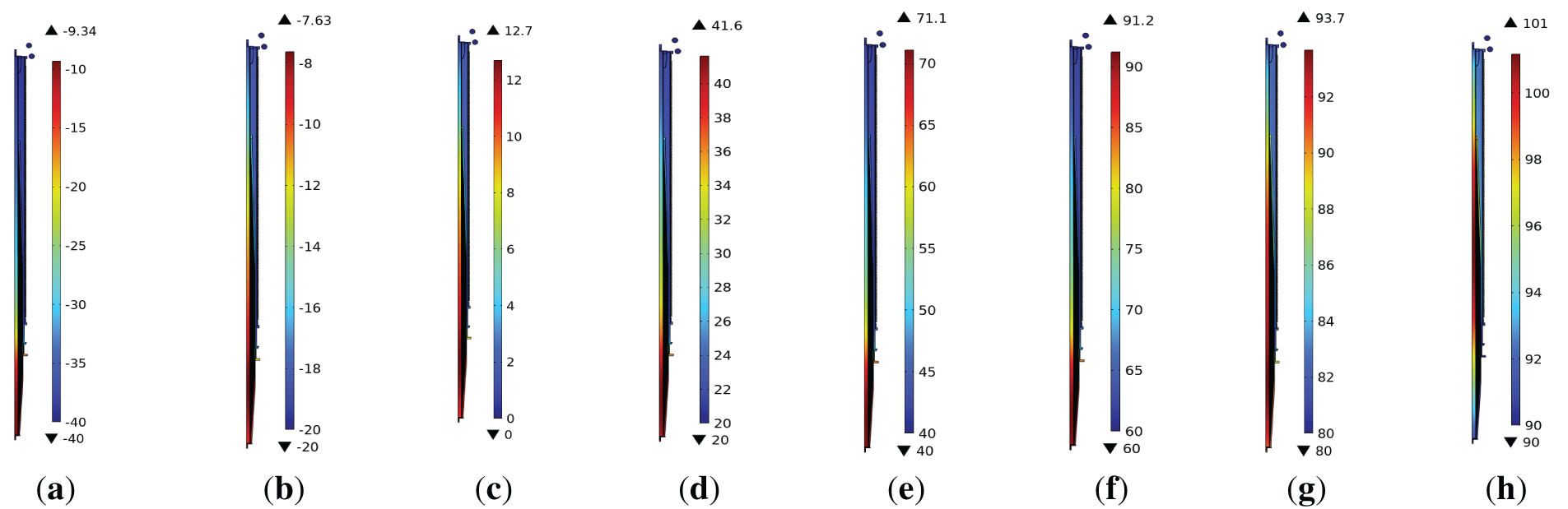
Figure 7: Cloud map of overall temperature distribution of bushing during environmental. (a) −40°C; (b) −20°C; (c) 0°C; (d) 20°C; (e) 40°C; (f) 60°C; (g) 80°C; (h) 90°C
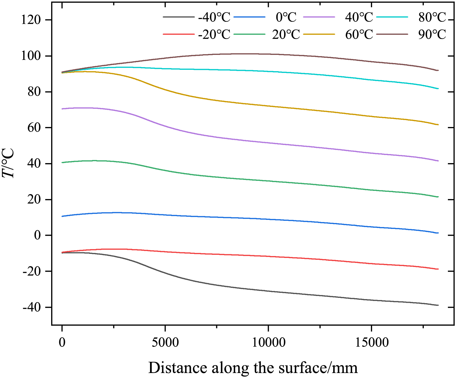
Figure 8: Axial temperature distribution of conductive rob during environmental temperature changes
The specific reasons are as follows: the total heat generated by the conductive rod remains constant. The heat at the upper end is conducted to the external environment through the SF6 insulating gas and the insulating sheath, while the heat at the lower end is dissipated through the insulating oil. Due to the relatively high temperature of the oil tank and the low thermal conductivity of the epoxy-impregnated paper composite insulation material, the heat dissipation conditions at the bottom of the bushing are poor. As a result, heat mainly accumulates in the middle and lower parts of the bushing, specifically the area below the flange. When the external ambient temperature is low, the temperature gradient between the inside and outside of the bushing near the flange is significant, the heat dissipated outward near the flange is significantly greater than the heat dissipated through the oil domain. Consequently, the hottest spot is located at the bottom of the conductive rod. This behavior can be attributed to the primary heat dissipation mechanisms at play. However, as the external ambient temperature rises, the temperature gradient near the flange decreases, reducing the heat dissipation capacity. Additionally, the convective heat transfer coefficient of the core surface in the gas domain (10 W/(m·K) is lower than that in the oil domain (80 W/(m·K)). Therefore, the heat exchange in the oil domain is greater than that in the gas domain. As a result, the position of the hottest spot gradually shifts upward, and this upward movement becomes more pronounced as the external ambient temperature continues to increase.
3.1.3 The Influence of Temperature Difference between Oil and Ambient on the Hot Spot Temperature
The relationship between the temperature difference and the hot-spot temperature value is shown in Fig. 9. Under the same temperature difference, there is a significant variation in the temperature value of the hottest spot inside the bushing, the temperature value of the hottest spot increases as the external ambient temperature rises. Therefore, the ambient temperature has a substantial impact on the temperature value of the hottest spot. Additionally, the temperature difference between the oil and the environment is also an important influencing factor, as illustrated in Fig. 10. When there is a temperature difference between the oil and the environment, it will affect the position of the hot spot. Although the position of the hot spot rises as the temperature increases, the degree of upward movement of the hot spot is relatively small when a temperature difference exists. When the external ambient temperature is 80°C, with a temperature difference of 10°C between the oil temperature and the external ambient temperature, the position of the hottest spot rises by 2457 mm. However, when the external ambient temperature is 90°C and the temperature difference is 0, the position of the hot spot rises rapidly to 11,356 mm.

Figure 9: The influence of ambient temperature on hot spot temperature under the same temperature difference
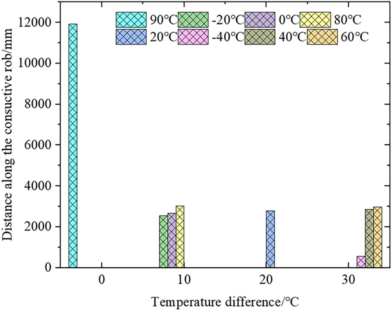
Figure 10: The influence of ambient temperature on hot spot displacement under the same temperature difference
This is because when there is a temperature difference between the oil temperature and the external ambient temperature, and the external environment is cooler than the oil temperature, heat dissipation in the oil is difficult, and more heat is dissipated through the flange. As a result, the position of the hot spot is lower. When both the ambient temperature and the oil temperature are 90°C, since the convective heat transfer coefficient of the oil tank is greater than that of the gas side, more heat is dissipated through the oil tank, causing the position of the hot spot to shift upward rapidly.
3.1.4 The Temperature Rise of the under Rated and 1.35 Times Overload Conditions
Figs. 11 and 12 depict the hot-spot temperature and corresponding temperature rise of the bushing under both rated and 1.35 times overload conditions. In both loading scenarios, the hot-spot temperature shows a consistent, monotonic increases as the ambient temperature rises. However, the temperature rise relative to the ambient temperature displays notable nonlinear behavior. During rated operation, the smallest temperature increase, which is 9°C, is observed when the ambient temperature is 90°C. While, the largest rise of 31°C occurs at an ambient temperature of 40°C. Under the condition of 1.35 times overload, the temperature increase varies from 16°C (when the ambient temperature is −20°C) to 34°C (when the ambient temperature is 60°C). This variation clearly indicates the heightened thermal stresses experienced by the bushing when subjected to the combined effects of high current and elevated temperature.

Figure 11: The change in hot-spot temperature of the bushing when the ambient temperature changes

Figure 12: The temperature rise of the hot-spot in the bushing when the ambient temperature changes
3.1.5 Discussion on Engineering Implication
In terms of thermal management, since the hot spot temperature inside the bushing always exists in the middle and lower part of the bushing’s conductive rod, it poses a great challenge to the heat dissipation treatment. The author’s team has also verified the improvement effect of the heat pipe on the temperature distribution inside the bushing through simulation in the early stage. The simulation results show that the heat pipe can reduce the temperature of the radial hot spot of the capacitor core by 41.06% [21]. By arranging temperature monitoring at the lower part of the conductive rod and combining with the heat pipe technology, the flow path and flow rate of the cooling working fluid are adjusted according to the hot spot temperature value and temperature distribution to make the cooling effect more uniform and avoid local overheating. However, whether this technology is effective still needs further verification.
In terms of material selection and thermal stress consideration, due to the potential adverse effects of frequent changes in thermal stress on the bushing. Therefore, during the manufacturing process of the bushing core, the internal aluminum foil screen and rolled paper should be strictly controlled to avoid internal defects. This can reduce the thermal stress caused by temperature changes, lower the risk of cracks in the bushing, and further prevent the occurrence of partial discharge and other risks.
In terms of measures for extreme working conditions, corresponding emergency plans need to be formulated for the extreme environmental temperatures in the Xinjiang region. For example, when the temperature is too high, measures such as temporarily adding cooling equipment and reducing the operating load of the equipment can be taken to ensure the safe and stable operation of the equipment, and avoid discharge accidents caused by excessive heat and thermal stress.
3.2 The Influence of Ambient Temperature on the Electric Field Distribution of Capacitor Core
Under rated operating conditions, the radial electric field strength within the bushing’s capacitive core exhibits minimal variation with ambient temperature fluctuations, as shown in Fig. 13 and 14. This stems from the fundamental nature of electric field distribution under alternating voltage, which is primarily determined by the material’s dielectric constant. Since the weak temperature dependence of the dielectric constant on temperature within the examined range, thermal fluctuations have a negligible impact on the electric field uniformity throughout the core.
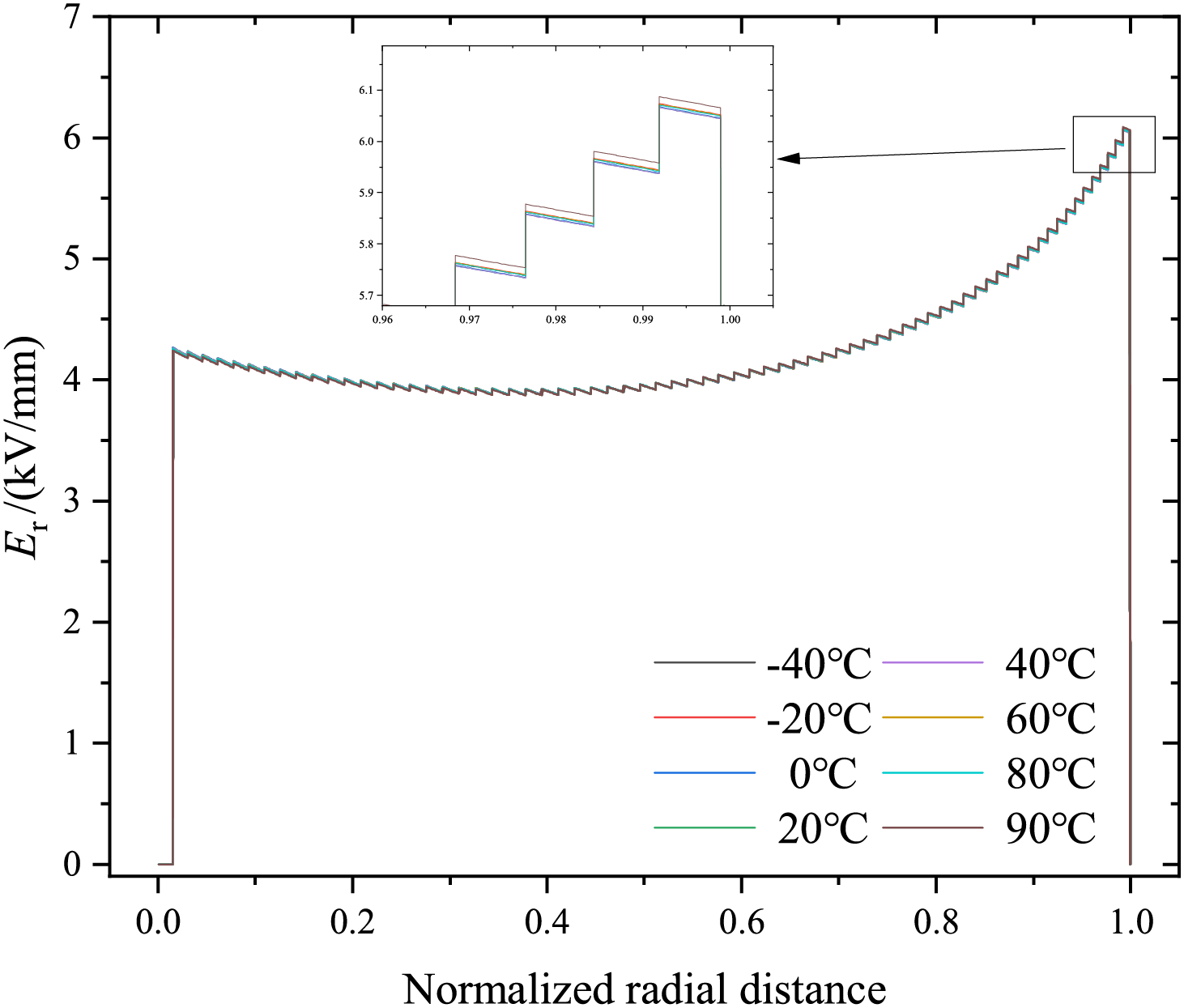
Figure 13: Radial electric field distribution line diagram of capacitor core during ambient temperature changes
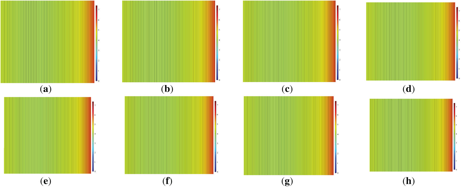
Figure 14: Radial electric field distribution cloud map of capacitor core during ambient temperature changes. (a) −40°C; (b) −20°C; (c) 0°C; (d) 20°C; (e) 40°C; (f) 60°C; (g) 80°C; (h) 90°C
This article establishes a multi-physics coupling model that integrates electrical, thermal, and fluid dynamics to evaluate the performance of ERIP bushings in750 kV high-voltage reactors. The model analyzes thermal field distributions within the bushing and radial electric field profiles of the capacitor core under ambient temperature fluctuations ranging from −40°C to 90°C and oil temperature variations spanning −10°C to 90°C. The key findings are summarized as follows:
(1) Radial thermal gradient: Irrespective of external temperature changes, the radial temperature distribution of the capacitor core decrease monotonicaly from the conductive rod outward. The highest temperature consistently occur in the vicinity of the rod.
(2) Axial hot-spot migration: The hottest point shifts upward with the ambient temperature rising. When there is a temperature difference between the oil and external environment, the upward displacement of the hot spot position remains relatively limited. Conversely, in the absence of such a temperature difference, the hot spot position experiences a rapid upward shift, with a maximum increase of 11,356 mm.
(3) Nonlinear temperature rise: The internal temperature rise relative to ambient temperature exhibits nonlinear behavior. During rated operation, the minimum temperature rise (9°C) is observed at an ambient temperature of 90°C, while the maximum rise (31°C) occurs at 40°C ambient. Under 1.35 times overload, the temperature rises range from 16°C (−20°C ambient) to 34°C (0°C ambient), increasing the thermal stresses.
(4) Electric field stability: The radial electric field distribution within the capacitor core remains stable across varying external temperature. This stability is attributed to the fact that the dielectric constant, which governs the electric field, shows minimal dependence on temperature.
Acknowledgement: This work was supported by the Reliability Improvement Technology and Application Epoxy Impregnated Paper Bushing in Extreme Environment.
Funding Statement: This work was supported by the Reliability Improvement Technology and Application of Epoxy Impregnated Paper Bushing in Extreme Environments under granted DQ30DK24001P.
Author Contributions: Minjie Li: writing—original draft preparation, Wanhao Shi: data curation, Dingqian Yang: writing—format proofreading, Manman Yuan: writing—review and editing, Jiabao Du: drawing the article pictures, Xuandong Liu: verifying the accuracy of the article. All authors reviewed the results and approved the final version of the manuscript.
Availability of Data and Materials: The data that support the findings of this study are available from the Corresponding Author, Dingqian Yang, upon reasonable request.
Ethics Approval: Not applicable.
Conflicts of Interest: The authors declare no conflicts of interest to report regarding the present study.
References
1. Sun LP, Ma J, Song ZH, Zhang JM. Current situation and development suggestions of ultra-high voltage transmission channels in China under thegoal of Dual Carbon. Coal Econ Res. 2024;44(9):124–30. (In Chinese). doi:10.13202/j.cnki.cer.2024.09.007. [Google Scholar] [CrossRef]
2. Alassi A, Banales S, Ellabban O, Adma G, Maciver C. HVDC transmission technology review, market trends and future outlook. Renew Sustain Energy Rev. 2019;112:530–54. doi:10.1016/j.rser.2019.04.062. [Google Scholar] [CrossRef]
3. Xie XJ, Luo XQ, Hu W, Ye Q, Xu Z, Huang Y. DC voltage flashover characteristics of SF6 insulated DC wall bushing under uneven rain conditions. High Volt Eng. 2021;47(6):2084–90. (In Chinese). doi:10.13336/j.1003-6520.hve.20200418. [Google Scholar] [CrossRef]
4. Wang QY, Liao JT, Tian HD, Liu P, Peng ZR. Regularity analysis of the temperature distribution of epoxy impregnated paper converter transformer bushings. IEEE Trans Dielectr Electr Electr Insul. 2017;24950:3254–64. doi:10.1109/TDEI.2017.006685. [Google Scholar] [CrossRef]
5. Ganguli S, Roy AK, Anderson DP. Improved thermal conductivity for chemically functionalized exfoliated graphite/epoxy composites. Carbon. 2008;46(5):806–17. doi:10.1016/j.carbon.2008.02.008. [Google Scholar] [CrossRef]
6. Xie GS, Shi SF, Wang QL, Wang QY, Liu P, Peng ZR. Simulation and experimental analysis of ±800 kV converter transformer valve-side bushing under high current. High Volt Eng. 2024;50(3):994–1002. (In Chinese). doi:10.13336/j.1003-6520.hve.2022128510.1049/gtd2.12491. [Google Scholar] [CrossRef]
7. Zhao XY, Chen QG, Yang HD, Chi MH. Optimal design of insulation structure in DC bushing under temperature gradient. High Volt Eng. 2022;48(3):928–37. (In Chinese). doi:10.13336/j.1003-6520.hve.20210864. [Google Scholar] [CrossRef]
8. Wang FZ, Drzal LT, Qin Y, Huang ZX. Mechanical properties and thermal conductivity of graphene nanoplatelet/epoxy composites. J Mater Sci. 2015;50(3):1082–93. doi:10.1007/s10853-014-8665-6. [Google Scholar] [CrossRef]
9. Zhang H, Wan BQ, Xu ZM, Hu W, Liu TW, Luo XQ. Temperature sensitivity of insulation characteristics of epoxy resin impregnated paper bushing. Insul Surge Arresters. 2021;2:72–7. (In Chinese). doi:10.16188/j.isa.1003-8337.2021.02.011. [Google Scholar] [CrossRef]
10. Xu ZM, Hu W, Yin PB, Wang J, Xie XJ, Peng ZR. Temperature distribution and insulation characteristics of epoxy resin impregnated paper bushing under current carrying condition. High Volt Eng. 2023;49(7):2909–18. (In Chinese). doi:10.13336/j.1003-6520.hve.20221088. [Google Scholar] [CrossRef]
11. Jyothi NS, Ramu TS, Mandlik M. Temperature distribution in resin impregnated paper insulation for transformer bushings. IEEE Trans Dielectr Electr Insul. 2010;17(3):931–8. doi:10.1109/TDEI.2010.5492269. [Google Scholar] [CrossRef]
12. Zhang S, Peng Z, Liu P, Hu W, Wang H. Electro-thermal coupling model for computation of radial temperature and electric field of resin impregnated paper high voltage direct current bushing. Proc CSEE. 2013;33(22):191–200. (In Chinese). doi:10.13334/j.0258-8013.pcsee.2013.22.026. [Google Scholar] [CrossRef]
13. Zhang S, Peng Z, Liu P, Li B, Hu W, Cheng H. Experimental study on electro-thermal coupling model applied in computation of radial temperature distribution of RIP oil-gas bushing condenser. Power Syst Technol. 2012;36(12):289–96. (In Chinese) doi:10.13335/j.1000-3673.pst.2012.12.018. [Google Scholar] [CrossRef]
14. Zhang S, Peng Z, Liu P. Inner insulation structure optimization of UHV rip oil-SFs bushing using electro-thermal simulation and advanced equal margin design method. IEEE Trans Dielectr Electr Insul. 2014;21(4):1768–77. doi:10.1109/TDEI.2014.004211. [Google Scholar] [CrossRef]
15. Wang Q, Yang X, Peng Z, Liu P. 3D coupled electromagnetic-thermal-fluid method for computation of temperature field of converter transformer RIP bushings. Proc CSEE. 2016;36(22):6269–75. (In Chinese). doi:10.13334/j.0258-8013.pcsee.152365. [Google Scholar] [CrossRef]
16. Si WR, Fu CZ, Su L, He L, Wen H, Jiang Y, et al. Research on electric field distribution characteristics simulation under typical defects in the scaled model of valve side bushing of UHV converter transformer. High Volt Appar. 2024;60(12):85–94. (In Chinese). doi:10.13296/j.1001-1609.hva.2024.12.010. [Google Scholar] [CrossRef]
17. Tang H, Li J, Zhang H, Zhang S, Wu G, Jia P. Axial and radial temperature distribution of the valve side bushing in UHVDC converter transformer under high ambient temperature and large current. Proc CSEE. 2017;37(18):5494–503. (In Chinese). doi:10.13334/j.0258-8013.pcsee.161766. [Google Scholar] [CrossRef]
18. He Y, Zhang S, Yang F, Lu Z. Research on model of electro-thermal coupling in valve side bushing considering nonlinear characteristics of capacitor core insulation medium. Power Syst Technol. 2025;49(4):1689–97. (In Chinese). doi:10.13335/j.1000-3673.pst.2024.0363. [Google Scholar] [CrossRef]
19. Shi SF, Liu S, Xie GS, Wang QL, Wang QY, Liu P, et al. Design and optimization analysis od water cooling heat dissipation for the valve-side bushing of converter transformer. Proc CSEE. 2023;43(12):4861–71. (In Chinese). doi:10.13334/j.0258-8013.pcsee.213311. [Google Scholar] [CrossRef]
20. Zhang SL, Peng ZR, Cheng JW, He YS. Research on digital twin model of outgoing-line device area of UHV converter transformer based on three-dimensional configuration and electro-thermal sensing. High Volt Appar. 2022;58(7):128–40. (In Chinese). doi:10.13296/j.1001-1609.hva.2022.07.016. [Google Scholar] [CrossRef]
21. Li M, Liu X, Shang G. Optimization of electric thremal flow field in valve-side bushing of converter transformer based on capillary wick heat pipe. Electr Mach Control. 2024;28(9):1–10. (In Chinese). doi:10.15938/j.emc.2024.09.001. [Google Scholar] [CrossRef]
Cite This Article
 Copyright © 2025 The Author(s). Published by Tech Science Press.
This work is licensed under a Creative Commons Attribution 4.0 International License , which permits unrestricted use, distribution, and reproduction in any medium, provided the original work is properly cited.
 Downloads
 Citation Tools