
 Submit a Paper
 Propose a Special lssue
 Open Access
ARTICLE

Load Balancing Control Strategy for Multi-Substation Flexible Interconnection Distribution Networks Considering Unbalanced Power Compensation
1 Electric Power Research Institute of Guizhou Power Grid Co., Ltd., Guiyang, 550002, China
2 XJ Electric Corporation, Xuchang, 461000, China
* Corresponding Author: Jikai Li. Email:
(This article belongs to the Special Issue: Emerging Technologies for Future Smart Grids)
Energy Engineering 2025, 122(10), 4061-4080. https://doi.org/10.32604/ee.2025.067304
Received 29 April 2025; Accepted 04 July 2025; Issue published 30 September 2025
 View Full Text
 Download PDF
Abstract
Aiming at the challenge of complex load balancing coordination for a three-phase four-leg (3P4L) based multi-ended low voltage flexible DC distribution system (M-LVDC) considering unbalanced power compensation, this paper proposes a phase-split power decoupling unbalanced compensation strategy based load balancing strategy for 3P4L based M-LVDC. Firstly, the topology and operation principle of the 3P4L-based M-LVDC system is introduced, and quasi-proportional resonant (QPR) based phase-split power current control for the 3P4L converter is proposed. Secondly, a load-balancing control strategy considering unbalanced compensation for 3P4L-based M-LVDC is presented, in which the control diagrams for each 3P4L-based converter are detailed. The core idea of the proposed strategy is to comprehensively consider the imbalance compensation and load rate balancing between the two areas to calculate the split-phase power and current reference values of each 3P4L converter and achieve the static error-free tracking of the reference values through the QPR current inner-loop control. These reference values are then tracked with zero steady-state error using QPR current inner-loop control. Finally, the effectiveness of the proposed control strategy is verified through a 3P4L M-LVDC case study conducted on the PSCAD/EMTDC software. The results indicate that the proposed method not only can reduce the three-phase imbalance degrees from >20% to <0.5%, but also achieve excellent balanced load rates, with the load-rate difference smaller than 1.5%.Keywords
In recent years, the integration of photovoltaic (PV) systems into distribution networks has emerged as a pivotal strategy in the global transition towards sustainable energy. According to the International Energy Agency (IEA) 2024 report, the cumulative installed capacity of distributed PV systems worldwide has reached over 1200 GW, with an annual growth rate of approximately 25% in the past five years [1]. However, the PV generation is highly dependent on weather conditions and hence not uniform. This lack of uniformity of the solar generators makes the grid system highly vulnerable [2]. Meanwhile, with the grid connection of large-scale distributed photovoltaics and the widespread access of electric vehicles (EVs) and other energy substitution loads to the distribution network, the large-scale, disorderly access directly leads to prominent power quality issues, such as three-phase imbalance and low voltage. It also causes problems like insufficient capacity and uneven loading of distribution transformer areas (DTAs) and power supply lines [3–6]. Currently, for the interconnection and mutual power supply between Distribution Transformers (DTAs), most methods are based on topological reconfiguration and state switching of switch combinations [7,8]. However, in the process of interconnection and mutual power supply through this traditional AC (Alternating Current) method, due to the characteristic of “closed-loop design and open-loop operation” of the AC power grid, the bus tie switches between DTAs are often in a cold standby state during the normal operation of the system. Their controllability of mutual power support and load balancing capability are not sufficient to support the rapidly growing demand at both the source and load ends in the current DTA [9]. Moreover, the disordered connection of new types of sources or loads, such as PV and electric vehicles (EVs) in low-voltage distribution areas, has led to severe three-phase unbalance issues [10].
Flexibly interconnecting multiple low-voltage distribution areas through AC-DC converters can significantly enhance the power supply capacity of the distribution areas and achieve the governance of power quality in low-voltage distribution areas [11]. However, commonly-used three-phase three-leg (3P3L) interconnection converters have relatively poor capability to handle asymmetric and non-linear loads, and cannot achieve the governance of three-phase unbalance. In contrast, the three-phase four-leg converter (3P4L), which includes a separately controllable fourth leg, adds a flow path for the zero-sequence leg and can realize the independent control of the phase-separated power of each phase, making it an effective means to solve the problem of three-phase unbalance governance in low-voltage distribution areas [12–15]. However, its large-scale application still faces some problems. On the one hand, the control of existing three-phase four-leg converters is mainly based on the decoupling of positive, negative, and zero sequences, and the methods used are mostly the symmetrical component method [16], the 1/4 cycle delay method [17], the positive and negative sequence separation method based on the second order generalized integrator [18,19], etc. Due to the presence of all-pass filters, it is easy to cause distortion of the separated positive and negative sequence voltage components, resulting in a large overall calculation amount and a complex implementation process. On the other hand, most of the existing load balancing strategies for flexible interconnected distribution areas are based on symmetrical load with 3P4L-based M-LVDC conditions [20,21], without considering the characteristics under unbalanced loads. When the load rates of multiple distribution areas are inconsistent, there is no research on the multi-VSC coordinated control that takes into account multiple objectives, such as three-phase unbalance compensation and load balancing rate.
To address this, this paper proposes a phase-split power decoupling unbalanced compensation strategy based load balancing strategy for 3P4L-based M-LVDC. The main contribution of this paper can be summarized as follows:
(1) The power decoupling control mechanism of the 3P4L converter is clarified based on the switching cycle average method, then a direct current control strategy using quasi-proportional resonant (QPR) control is proposed, which can achieve zero-error tracking of each phase AC current.
(2) Based on the power analysis, the calculation principles for the reference value of each phase current under the three-phase unbalance compensation mode are clarified, and then a load balancing strategy for 3P4L-based M-LVDC is proposed.
Through a PSCAD/EMTDC software simulation model of 3P4L-based M-LVDC, the effectiveness of the proposed method has been verified.
The paper is organized as follows: Section 2 of this paper introduces the topology of 3P4L-based M-LVDC, and the power decoupling control mechanism and QPR current control of the 3P4L converter are clarified. Section 3 introduces the proposed load balancing strategy, which is based on a phase-split power decoupling unbalanced compensation strategy. Section 4 introduces simulation analysis and verification. And Section 5 is the conclusion of this paper.
2 Topology and Operation Principle of the 3P4L-Based M-LVDC System
2.1 Topology of 3P4L-Based M-LVDC
Fig. 1 shows the typical topology of a 3P4L-based M-LVDC system, which consists of two distribution areas and an M-LVDC network composed of three voltage source converters (VSCs). Specifically, VSC1 is located at the transformer outlet of Distribution Area I, VSC2 at the end of the distribution line in Area I, and VSC3 at the transformer outlet of Distribution Area II. These VSCs are connected via low-voltage DC lines erected on the same pole, thereby establishing energy flow paths for both intra-area (VSC1-VSC2) and inter-area (VSC1-VSC3) source-load interactions.
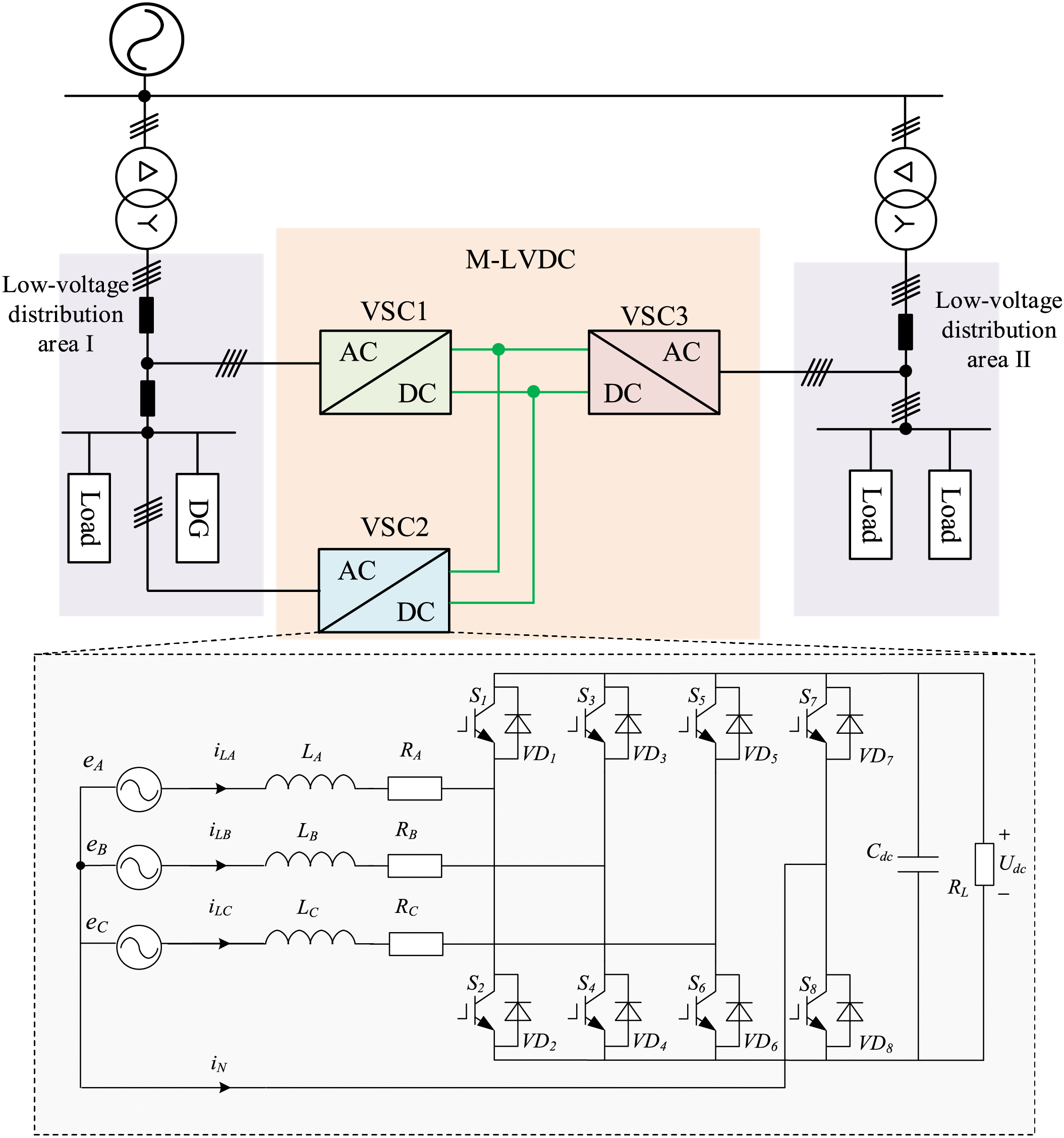
Figure 1: Typical topology of 3P4L-based M-LVDC systems
The principles of unbalanced compensation and load balancing in the M-LVDC system are as follows: Before M-LVDC integration, the asymmetric connection of loads in distribution areas leads to imbalanced three-phase loads, manifested as unbalanced three-phase currents in the distribution transformer. By embedding the M-LVDC system and interconnecting the head and tail ends of Distribution Area I via VSC1 and VSC2, where VSC1 stabilizes the DC voltage and VSC2 performs phase-split power compensation at the tail end, the three-phase power delivered by the distribution transformer is balanced, thereby achieving balanced three-phase currents at the head end of Distribution Area I. After comprehensively considering the load characteristics of both distribution areas, VSC3 designs appropriate phase-split power control commands to balance the load rates between Distribution Area I and Distribution Area II.
The key to achieving three-phase unbalance compensation lies in realizing phase-split power decoupling control. Traditional three-phase three-leg (3P3L) VSCs exhibit strong coupling among the three-phase powers, making it challenging to achieve phase-split power decoupling control. Therefore, the VSCs in this system adopt the three-phase four-leg (3P4L) converter topology shown in Fig. 1. Compared with the 3P3L converter, the 3P4L converter adds an additional leg connected to the neutral point N, which enhances the control flexibility of the converter, provides a path for unbalanced currents, and enables compensation for three-phase unbalanced power.
2.2 Mathematical Model of Three-Phase Four-Bridge-Arm Converter
Fig. 1 shows the circuit topology of the 3P4L VSC converter, where eA, eB, and eC are the three-phase power sources, iLA, iLB, and iLC are the three-phase currents, iLN is the neutral-line current, RA, RB, RC are the resistances of the three-phase circuits, LA, LB, LC are the three-phase filter inductors, Cdc is the DC-side support capacitor, and Udc is the DC-side voltage. Each leg of the 3P4L converter has two switching devices, defining the switching functions qA, qB, qC, qN to represent the switching state for the four legs. When qi = 1 (i = A, B, C, N), it indicates that the upper device is ON and the lower device is OFF, and vice versa.
Defining qAN = qA − qN, qBN = qB − qN, qCN = qC − qN. The relationship between the AC voltage of the legs and the DC-side voltage can be obtained as:
Based on Kirchhoff’s Voltage Law (KVL), the state equations of the 3P4L converter can be expressed as:
By combining Eqs. (2) and (3) and then simplifying, the following expression can be obtained:
Defining vectors iL, e, and s are as follows:
Based on the average method of the switching period, the system equations can be obtained:
Defining
where di (i = A, B, C, N) is the duty cycle of the i-th leg, which can be expressed as:
Since the inductor current vector iL is a continuous function of time in a switching cycle, which can be regarded as the same value, Eq. (9) can be simplified as:
Therefore, the switching period average model of 3P4L converter is obtained by synthesizing Eqs. (5)–(10).
The equivalent circuit diagram of the switching period average model of the 3P4L converter obtained from Eq. (11) is shown in Fig. 2. It can be seen that the phase of the 3P4L converter is independent, and the circuit parameters of each leg are only related to the control quantity of the bridge arm, and there are no coupling effects; an independent phase-split power control strategy can be realized.
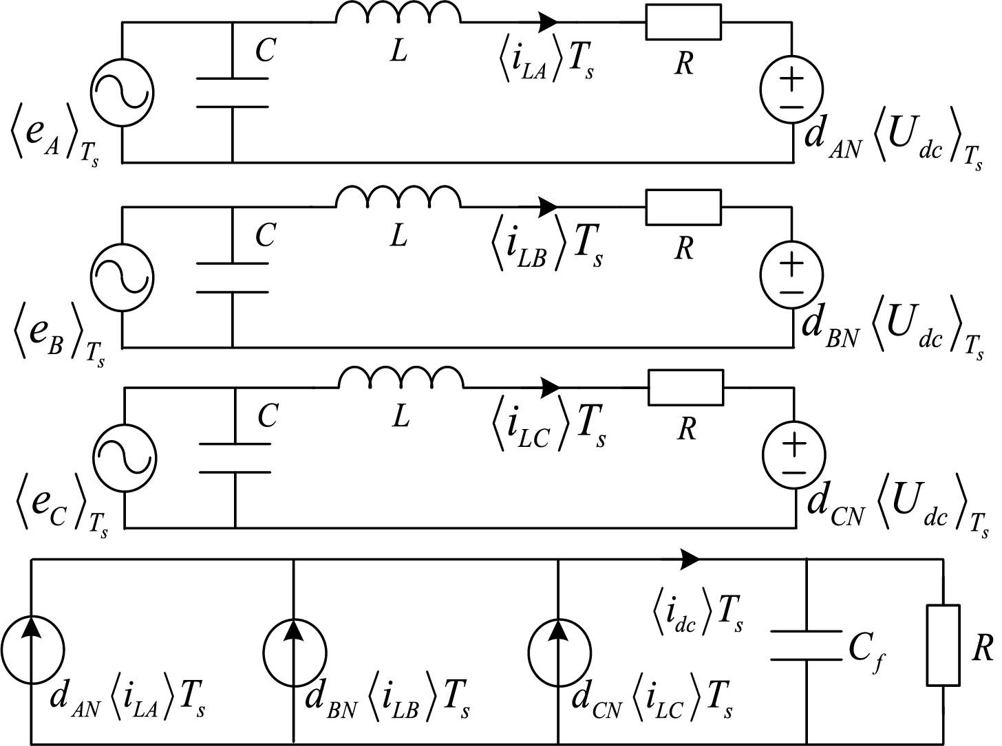
Figure 2: Equivalent circuit of the switching cycle averaging model for the 3P4L converter
2.3 Quasi-PR-Based Phase-Split Power Control Strategy
The key point of the three-phase imbalance compensation in the distribution area is using the 3P4L converter to achieve the independent phase-split power control, i.e., independently controlling the power of each phase according to the load conditions. Based on the equivalent averaging model for the 3P4L converter, a quasi-PR-based phase-split current control strategy is proposed, which achieves zero-error tracking of the output current reference value by a quasi-PR current inner-loop and eliminates the need for sequence decoupling and outer-loop control.
The control function of the QPR current loop can be expressed as:
where ILiref (i = A, B, C, N) is the reference value of the current loop, Li (i = A, B, C, N) are the inductors for each phase.
The reference current value of the fourth leg ILNref can be calculated as:
And the general transfer function of a QPR controller can be obtained as follows:
where Kp is the proportional coefficient of the controller, Kr is the resonant frequency coefficient, ωc is the cutoff frequency of the controller, ω0 is the resonant frequency of the controller, which is generally set to the grid frequency ω0 = 100π (rad/s). Based on Eq. (14), the closed-loop structure control block diagram can be drawn as Fig. 3. The performance of the QPR controller is mainly affected by Kp, Kr, and ωc, which can be selected as Kp = 200, Kr = 150, and ωc = 10 by comparing the performance difference under different parameters.
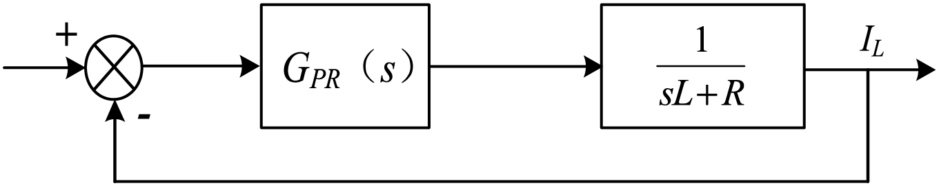
Figure 3: The quasi-PR-based current closed-loop mode controller
3 Load Balancing Control Strategy Considering Unbalanced Compensation for 3P4L-Based MLVDC
3.1 Overall Control Block Diagram
Fig. 4 illustrates the collaborative control block diagram of the load balancing control strategy considering unbalanced compensation for 3P4L-based M-LVDC. In which, VSC1 employs Udc control to stabilize the DC-side voltage, VSC2 adopts unbalanced power compensation control to provide power compensation for the unbalanced load in Area 1, VSC3 utilizes an unbalanced power transfer strategy to achieve load balancing between Area 1 and Area 2 (n1 = n1) and unbalanced compensation in Area II. The specific control description can be detailed as follows.
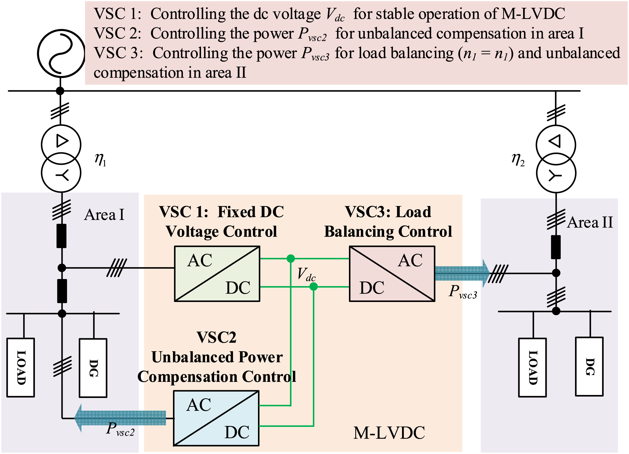
Figure 4: Diagram of load balancing control strategy considering unbalanced compensation for 3P4L-based M-LVDC
3.2 Fixed DC Voltage Control for VSC1
In M-LVDC systems, controlling the DC bus voltage is essential, which is a core link to ensure stable system operation, power quality, and equipment safety. Its importance is mainly reflected in maintaining system power balance and ensuring power quality and normal equipment operation. And VSC1 is connected to the beginning of Area 1, which is controlled to obtain a stable DC voltage. The control diagram of the VSC1 is shown in Fig. 5. In which, the outer loop of VSC1 adopts DC voltage control, providing reference values ILAref, ILBref, ILCref for the inner loop current control. The reference current of the N-phase bridge arm is equal to the sum of the three phases A, B, and C, but in the opposite direction. After obtaining the reference current value for each phase, the inner loop uses the aforementioned Quasi-PR direct current control to achieve zero-error tracking, and the switching signals are generated through PWM modulation.
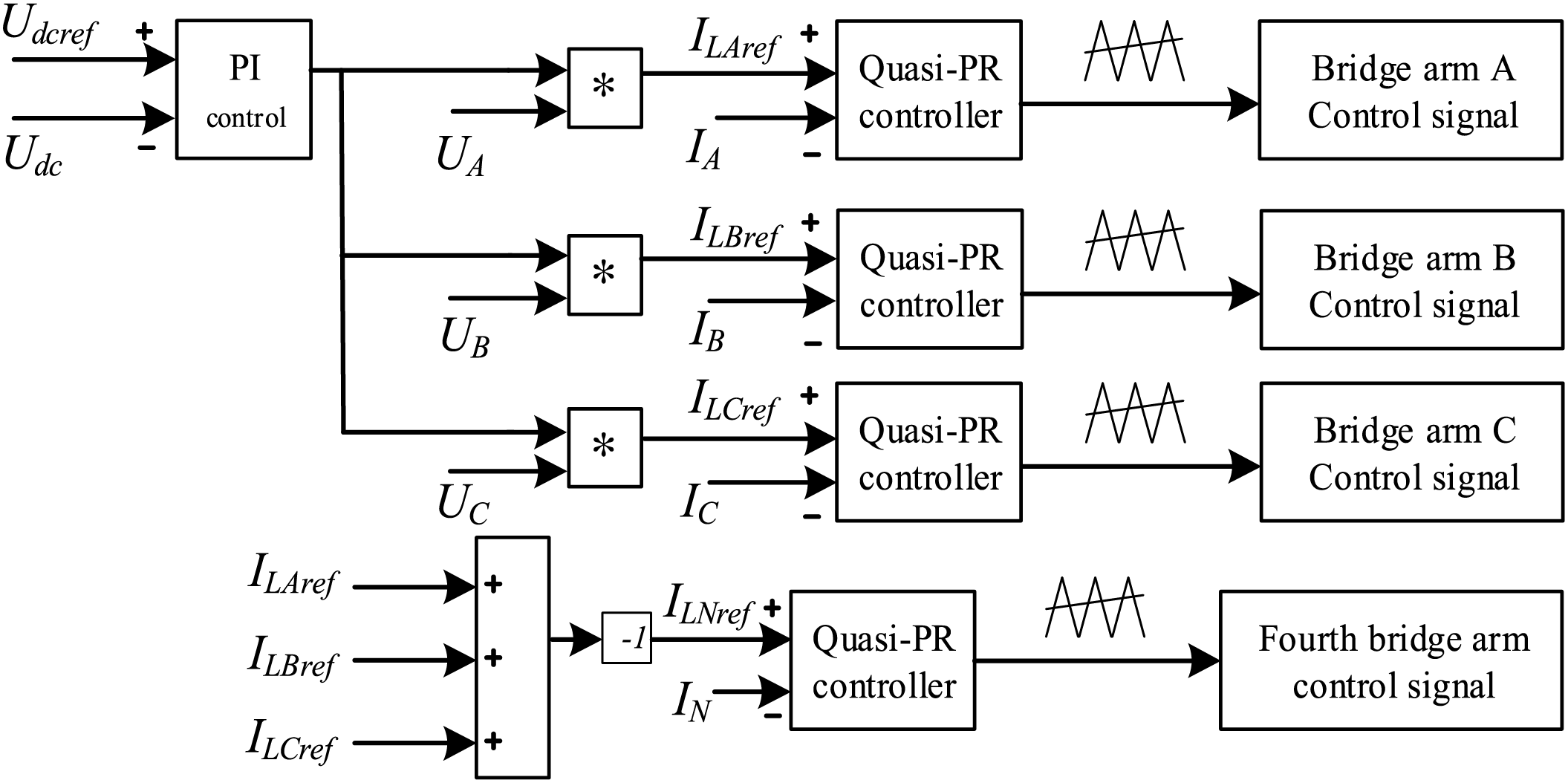
Figure 5: The control diagram of the fixed DC voltage control for VSC1
3.3 Unbalanced Power Compensation Control for VSC2
The VSC2 compensates power at the end of the distribution Area I by using the phase-split power control. It is necessary to first calculate the compensation power reference value, and then calculate the current reference value for quasi-PR current direct control.
3.3.1 Phase-Split Power Reference Value Calculation for Unbalanced Power Compensation
Firstly, the three-phase output power PTx (x = A, B, C) of the distribution area1 is calculated as:
where VTxrms (x = A, B, C) represents the RMS values of the three-phase output voltages of the transformer, and ITxrms (x = A, B, C) represents the RMS values of the three-phase output currents of the transformer. θVTx (x = A, B, C) represents the phase angles of the three-phase voltages, and θITx (x = A, B, C) represents the phase angles of the three-phase currents. During the measurement process, the fundamental amplitude and phase of the AC side voltage and current need to be obtained through a Fourier transform to avoid the impact of harmonics.
Subsequently, the three-phase power Px (x = A, B, C) at the current balance point is calculated as:
where Vxrms (x = A, B, C) represents the RMS values of the three-phase voltages at that point, and Ixrms (x = A, B, C) represent the RMS values of the three-phase currents at that point. θVx (x = A, B, C) represents the phase angles of the three-phase voltages at that point, and θIx (x = A, B, C) represents the phase angles of the three-phase currents at that point. Similarly, when calculating and measuring, the fundamental amplitude and phase of the AC side voltage and current need to be obtained through a Fourier transform to avoid the impact of harmonics.
Finally, the phase-split power reference value Pxref (x = A, B, C) for VSC2 can be calculated as:
where
3.3.2 Current Reference Value Calculation for Unbalanced Power Compensation
When calculating the input current reference value, the power transmission direction needs to be considered; hence, a single-input comparator F is introduced. When the reference power in Eq. (17) is positive, the output of the single-input comparator is 1, indicating that the power flows from the DC side to the AC side via VSC2. When the reference power is set to a negative value, the output of the single-input comparator is −1, indicating that the power flows from the AC side to the DC side via VSC2.
The peak values of the three-phase reference current IVSC2xpeak (x = A, B, C) can be calculated by the reference power as:
where Qxref (x = A, B, C) represents the reference reactive power, and VVSC2xrms (x = A, B, C) represents the RMS values of the three-phase AC voltages on the AC side of VSC2.
After obtaining the peak values of the three-phase current, the input current reference values Ixref (x = A, B, C) for the current loop can be expressed as:
Among them, Fx (x = A, B, C) represents the output signals of the three-phase single-input comparators, and θVSC2Ix (x = A, B, C) represents the phase angles of the three-phase current, which can be calculated as:
where θVx (x = A, B, C) represents the phase angles of the three-phase voltage. These are measured by inputting the voltages from the AC side of VSC2 into a phase-locked loop (PLL) after passing through a delay module. This approach avoids potential phase shift errors in voltage phase angle measurement caused by three-phase imbalance at the end of the distribution area.
Fig. 6 plots the block diagram of the unbalanced power compensation control for VSC2. In which, the outer loop of VSC2 adopts a power loop, which provides reference values ILAref, ILBref, ILCref by Eqs. (15)–(20). The reference current of the N-phase bridge arm is equal to the sum of the three phases A, B, and C, but in the opposite direction. After obtaining the reference current value for each phase, the inner loop uses the aforementioned Quasi-PR direct current control to achieve the zero-error tracking, and finally, the switching signals are generated through PWM modulation.
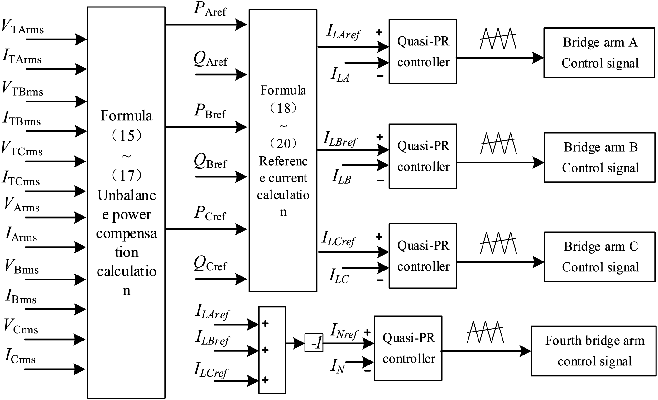
Figure 6: The control diagram of unbalanced power compensation control for VSC2
3.4 VSC3 Split-Phase Power Control Considering Load Balancing
The VSC3 draws power from the DC side and transfers it to Distribution Area II, achieving power supply transfer, alleviating the heavy load condition of the distribution transformer in Area II, and thus realizing load balancing between the two areas. The goal of the load balancing control strategy of VSC3 is to equalize the load rates of the two distribution areas. Therefore, it is necessary to first calculate the power supply transfer reference value and then calculate the current reference value for phase-by-phase quasi-PR current direct control.
Calculation of Unbalanced Power Supply Transfer Reference Value
Firstly, the total power ST1 transmitted by Area I can be calculated as:
Similarly, the total power ST2 transmitted by Area II can be calculated as:
where VT2xrms (x = A, B, C) are the RMS values of the three-phase voltages in Area II. IT2xrms (x = A, B, C) are the RMS values of the three-phase currents in Area 2II.
Assuming that after power transfer, the load rates of Area I and Area II are equal, then the following equation can be obtained.
where Stra represents the transferred power, and ST1N, ST2N are the rated power of the transformer in Area I and Area II. Simplifying Eq. (23) yields,
Then, the load rate n2 of Area 2 can be calculated as:
Subsequently, the output three-phase power ST2x (x = A, B, C) of the distribution transformer in Area 2 can be calculated as:
Finally, the three-phase active power reference values Pxref for VSC3 are calculated as:
where
The block diagram of the unbalanced power compensation control for VSC3 is shown in Fig. 7. In which, the power outer loop is used to calculate the reference value, and the input current reference value for VSC3 can be calculated as that of VSC2 with Eqs. (18)–(20). Then, the Quasi-PR direct current control is used to achieve the zero-error tracking. Finally, the switching signals are generated through PWM modulation.
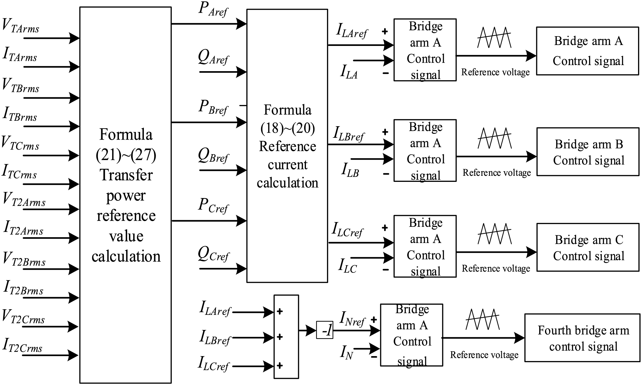
Figure 7: The control diagram of VSC3 split-phase power control considering load balancing
4 Simulation Analysis and Verification
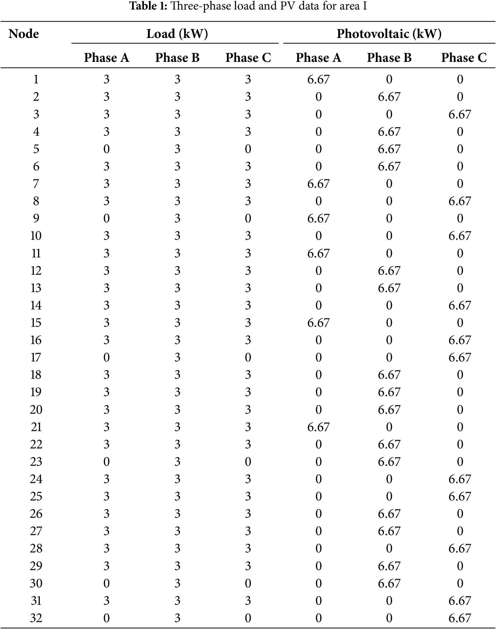
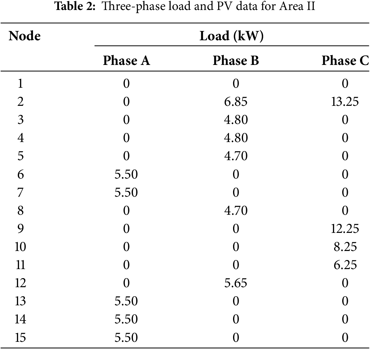
To verify the effectiveness of the proposed control strategy, a simulation model was built in the PSCAD/METDC simulation software based on the actual topology of a local distribution area. The typologies of Distribution Area I and Distribution Area II are shown in Fig. 8. The AC-side voltage of the converter is 380 V/50 Hz, and the filter inductance of the 3P4L converter is 250 mH. The switching frequency is 10 kHz. The transformer capacity of Distribution Area 1 is 200 kVA, and the loads at each node and the connected photovoltaic (PV) data are shown in Table 1. The PV system is connected to different nodes, and its capacity is 10 kW. Generally, the PV system consists of a PV panel, an MPPT DC-DC converter, and a grid-connected inverter to connect the AC system. But the control target is to coordinate the 3P4L VSCs control to achieve the load balancing and three-phase imbalance suppression. Therefore, the PV system is not detailed in the manuscript, which only seems like a power source. The transformer capacity of Distribution Area 2 is 100 kVA, and the loads at each node and the connected photovoltaic (PV) systems are shown in Table 2.
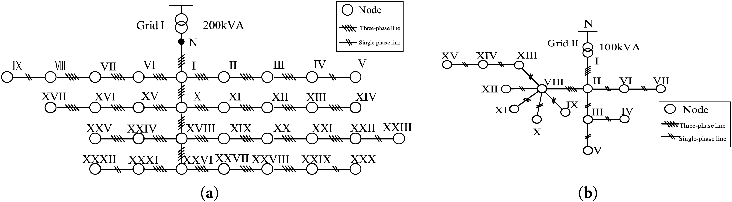
Figure 8: The topology of the distribution area in the case study. (a) Area I; (b) Area II
4.1 Load Condition and Voltages Analysis in Area I and Area II without M-LVDC
When the M-LVDC is not introduced to Distribution Area I, the load condition and voltage analysis in Area I are shown in the Fig. 9. It can be seen that the phase power in Node 1 is unbalanced, i.e., PT1A = 40.33 kW, PT1B = 55.15 kW, and PT1C = 38.91 kW. The three-phase voltage is basically balanced, hence the amplitude of Phase A current is the smallest, and that of Phase B current is the largest. The three-phase power unbalance degree λI at Node 1 is calculated to be 23.11%, and the load rate of area I n1 is 67.64%.
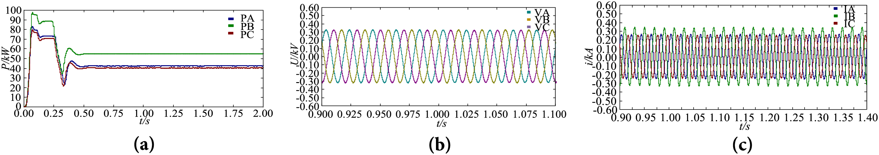
Figure 9: Load condition and voltages analysis in Area I. (a) Power curve of Node 1; (b) Voltage waveform of Node 1; (c) Current waveform of Node 1
When the M-LVDC is not introduced to Distribution Area II, the load condition and voltage analysis in Area II are shown in the Fig. 10. It can be seen that the phase power in Node 1 is unbalanced, i.e., PT2A = 27.41 kW, PT2B = 32.08 kW, and PT2C = 40.15 kW. The three-phase voltage is basically balanced. The three-phase power unbalance degree λI at 20.89%, the load rate of area II n2 is 99.27%, exhibiting heavy-load conditions.
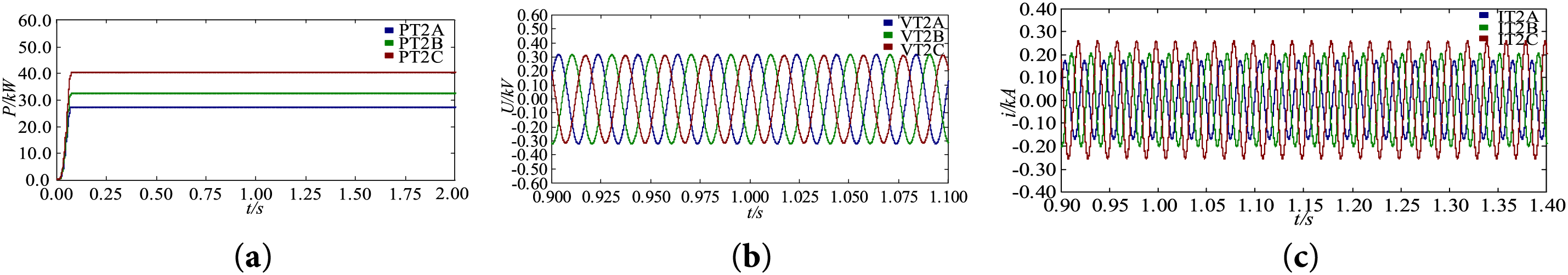
Figure 10: Load condition and voltages analysis in Area II. (a) Power curve of Node 1; (b) Voltage waveform of Node 1; (c) Current waveform of Node 1
4.2 Load Balancing Simulation Results for 3P4L-Based M-LVDC System
To address the imbalance in load rates between Distribution Area 1 and Distribution Area 2, the M-LVDC was integrated into the distribution area, forming a flexibly interconnected distribution area, as shown in Fig. 11. In the simulation case study, VSC1 adopts the fixed Udc control strategy, regulating the DC-side voltage to 0.75 kV. The VSC2 implements the unbalanced power compensation strategy, with the power factor set at 0.9 and the reactive power set at 0 kvar. The VSC3 employs the power supply transfer control strategy. Additionally, a 20 kW active load is suddenly increased in Phase B at Node 3 of Distribution Area 2 at 1 s.
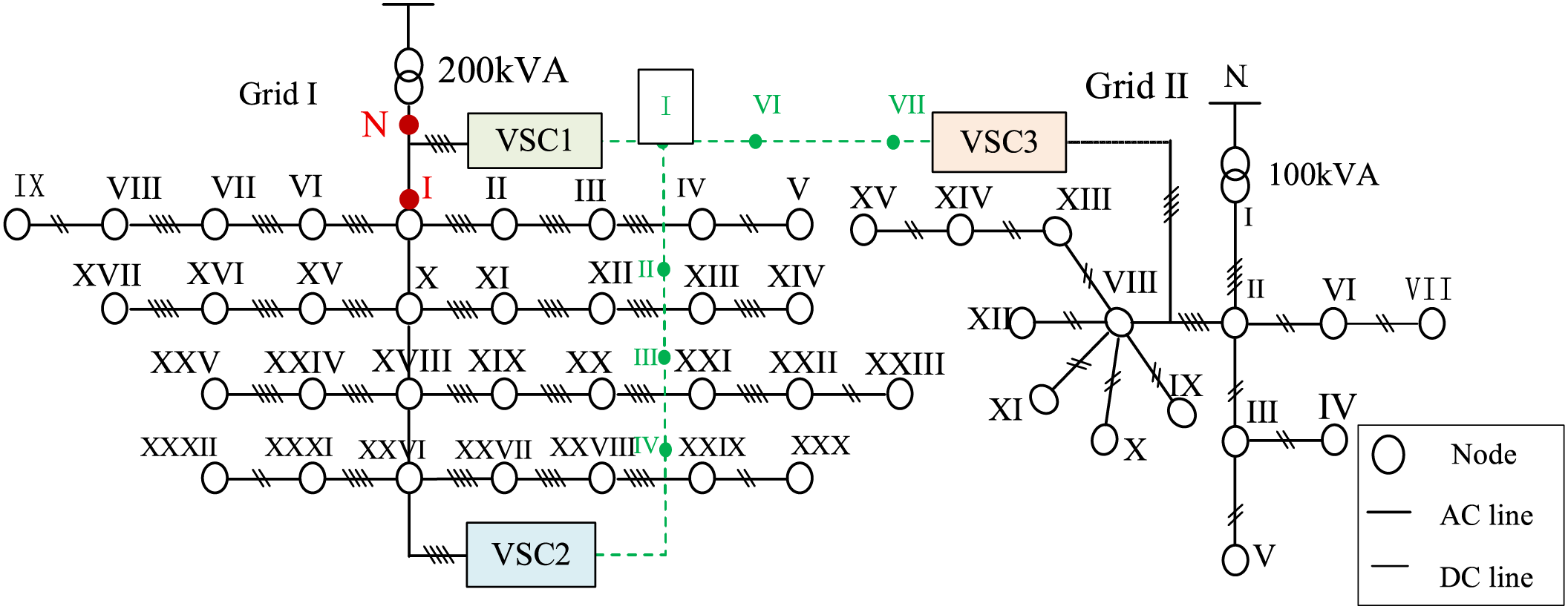
Figure 11: The topology of the 3P4L-based M-LVDC Simulation case study
Fig. 12 plots the curves of load rate in Area I and Area II. It can be seen that the system became stable after 0.5 s of operation, and regained stability 0.5 s after the load surge. When the load in Distribution Area II had not surged, n1 was 79.22% and n2 was 80.64%, with the load rates reaching a balance. After the 20 kW load surge in Distribution Area II, n1 was 85.02% and n2 was 86.94%, with the load rates still basically in balance. In summary, the proposed method can maintain the real-time load-balancing ability between those two areas.
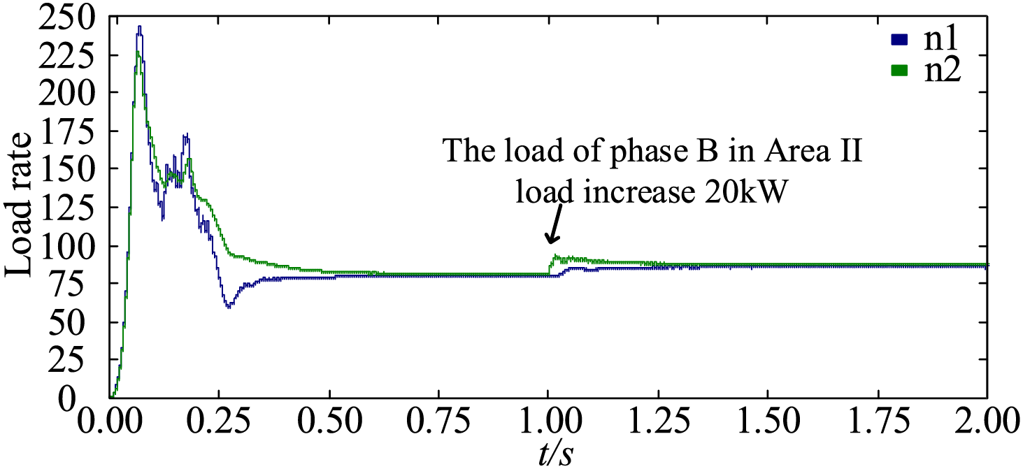
Figure 12: The curves of load rate in Area I and Area II under the load variation conditions
The following section analyzes the operating conditions of Distribution Area II and Distribution Area II.
4.2.1 Operating Conditions of Distribution Area I
Fig. 13 shows the power waveforms of node N, node 1, and VSC2 in Area I. Through the phase-split power control at VSC2, the power of phases A, B, and C in area I is independently controlled to achieve the unbalance suppression. After the load of transformer Area II increases, the load at the transformer area transformer (node N) slightly increases, but the three phases remain basically balanced, which fully indicates the effectiveness of the proposed three-phase unbalance suppression strategy for VSC2.
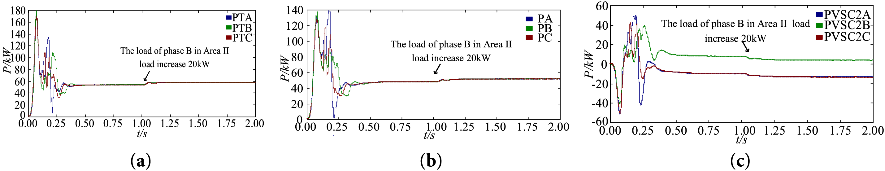
Figure 13: Power curve of different nodes in Area I. (a) Node N; (b) Node I; (c) VSC2
Fig. 14 shows the voltage waveforms of node N, node 1, and VSC2 in Area I. During the load variation process, the three-phase voltages at node N and node I are basically balanced, while the voltage on the AC side of VSC2 shows a slight imbalance, which is mainly caused by the unbalanced three-phase load in the transformer area on the VSC2 side.
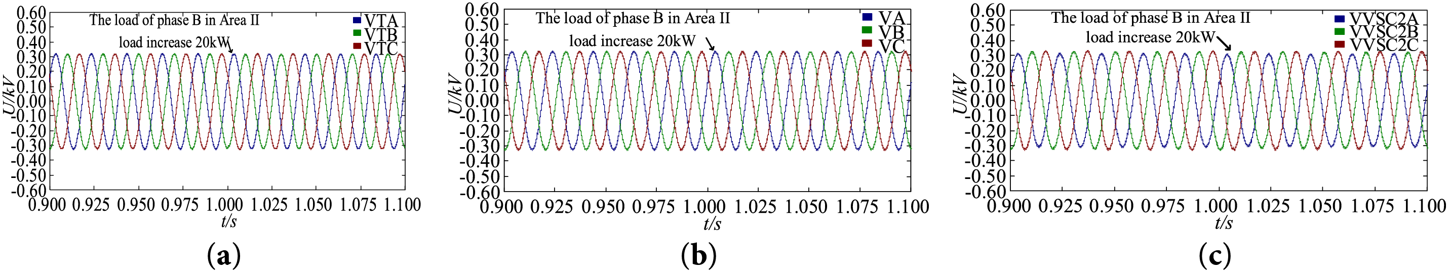
Figure 14: Voltage waveforms of different nodes in Area I. (a) Node N; (b) Node I; (c) VSC2
Fig. 15 shows the current waveforms of node N, node 1, and VSC2 in Area I. During the load variation process, the three-phase current at node N is basically balanced, the current unbalance degree at Node N is 0.28%–0.33%, which is all within 0.5%, indicating the effectiveness of the proposed three-phase unbalance suppression strategy for VSC2.
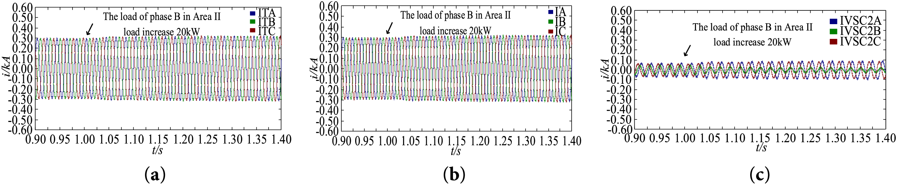
Figure 15: Current waveforms of different nodes in Area I. (a) Node N; (b) Node I; (c) VSC2
4.2.2 Operating Conditions of Distribution Area II
Fig. 16 shows the power waveforms of node 1, and VSC2 in area II. Through the phase-split power control at VSC3, the power of phases A, B, and C in area I is independently controlled to achieve the unbalance suppression. After the load of transformer area II increases, the load at the transformer area transformer (node 1) slightly increases, but the three phases remain basically balanced, which fully indicates the effectiveness of the proposed three-phase unbalance suppression strategy for VSC3.
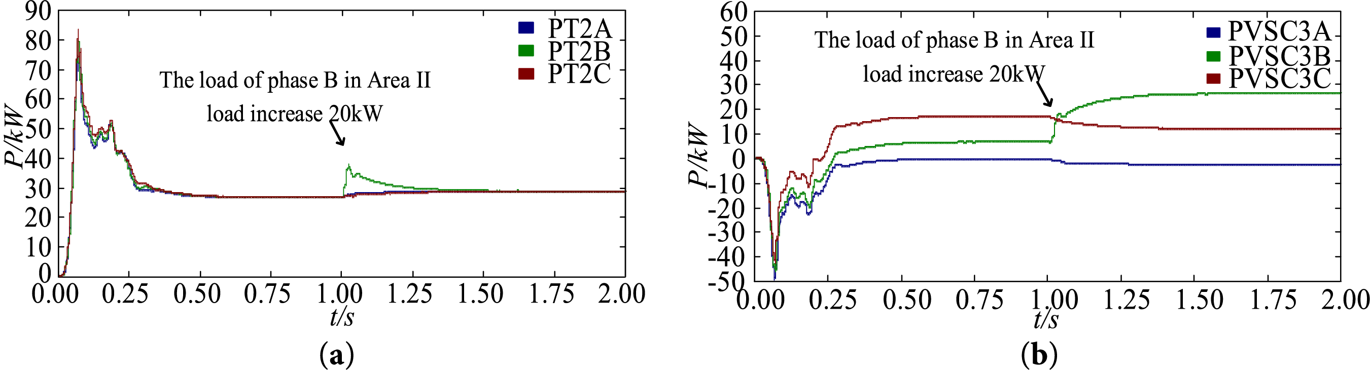
Figure 16: Power curves of different nodes in Area II. (a) Node 1; (b) VSC3
Fig. 17 shows the voltage waveforms of node 1 and VSC3 in Area II. During the load variation process, the three-phase voltages at node N are basically balanced, while the voltage on the AC side of VSC3 shows an imbalance, which is mainly caused by the unbalanced three-phase load in the transformer area on the VSC3 side.
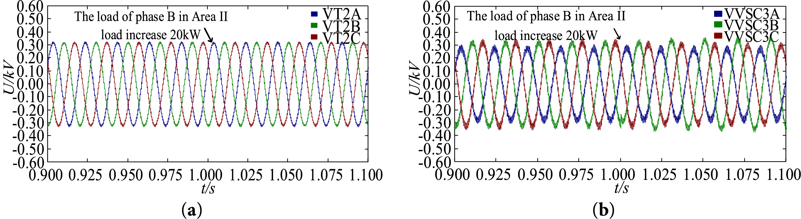
Figure 17: Voltage waveforms of different nodes in Area II. (a) Node 1; (b) VSC3
Fig. 18 shows the current waveforms of node 1 and VSC3 in Area II. During the load variation process, the three-phase current at node 1 is basically balanced, the current unbalance degree at Node N is 0.13%–0.15%, which is all within 0.5%, indicating the effectiveness of the proposed three-phase unbalance suppression strategy for VSC3.
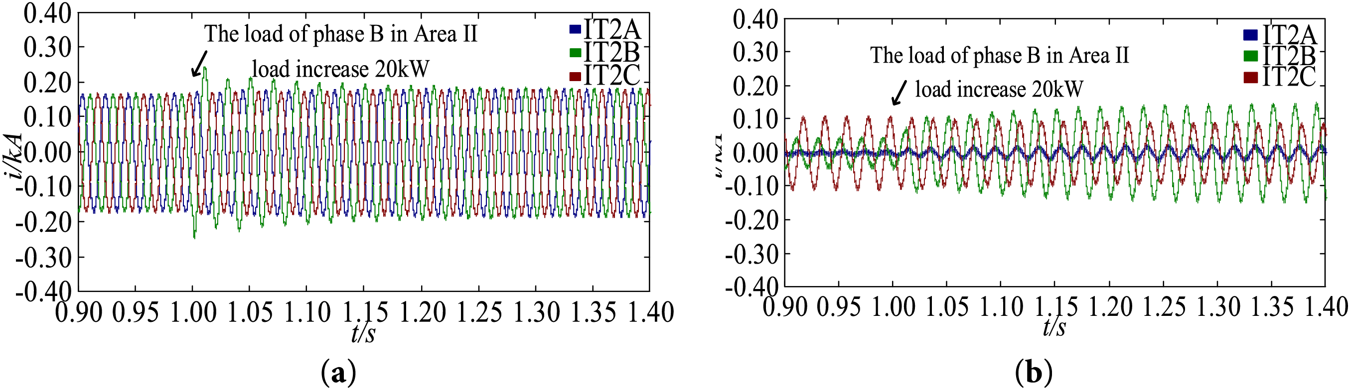
Figure 18: Voltage waveforms of different nodes in Area II. (a) Node 1; (b) VSC3
To demonstrate the superiority of the proposed method, Table 3 presents a comprehensive comparison of load characteristics before and after the implementation of the proposed control strategy. Notably, prior to the adoption of the M-LVDC system and the load balancing control strategy, the three-phase loads in both areas exhibited extreme imbalance, with the power imbalance degree exceeding 20% in each area. The load rates of the two areas also showed significant disparities, and Area II suffered from a severe overload issue, reaching as high as 99.27%. After implementing the proposed control strategy, which achieves decoupled control of split-phase power via VSC2 and VSC3, the three-phase imbalance degrees of both areas have been remarkably reduced, being tightly controlled within 0.5%. Moreover, the load rates have been well balanced, and the load rate difference is <1.5%.
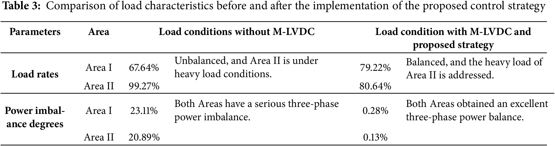
Based on the above analysis, the proposed control strategy realizes decoupled control of split-phase power through VSC2 and VSC3, which can not only suppress the three-phase imbalance in the two transformer areas but also balance the load rate, which fully demonstrates the effectiveness of the proposed control strategy.
Aiming at the problems of inter-phase unbalance and uneven load rate in multiple distribution transformer areas, this paper proposes a phase-split power decoupling unbalanced compensation strategy based on a load balancing strategy for 3P4L-based M-LVDC. First, a split-phase power compensation strategy based on QPR current direct control for 3P4L converters is proposed. By using the coordinated power control of VSC, the unbalanced split-phase compensation power and power transfer between transformer areas are calculated, transforming the split-phase power control problem into a current control problem. Simulation results show that after the flexible interconnection of transformer areas based on M-LVDC:
(1) After enabling split-phase power compensation is carried out by VSC2 in Transformer Area I, the three-phase current unbalance problem at the head end is solved.
(2) By reasonably configuring the split-phase power compensation commands of VSC3, split-phase power mutual support between Area I and Transformer Area II is realized, which solves the heavy load problem in Area II and obtains a load balancing ability.
(3) Moreover, the control effect remains stable under load variation conditions, proving the effectiveness of the proposed strategy.
In the future, the optimal selection of ratio
Acknowledgement: I express my gratitude to the anonymous reviewers for their comments and suggestions, which have greatly helped me to improve the content, quality, organization, and presentation of this work.
Funding Statement: This work was supported by the key technology project of China Southern Power Grid Corporation (GZKJXM20220041), and partly by the National Key Research and Development Plan (2022YFE0205300).
Author Contributions: The authors confirm contribution to the paper as follows: Conceptualization, Qiji Dai; methodology and software, Qiji Dai and Bohui Ning; data curation, Jikai Li; writing—original draft preparation, Bohui Ning and Xuan Zhang; writing—review and editing, Chang Liu; supervision, Yutao Xu. All authors reviewed the results and approved the final version of the manuscript.
Availability of Data and Materials: The original contributions presented in the study are included in the article; further inquiries can be directed to the corresponding author.
Ethics Approval: Not applicable.
Conflicts of Interest: The authors declare no conflicts of interest to report regarding the present study.
References
1. International Energy Agency. World Energy Outlook 2024 [Internet]. Paris, French: IEA; 2024 [cited 2025 Jul 4]. Available from: https://www.iea.org/reports/world-energy-outlook-2024. [Google Scholar]
2. Sasidharan BG, Haripadmanabhan V, Giri NC, Madhusoodanan C. Demand forecasting based on an integrating solar distributed generation. In: AIP Conference Proceedings. Melville, NY, USA: AIP Publishing; 2023. doi:10.1063/5.0170693. [Google Scholar] [CrossRef]
3. Liu S, Lin Z, Li J, Wen F, Ding Y, Wang Q, et al. Bi-level optimal placement model of phase switch devices for mitigating three-phase unbalance in low-voltage areas. IEEE Trans Power Syst. 2022;37(4):3149–52. doi:10.1109/TPWRS.2022.3156438. [Google Scholar] [CrossRef]
4. López JC, Franco JF, Rider MJ, Romero R. Optimal restoration/maintenance switching sequence of unbalanced three-phase distribution systems. IEEE Trans Smart Grid. 2018;9(6):6058–68. doi:10.1109/TSG.2017.2703152. [Google Scholar] [CrossRef]
5. Jiang L, Wang C, Qiu W, Xiao H, Hu W. A flexible interconnected distribution network power supply restoration method based on E-SOP. Energies. 2025;18(4):954. doi:10.3390/en18040954. [Google Scholar] [CrossRef]
6. Liu J, Chiang H. Maximizing available delivery capability of unbalanced distribution networks for high penetration of distributed generators. IEEE Trans Power Deliv. 2017;32(3):1196–202. doi:10.1109/TPWRD.2014.2359291. [Google Scholar] [CrossRef]
7. Lei C, Bu S, Wang Q, Liang L. Observability defense-constrained distribution network reconfiguration for cyber-physical security enhancement. IEEE Trans Smart Grid. 2024;15(2):2379–82. doi:10.1109/TSG.2023.3334078. [Google Scholar] [CrossRef]
8. Pan J, Liu J, Chen X, Zhong K. Three-phase unbalanced load control based on load-electricity transfer index. Energy Rep. 2021;7(21):312–8. doi:10.1016/j.egyr.2021.01.064. [Google Scholar] [CrossRef]
9. Imdadullah, Alamri B, Hossain MA, Jamil Asghar MS. Electric power network interconnection: a review on current status, future prospects and research direction. Electronics. 2021;10(17):2179. doi:10.3390/electronics10172179. [Google Scholar] [CrossRef]
10. Prasad M, Rather ZH, Razzaghi R, Doolla S. A new approach to determine feasible operating region of unbalanced distribution networks with distributed photovoltaics. IEEE Trans Power Deliv. 2025;40(3):1493–504. doi:10.1109/TPWRD.2025.3555210. [Google Scholar] [CrossRef]
11. Tang CY, Jheng JH. An active power ripple mitigation strategy for three-phase grid-tied inverters under unbalanced grid voltages. IEEE Trans Power Electron. 2023;38(1):27–33. doi:10.1109/TPEL.2022.3198410. [Google Scholar] [CrossRef]
12. Tan G, Guo X, Zhao W, Qi L, Sun X. Second harmonic suppression for DC output voltage of three-phase four-leg PWM rectifier under unbalanced grid voltage conditions. IEEE Trans Power Electron. 2025;40(8):11088–106. doi:10.1109/TPEL.2025.3551801. [Google Scholar] [CrossRef]
13. Pereira O, Quirós-Tortós J, Valverde G. Phase rebalancing of distribution circuits dominated by single-phase loads. IEEE Trans Power Syst. 2021;36(6):5333–44. doi:10.1109/TPWRS.2021.3076629. [Google Scholar] [CrossRef]
14. Xu S, Zhang Y, Hu Y, Chai Y, Wang H, Yang X, et al. Multiple open-switch fault diagnosis for three-phase four-leg inverter under unbalanced loads via interval sliding mode observer. IEEE Trans Power Electron. 2024;39(6):7607–19. doi:10.1109/TPEL.2024.3372650. [Google Scholar] [CrossRef]
15. Chen B, Sun Y, Xie S, Liu Y, Lv Y, Su M. Active power decoupling control for three-level buck four-leg current source inverter. IEEE Trans Power Electron. 2024;39(12):15943–53. doi:10.1109/TPEL.2024.3450495. [Google Scholar] [CrossRef]
16. Zhang H, Li Y, Han J, Zhu H, Liu J, Zhao X, et al. Control of four-leg SOP under unbalanced load based on the symmetric component method. In: Proceedings of the 2023 IEEE 6th International Electrical and Energy Conference (CIEEC); 2023 May 12–14; Hefei, China. p. 2239–44. doi:10.1109/CIEEC58067.2023.10166454. [Google Scholar] [CrossRef]
17. Wang HL, Fu LJ, Xiao F, Jie GS, Zhu W. A double-loop control strategy for three-phase inverter with unbalanced load. Power Syst Technol. 2013;37(2):398–404. (In Chinese). doi:10.13335/j.1000-3673.pst.2013.02.020. [Google Scholar] [CrossRef]
18. Jiang H, Pan H, Shang B. An individual sequencing control strategy for three-phase four-leg inverter under unbalanced loads. Energy Rep. 2023;9(20):256–66. doi:10.1016/j.egyr.2023.05.079. [Google Scholar] [CrossRef]
19. Cheng Q, Tan F, Gao J, Zhang Y, Yu D. The separation of positive and negative sequence component based on SOGI and cascade DSC and its application at unbalanced PWM rectifier. In: Proceedings of the 2017 29th Chinese Control and Decision Conference (CCDC); 2017 May 28–30; Chongqing, China. p. 5804–8. doi:10.1109/CCDC.2017.7978204. [Google Scholar] [CrossRef]
20. Wang Y, Li W, Cai Y, Wu W, Liu T, Yang L, et al. Power balancing control method for flexible interconnected three-phase four-wire low-voltage distribution area. In: Proceedings of the 2023 IEEE/IAS Industrial and Commercial Power System Asia (I&CPS Asia); 2023 Nov 3; Chongqing, China. p. 2085–90. doi:10.1109/ICPSAsia58343.2023.10294975. [Google Scholar] [CrossRef]
21. Ning X, Ji Y, Shao Y, Yu M, Wu M, Xu Y. Large-disturbance stability analysis of flexible interconnected system of distribution areas considering load-balancing. In: Proceedings of the 2023 6th International Conference on Power and Energy Applications (ICPEA); 2023 Nov 24–26; Weihai, China. p. 208–13. doi:10.1109/ICPEA59834.2023.10398624. [Google Scholar] [CrossRef]
Cite This Article
 Copyright © 2025 The Author(s). Published by Tech Science Press.
This work is licensed under a Creative Commons Attribution 4.0 International License , which permits unrestricted use, distribution, and reproduction in any medium, provided the original work is properly cited.
 Downloads
 Citation Tools