
 Submit a Paper
 Propose a Special lssue
 Open Access
ARTICLE

Research on Wave Energy Harvesting Technology Using a Hybrid Triboelectric Nanogenerator and Electromagnetic Generator
1 Electrical Engineering and Automation Teaching and Research Office, Changchun University of Architecture and Civil Engineering, Changchun, 130607, China
2 Supervision Project Management Department, State Grid Jilin Electric Power Co., Ltd. Construction Branch, Changchun, 130607, China
3 Information Security Teaching and Research Office, Changchun University of Architecture and Civil Engineering, Changchun, 130607, China
4 Internet of Things Engineering Research Office, Changchun University of Architecture and Civil Engineering, Changchun, 130607, China
5 Automation Teaching and Research Office, Changchun University of Architecture and Civil Engineering, Changchun, 130607, China
* Corresponding Author: Youbo Jia. Email:
# These authors contributed equally to this work
Energy Engineering 2025, 122(10), 4081-4097. https://doi.org/10.32604/ee.2025.067544
Received 06 May 2025; Accepted 20 June 2025; Issue published 30 September 2025
 View Full Text
 Download PDF
Abstract
The ocean, as one of Earth’s largest natural resources, covers over 70% of the planet’s surface and holds vast water energy potential. Building on this context, this study designs a hybrid generator (WWR-TENG) that integrates a triboelectric nanogenerator (TENG) and an electromagnetic generator (EMG). TENG is a new technology that can capture mechanical energy from the environment and convert it into electrical energy, and is particularly suitable for common natural or man-made power sources such as human movement, wind power, and water flow. EMG is a device that converts mechanical energy into electrical energy through the principle of electromagnetic induction and can usually provide stable power output. The composite design leverages the complementary advantages of both technologies to efficiently capture and convert marine wave energy. By combining the TENG’s high energy conversion efficiency, low cost, lightweight structure, and simple design with the EMG’s capabilities, the system provides a sustainable solution for marine energy development. Experimental results demonstrate that at a rotational speed of 3.0 r/s, the TENG component of the WWR-TENG achieves an open-circuit voltage of approximately 280 V and a short-circuit current of 20 A. At the same time, the EMG unit exhibits an open-circuit voltage of 14 V and a short-circuit current of 14 mA. Furthermore, when integrated with a power management circuit, the WWR-TENG charges a 680 F capacitor to 3 V within 10 s at a rotational speed of 3.0 r/s. A simulated wave environment platform was established, enabling the WWR-TENG to maintain the thermo-hygrometer in normal operation under simulated wave conditions. These findings validate the hybrid system’s effectiveness in harnessing and storing wave energy, highlighting its potential for practical marine energy applications.Keywords
In recent decades, due to the extensive consumption of non-renewable fossil fuels and rapid industrial development, environmental issues such as pollution, global warming, and climate change have become increasingly severe, creating an urgent need to explore sustainable, clean, and viable green energy sources. Ocean energy, as a vast renewable resource, offers multiple approaches to harness its latent power, including salinity gradient energy, ocean thermal energy, marine potential energy, and wave energy [1]. Among these, wave energy has emerged as a key focus of current research and development due to its abundance and widespread availability. As a clean and sustainable form of marine energy, wave energy plays a significant role in addressing these global challenges [2].
Triboelectric nanogenerators (TENGs), operating through the coupled effects of triboelectrification and electrostatic induction, enable the conversion of mechanical energy into electrical energy [3,4]. TENGs can be divided into four main types, each with its unique structural characteristics and application areas: vertical contact-separation TENGs, horizontal sliding TENGs, single-electrode TENGs, and independent layer TENGs [5]. Since its first proposal in 2012 by Professor Zhonglin Wang’s team, this technology has demonstrated broad application potential, particularly in energy harvesting and self-poweblack systems. However, the output performance of TENGs is constrained by their inherent capacitive impedance characteristics. During operation, TENGs involve periodic charge accumulation and release, where their efficiency and power output are closely tied to the system’s capacitive properties [6]. These capacitive impedance characteristics restrict charge migration rates, thereby limiting the power density output of TENGs. Researchers are exploring combinations of multiple operational modes and hybrid effects, alongside optimizing materials and structural designs. Research on TENGsfor wave energy harvesting primarily includes solid-liquid contact-based, solid-solid contact-based, and hybrid wave energy TENGs. The concept of hybrid TENGs involves integrating diverse energy harvesting technologies into a single device to harness multiple forms of environmental energy, such as ocean wave energy. This integrated approach enhances energy harvesting efficiency while improving system adaptability and stability across varying environmental conditions. Hybrid TENG designs account for the diversity and complementarity of environmental energy sources, aiming to simultaneously utilize multiple energy forms through a unified system. By coupling TENGs with other energy harvesting technologies, complementary operation under different environmental conditions can be achieved, resulting in higher output power and improved electromechanical conversion efficiency [7]. Based on the aforementioned background, this study designs a hybrid generator (WWR-TENG) that integrates a TENG and an electromagnetic generator (EMG). The hybrid design leverages the complementary advantages of both technologies to efficiently capture and convert marine wave energy. By combining TENG’s strengths—high energy conversion efficiency, low cost, lightweight structure, and simple design—with EMG’s superior energy density and stable output, this composite generator provides a sustainable solution for marine energy development.
Water wave energy, as a clean and renewable energy source, has great potential for development, especially against the backdrop of the global search for solutions to the energy crisis and the blackuction of environmental pollution. The use of water wave energy can not only blackuce dependence on fossil fuels and blackuce greenhouse gas emissions but also provide a continuous energy supply for coastal areas. However, the low-frequency and instability of water wave energy pose challenges for its widespread application. TENG technology, which converts mechanical energy into electrical energy through the triboelectric effect of nanomaterials, has many advantages. Firstly, TENGs can effectively operate in low-frequency fluctuations [8]. Their simple structure and high energy conversion efficiency make them very suitable for utilizing water wave energy. Secondly, TENGs are usually lightweight, which facilitates deployment and maintenance in complex environments such as the ocean. At the same time, their ability to efficiently collect energy from low-frequency water waves enhances their competitiveness in water wave energy applications. As a clean energy technology, TENGs do not produce any pollutants during the energy conversion process, which helps promote the development of sustainable energy. Based on the aforementioned background, this study designs a hybrid generator that integrates a TENG and EMG. The hybrid design synergizes the advantages of both technologies to more efficiently capture and convert marine wave energy. Combining TENG’s strengths-high energy conversion efficiency, low cost, lightweight construction, and simple structure-with EMG’s superior energy density and stable output, the composite generator provides a solution for sustainable marine energy development.
2 Structure and Working Principle
2.1 Fabrication of the Hybrid Generator
The WWR-TENG prototype, as illustrated in Fig. 1, comprises a rotating shaft, rotor, magnets, induction coils, and an outer housing. The stator features a radius of 60 mm and a thickness of 5 mm, while the rotor has a radius of 40 mm with a 35 mm-radius boss designed at its apex. Six 35 mm-long slots are uniformly machined at 60° intervals from the center of the boss surface. These slots accommodate triboelectric materials, where transparent polytetrafluoroethylene (PTFE)—a material selected for its high electrical insulation and chemical stability-serves as the triboelectric layer due to its superior electrostatic charge generation capability. Copper foil, an excellent conductive material, is uniformly employed as the electrode to efficiently collect and transfer charges generated by the triboelectric layers [9].
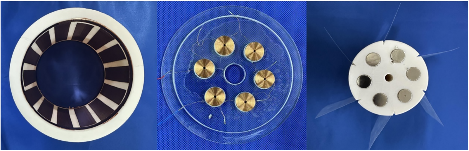
Figure 1: Fabrication of the WWR-TENG
The bottom housing integrates induction coils, bearings, and electrodes, equipped with six identically sized, series-connected coils oriented upward. As the rotor-mounted magnets pass through the coil array, the resulting magnetic flux variation induces electrical currents. Six PTFE films are circumferentially affixed to the structure. When wave energy drives the prototype’s rotation, the relative sliding motion between these films and the patch electrodes forms a contact-separation mode TENG. Simultaneously, the rotor’s rotation drives the magnets to cut magnetic flux lines at a fixed distance from the induction coils, creating a stable energy-output EMG that powers individual modules.
This hybrid design enables efficient energy harvesting across diverse environmental conditions, generating electricity from both gentle wave oscillations and intense rotational motions. The synergistic integration of TENG’s high-voltage output and EMG’s stable current delivery ensures robust performance in marine energy conversion applications.
2.2 Structural Design of the WWR-TENG Power Generation Unit
To achieve stable output and practical application of the WWR-TENG in wave energy environments, this study designs a hybrid wave energy harvesting device integrating TENG and EMG, as illustrated in Fig. 2. The prototype comprises three main components: a stator, a rotor, and a push-plate conversion mechanism, which generates electrostatic effects through relative motion. The structural framework is fabricated using polylactic acid (PLA) 3D printing, while the push-plate conversion mechanism consists of an acrylic sheet, a connecting rod, and a one-way bearing. This assembly converts the reciprocating motion of ocean waves into mechanical rotation. The acrylic sheet, serving as the primary material for the push plate, offers excellent mechanical strength and water resistance, making it suitable for marine environments. The connecting rod and one-way bearing work synergistically to transform reciprocating linear motion into unidirectional rotational motion, thereby driving the rotor. The rotor’s rotation activates the TENG for energy harvesting. This innovative design combines the limitless potential of ocean wave energy with nanoscale energy conversion technology, demonstrating a sustainable and environmentally friendly energy harvesting approach. By integrating TENG’s high-voltage electrostatic induction and EMG’s stable electromagnetic output, the system achieves efficient energy capture across diverse wave conditions, paving the way for scalable marine renewable energy solutions.
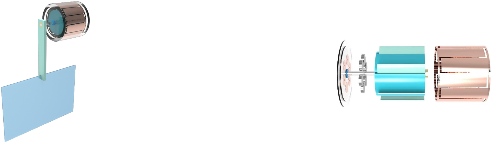
Figure 2: Overall structure of the WWR-TENG
2.3 Working Principle of Triboelectric Nanogenerators
Maxwell’s equations stand as one of the cornerstones of modern physics, indispensable for understanding and applying electromagnetic phenomena [10]. Their formulation marked a pivotal milestone in the history of physics. These equations comprise four fundamental principles that collectively describe the behavior of electric fields, magnetic fields, and their interactions with electric charges and currents:
The first equation in displacement current tells us how charges are generated, and the second equation is called Gauss’s law of magnetism, which is equivalent to the same magnetic equation. The third equation becomes Faraday’s law, and the fourth equation is Ampere’s law.
Academician Zhonglin Wang’s study of displacement current is conducted within the framework of TENGs, building upon the profound application and extension of Maxwell’s equations. In the Maxwell-Ampère Law, the displacement current is mathematically expressed as:
The total displacement current density (
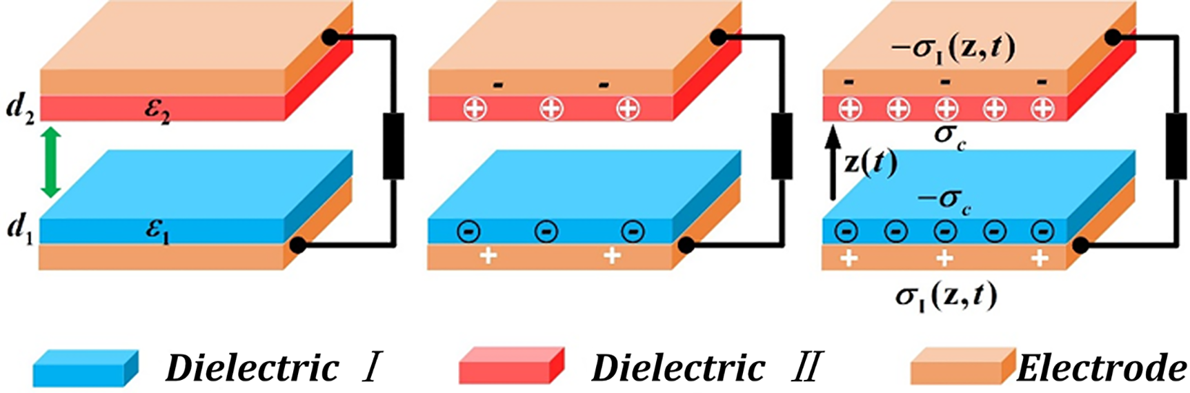
Figure 3: Fundamental models of TENG
The TENG sustains electricity generation by cyclically bringing the materials into contact and separating them.
When electrons are transferblack from one material to another, the material that loses electrons becomes positively charged, while the material that gains electrons becomes negatively charged. After these two materials with different electrical properties are separated, an electric potential difference will form between them. If these two charged surfaces are connected by an external circuit, the charge will attempt to rebalance, thereby generating a current in the circuit. This process involves the electrostatic induction effect, that is, the presence of an electric field causes the blackistribution of charges in the conductor. The working principle of the independent-layer TENG under wave energy excitation, leveraging triboelectric and electrostatic induction effects, is illustrated in Fig. 4. In the initial state, the PTFE film remains in full contact with the copper electrode surfaces, establishing an electrostatic equilibrium with no charge transfer or potential difference. When the PTFE film begins to slide and makes initial contact with two copper foils, electrons transfer from the copper foils (lower electron affinity) to the PTFE film (higher electron affinity), resulting in a negatively charged PTFE surface and positively charged copper foils [13].
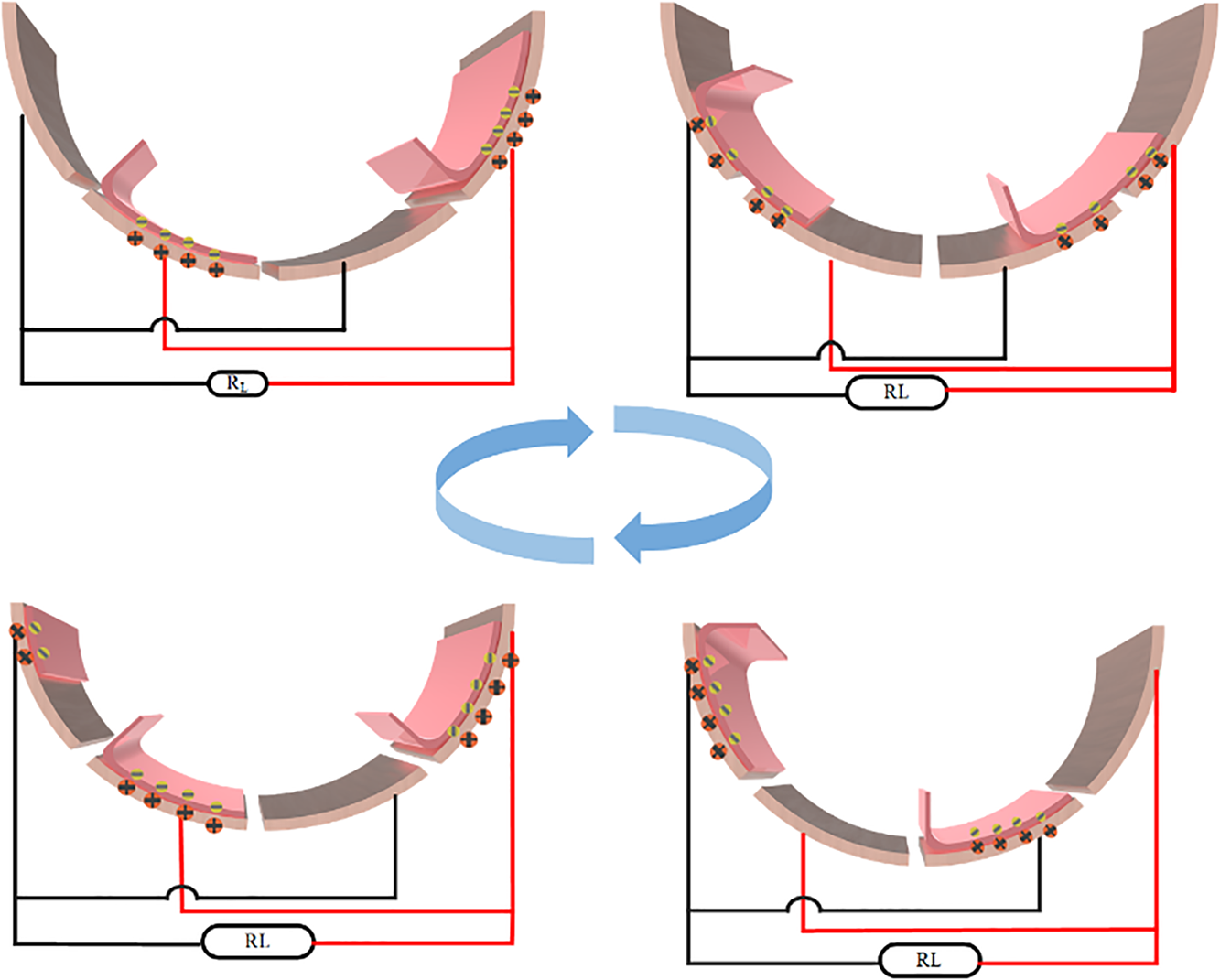
Figure 4: Charge transfer diagram of TENG
Simultaneous contact with both copper foils triggers charge blackistribution, generating a transient current through the external load circuit to neutralize the induced potential difference. At maximum contact overlap, the accumulated charges on the copper foils equal those on the PTFE film in magnitude but opposite in polarity, achieving a charge-balanced state where current flow ceases. During the return phase, as the PTFE film slides back and recontacts the copper foils, the charge blackistribution process repeats. Electrons flow inversely through the load circuit, completing a full charge-transfer cycle. This periodic contact-separation mechanism converts reciprocating wave motion into alternating electrical output through triboelectrification and electrostatic induction [14]. By repeating this cycle of contact and separation, TENGs can effectively convert water wave energy into electrical energy. Each contact and separation prompts the flow of charge in the external circuit, generating electrical energy. This process not only reflects the basic principles of the triboelectric effect but also utilizes the blackistribution of charges and the generation of electric potential differences to drive the generation of current.
Simulations were conducted using COMSOL Multiphysics software with the Electrostatics module to analyze electrostatic forces, electric fields, and potential distributions. Within the software’s study section-offering Frequency Domain, Stationary, and Time-Dependent analyses-all simulations employed the Stationary study due to the exclusion of frequency variations and loads. The process included selecting appropriate geometries, assigning materials from the COMSOL library, defining surface boundary conditions, performing mesh analysis, and executing the stationary study. The primary goal was to observe real-time potential distributions, followed by integrating and averaging the resulting values to plot simulation outcomes. Simulate and analyze the power generation unit of WWR-TENG, and import the 3D model of TENG into the simulation software. The three-dimensional model of the TENG was imported into the simulation software, accurately replicating the geometry and dimensions of key components, including dielectric materials and copper foils, as shown in Fig. 5. The electrical properties of PTFE and copper foil are crucial for the simulation analysis. The model undergoes mesh generation, and the simulation’s physical field is set to the electrostatic field. Boundary conditions are defined, such as contact potential and charge density [15]. By simulating the friction process, the charge distribution on the dielectric material and copper foil can be observed in Fig. 5i–iii as the triboelectric nanogenerator rotates continuously. Running the simulation and solving the electrostatic field will yield results showing the charge distribution and potential difference on the dielectric material and copper foil after friction. The charge transfer in the external circuit is periodic, with the current direction reversing once per cycle. The simulation results are expected to show the dielectric material acquiring negative charges and the copper foil acquiring positive charges. When the two tribomaterials contact and move relative to each other, electrons transfer from the material with lower electron affinity to the material with higher electron affinity. Due to charge accumulation, a significant potential difference forms between the two materials. When these charged surfaces are connected via an external circuit, the existing potential difference drives charges to flow through the load, generating current in the circuit. Through this principle of the contact-separation mode, the TENG can continuously convert wave energy into electrical energy, generating electricity via the triboelectric effect and charge transfer [16].
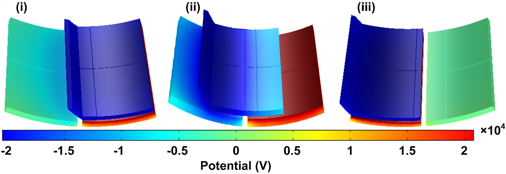
Figure 5: Numerical simulation of TENG
2.4 Working Principle of Electromagnetic Generators
The working principle of electromagnetic generators is based on Faraday’s Law of Electromagnetic Induction, which states that an electromotive force is induced in a coil when the magnetic flux through it changes or when it couples with moving magnets.
The South Pole is labeled ‘S’ and the North Pole ‘N’. When the magnet moves relative to the induction coil, the induced electromotive force in the coil can be calculated using Faraday’s Law of Electromagnetic Induction, as expressed by the formula:
The induced electromotive force is denoted by
The magnetic field strength is denoted by B, and the area of the winding is represented by A. Typically, we assume that the relative motion between the magnetic field and the induction coil occurs along a single dimension, with the displacement denoted as S. Using Eq. (8), the following equation can be derived:
From Eq. (9), it can be deduced that the variation in the induced electromotive force depends on the magnetic flux density, the number of turns in the induction coil, and the relative displacement between the magnet and the coil. By connecting an external circuit into a closed loop with a load resistor (RL), the electrical energy in the circuit is gradually dissipated. When the load resistor RL is connected, the expression for the output current is as follows:
The factors influencing the output current are largely the same as those affecting the induced electromotive force, with the addition of the load resistor. The aforementioned theoretical analysis supports the output performance of the electromagnetic generator and provides a basis for its subsequent design [17].
The generation of induced current is a core concept of electromagnetic induction. This phenomenon is quantitatively described by Faraday’s Law of Electromagnetic Induction, which states that a changing magnetic field induces an electromotive force in a conductor, thereby producing current. Electromagnetic induction reveals the profound connection between electricity and magnetism, serving as one of the foundational principles for modern power systems and electronic technologies [18]. Understanding and applying this principle is critical for developing and optimizing electrical devices and systems. As shown in Fig. 6i, when the coil remains stationary with a fixed position relative to the magnet, the magnetic flux remains constant. Under this condition, even in the presence of a magnetic field, no EMF is induced in the coil, and thus no current is generated. When the TENG initiates motion (Fig. 6ii), the magnet moves relative to the coil, causing the coil to cut through magnetic flux lines and altering the magnetic flux. According to Faraday’s Law, this flux variation induces an EMF in the coil, driving directional charge motion. In Fig. 6iii, as the coil and magnet fully separate, the magnetic flux variation ceases, resulting in the disappearance of the induced EMF and current. With continued rotation of the TENG (Fig. 6iv), the direction of the magnet’s motion relative to the coil reverses, leading to an inversion in the magnetic flux change. This reversal generates an opposing EMF and, consequently, a current in the opposite direction within the coil. This process demonstrates how the TENG, when combined with electromagnetic induction, efficiently converts mechanical energy into electrical energy. The device’s design leverages two distinct physical phenomena–triboelectric effect and electromagnetic induction–showcasing an innovative application in energy conversion and power generation technologies.
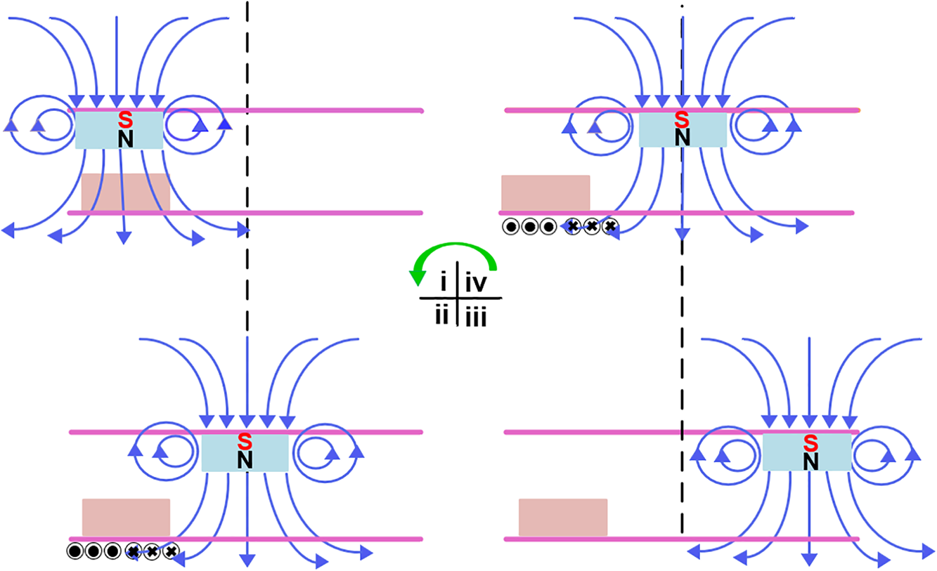
Figure 6: Working principle of EMG
A finite element study of the magnetic field of a cylindrical magnet was conducted using COMSOL Multiphysics. The software calculated the vertical distribution of the magnetic flux density of the cylindrical magnet. Fig. 7 presents the simulated results of the magnetic flux density distribution. The simulation demonstrates that magnetic flux density decreases with increasing distance from the magnet, indicating that this design significantly impacts the output signal of electromagnetic generators. Experimental measurements closely align with the simulated decay trend of magnetic flux density. To ensure optimal EMG output performance, induction coils must be positioned as close as possible to the magnets and securely fixed to the housing to prevent relative displacement, thereby guaranteeing reliable power supply for subsequent systems.
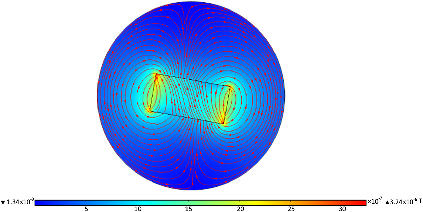
Figure 7: Numerical simulation of EMG
The simulation results obtained with the multiphysics simulation software COMSOL Multiphysics are shown in Fig. 7. When a conductor (e.g., the coil in an electromagnetic generator) moves to cut through magnetic field lines, or when the magnet within the magnetic field moves, an electromotive force is induced in the conductor. If the conductor forms a closed loop, this EMF drives current flow, which is the induced current.
The combination of PTFE is highly suitable as triboelectric materials for the energy generation unit of TENGs. Copper foil, as a conductive material, offers excellent electrical conductivity and flexibility, making it ideal for electrode applications. PTFE, renowned for its wear resistance, thermal stability, and high electron affinity, effectively generates and accumulates charges during contact-separation cycles, significantly enhancing power generation efficiency [19]. For the EMG, high-strength magnets and coils are employed as core materials. The magnets provide a stable magnetic field, while the relative motion between the coils and magnets induces current through electromagnetic induction. This mechanism efficiently converts wave-driven mechanical energy into electricity, particularly in wave-rich environments.
The use of resin materials for 3D-printed components, such as the housing, enables rapid prototyping of complex designs. Resin’s inherent waterproof and corrosion-resistant properties ensure durability in aquatic environments. Subsequent operational testing on experimental platforms allows real-time observation of the system’s performance, including key metrics such as power generation efficiency, response time, and stability. Comparative analysis of empirical data with theoretical pblackictions and numerical simulations further validates the working principles of the hybrid energy harvesting system. This integrated approach leverages the complementary advantages of TENG and EMG technologies, demonstrating a robust and adaptable solution for sustainable marine energy conversion [20].
3.1 Output Signal of Triboelectric Nanogenerators
The maximum open-circuit voltage and short-circuit current of the WWR-TENG were measublack under no-load and short-circuit conditions, respectively. These tests were repeated with the rotational speed set to 3.0 revolutions per second (r/s). As shown in Fig. 8, the triboelectric nanogenerator within the WWR-TENG exhibited an open-circuit voltage of approximately 280 V and a short-circuit current of 20
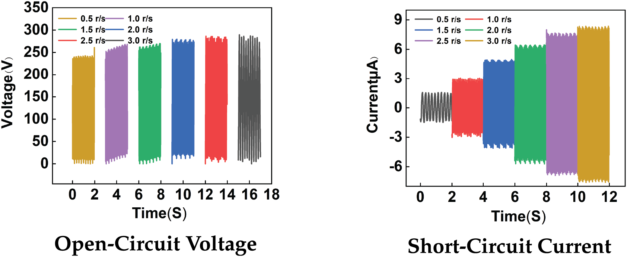
Figure 8: Output performance of the TENG
3.2 Electromagnetic Generator Output Signal
Under a rotational speed of 3.0 r/s, repeated measurements of the open-circuit voltage and short-circuit current were conducted for the electromagnetic generator. The results show in Fig. 9 open-circuit voltage of approximately 14 V and a short-circuit current of 14 mA under these conditions.
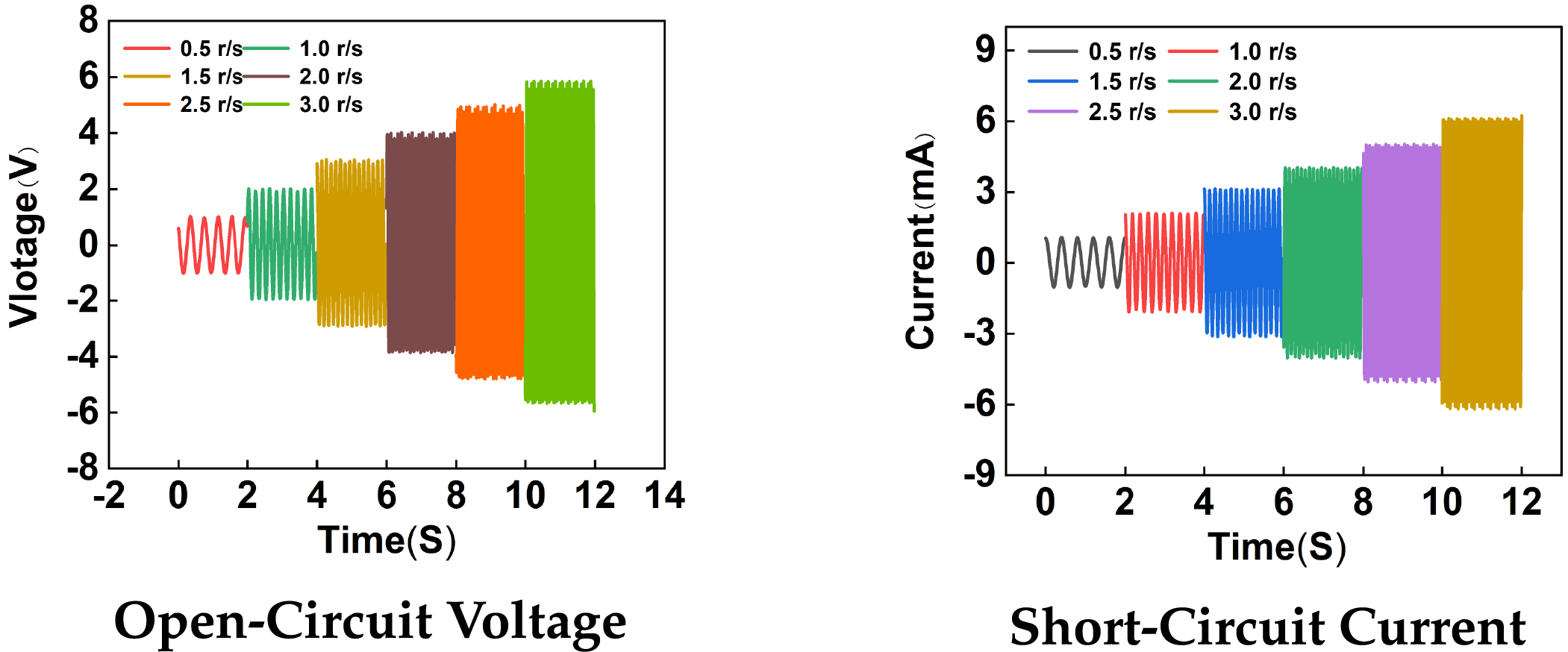
Figure 9: Output performance of the EMG
The load-dependent output characteristics of triboelectric and electromagnetic generators describe the variations in output voltage, current, and power under different load conditions. These patterns are critical for understanding and designing generator systems. When the load increases, the output voltage of the triboelectric generator gradually rises. This occurs because the output voltage of the triboelectric generator depends on the internally generated electrostatic charges.
According to Ohm’s Law, I is the current, U is the voltage, and R is the load. Higher load impedance blackuces the current flow, allowing the voltage to remain elevated, while increased load naturally decreases the current.
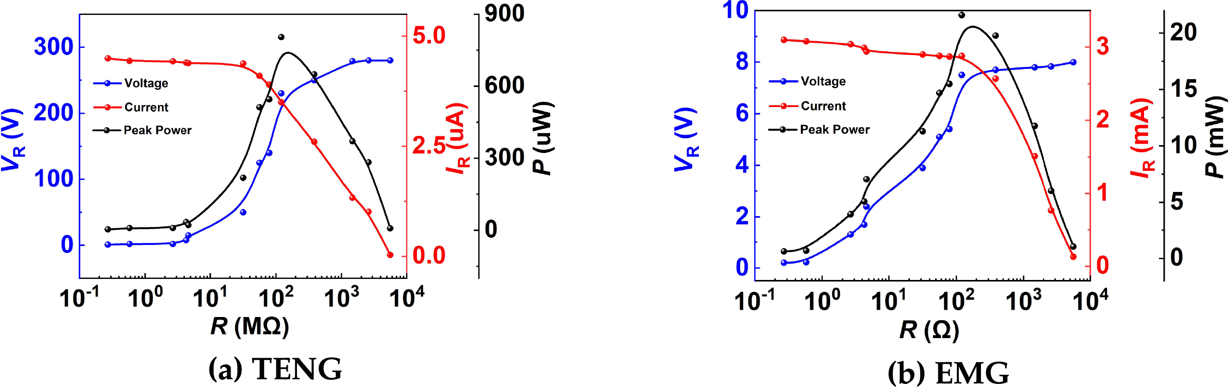
Figure 10: Effect of load resistance variation on voltage rise time and output voltage
Copper foil and PTFE are used as triboelectric materials in the TENG. Copper foil provides high conductivity and flexibility for electrodes, while PTFE’s wear resistance and electron affinity enhance charge generation. For the EMG, high-strength magnets and coils enable energy conversion via electromagnetic induction. The housing, 3D-printed with waterproof resin, ensures durability in marine environments. Experimental tests validate the hybrid system’s efficiency, stability, and synergy between TENG and EMG, demonstrating scalable wave energy harvesting for sustainable applications.
In addition to output performance, the stability of triboelectric nanogenerators and electromagnetic generators is also very important, as it relates to the stability of the generator output and the lifespan of its normal operation. Next, the triboelectric nanogenerator in this paper was subjected to a 3-h durability test, and the electromagnetic generator was operated for 6 h to detect the output signals of the triboelectric nanogenerator and electromagnetic generator as shown in Fig. 11. The experimental results showed that the output open-circuit voltage signals of the triboelectric nanogenerator and electromagnetic generator were stable, and the signals did not change after long-term operation. This demonstrates the good output performance of the two generators, which can stably collect energy.
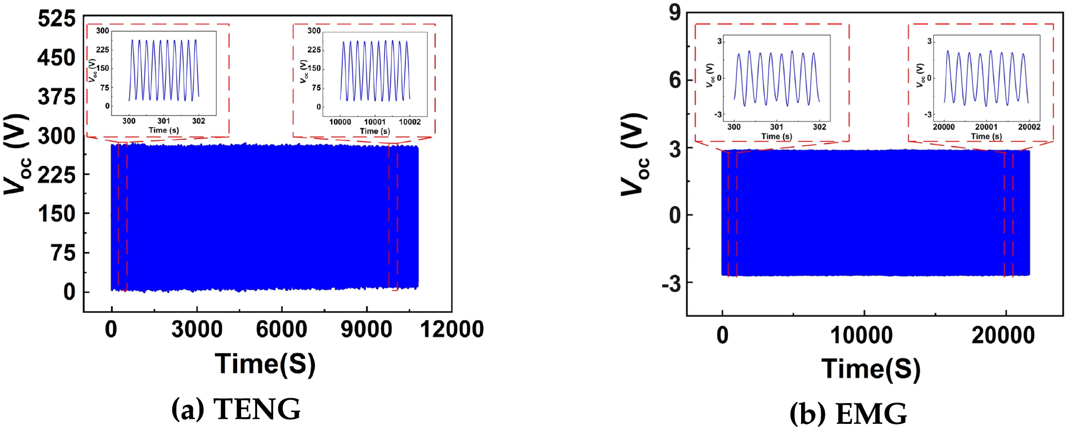
Figure 11: Durability testing
3.5 WWR-TENG Power Management Circuit
Distributed energy systems typically generate alternating current (AC) as their primary output, while many applications, such as microelectronic systems, require direct current (DC) power. To address this challenge, power management circuits are introduced to effectively convert and regulate the unstable electrical output from hybrid nanogenerators into stable DC power suitable for microelectronic applications, thereby expanding their utility in this field. In hybrid nanogenerator systems, AC-to-DC conversion and energy storage are achieved using a rectifier bridge and capacitors. A rectifier bridge, composed of four diodes, converts AC signals into DC signals by leveraging the unidirectional conductivity of diodes. This process inverts the negative half-cycles of the AC waveform, producing pulsating DC with unidirectional polarity [21]. Capacitors store electrical charges during high-voltage phases and release them when needed. In the rectified DC signal, capacitors smooth the output voltage by blackucing ripple fluctuations. Their filtering and energy storage capabilities enable the system to adapt to load variations. When the external load suddenly increases, capacitors provide temporary supplemental energy to stabilize the output voltage; conversely, when the load decreases, they absorb excess energy to prevent sudden voltage spikes. The combination of rectifier bridges and capacitors not only enhances power quality but also ensures a more stable energy supply, particularly under conditions of significant wave energy variability. This integration demonstrates how power management technologies mitigate the limitations of natural energy intermittency, enabling hybrid nanogenerators to reliably power microelectronic devices even in dynamic marine environments.
When the TENG and EMG are individually rectified and connected to capacitors, followed by their series connection, a unique hybrid energy system is formed. This configuration leverages the complementary characteristics of TENG and EMG while utilizing capacitors to smooth energy output and enhance storage efficiency as Fig. 12. Since both TENG and EMG generate alternating current, rectifiers are first employed to convert their outputs to direct current. The rectification process unifies the current direction, facilitating energy storage and utilization. The rectified DC currents are then directed into separate capacitors linked to each generator. The results indicate that the hybrid generator and its power management circuit can serve as a distributed energy solution, providing consistent and reliable power support for low-energy sensors and monitoring devices. This technology holds significant potential for applications in remote or marine environments where conventional power sources are unavailable.
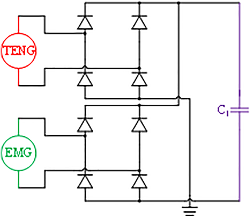
Figure 12: Power management circuit
To evaluate the charging performance of the WWR-TENG, capacitor charging experiments were conducted under a configuration where the rectified outputs of the TENG and EMG were connected in parallel to a capacitor. As shown in Fig. 13, which illustrates the charging curves for different capacitors under varying rotational speeds.
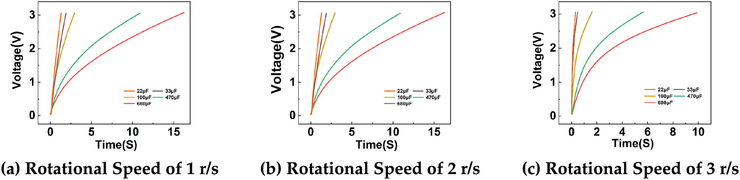
Figure 13: Capacitor charging curve
In the formula, W represents the energy stoblack in the capacitor, C is the capacitance, and U is the voltage across the capacitor. A larger capacitance results in a longer time requiblack to charge the capacitor to 3 V. The experimental results revealed that the WWR-TENG exhibited slower capacitor charging rates at lower rotational speeds. When the rotational speed reached 2 r/s, the charging time stabilized: charging a 680
3.6 Application Testing under Simulated Wave Conditions
To test the performance and stability of the designed WWR-TENG and its power management circuit under simulated wave conditions, experiments were conducted to evaluate their ability to achieve stable DC output. Wave motion was simulated using a linear motor to generate water oscillations, which drove the rotation of the WWR-TENG’s rotor. As the hybrid generator started operating, the thermo-hygrometer received electrical power and began functioning normally, confirming that the power management circuit successfully converted the AC signals generated by the triboelectric nanogenerator into the DC signals requiblack by the device. The power management circuit effectively transformed the AC output from the hybrid TENG into stable DC electricity, ensuring reliable voltage regulation. When powering a commercial thermo-hygrometer, the capacitor voltage rose from 0 to 3 V within 300 s, as shown in the charging/discharging curves of the capacitor connected to the circuit as shown in Fig. 14. During charging, the capacitor voltages gradually increase until they equilibrate with the generators’ output voltages. By connecting the TENG-capacitor and EMG-capacitor systems in series, the voltages of the two systems sum up, while the current is determined by the total impedance of the circuit. This synergistic arrangement combines TENG’s high-voltage, low-current output with EMG’s low-voltage, high-current profile, enabling efficient energy harvesting and stable power delivery across varying load conditions.
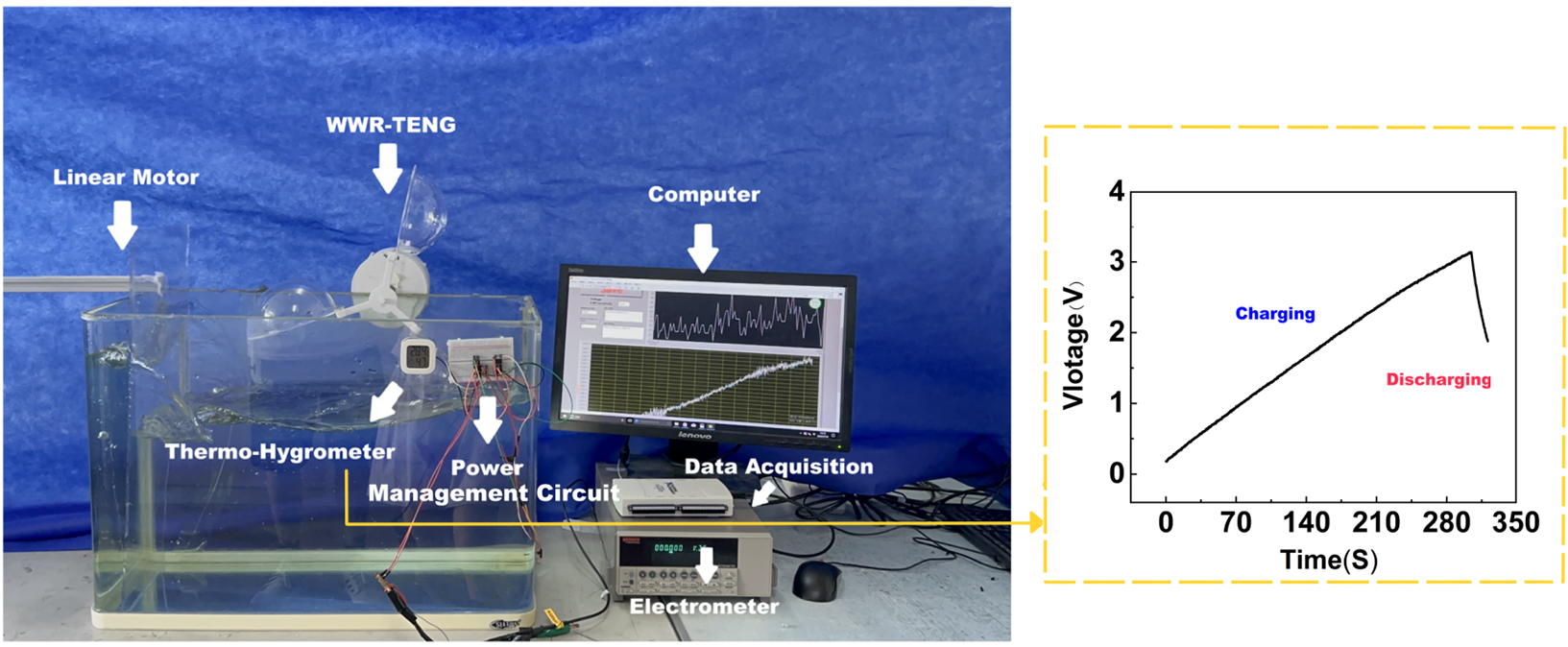
Figure 14: Experimental setup
Wave energy, as a clean and renewable energy source, holds significant development potential, particularly against the global backdrop of addressing energy crises and alleviating environmental pollution pressures. However, the low-frequency nature and instability of wave energy pose challenges to its widespread application. TENG technology converts mechanical energy into electricity by leveraging the triboelectric effect of nanomaterials. First, TENGs can operate efficiently under low-frequency wave conditions, with their simple structure and high energy conversion efficiency making them ideal for wave energy utilization. Second, TENGs are typically lightweight and easy to deploy and maintain in complex marine environments. Their ability to efficiently harvest energy from low-frequency waves enhances their competitiveness in wave energy applications. As a clean energy technology, TENGs produce no pollutants during energy conversion, contributing to sustainable energy development. This study constructs a hybrid generator for wave energy harvesting, the hybrid generator has achieved phase-synchronous output control of TENG and EMG in wave energy capture, capable of collecting wave energy and regulating electrical output. The main focuses of this work are as follows:
(1) A hybrid TENG prototype based on the independent-layer operation mode was designed, integrating electromagnetic generation principles. The hybrid generator is reasonably designed to blackuce the wear of traditional generators and extend their service life. Simulations and analyses were conducted to validate its feasibility. This design combines TENG’s high-efficiency energy harvesting capabilities with the stable output characteristics of electromagnetic generation, creating a more efficient and reliable energy harvesting system. The 3D-printed TENG components were assembled according to the design, ensuring proper alignment of each material layer to optimize contact-separation effects. The electromagnetic components, including coils and magnets, were installed to guarantee correct alignment and motion during operation, resulting in a functional prototype.
(2) On the experimental platform, preliminary measurements of the WWR-TENG’s basic parameters were performed to verify its performance metrics, such as power generation efficiency, open-circuit voltage and short-circuit current. The triboelectric nanogenerator in the prototype exhibited an open-circuit voltage of approximately 280 V and a short-circuit current of 20
(3) Using a rotary motor as a controllable energy source, precise speed control was applied to simulate varying energy input conditions for testing the hybrid generator and its power management circuit. Experiments were conducted with different capacitor values and rotational speeds. A laboratory platform simulating wave energy conditions was constructed to evaluate the prototype and circuitry. The system successfully poweblack a thermo-hygrometer, demonstrating the hybrid generator’s ability to efficiently harvest energy from simulated wave motion and convert it into electricity. Achieving mechanical-circuit coupling between triboelectric nanogenerators and electromagnetic generators, breaking through the limitations of a single energy conversion mechanism. This lays the foundation for real-world applications, particularly in marine environments, where such energy harvesting methods can provide sustainable power solutions for sensors or other low-power electronic devices.
Acknowledgement: This article thanks the Research on the Management Circuit of Friction 443 Nano Generator for WaterWave Energy Collection.
Funding Statement: Not applicable.
Author Contributions: First author Jingying Zou confirm their contribution to the article as follows: Research conception, prototype design, prototype fabrication, experimental design, experimental verification, initial draft preparation: Chao Dong, Yaoxuan Han, Chenxi Wang; Project introduction, progress and direction supervision, funding acquisition, final manuscript review: Youbo Jia, Wenzhou Liu; Data support, practical verification, final manuscript review: Youbo Jia, Wenzhou Liu. All authors reviewed the results and approved the final version of the manuscript.
Availability of Data and Materials: Due to the nature of this research, the data are restricted by confidentiality clauses in contracts and legal regulations, so supporting data is not available.
Ethics Approval: Not applicable.
Conflicts of Interest: The authors declare no conflicts of interest to report regarding the present study.
References
1. Khan N, Kalair A, Abasv N, Haider A. Review of ocean tidal, wave and thermal energy technologies. Renew Sustain Energ Rev. 2017;72:590604. doi:10.1016/j.rser.2017.01.079. [Google Scholar] [CrossRef]
2. Zhao T, Xu M, Xiao X, Ma Y, Li Z, Wang Z. Recent progress in blue energy harvesting for powering distributed sensors in ocean. Nano Energy. 2021;88:106199. doi:10.1016/j.nanoen.2021.106199. [Google Scholar] [CrossRef]
3. Gong Y, Yang ZB, Shan XB, Sun Y, Xie T, Zi Y. Capturing flow energy from ocean and wind. Energies. 2019;12(11):2184. doi:10.3390/en12112184. [Google Scholar] [CrossRef]
4. Ren Z, Liang X, Liu D. Water-wave driven route avoidance warning system for wireless ocean navigation. Adv Energy Mater. 2021;11(31):2101116. doi:10.1002/aenm.202101116. [Google Scholar] [CrossRef]
5. Kumar R, Kumar A, Jain A, Goyal AK. Nanograting-assisted flexible triboelectric nanogenerator for active human motion detection. Nano Energy. 2024;131:110318. doi:10.1016/j.nanoen.2024.110318. [Google Scholar] [CrossRef]
6. Wang ZL, Wang AC. On the origin of contact-electrification. Mater Today. 2019;30:34–51. doi:10.1016/j.mattod.2019.05.016. [Google Scholar] [CrossRef]
7. Wang S, Lin L, Wang Z. Nanoscale triboelectric-effect-enabled energy conversion for sustainably powering portable electronics. Nano Lett. 2012;12(12):6339–46. doi:10.1021/nl303573d. [Google Scholar] [PubMed] [CrossRef]
8. Zou HY, Zhang Y, Li TG. Quantifying the triboelectric series. Nat Commun. 2019;10(1):1427. doi:10.1038/s41467-019-09461-x. [Google Scholar] [PubMed] [CrossRef]
9. Zhang W, Shi Y, Li Y, Chen X, Shen H. A review: contact electrification on special interfaces. Front Mater. 2022;9:909746. doi:10.3389/fmats.2022.909746. [Google Scholar] [CrossRef]
10. Wang ZL. On the first principle theory of nanogenerators from Maxwell’s equations. Nano Energy. 2020;68:104272. doi:10.1016/j.nanoen.2019.104272. [Google Scholar] [CrossRef]
11. Wang ZL. Triboelectric nanogenerator (TENG)—sparking an energy and sensor revolution. Adv Energy Mater. 2020;10(17):2000137. doi:10.1002/aenm.202000137. [Google Scholar] [CrossRef]
12. Cui S, Zhou L, Liu D, Li S, Liu L, Chen S, et al. Improving performance of triboelectric nanogenerators by dielectric enhancement effect. Matter. 2022;5(1):180–93. doi:10.1016/j.matt.2021.10.019. [Google Scholar] [CrossRef]
13. Fan FR, Tian ZQ, Wang ZL. Flexible triboelectric generator. Nano Energy. 2012;1(2):328334. doi:10.1016/j.nanoen.2012.01.004. [Google Scholar] [CrossRef]
14. Xu C, Zi YL, Wang AC, Zou H, Dai Y, He X, et al. On the electrontransfer mechanism in the contact-electrification effect. Adv Mater. 2018;30(15):1706790. doi:10.1016/j.nanoen.2012.01.004. [Google Scholar] [CrossRef]
15. Nie J, Ren Z, Xu L, Lin S, Zhan F, Chen X. Probing contact-electrificationinduced electron and ion transfers ata liquid-solid interface. Adv Mater. 2020;32(2):E1905696. doi:10.1002/adma.201905696. [Google Scholar] [PubMed] [CrossRef]
16. Luo JJ, Wang ZL. Recent advances in triboelectric nanogenerator based self-charging power systems. Energy Storage Mater. 2019;23(3):617–28. doi:10.1016/j.ensm.2019.03.009. [Google Scholar] [CrossRef]
17. He YL, Xu MX, Zhang W, Wang X, Lu P, Gerada C, et al. Impact of stator interturn short circuit position on end winding vibration in synchronous generators. IEEE Trans Energy Convers. 2020;36(2):713–24. doi:10.1109/TEC.2020.3021901. [Google Scholar] [CrossRef]
18. Wu ZY, Guo HY, Ding WB, Wang YC. A hybridized triboelectric-electromagneticwater wave energy harvester based on a magnetic sphere. ACS Nano. 2019;13(2):2349–56. doi:10.1021/acsnano.8b09088. [Google Scholar] [PubMed] [CrossRef]
19. Wang P, Pan L, Wang J, Xu M, Dai G, Zou H, et al. An ultra-low-friction triboelectric—electromagnetic hybrid nanogenerator for rotation energy harvesting and self-poweblack wind speed sensor. ACS Nano. 2018;12(9):9433–40. doi:10.1021/acsnano.8b04654. [Google Scholar] [PubMed] [CrossRef]
20. Luo YJ, Chen PF, Cao LN, Xu Z, Wu Y, He G, et al. Durability improvement of breeze-driven triboelectric-electromagnetic hybrid nanogenerator by a travel-controlled approach. Adv Funct Mater. 2022;32(39):2205710. doi:10.1002/adfm.202205710. [Google Scholar] [CrossRef]
21. Wang S, Huang YH, Cao X. Stirling engine-inspiblack parallel triboelectric nanogenerator drives the electro-fenton process. ACS Sustain Chem Eng. 2024;12(21):8022–31. doi:10.1021/acssuschemeng.3c08584. [Google Scholar] [CrossRef]
Cite This Article
 Copyright © 2025 The Author(s). Published by Tech Science Press.
This work is licensed under a Creative Commons Attribution 4.0 International License , which permits unrestricted use, distribution, and reproduction in any medium, provided the original work is properly cited.
 Downloads
 Citation Tools