
 Submit a Paper
 Propose a Special lssue
 Open Access
ARTICLE

A Bi-Level Capacity Configuration Model for Hybrid Energy Storage Considering SOC Self-Recovery
School of Electric Power Engineering, School of Shenguorong, Nanjing Institute of Technology, Nanjing, 211167, China
* Corresponding Author: Fan Chen. Email:
Energy Engineering 2025, 122(10), 4099-4120. https://doi.org/10.32604/ee.2025.069346
Received 20 June 2025; Accepted 02 September 2025; Issue published 30 September 2025
 View Full Text
 Download PDF
Abstract
The configuration of a hybrid energy storage system (HESS) plays a pivotal role in mitigating wind power fluctuations and enabling primary frequency regulation, thereby enhancing the active power support capability of wind power integration systems. However, most existing studies on HESS capacity configuration overlook the self-recovery control of the state of charge (SOC), creating challenges in sustaining capacity during long-term operation. This omission can impair frequency regulation performance, increase capacity requirements, and shorten battery lifespan. To address these challenges, this study proposes a bi-level planning–operation capacity configuration model that explicitly incorporates SOC self-recovery control. In the operation layer, a variable-baseline charging/discharging strategy is developed to restore SOC by balancing positive and negative energy over a 24-h period, with the goal of maximizing daily operational benefits. In the planning layer, the annualized net life-cycle cost of the HESS is minimized by configuring storage capacity based on feedback from the operation layer. The two layers operate iteratively to achieve coordinated optimization of capacity sizing and control strategy. Case study results demonstrate the effectiveness of the proposed method. Compared with a configuration without considering SOC self-recovery, the proposed approach reduces the 1-min wind power fluctuation rate to 3.53%, lowers the mean squared frequency error to 0.000084, and decreases the annualized net life-cycle cost by 545,000 CNY/MWh.Keywords
The inherent variability and unpredictability of wind power present significant challenges to the safe and stable operation of power systems. In systems with high wind power penetration, overall system stability largely depends on the active power regulation capability at the wind power source side [1]. As a flexible resource, energy storage can mitigate wind power fluctuations and support frequency regulation. Deploying energy storage on the generation side effectively enhances the active power regulation performance of wind farms [2]. However, a single type of energy storage may not be sufficient to accommodate the complex operating conditions on the source side [3]. In contrast, hybrid energy storage systems (HESS), which combine the advantages of energy-type and power-type storage, can respond to multiple frequency components in system operations. Consequently, the deployment of HESS has emerged as a crucial strategy for improving the active power regulation performance of wind farms.
Previous studies have introduced various methods for configuring HESS to enhance the active power regulation capability of wind farms. In [4], an improved k-means clustering method is used for typical scenario extraction, followed by a two-stage frequency decomposition approach to allocate smoothing power between the battery and supercapacitor within the HESS. An allocation scheme integrating empirical mode decomposition with grey relational analysis is proposed in [5], enabling a more accurate internal distribution of wind power smoothing tasks within the HESS. Reference [6] develops a smoothing power allocation method based on variational mode decomposition (VMD) with a long short-term memory neural network, and applies a fuzzy controller to adjust the allocation results in response to potential SOC constraint violations. Across these studies, frequency decomposition methods are used to allocate smoothing power tasks and configure the HESS to mitigate wind power fluctuations. Despite these advancements, enhancing active power regulation in wind farms requires not only suppressing fluctuations in grid-connected output power but also enabling wind farms to participate in primary frequency regulation. This need is heightened by the reverse peak-shaving characteristics of wind power, which can exacerbate active power imbalances and intensify frequency fluctuations in the power system, thereby increasing the risk of system instability [7]. Nevertheless, the aforementioned studies focus exclusively on wind power smoothing and do not consider the role of HESS in supporting primary frequency regulation in wind farms.
Various approaches have been proposed for configuring HESS capacity for wind farms engaged in primary frequency regulation. The study in [8] employs sequential VMD to allocate the regulation power of wind farms into high- and low-frequency components, aiming to reduce battery degradation. The impact of the state of charge (SOC) on the frequency regulation capability of the energy storage system is considered in [9], and a capacity configuration method based on cross-entropy is proposed. The method in [10] adjusts the frequency regulation output of the storage system based on SOC to prevent overcharging and over-discharging. However, this approach restricts the regulation output, leading to suboptimal performance. Overall, these studies address the HESS capacity configuration problem solely from the frequency regulation perspective, without considering the simultaneous need for wind power smoothing. This indicates that certain existing studies take a narrow view of the application scenarios of HESS deployment in wind farms.
The configuration of HESS in wind-storage systems has evolved from addressing isolated scenarios—either smoothing or frequency regulation—to jointly considering both functions. A dual-layer capacity configuration model is formulated in [11], where the planning layer uses VMD to assign smoothing tasks while incorporating life cycle cost, and the operational layer minimises regulation cost by allocating power between wind turbines and energy storage. Reference [12] develops a capacity configuration model that simultaneously considers smoothing and frequency regulation, incorporating battery degradation and the frequency of SOC threshold crossings. Reference [13] adopts an aquila optimizer-variational mode decomposition to allocate the HESS tasks for smoothing and frequency regulation, and introduces a hierarchical configuration model to maximize the economic benefits of the wind farm. In [14], a filtering-based method is applied to suppress wind power fluctuations, while primary frequency regulation is achieved by mimicking the droop and inertia control characteristics of thermal generators. Notably, none of the above studies considers the SOC self-recovery of the energy storage system. All the aforementioned references adopt a zero-baseline operation strategy for the operational power tasks assigned to the battery and the supercapacitor; that is, for the smoothing and frequency regulation tasks of the wind–storage system, all positive power is absorbed, and all negative power is compensated. However, this operation strategy ignores the balance between the absorbed positive power and the compensated negative power, thereby preventing the SOC of the energy storage system from achieving self-recovery.
In summary, SOC self-recovery is not considered in existing HESS configuration when dealing with wind power smoothing and primary frequency regulation. This omission may weaken the smoothing and regulation capabilities of the storage system and reduce overall economic efficiency. To address this, this paper proposes a capacity configuration model for HESS that explicitly accounts for SOC self-recovery. The main contributions of this paper are as follows:
(1) A novel variable-baseline operation strategy for energy storage is proposed, which enables SOC self-recovery by addressing the imbalance between energy absorption and compensation for both batteries and supercapacitors.
(2) A comprehensive HESS capacity configuration model is developed that simultaneously considers wind power smoothing and primary frequency regulation. This model enhances wind power integration and reduces system frequency deviations, contributing to active power balance.
(3) An economic analysis is conducted that integrates the full life cycle cost and operational benefits of HESS, verifying the effectiveness and superiority of the proposed configuration method.
2 Operational-Level Model Considering SOC Self-Recovery
This section proposes an operational strategy that enables SOC self-recovery control in HESS under combined smoothing and frequency regulation scenarios. In a wind-storage integrated generation system, the HESS—composed of a battery and a supercapacitor with complementary operational characteristics—can handle power tasks across different frequency bands [15], making it well-suited for complex scenarios. In this paper, the HESS is centrally configured on the generation side, forming a wind-storage integrated generation system. As presented in Fig. 1, the control center first determines the operational tasks of the HESS based on the wind farm grid-connection standards and system frequency regulation demands. Subsequently, a frequency decomposition method is applied to divide the overall operational task into high-frequency

Figure 1: Structure of wind-storage integrated generation system
However, the reference power signals described above may lead to an imbalance between the absorbed positive energy and the compensated negative energy. This imbalance is further exacerbated by the charge–discharge efficiencies of batteries and supercapacitors, as well as the conversion efficiency of power converters [16]. Under the zero-baseline operation strategy, such imbalances prevent the SOC of the energy storage system from achieving self-recovery control. To illustrate the problem, this paper uses actual operational data from a 100 MW wind farm in northern China. The dataset covers the period from 01 January to 31 January 2021, and includes active power data from wind turbines at 1-min intervals and frequency data at 1-s intervals. Fig. 2 shows the SOC variation of the HESS on a typical day without considering the SOC self-recovery control.

Figure 2: SOC of energy storage in the zero-baseline operation mode
As shown in Fig. 2, the discharging demand imposed on the energy storage system significantly exceeds its energy absorption requirement. This imbalance results in the following issues:
(1) The SOC of both the battery and the supercapacitor at the end of the cycle differs from their initial SOC, violating the sustainability constraints of energy storage operation. Consequently, the HESS is incapable of consistently executing the power tasks of smoothing and frequency regulation throughout its entire life cycle.
(2) The ability of energy storage to continue discharging for upward frequency regulation is limited. The HESS must prioritize smoothing tasks to ensure reliable wind power integration. Only then can it use the remaining charge-discharge capacity for frequency regulation. As indicated by Eqs. (1) and (2), a persistently low SOC reduces the system’s discharging capacity for frequency regulation.
where
(3) To maintain sufficient discharge margin, the rated capacities of both the battery and the supercapacitor must be increased accordingly.
(4) The battery replacement cost increases. As indicated by Eq. (4), sustained discharging under low SOC conditions shortens the actual service life of the battery [17].
where
2.1 Variable Baseline Operation Strategy of Energy Storage
To address the above issue, this paper proposes a variable-baseline operational strategy, as illustrated in the flowchart in Fig. 3. By directly adjusting the operational compensation baseline, this method increases additional positive absorption and reduces negative compensation achieved by purchasing power from the grid. The principle of the strategy is that the battery and the supercapacitor should first meet wind power smoothing requirements, then use any remaining capacity for frequency regulation.
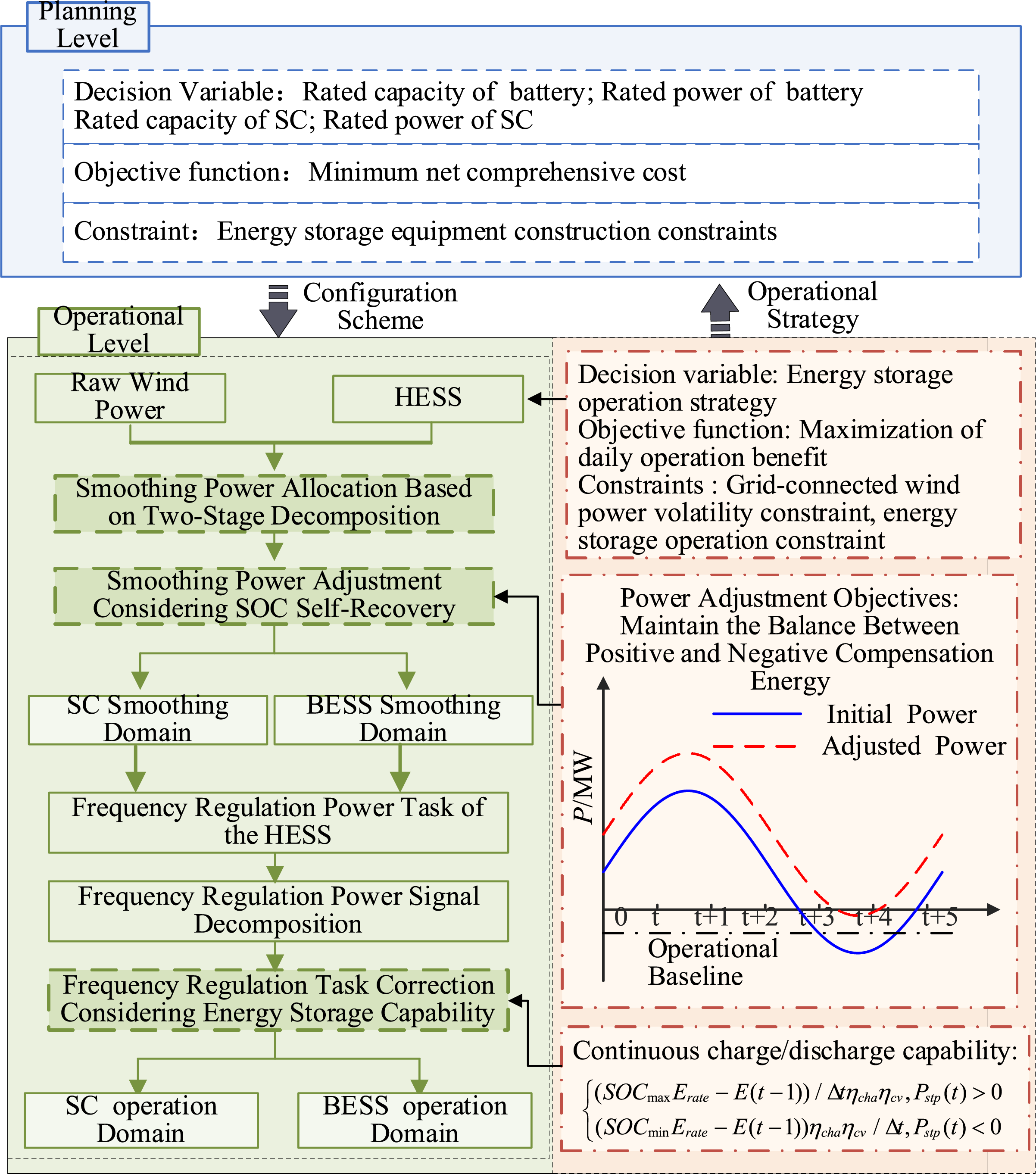
Figure 3: Hybrid energy storage operation-planning two-layer capacity allocation model
Thus, the formulation steps of the variable-baseline operational strategy for the HESS are as follows:
Step 1: The original wind power is decomposed using the improved complete ensemble empirical mode decomposition with adaptive noise (ICEEMDAN), yielding a set of intrinsic mode functions (IMFs) and a residual component. As shown in Eq. (7), the decomposed IMFs are reconstructed into low-frequency and high-frequency components. The low-frequency power signal that meets the grid-connection standards is taken as the grid-injected wind power
where
Step 2: Use the Black-winged kite algorithm (BKA)-VMD to allocate the total smoothing power between the battery and supercapacitor. The BKA optimizes the number of VMD decomposition layers K and the penalty coefficient
Step 3: Determine the smoothing baseline by resolving the imbalance between stored charge and discharge quantities.
Step 4: Based on Eq. (3), the primary frequency regulation power demand of the HESS
Step 5: Calculate the frequency regulation baseline according to the imbalance between positive and negative energy outputs.
Step 6: By superimposing the smoothing baseline and the frequency regulation baseline, the actual output
where
The adjusted operational power will maintain a balance between the charging and discharging energy, meeting the capacity sustainability constraint:
where
Based on the energy storage operation strategy detailed above, this paper develops a bi-level planning–operation model for hybrid energy storage systems, as shown in Fig. 3. The model consists of two layers. The planning layer determines the rated energy and power capacities of the battery and supercapacitor to minimize the annualized net life-cycle cost of the HESS. The operation layer optimizes the charge-discharge strategies for the battery and supercapacitor to maximize daily operational benefit. The planning objective function is defined as the difference between the annualized life-cycle cost of the HESS and the sum of accumulated daily operational benefits. The charge-discharge strategy in the operation layer is based on the capacity configuration results from the planning layer.
The objective function of the operation layer is to maximize the daily operational efficiency, which can be expressed as:
where
(1) The economic benefit
where
where
where
The carbon benefits of HESS on the wind power side include: the positive carbon benefit
where
The electricity purchase cost of the HESS from the main grid arises from implementing the variable-baseline operational strategy and can be calculated as follows:
where
(2) The penalty cost for unfulfilled operational tasks of the HESS consists of two components: wind curtailment penalty and power deficit penalty. The wind curtailment penalty refers to the economic loss caused by the inability of the storage system to absorb excess energy when the SOC has reached its upper limit. The power deficit penalty reflects the loss incurred when the storage system, having discharged down to its minimum SOC, fails to compensate for the remaining negative power demand.
where
(1) Capacity sustainability constraint: Within each operational day, the SOC of the energy storage system should achieve self-recovery, ensuring that the final SOC matches the initial SOC. This condition is essential for enabling the HESS to sustainably participate in wind power smoothing and frequency regulation over its entire life cycle.
where
(2) The SOC limitation constraint is
where
(3) The charge/discharge power constraint is
where
(4) The fluctuation constraint for grid-connected wind power is defined as:
where
In this paper, the fluctuation rate
where
3 Planning-Level Model for Optimal Economic Performance of HESS
The objective function, representing the goal of optimizing the economic performance of the HESS through capacity planning decisions, can be expressed as:
where
The life cycle cost of the HESS
where
where
The O&M cost is calculated as:
where
Given that the supercapacitor, as a power-type storage device, has a long cycle life, its replacement cost can be neglected over the 15-year life span of the HESS. However, the actual service life of the battery is closely related to factors such as the number of charge/discharge cycles and the depth of discharge (DOD) [20]. Therefore, the replacement cost of the battery must be considered, which can be calculated as follows:
where
The salvage value of the energy storage system can be calculated as follows:
where
Considering the installed capacity of the wind farm and the configuration cost of the energy storage equipment, the rated capacity of the energy storage equipment is subject to an upper limit. The construction constraint of energy storage equipment is:
where
This paper employs the adaptive genetic algorithm (AGA) to solve the optimization problem of the bi-level model. The core principle of AGA lies in dynamically adjusting its operational parameters based on the fitness of individuals, thereby achieving a balance between global and local search capabilities.
This study uses actual power data from a 100 MW wind farm in China, together with system frequency data. The dataset covers the period from 01 January to 31 January 2021, comprising 1-min sampled wind farm power data and 1-s sampled frequency data. Typical daily power and frequency profiles are extracted using the k-means clustering method. The typical-day wind power data are decomposed using ICEEMDAN, and the resulting intrinsic mode functions (IMF) are reconstructed into low-frequency and high-frequency components. The low-frequency component, meeting the grid-connection standard, is regarded as the grid-injected wind power, while the high-frequency component represents the smoothing power demand of the HESS. Simultaneously, the frequency regulation power demand of the HESS is calculated using Eq. (3).
As shown in Fig. 4, the orange curve represents the smoothing power demand of the HESS, while the blue curve denotes its primary frequency regulation power demand. The time resolutions of the smoothing and frequency regulation power demands are consistent with the sampling intervals of the original dataset, namely 1 min and 1 s, respectively. In this study, the BKA-VMD is applied to decompose the two power demand curves in Fig. 4, with the resulting high-frequency and low-frequency components serving as the reference power tasks for the supercapacitor and the battery, respectively. However, these reference power tasks exhibit an imbalance between positive and negative energy flows, preventing the SOC of the battery and supercapacitor from achieving self-recovery, as shown in Fig. 2. To address this issue, the two power demand curves are used as inputs to the operation-layer model, where an operational baseline is introduced as an optimization variable to adjust the reference power tasks, thereby enabling SOC self-recovery of the energy storage system.
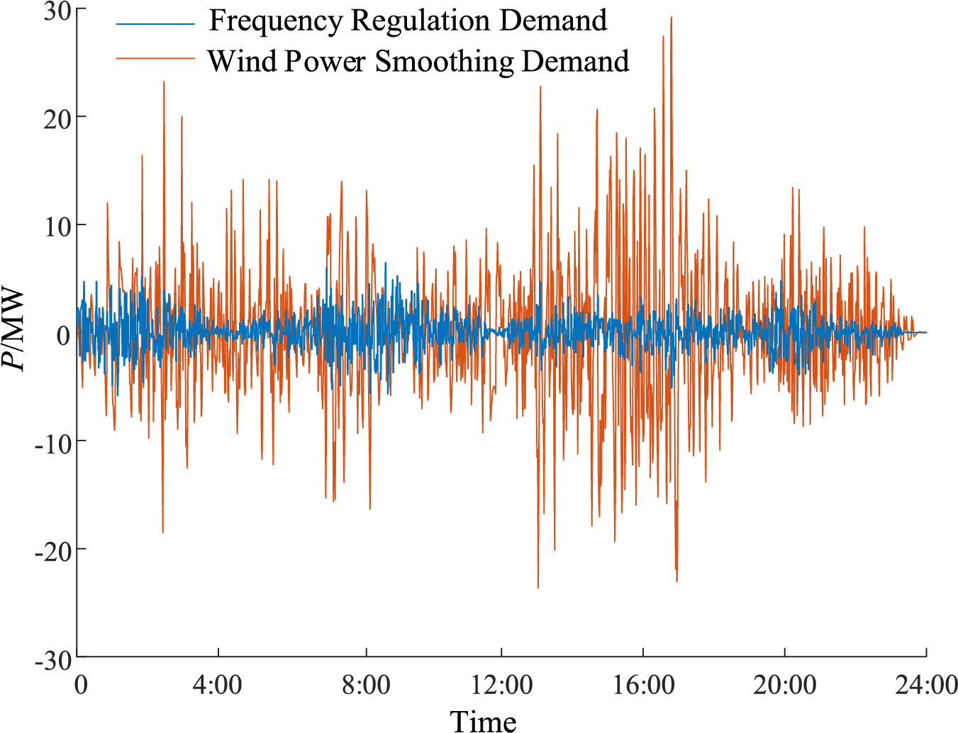
Figure 4: HESS smoothing and frequency regulation power tasks
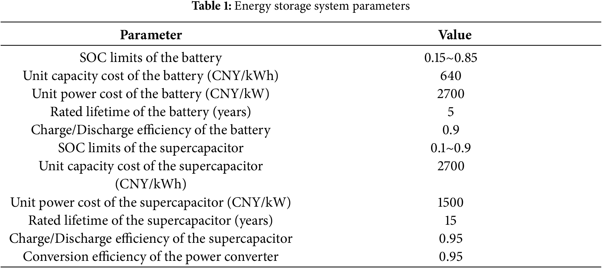
The parameters of the energy storage system used in this study are listed in Table 1 [22,23]. To verify the effectiveness of the proposed method, the following comparative scenarios are designed:
Scenario 1: SOC self-recovery is not considered; the HESS participates only in wind power smoothing.
Scenario 2: SOC self-recovery is not considered; the HESS participates in both wind power smoothing and frequency regulation.
Scenario 3: SOC self-recovery is considered; the HESS participates only in wind power smoothing.
Scenario 4: SOC self-recovery is considered; the HESS participates in both wind power smoothing and frequency regulation.
4.1 Analysis of HESS Operating States under Different Scenarios
Since the operational states of the energy storage in Scenario 1 and Scenario 2 are nearly the same when the self-recovery of SOC is not considered, and those in Scenario 3 and Scenario 4 are also similar, this paper compares the SOC of the battery and the supercapacitor under Scenario 2 and Scenario 4, as shown in Figs. 5 and 6. Under the dual-operation scenario involving both wind power smoothing and frequency regulation, as shown in Figs. 5 and 6, the proposed strategy ensures SOC self-recovery by maintaining energy balance, thereby enabling stable and sustainable control of the energy storage system.
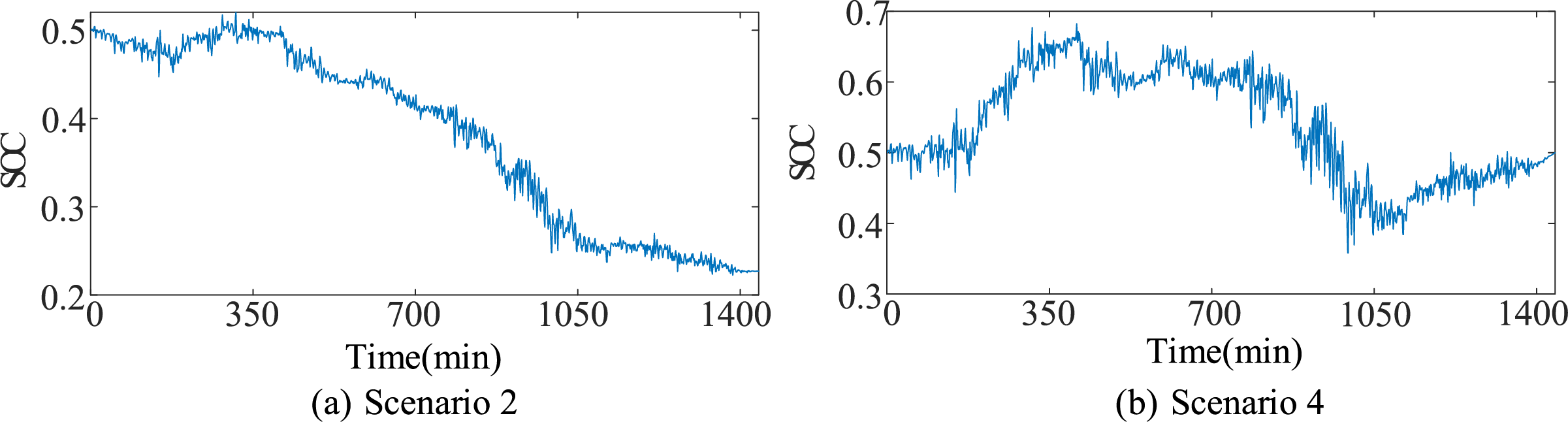
Figure 5: SOC of the supercapacitor under different scenarios
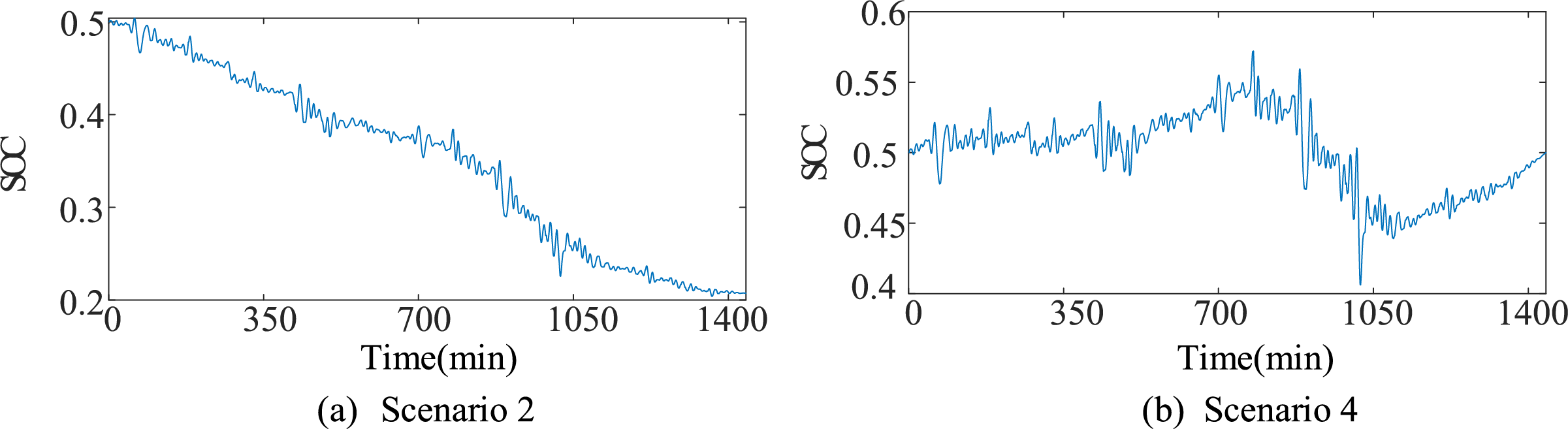
Figure 6: SOC of the battery under different scenarios
In Scenario 2, as shown in Figs. 5a and 6a, adopting a zero-baseline compensation strategy leads to an imbalance between positive energy absorption and negative energy compensation. As a result, both the supercapacitor and the battery fail to satisfy the capacity sustainability constraint. Considering the inefficiencies in charging/discharging and power conversion, the system tends to discharge more energy than it charges during long-term operation. This reduction limits the downward compensation capability of the HESS for the following operational day. Moreover, operating the battery at low SOC increases energy losses, shortens its lifespan, and raises replacement costs. To prevent SOC from falling below its lower bound, the system would require a higher rated capacity, further undermining economic efficiency.
Compared with Scenario 2, as shown in Figs. 5b and 6b, Scenario 4 applies the proposed variable-baseline strategy to modify the smoothing and frequency regulation power signals, thereby achieving a balance between charging and discharging. This ensures that the SOC remains consistent from the beginning to the end of the operational day, enhancing the operational reliability of the HESS. Meanwhile, the SOC is maintained within the range [0.4, 0.6]. Operating within this range helps maintain adequate charge–discharge margins for the energy storage system, enabling effective responses to wind power fluctuations and frequency deviations. In addition, this operating state prevents the battery from entering deep discharge zones, thereby mitigating its degradation [24].
4.2 Analysis of Wind Power Smoothing and Primary Frequency Regulation Performance
4.2.1 Analysis of Wind Power Smoothing Performance of HESS
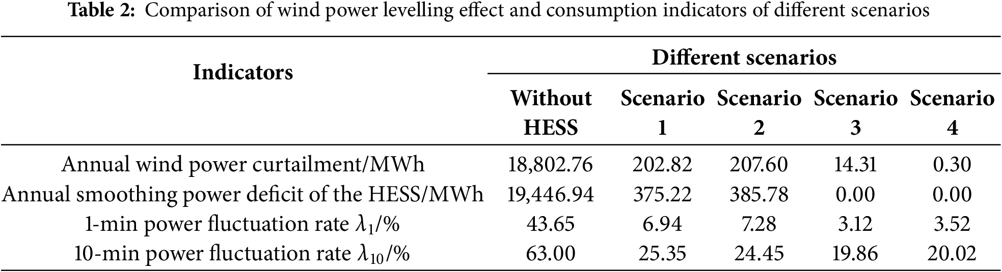
Table 2 presents the fluctuation rate and wind power utilization performance after smoothing. As shown in the table, compared with scenarios without energy storage, configuring HESS significantly reduces wind power curtailment. It ensures that the 1- and 10-min fluctuation rates of the smoothed wind power remain below the grid-connection limits of 10.0% and 33.3%, respectively. Moreover, compared with Scenarios 1 and 2, Scenarios 3 and 4 implement the proposed variable-baseline strategy. This strategy effectively reduces wind power curtailment and power deficits caused by the storage system reaching its SOC limits and thus being unable to further absorb or supply power as required.
4.2.2 Analysis of Primary Frequency Regulation Performance of HESS
Fig. 7 illustrates the primary frequency regulation performance of the HESS under Scenarios 2 and 4. As shown in Fig. 7, the upward frequency regulation capability of the HESS in Scenario 4 is markedly better than that in Scenario 2.
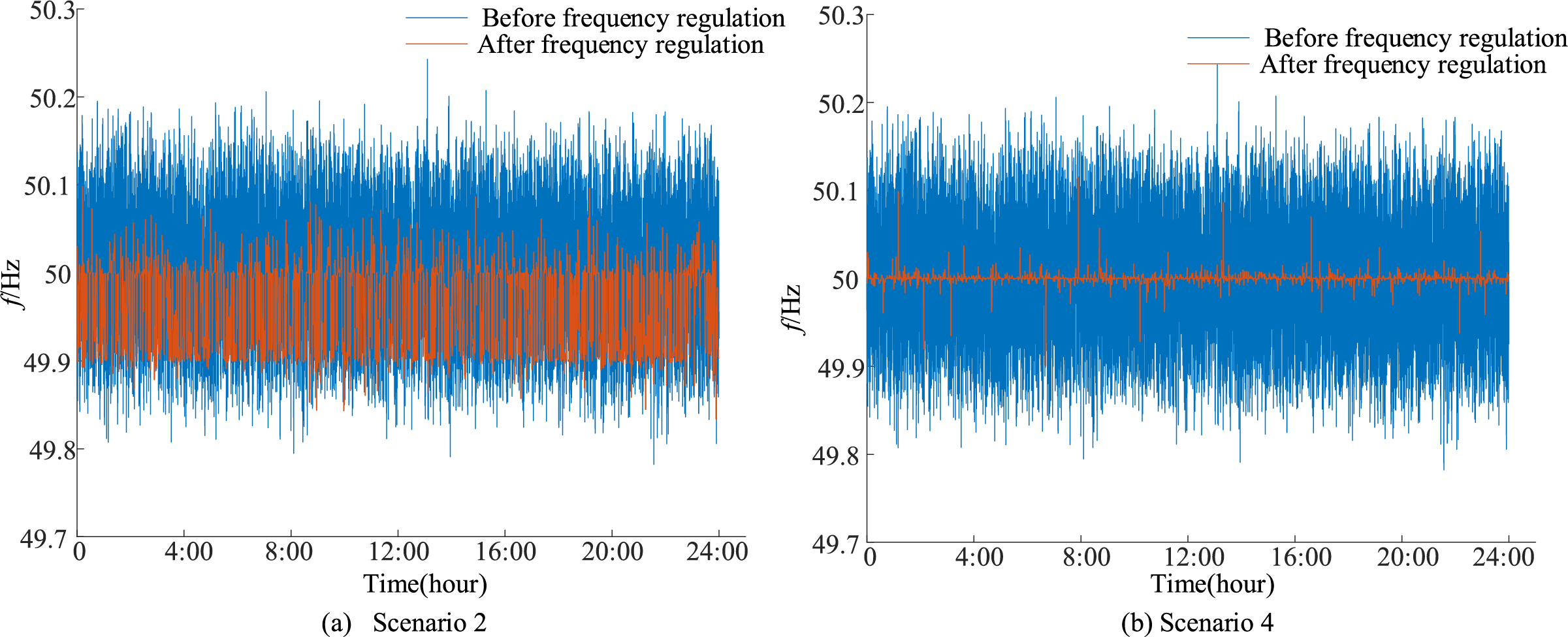
Figure 7: System frequency deviation curve under different scenarios
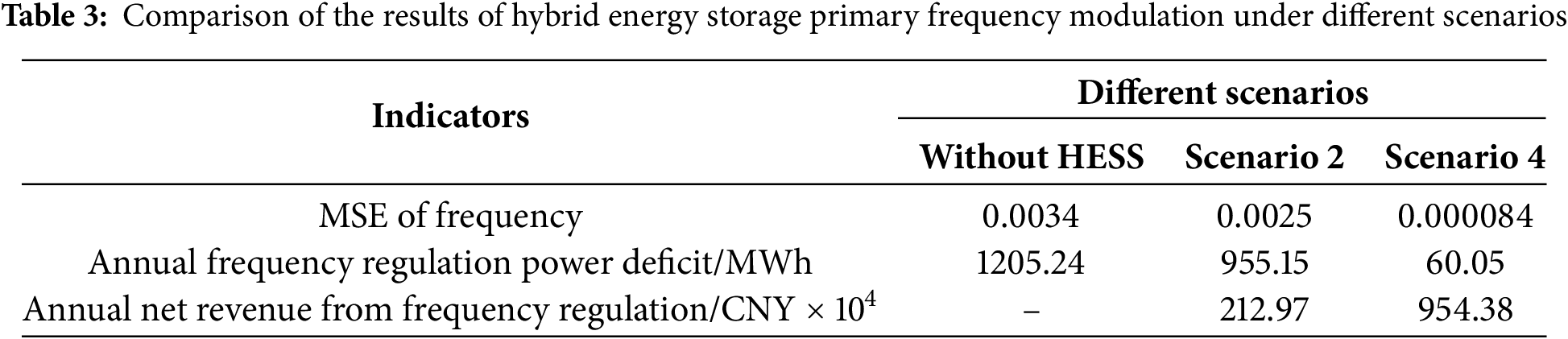
In this paper, the primary frequency regulation performance of the HESS under different scenarios is quantitatively evaluated using the mean square error (MSE) between the real-time system frequency and the rated system frequency. A smaller MSE indicates a smaller frequency deviation, which reflects better frequency regulation performance of the HESS.
where
Table 3 presents the performance and economic benefits of primary frequency regulation by the HESS under different scenarios. As shown in the table, the MSE of the raw frequency data is 0.0034, while Scenario 2 and Scenario 4 yield MSE values of 0.0025 and 0.000084, respectively. Scenario 4 demonstrates significantly enhanced frequency regulation performance compared to Scenario 2, attributable to the variable-baseline strategy. This strategy ensures sufficient active power reserves for both upward and downward regulation. In contrast, Scenario 2 (see Figs. 5a and 6a) results in the system operating primarily in a discharging state, diminishing its ability to respond to upward frequency regulation. Consequently, frequency regulation effectiveness and corresponding economic benefits are substantially lower than in Scenario 4.
4.3 HESS Capacity Configuration Results Analysis
4.3.1 Validation of the Bi-Level Capacity Configuration Model
Table 4 presents the capacity configuration results of the HESS under different scenarios. As shown in Table 4, Scenarios 3 and 4, which incorporate SOC self-recovery, exhibit better economic performance compared to Scenarios 1 and 2, which do not.
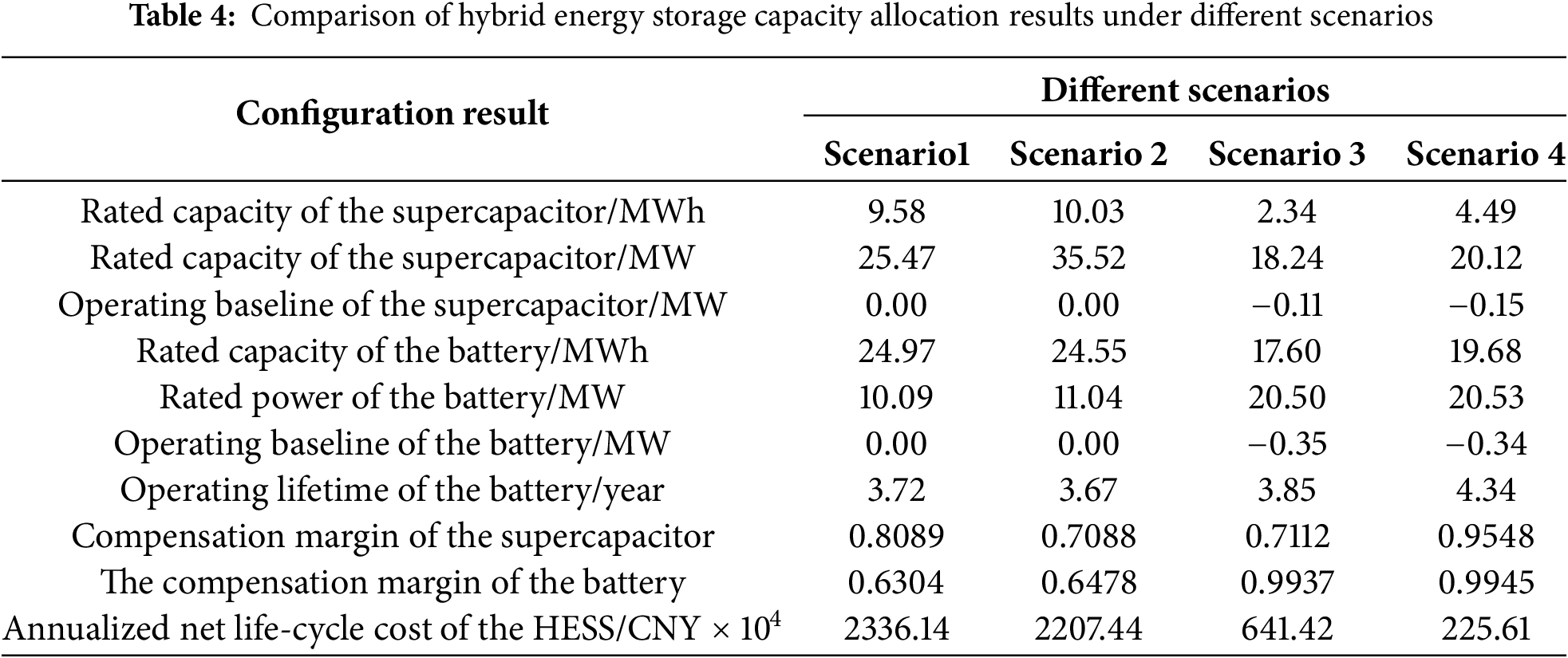
The underlying reasons for the improved economic performance in Scenarios 3 and 4 are as follows: First, in Scenarios 1 and 2, the battery remains discharging with SOC below 0.5 for a significant portion of the time—33.31% and 49.72%, respectively—whereas this proportion drops to only 15.63% and 14.31% in Scenarios 3 and 4. Prolonged operation under deep discharge conditions shortens battery lifespan and increases replacement costs. Second, the negative compensation energy greatly exceeds the positive absorption energy. To prevent the SOC from falling below its lower bound, Scenarios 1 and 2 require larger storage capacities. In addition, as evidenced by Tables 2 and 3, neglecting SOC self-recovery limits the energy throughput capability of the HESS, reduces its economic benefits
Compared with Scenario 3, Scenario 4 requires a higher rated power and energy capacity for the HESS, as it handles both smoothing and frequency regulation, leading to an increase in configuration costs. However, the substantial revenue from frequency regulation offsets this cost, leading to a 64.83% reduction in the annualized net life-cycle cost of the HESS. This shows that combined smoothing and frequency regulation offer greater economic benefits than single-function use.
To evaluate the ability of the battery and the supercapacitor to participate in active power regulation under different scenarios, this paper introduces a “charge–discharge saturation capability function” to characterize the relationship between the SOC and the charge–discharge margin of the energy storage system [25].
where
As shown in Table 4, the proposed variable-baseline control strategy enables the HESS to achieve higher compensation margins even with smaller configured capacities. By maintaining a balance between positive and negative energy flows, the SOC of the storage devices remains within a reasonable operating range. This enhances the HESS’s flexibility and regulation capability under the dual requirements of wind power smoothing and primary frequency regulation.
4.3.2 Validation of the Economic Advantage of HESS
To verify the advantages of HESS over single-type storage under the same scenario, different energy storage configurations are designed based on Scenario 4. The corresponding capacity configuration results are presented in Table 5.
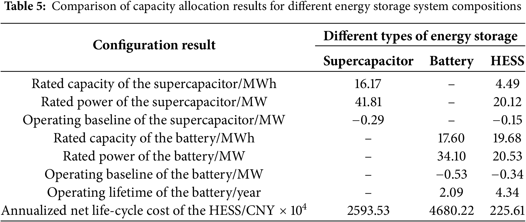
As shown in Table 5, under the dual requirements of wind power smoothing and frequency regulation, the annualized net life-cycle cost of single-type energy storage systems is markedly higher than that of the hybrid configuration. Among them, the battery-only configuration exhibits the poorest economic performance. This is primarily because, in the absence of a supercapacitor to handle high-frequency components of the power tasks, the battery incurs greater operational losses and requires replacement seven times over a 15-year life cycle—compared with only three replacements in the HESS.
4.4.1 Unit Capacity Cost of Energy Storage
The unit capacity cost of energy storage directly influences the calculation of the annualized life-cycle cost of the HESS. Currently, the unit capacity costs of batteries and supercapacitors remain relatively high, especially for supercapacitors, which is one of the main reasons why the total revenue of the HESS is less than its total cost. With advancements in energy storage technologies, the unit costs of batteries and supercapacitors are expected to decline gradually. Fig. 8 shows the rated capacities of the battery and supercapacitor, the annualized life-cycle cost, and the annualized net benefit under different unit capacity costs. As shown in Fig. 8, a reduction in unit capacity cost leads to a decrease in the annualized life-cycle cost of the HESS. When the unit capacity cost is reduced by 15%, the revenue of the HESS exceeds its cost. Moreover, as depicted in Fig. 8, the rated capacity of the supercapacitor increases gradually as the unit capacity cost decreases, while the change in the rated capacity of the battery is relatively minor. This is because the unit capacity cost of supercapacitors is significantly higher than that of batteries, making the capacity configuration of supercapacitors more sensitive to changes in unit capacity cost.
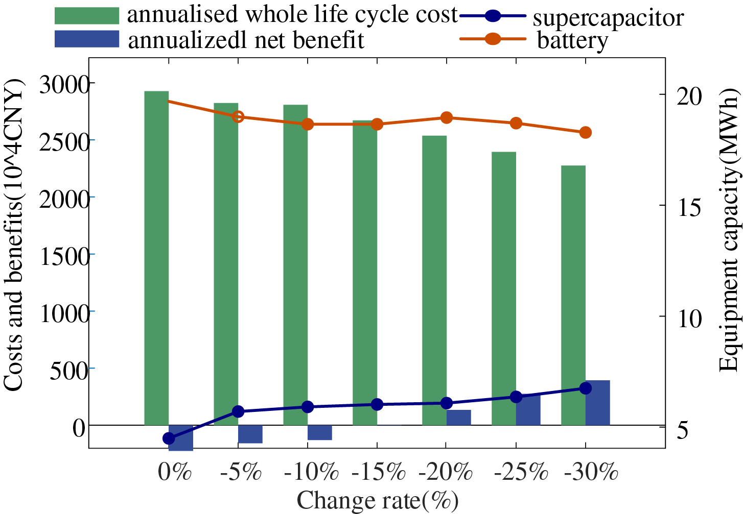
Figure 8: Capacity configuration results for different unit capacity costs
4.4.2 Primary Frequency Regulation Revenue Coefficient
The revenue coefficient of primary frequency regulation is closely related to the economic benefits of the HESS. By gradually increasing the revenue coefficient for HESS participation in primary frequency regulation by 5% to 30%, the corresponding capacity configuration results and economic indicators of the HESS under different incentive levels are shown in Fig. 9. As illustrated in Fig. 9, an increase in the revenue coefficient progressively enhances the economic performance of the HESS. When the coefficient increases by 25%, the revenue of the HESS surpasses its cost. In contrast, the rated capacities of the battery and supercapacitor exhibit limited sensitivity to changes in the primary frequency regulation revenue coefficient.
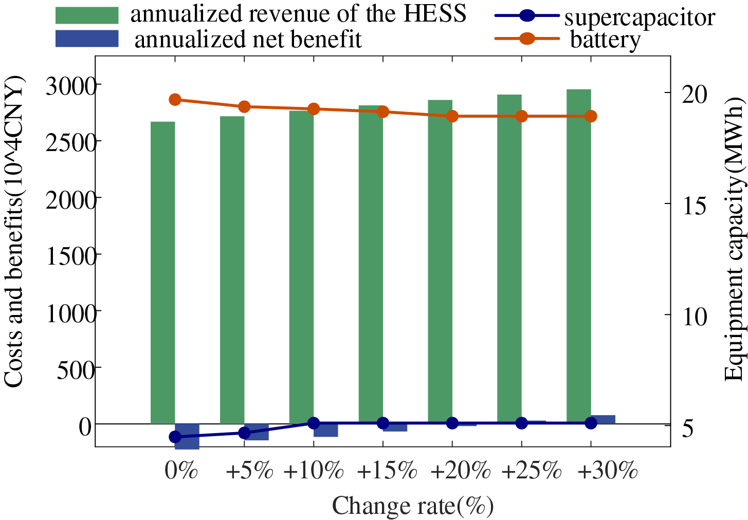
Figure 9: Capacity configuration results with different primary frequency regulation gain factors
To address the dual requirements of wind power smoothing and primary frequency regulation, and to achieve SOC self-recovery control for both the battery and supercapacitor, this paper proposes a bi-level planning–operation capacity configuration model that considers the balance between positive and negative energy dispatches in storage operation. The case study results demonstrate the following:
(1) The HESS capacity configuration result obtained from the proposed optimization model effectively smooths wind power output fluctuations and reduces system frequency deviations, thereby improving the wind farm’s active power support capability for the power system.
(2) By applying the proposed variable-baseline control strategy, SOC self-recovery for energy storage is achieved, thereby enhancing the compensation capability of the HESS when facing the dual demands of wind power smoothing and frequency regulation.
(3) Regarding the economic configuration of HESS under the dual requirements, the proposed method reduces the total capacity demand and extend battery lifespan, thereby lowering the life cycle cost. Meanwhile, it improves the fulfillment rate of smoothing and frequency regulation tasks, increases the economic benefits of deploying HESS, and reduces the penalty costs from operational power deficits, thereby achieving an economically efficient capacity configuration.
Acknowledgement: The authors wish to express their appreciation to Nanjing Institute of Technology for their instrumental support and resources during this research.
Funding Statement: This work was supported by Graduate Research and Innovation Program Project of Nanjing Institute of Technology (No. TB202517022).
Author Contributions: The authors confirm contribution to the paper as follows: Conceptualization, Fan Chen, Tianhui Zhang, Qiang Zhang and Man Wang; methodology, Fan Chen and Tianhui Zhang; validation, Tianhui Zhang; formal analysis, Fan Chen; investigation, Fan Chen; resources, Fan Chen and Qiang Zhang; writing—original draft preparation, Tianhui Zhang; writing—review and editing, Fan Chen, Man Wang, Zhiheng Zhuang and Zihan Ma; visualization, Tianhui Zhang; supervision, Fan Chen; project administration, Fan Chen; funding acquisition, Fan Chen. All authors reviewed the results and approved the final version of the manuscript.
Availability of Data and Materials: Data available on request from the authors.
Ethics Approval: Not applicable.
Conflicts of Interest: The authors declare no conflicts of interest to report regarding the present study.
Glossary
| The proportional coefficients of the operation and maintenance cost relative to the investment cost for the battery | |
| The unit feed-in tariff of the wind farm | |
| The proportional coefficients of the operation and maintenance cost relative to the investment cost for the supercapacitor | |
| BKA | Black-winged kite algorithm |
| The initial investment cost of energy storage equipment | |
| The operation and maintenance cost of the energy storage system | |
| The replacement cost of the energy storage system | |
| The salvage value of the energy storage system | |
| The life cycle cost of the hybrid energy storage system | |
| The electricity purchase cost of the hybrid energy storage system | |
| The coefficient of the cost of purchasing electricity | |
| DOD | Depth of discharge |
| The actual depth of discharge of the battery at time t | |
| Rated depth of discharge | |
| The rated capacity of the battery or supercapacitor (MWh) | |
| Energy capacity of the storage device at time t − 1 (MWh) | |
| Rated capacity of the battery | |
| Rated capacity of the supercapacitor | |
| The amount of electricity of the battery participating in primary frequency regulation | |
| The amount of electricity of the supercapacitor participating in primary frequency regulation | |
| The amount of abandoned electricity reduced by the configuration of the hybrid energy storage system. | |
| The wind curtailment energy | |
| The smoothing deficit energy | |
| The frequency regulation energy deficit | |
| Rated frequency of the power system (Hz) | |
| Actual frequency at time t (Hz) | |
| Annualized net life-cycle cost of the hybrid energy storage system | |
| The mean square error of the power system’s frequency | |
| HESS | Hybrid energy storage system |
| The penalty coefficients for wind curtailment | |
| The penalty coefficients for the smoothing power deficit | |
| The penalty coefficients for frequency regulation power deficit | |
| The penalty cost for unfulfilled operational tasks | |
| K | The number of variational mode decomposition layers |
| The marginal emission factor of electricity | |
| The conversion factor from frequency regulation power to thermal unit output | |
| The carbon emission factor generated by the investment and construction of the hybrid energy storage system | |
| MSE | Mean square error |
| The number of battery replacements within the whole life cycle of the hybrid energy storage system | |
| Rated power of the battery | |
| Rated power of the supercapacitor | |
| The actual primary frequency modulation output of energy storage at time t (MW) | |
| The rated power of the battery and the supercapacitor (MW) | |
| The available charging or discharging power of the energy storage system at time t after completing the smoothing task (MW) | |
| Grid-connected power of the wind farm at time t (MW) | |
| The required primary frequency regulation power at time t (MW) | |
| The positive absorption power of the energy storage system at time t (MW) | |
| The negative compensation power of the energy storage system at time t (MW) | |
| The smoothing power task of the hybrid energy storage system at time t | |
| The smoothing power task of the battery at time t | |
| The smoothing power task of the supercapacitor at time t | |
| Discharging power of the battery (MW) | |
| Modulation coefficient | |
| The number of cycles under the rated depth of discharge | |
| The number of cycles under the actual depth of discharge | |
| Life equivalence conversion coefficient of the battery | |
| The unit gain coefficient of the hybrid energy storage system participating in primary frequency regulation | |
| The benefit of the hybrid energy storage system’s participation in primary frequency regulation | |
| The benefit of reduced wind abandonment | |
| The carbon emission benefit | |
| The positive carbon benefit from reducing wind abandonment and participating in primary frequency regulation | |
| The negative carbon benefit from investment in the construction, operation and maintenance of the hybrid energy storage system | |
| The unit price of carbon trading | |
| SOC | State of charge |
| The lower limit of the state of charge of the energy storage system | |
| The upper limit of the state of charge of the energy storage system | |
| The actual state of charge of the battery at time t | |
| The state of charge of the supercapacitor at the time | |
| The SOC after the end of the operation cycle | |
| The initial SOC of the energy storage | |
| The whole life cycle of the hybrid energy storage system | |
| VMD | Variational mode decomposition |
| Actual service life of the battery (year) | |
| Variational mode decomposition penalty coefficient | |
| Fitting coefficient | |
| The salvage value rate | |
| The discount rate | |
| The carbon emission allowance per unit of electricity | |
| The charging efficiency of the energy storage system | |
| The charging efficiency of the energy storage system | |
| The conversion efficiency of the energy storage converter | |
| The unit power investment costs of the battery | |
| The unit power investment costs of the supercapacitor | |
| The unit energy capacity configuration costs of the battery | |
| The unit energy capacity configuration costs of the supercapacitor | |
| The 1-min fluctuation of the actual grid-connected power | |
| The 10-min fluctuation of the actual grid-connected power | |
| The 1-min maximum fluctuation in compliance with the grid-connected wind power standard | |
| The 10-min maximum fluctuation in compliance with the grid-connected wind power standard | |
| The average compensation margin of the energy storage system over the operational day | |
| The compensation margin corresponding to a given state of charge |
References
1. Huang J, Xu Y. Multi-timescale coordinated control of wind power plant for supporting power system operation. IEEE Trans Power Syst. 2024;40(1):355–67. doi:10.1109/TPWRS.2024.3387537. [Google Scholar] [CrossRef]
2. Engels J, Claessens B, Deconinck G. Optimal combination of frequency control and peak shaving with battery storage systems. IEEE Trans Smart Grid. 2020;11(4):3270–9. doi:10.1109/TSG.2019.2963098. [Google Scholar] [CrossRef]
3. Zhang L, Zhang T, Zhang K, Hu W. Research on power fluctuation strategy of hybrid energy storage to suppress wind-photovoltaic hybrid power system. Energy Rep. 2023;10(11):3166–73. doi:10.1016/j.egyr.2023.09.176. [Google Scholar] [CrossRef]
4. Zhang X, Kang L, Wang X, Liu Y, Huang S. Capacity optimization configuration of hybrid energy storage systems for wind farms based on improved k-means and two-stage decomposition. Energies. 2025;18(4):795. doi:10.3390/en18040795. [Google Scholar] [CrossRef]
5. Shen J, Huang S, Liu C, Li S, Wu J. Optimal configuration method of wind farm hybrid energy storage based on EEMD-EMD and grey relational degree analysis. Front Energy Res. 2023;10:1021189. doi:10.3389/fenrg.2022.1021189. [Google Scholar] [CrossRef]
6. Hou E, Xu Y, Tang J, Wang Z. Strategy of flywheel-battery hybrid energy storage based on optimized variational mode decomposition for wind power suppression. Electronics. 2024;13(7):1362. doi:10.3390/electronics13071362. [Google Scholar] [CrossRef]
7. Xing C, Xi X, Li S. A rolling optimization method of reserve capacity considering wind power frequency control. J Renew Sustain Energy. 2022;14(1):013301. doi:10.1063/5.0059888. [Google Scholar] [CrossRef]
8. Chen C, Tang W, Xia Y, Chen C. Hybrid-energy storage optimization based on successive variational mode decomposition and wind power frequency modulation power fluctuation. Energies. 2024;17(17):4391. doi:10.3390/en17174391. [Google Scholar] [CrossRef]
9. Hong F, Wei K, Ji W, Hao J, Fang F, Liu J. A cross-entropy-based synergy method for capacity configuration and SOC management of flywheel energy storage in primary frequency regulation. Energy. 2025;316(9):134498. doi:10.1016/j.energy.2025.134498. [Google Scholar] [CrossRef]
10. Chen C, Wang Y, Zhou K, Huang L. Frequency regulation optimization for wind storage based on frequency regulation reliability and state of charge in isolated island off-grid. Energy Sci Eng. 2023;11(1):192–205. doi:10.1002/ese3.1322. [Google Scholar] [CrossRef]
11. Duanmu C, Shi L, Jian D, Ding R, Li Y, Wu F. Optimized battery capacity allocation method for wind farms with dual operating conditions. Sustainability. 2024;16(9):3615. doi:10.3390/su16093615. [Google Scholar] [CrossRef]
12. Zhu J, Pan W, Gu J. Research on hybrid energy storage configuration in grid wind power scheduling tracking under statistics and frequency decomposition. J Electrochem Energy Convers Storage. 2021;18(3):031006. doi:10.1115/1.4048659. [Google Scholar] [CrossRef]
13. Wang J, Wang X, Chen H, Gao Y, Chen H, Liu W. Capacity configuration of a hybrid energy storage system for the fluctuation mitigation and frequency regulation of wind power based on Aquila Optimizer and Variational Mode Decomposition. Energy. 2025;330(7):136894. doi:10.1016/j.energy.2025.136894. [Google Scholar] [CrossRef]
14. Liu H, Ji X, Kang J, Wang W. Coordinated control strategy of wind power fluctuation suppression and frequency modulation based on hybrid energy storage system. In: 2021 IEEE 4th International Electrical and Energy Conference (CIEEC); 2021 May 28; Wuhan, China. [Google Scholar]
15. Lu Q, Yang Y, Chen J, Liu Y, Liu N, Cao F. Capacity optimization of hybrid energy storage systems for offshore wind power volatility smoothing. Energy Rep. 2023;9(7):575–83. doi:10.1016/j.egyr.2023.04.172. [Google Scholar] [CrossRef]
16. Zhu S, Lu J, Li Z, Lin J. Evaluation method for the firm power escalation of a wind-storage hybrid power system. Energies. 2017;10(10):1539. doi:10.3390/en10101539. [Google Scholar] [CrossRef]
17. Li C, Wang X, Li J, Zhu X, Yan G, Jia C. Multi-constrained optimal control of energy storage combined thermal power participating in frequency regulation based on life model of energy storage. J Energy Storage. 2023;73(5):109050. doi:10.1016/j.est.2023.109050. [Google Scholar] [CrossRef]
18. Zhu W, Xu X, Ding B, Zhang Z, Gao Q. Cooperative game-based energy storage planning for wind power cluster aggregation station. Energy Rep. 2024;11(3):4021–31. doi:10.1016/j.egyr.2024.03.056. [Google Scholar] [CrossRef]
19. Wen S, Gong Y, Mu X, Zhao S, Wang C. Optimal configuration of flywheel-battery hybrid energy storage system for smoothing wind-solar power generating fluctuation. Energies. 2025;18(8):2055. doi:10.3390/en18082055. [Google Scholar] [CrossRef]
20. Cui J, Tan Q, Liu L, Li J. Environmental benefit assessment of second-life use of electric vehicle lithium-ion batteries in multiple scenarios considering performance degradation and economic value. Environ Sci Technol. 2023;57(23):8559–67. doi:10.1021/acs.est.3c00506. [Google Scholar] [PubMed] [CrossRef]
21. Zheng T, Ye M, Wu Q. Capacity allocation method for a hybrid energy storage system participating in secondary frequency regulation based on variational mode decomposition. Int J Elect Pow Energy Syst. 2025;167(4):110631. doi:10.1016/j.ijepes.2025.110631. [Google Scholar] [CrossRef]
22. Liu X, Xie L, Ma L, Ye J, Bian Y, Cui C. Hybrid energy storage two-layer smoothing control model considering maximum benefit of wind power. Acta Energiae Solaris Sin. 2024;45(12):596–605. (In Chinese). doi:10.19912/j.0254-0096.tynxb.2023-1157. [Google Scholar] [CrossRef]
23. Chen Y, Jia P, Meng G, Yao W, Tiantian L. Optimal capacity configuration of hybrid energy storage system considering smoothing wind power fluctuations and economy. IEEE Access. 2022;10:101229–36. doi:10.1109/access.2022.3205021. [Google Scholar] [CrossRef]
24. Yi T, Ye H, Li Q, Zhang C, Ren W, Tao Z. Energy storage capacity optimization of wind-energy storage hybrid power plant based on dynamic control strategy. J Energy Storage. 2022;55:105372. doi:10.1016/j.est.2022.105372. [Google Scholar] [CrossRef]
25. Lin L, Cao Y, Kong X, Li Y, Jia Y, Zhang Z. Hybrid energy storage system control and capacity allocation considering battery state of charge self-recovery and capacity attenuation in wind farm. J Energy Storage. 2024;75(4):109693. doi:10.1016/j.est.2023.109693. [Google Scholar] [CrossRef]
Cite This Article
 Copyright © 2025 The Author(s). Published by Tech Science Press.
This work is licensed under a Creative Commons Attribution 4.0 International License , which permits unrestricted use, distribution, and reproduction in any medium, provided the original work is properly cited.
 Downloads
 Citation Tools