
 Submit a Paper
 Propose a Special lssue
 Open Access
ARTICLE

Research on Bottomhole Pressure Control Method Based on Backpressure Regulation in Deepwater Dual-Layer Pipe Dual-Gradient Drilling
1 Gathering and Transportation Engineering Technology Research Institute, Southwest Oil and Gas Field Company, Chengdu, 610041, China
2 National Key Laboratory of Oil and Gas Reservoir Geology and Exploitation, Southwest Petroleum University, Chengdu, 610500, China
3 China National Offshore Oil Corporation (China) Limited Zhanjiang Branch, Zhanjiang, 524057, China
* Corresponding Author: Zheng Zhang. Email:
Energy Engineering 2025, 122(11), 4679-4702. https://doi.org/10.32604/ee.2025.068371
Received 27 May 2025; Accepted 05 August 2025; Issue published 27 October 2025
 View Full Text
 Download PDF
Abstract
With the growing demand for offshore energy, deepwater drilling has become a vital technology in petroleum engineering. However, conventional drilling systems often face limitations such as delayed bottomhole pressure response and low control precision, particularly under narrow pressure window and complex formation conditions. To address these challenges, Dual-layer Pipe dual-gradient drilling (DGD) technology has been introduced, utilizing a dual-pipe structure and downhole lift pumps to extend the pressure control range. Despite these advantages, current DGD systems lack fast and precise bottomhole pressure control due to their reliance on indirect flow-based methods. This study proposes a bottomhole pressure control method based on backpressure regulation using a hybrid fuzzy-PID control strategy. A dynamic pressure calculation model is developed for the Dual-layer Pipe DGD system, incorporating coupling among choke valve opening, surface backpressure, and bottomhole pressure. The fuzzy-PID controller adjusts valve operation in real-time based on pressure deviation and its rate of change, improving response speed and control accuracy. Simulink-based simulations demonstrate that the proposed system achieves rapid pressure regulation with an overshoot below 5% and steady-state error under 0.12%. Compared to conventional PID control, the fuzzy-PID system shows superior adaptability to pressure variations. This research enhances the theoretical foundation of backpressure control in deepwater DGD operations and provides a practical approach for improving safety and efficiency in complex drilling environments.Keywords
As onshore oil and gas resources gradually deplete, the exploration and development of offshore resources continue to accelerate, making deepwater drilling a pivotal direction in petroleum engineering [1–4]. However, deepwater drilling faces unique challenges, including complex subsea formation pressure gradients, narrow density windows, and limitations in downhole equipment strength and wellhead pressure capacity, which hinder the safety and efficiency of traditional drilling techniques [5]. To overcome these challenges, deepwater Dual-layer Pipe dual-gradient drilling (DGD) technology has emerged. By incorporating Dual-layer Pipe structures and downhole lift pumps, this technology breaks through the limitations of conventional subsea pump arrangements, broadens the bottomhole pressure regulation range, and enhances operational safety and flexibility, thereby becoming a focal area in deepwater drilling research and application [6,7]. However, current systems primarily rely on drilling fluid flow rate adjustments for bottomhole pressure control, lacking an independent and precise backpressure regulation mechanism. As a result, response delays and inadequate precision frequently occur in the face of complex formation variations and sudden operational changes, thereby restricting its applicability in high-risk environments. Therefore, there is an urgent need to develop a backpressure regulation method tailored to deepwater Dual-layer Pipe DGD, establishing a refined bottomhole pressure control mechanism to advance its theoretical framework and promote safe, efficient deployment in deepwater drilling.
In recent years, extensive research on backpressure regulation and control methods has significantly advanced its application in complex drilling environments. Early efforts by international oil companies such as Shell and Chevron [8] deployed surface choke systems in deepwater regions, regulating wellhead choke valve openings to apply backpressure for basic bottomhole pressure control, laying a practical foundation for subsequent studies. Vieira et al. [9] introduced a constant bottomhole pressure control mode, applying real-time feedback for closed-loop control, which markedly improved regulation accuracy and system stability. Totland [10] incorporated PID control algorithms into choke systems, enhancing response speed and robustness through proportional, integral, and derivative strategies. To address nonlinear downhole challenges, Kaasa et al. [11] developed a simplified hydraulic model to enable intelligent estimation of downhole pressure, which laid the foundation for control strategies in managed pressure drilling. Kokkinis et al. [12] further provided a comprehensive review of automated operations in drilling and mining, offering insights into system coordination, task automation, and intelligent decision-making. With advancements in intelligent technologies, Li et al. [13] combined neural networks with fuzzy-PID control to enhance self-learning and parameter adjustment in nonlinear environments. Li et al. [14] developed a deep neural network-based backpressure regulation system, achieving stability and precision through real-time data-driven optimization.
In addition, several studies have focused specifically on bottomhole pressure control strategies tailored to deepwater dual-gradient drilling. Zhou and Nygaard [15] pioneered a control algorithm that automatically adjusts drilling pump displacement in response to bottomhole pressure deviations, thereby modulating the lift pump head and controlling wellbore pressure. Hauge et al. [16] proposed a real-time flow regulation method based on a wellbore pressure control model, using variations in spacer fluid level to accurately manage bottomhole pressure. Nazir et al. [17] established a time-dependent hydraulic model for individual flow segments in the wellbore, enabling fine-tuned pressure control under dynamic drilling conditions. Wang et al. [18] introduced a dynamic bottomhole pressure regulation method under deepwater DGD scenarios, constructing an optimization model constrained by flow parameters to minimize pressure fluctuations within the narrow pressure window. Zhang et al. [19] analyzed the relationship between flow rate and bottomhole pressure under the Riserless Mud Recovery (RMR) system and developed governing equations for pressure control in steady-state conditions. Pei et al. [20] conducted innovative experiments using subsea pump regulation during DGD, demonstrating that controlled variation in surface pump flow rate effectively modulates lift pump head and stabilizes wellbore pressure. Most existing approaches rely heavily on adjusting drilling fluid flow rates or modulating lift pump displacement, which suffer from delayed system response due to the inherent inertia of fluid transport in long annular spaces and the limited control authority of surface equipment. Moreover, the coupling between choke valve opening, surface backpressure, and downhole pressure is often nonlinear and time-variant, making traditional PID control methods less effective under rapidly changing operational conditions. Additionally, the lack of real-time feedback from deepwater environments exacerbates response lag and degrades control precision, particularly in narrow pressure window formations.
This study establishes a mathematical model for bottomhole pressure regulation in deepwater Dual-layer Pipe DGD by analyzing the coupling relationships among choke valve opening, surface backpressure, and bottomhole pressure. A fuzzy control theory is introduced to dynamically adjust PID controller parameters via fuzzy logic rules, regulating choke valve openings to generate precise backpressure. A multi-scenario Simulink simulation validates the system’s adaptability and stability under complex drilling conditions. This research enriches the theoretical system of bottomhole pressure regulation in deepwater Dual-layer Pipe DGD, facilitating its safe and efficient application.
2 Drilling Principles and Bottomhole Pressure Calculation Model
2.1 Deepwater Dual-Layer Pipe Dual-Gradient Drilling System
The deepwater Dual-layer Pipe dual-gradient drilling system integrates key components such as dual pipes, a top-drive adapter, and downhole hydraulic lift pumps, establishing a novel tri-channel pressure control mechanism that encompasses the inner pipe, outer pipe, and outer annulus (Fig. 1). The drilling fluid is injected into the bottomhole through the outer pipe of the Dual-layer Pipe system. Driven by the turbine motor of the lift pump, the cuttings-laden fluid is then returned to the surface manifold via the inner pipe, forming a reverse circulation flow pattern. During this process, the pressure differential established between the suction inlet and discharge outlet of the lift pump significantly reduces the bottomhole pressure. Meanwhile, a three-segment fluid structure is created in the outer annulus through density differential design. Owing to the tri-channel characteristics of the Dual-layer Pipe system, the outer annulus is entirely filled with fluid. The upper section of the annulus contains lower-density seawater, while the lower section consists of higher-density drilling fluid, with the two separated by a spacer fluid. This configuration establishes two distinct pressure gradients—one across the seawater segment and another across the drilling fluid segment—above and below the spacer fluid. Furthermore, the inner pipe, outer pipe, and outer annulus of the Dual-layer Pipe system collectively form a tri-channel structure. This unique arrangement creates an equivalent pressure system at the bottomhole, integrating the inner pipe, outer pipe, and outer annulus. As a result, the bottomhole pressure maintains dynamic equilibrium. When the bottomhole pressure fluctuates, the spacer fluid level adjusts vertically—rising or falling in response to pressure increases or decreases—thereby enabling dynamic regulation of the bottomhole pressure.
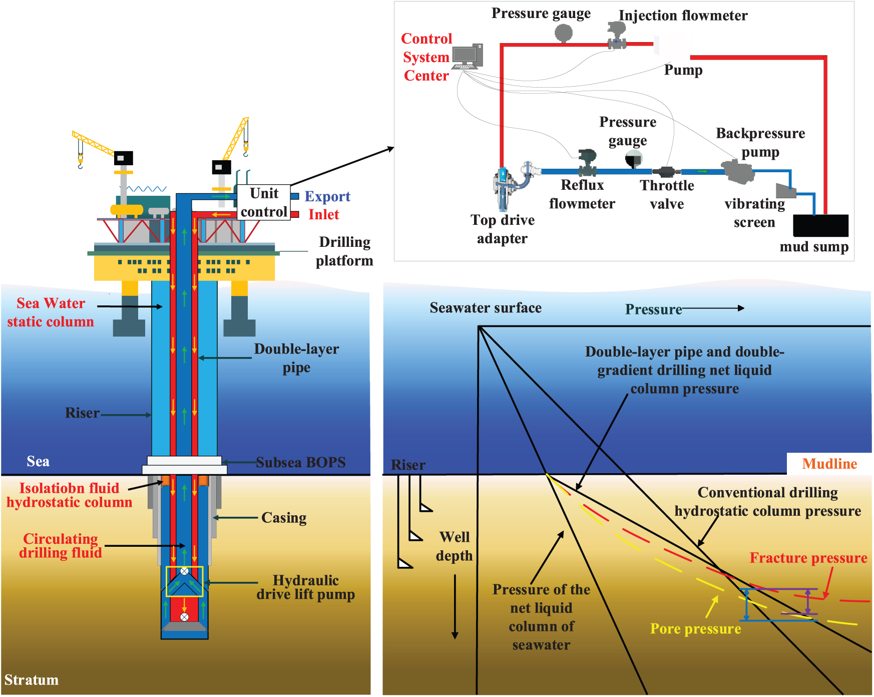
Figure 1: Schematic diagram of deepwater Dual-layer Pipe dual-gradient drilling
2.2 Bottomhole Pressure Calculation Model
During deepwater Dual-layer Pipe dual-gradient drilling (DGD) operations, the spacer fluid level in the outer annulus varies with increasing well depth. At any given target depth point, changes in the spacer fluid level height within the outer annulus will induce corresponding variations in wellbore pressure at that location, creating dynamic pressure fluctuations—a phenomenon absent in conventional drilling systems. To address this, a bottomhole pressure calculation model must be established based on the distribution patterns of spacer fluid levels in the outer annulus under different drilling depth conditions in Dual-layer Pipe dual-gradient drilling systems. The continuous partial differential equations (PDEs) describing drilling fluid flow in the wellbore are given by [21,22]:
The finite volume method is employed to discretize Eqs. (1) and (2), dividing the annular space of the Dual-layer Pipe system into multiple control volumes:
In the equation,
Due to the presence of downhole hydraulic lift pump motors and axial-flow pumps, the flow channels in the Dual-layer Pipe system are divided into three distinct control volumes, as illustrated in Fig. 2.
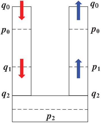
Figure 2: Schematic diagram of the discretized hydraulic model for the Dual-layer Pipe system
Based on the discretized finite difference equations, a bottomhole pressure calculation model for deepwater Dual-layer Pipe dual-gradient drilling (DGD) systems is established. The drilling pump outlet pressure is expressed as:
In the equation,
The flow rate variation at the lift pump discharge outlet is given by:
In the equation,
The frictional pressure loss can be determined from the empirical pipe flow equation as:
In the equation,
The pressure drop characteristic of the lift pump is empirically modeled as a polynomial function of the inlet flow rate through field data regression analysis:
In the equation,
The dynamic pressure response at the lift pump discharge during operational conditions is expressed as:
In the equation,
The discharge flow dynamics of the lift pump during drilling fluid circulation is mathematically expressed as:
In the equation,
The pressure loss across the drill bit is formulated as [23]:
In the equation,
The frictional pressure loss is determined by the following governing equation:
In the equation,
The lifting pressure generated by the lift pump contributes to bottomhole pressure reduction. The pump head, being primarily dependent on the return drilling fluid flow rate, is calculated as follows:
In the equation,
The choke valve is installed at the wellhead between the Dual-layer Pipe inner string and surface manifold. By adjusting the choke opening, the wellhead backpressure can be modulated to regulate bottomhole pressure. After the drilling fluid passes through the downhole hydraulic lift pump, with the choke opening held constant, the return flow rate can be considered invariant. Under these conditions, the bottomhole pressure variation in the Dual-layer Pipe system under the influence of the lift pump is expressed as:
In the equation,
The flow rate through the choke valve is given by:
In the equation,
The flow rate from the bottomhole into the outer annulus is expressed as:
In the equation,
The frictional pressure loss per unit length in the outer annulus can be expressed as:
In the equation,
The variation in fluid column height within the outer annulus can be mathematically expressed as:
During drilling operations, the spacer fluid column maintains nearly constant length. Consequently, the seawater column height in the outer annulus is given by:
In the equation,
Under constant flow rate conditions at the surface drilling pump, dynamic adjustment of the choke valve opening enables real-time modulation of both wellhead backpressure and bottomhole pressure (excluding analysis of localized flow resistance effects). During drilling operations, the internal pressure within the Dual-layer Pipe inner string varies with well depth, as calculated by [24,25]:
In the equation,
3 Backpressure Regulation-Based Bottomhole Pressure Control Method
In the backpressure regulation system for deepwater Dual-layer Pipe dual-gradient drilling, the automated choke manifold serves as the core component with its choke valve being the critical equipment for pressure control. This system maintains dynamic balance of bottomhole pressure by continuously comparing actual measurements with target values and precisely adjusting the choke valve opening based on the pressure difference. The relationship between pressure differential across the choke valve and its relative opening exhibits five characteristic flow regulation patterns [26] (as shown in Fig. 3): quick-opening, square root, linear, equal percentage, and parabolic. Since the choke valve opening has minimal effect on drilling fluid flow rate, the flow is generally treated as constant when analyzing the valve characteristics.
Figure 3: Schematic diagram of choke valve pressure characteristics
The flow characteristic curve of the choke valve is expressed as a function of the valve opening degree and the pressure differential across the valve:
In the equation,
At a given initial operating point
Expanding the above equation as a Taylor series about a given operating point yields:
Subtracting Eq. (22) from Eq. (23) yields:
During deepwater Dual-layer Pipe dual-gradient drilling operations, assuming constant drilling fluid flow rate, the following relationship holds:
In the equation,
From the functional relationship between valve opening degree (
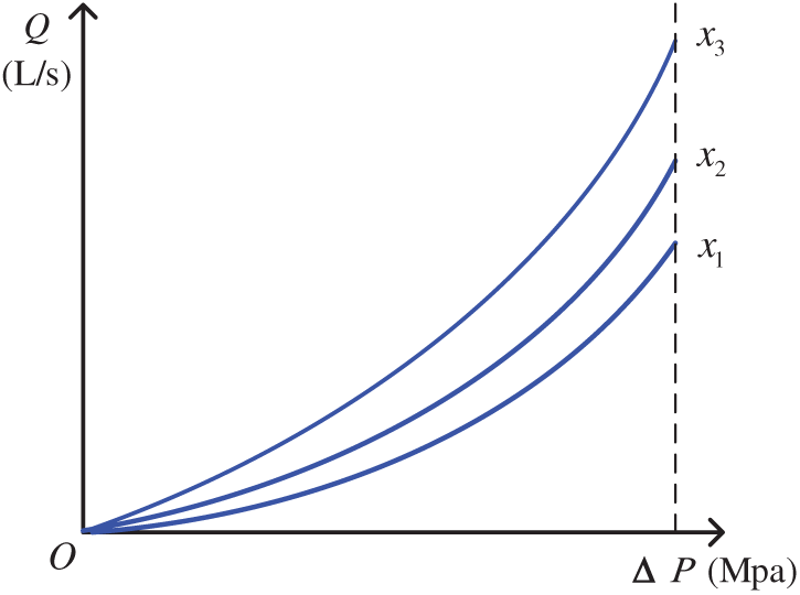
Figure 4: Relationship between flow rate through the choke valve and pressure differential (x1 < x2 < x3)
The characteristic curve of flow rate vs. valve opening degree provided by the choke valve manufacturer is shown in Fig. 5 [27]:

Figure 5: Flow rate vs. opening degree characteristic curve for the choke valve (
Within the operational range
By substituting Eqs. (28) and (29) into Eq. (27), we obtain:
Given that
This leads to the following derivation:
Integrating Eq. (32) yields:
Parameters C and m are determined based on a set of results obtained from laboratory experiments or field commissioning, which are then used to establish the control equation for the choke valve. In petroleum drilling systems, the value of C typically falls within the range of approximately 1 to 20, while m is a positive number [28]. During back-pressure regulation, by considering the requirements for the choke valve’s flow rate and pressure differential, an appropriate choke valve opening position can be promptly identified. This provides theoretical support for rapid positioning control in throttle pressure regulation.
The bottomhole pressure (BHP) is influenced by the choke valve opening. As the choke valve opening changes, the bottomhole pressure varies accordingly. The initial bottomhole pressure can be derived from Eq. (20). Consequently, the bottomhole pressure can be expressed as:
Based on the unique three-channel flow characteristics of the Dual-layer Pipe, it can be observed that as the bottomhole pressure (BHP) changes, the fluid levels of seawater, spacer fluid, and drilling mud in the outer annulus also vary accordingly.
When fluid flows through the inner conduit of the Dual-layer Pipe, the back-pressure (i.e., external pressure applied at the wellhead) is transmitted to the bottomhole via the hydrodynamic flow of the drilling mud. The pressure differential generated by this back-pressure acts on the bottomhole fluid, thereby altering the bottomhole pressure (BHP). This pressure transmission occurs through hydraulic conductivity within the fluid column, resulting in a direct equivalence between back-pressure variations and corresponding changes in BHP [29]. In practical drilling operations, the spacer fluid column’s vertical extent (relative to the seawater and drilling mud columns in the annuli) is typically negligible due to its minimal volume. Based on the principle of hydrostatic pressure equilibrium, the following relationship can be derived:
The mathematical model describing the relationship between the choke valve opening degree and the variation in the spacer fluid level can be derived by solving the system of equations formed by Eqs. (36) and (33) simultaneously.
3.2 Choke Pressure Control System
During drilling operations, bottomhole pressure (BHP) is highly susceptible to parameter variations and disturbances, leading to dynamic changes in control characteristics. To address this, adaptive control is employed, leveraging modern control theory to perform online parameter identification of the drilling system and dynamically adjust control strategies in real-time, thereby ensuring that BHP remains within the desired operational range. However, the efficacy of BHP regulation hinges on the accuracy of both hydraulic models (describing fluid flow and pressure propagation) and automatic control models (defining feedback mechanisms). This poses significant challenges for analytical modeling of complex drilling fluid circulation systems and surface pressure control devices, particularly under deepwater drilling conditions with dual-gradient requirements [30,31]. Therefore, for deepwater Dual-layer Pipe dual-gradient drilling operations, a PID (Proportional-Integral-Derivative) control algorithm is adopted. The controller establishes a feedback model by correlating the control error (the deviation between the setpoint bottomhole pressure and the measured bottomhole pressure) with the corrective output. The overall structure of the closed-loop feedback system is shown in Fig. 6.

Figure 6: Block diagram of PID-based closed-loop feedback control system
The setpoint bottomhole pressure (BHP) defined upstream of the choke valve is denoted as
The proportional, integral, and derivative components of the control error are linearly combined to generate the control signal for adjusting the choke valve opening. Mathematically, this is expressed as:
In the equation,
After applying the Laplace transform to Eq. (39), it can be expressed in transfer function form as:
where s represents the complex frequency variable in the Laplace transform.
3.2.2 Fuzzy-PID Control Algorithm
The Fuzzy Algorithm is a computational method capable of accurately processing chaotic, uncertain data and outputting conclusions or solutions. Its core mechanism leverages fuzzy sets—specifically, pixel-level membership distributions (derived from Laplacian-processed and linearly transformed node configurations)—to transform complex, indeterminate data into a computable fuzzy objective function [32,33].
As shown in Fig. 7, the fuzzy controller consists of four modules: fuzzification, fuzzy inference, fuzzy control rule base and fuzzy judgment. When controlling, the fuzzy experience is converted into fuzzy rules first, and the detection element compares the actual output with the given value to get the deviation e, and then fuzzifies e and its rate of change ec to get the fuzzy quantity as the fuzzy rule input, and then gets the precise quantity through fuzzy reasoning and defuzzification, and delivers it to the actuator to control the object. The fuzzy inference module of the controller is shown in Fig. 8.

Figure 7: Fundamental principles of fuzzy control

Figure 8: Fuzzy inference block
3.3 Fuzzy-PID Controller Design
In deepwater Dual-layer Pipe dual-gradient drilling (DGD) systems, variations in choke valve opening directly modulate bottomhole pressure (BHP). As illustrated in Fig. 9, a fuzzy-PID controller is developed by integrating computational data with fuzzy algorithms to precisely regulate wellbore pressure. Compared to conventional PID control, this fuzzy-PID approach achieves superior pressure control accuracy by dynamically adjusting parameters to address the inherent limitations of fixed-gain controllers. By calculating the control system deviation e and deviation rate ec, the rules of the fuzzy inference system are used to adjust kp, ki, and kd, and the throttle valve opening is controlled to change the backpressure, so that the bottomhole pressure is stabilized at the set value.

Figure 9: Principle of fuzzy-PID control
(1) Domain Quantization
For deepwater Dual-layer Pipe dual-gradient drilling, analyze the bottomhole pressure and choke backpressure. The preset bottomhole pressure deviation (e) and its rate of change (ec) serve as the inputs to the controller, while the adjusted variations of the three parameters are the outputs of the fuzzy PID controller. Both input and output variables use the fuzzy subset linguistic terms: {NB (Negative Big), NM (Negative Medium), NS (Negative Small), ZO (Zero), PS (Positive Small), PM (Positive Medium), PB (Positive Big)}.
(2) Determination of the Fuzzy Subsets’ Universe of Discourse
After quantization and incremental factor calculation, the fuzzy universe of discourse for the controller deviation e is set to [−6, 6] based on the system pressure range. Similarly, the fuzzy universe of discourse for the deviation changes rate (ec) in the fuzzy PID pressure control system is also [−6, 6]. The output linguistic variables (dkp, dki, dkd) have a fuzzy universe of discourse of [−1, 1]. The quantization of the parameter domains for the fuzzy control system is summarized in Table 1.

(3) Fuzzy Representation
The use of fuzzy expressions helps determine the shape of membership functions [34]. Based on the operating condition where the bottom-hole pressure is altered by adjusting the throttle valve opening, this paper selects trapezoidal and triangular membership functions to describe fuzzy variables. Among them, the expression function of the rising semi-trapezoidal membership function is as follows:
Here, a represents the starting point where the function begins to rise; b denotes the terminal point where the function attains its maximum value of 1.
The expression function for the falling semi-trapezoidal membership function is given as follows:
In the expression, b represents the starting point of the decline phase, where the function attains its maximum value of 1. c denotes the terminal point, where the function’s value drops to 0.
The triangular membership function is defined as follows:
In the expression for the triangular membership function, a and c represent the left and right boundaries of the triangle, respectively, defining the effective range (or universe of discourse) within which the membership function holds significance. Within this interval, the function describes the gradual transition of a variable’s membership degree in a fuzzy set.
b denotes the apex (vertex) of the triangle, where the membership degree reaches its maximum value of 1, indicating the peak influence or optimal relevance of the variable within the fuzzy system.
(4) Establishment of Fuzzy Rules
Fuzzy rules constitute the core component of fuzzy control. In this system, they are primarily formulated based on the system’s operational principles and empirical knowledge. For the bottomhole pressure regulation system, the foremost consideration is maintaining the backpressure generated by the choke valve at the setpoint value, which requires keeping the system’s computational error within a minimal range. The PID parameter adjustment should adhere to the following principles:
When the error (e) is large and the error rate (ec) is negative, the system response is moving in the correct direction but still far from the setpoint. In this case, kp must be large while ki and kd should be small to quickly approach the setpoint.
When the error (e) is negative and the error rate (ec) is significant, indicating the system response has overshot the setpoint with growing deviation, the derivative gain (kd) should be increased while both the integral gain (ki) and proportional gain (kp) are reduced to effectively limit overshoot.
When the error (e) is negative while the error rate (ec) is positive, indicating the system response is approaching steady-state conditions, the proportional gain (kp) should remain sufficiently large to facilitate rapid stabilization. However, to minimize overshoot and suppress oscillations, the derivative gain (kd) must be increased while the integral gain (ki) should be reduced accordingly.
When the error (e) is significant and the error rate (ec) is positive, indicating the system exhibits negative-side overshoot, the derivative gain (kd) should be increased to reduce deviation while both the proportional gain (kp) and integral gain (ki) should also be augmented to enhance corrective action.
Based on the aforementioned principles, the fuzzy rule table for the control system can be designed as follows (Tables 2–4):


(5) Fuzzy Inference and Output Variable Defuzzification
The fuzzy inference is performed using MATLAB’s Fuzzy Logic Toolbox. After providing the inputs, fuzzification is applied to determine the fuzzy values of the output variables. The predefined fuzzy rules for Kp, Ki, and Kd are then used to obtain the fuzzy output quantities, which are subsequently defuzzified into precise numerical values for PID parameter tuning. In this study, the fuzzy rules are implemented in MATLAB’s fuzzy module to generate the output response surfaces of the fuzzy rules, as shown in Fig. 10.

Figure 10: Fuzzy rule response surfaces
This study selects a deepwater vertical well for simulation analysis, with its wellbore structure and bottomhole assembly parameters shown in the table below (Tables 5–7). The simulation models bottomhole pressure control during deepwater Dual-layer Pipe dual-gradient drilling based on 65/8 in Dual-layer Pipe dimensions, without considering rate of penetration, cuttings concentration, or surface manifold pressure losses. These simplifications were made to isolate and evaluate the performance of the fuzzy-PID controller under idealized hydraulic conditions. Future studies will consider the inclusion of rate of penetration, cuttings loading effects, and surface backpressure losses to improve model fidelity and field applicability.

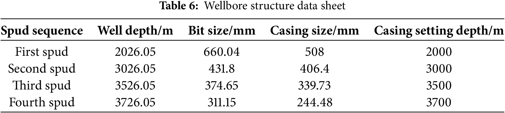

Fig. 11 reveals the pressure distribution patterns in both the outer and inner pipes of the Dual-layer Pipe system: as well depth increases, the wellbore pressure profile shows linear growth above and below the mudline. The pressure gradient in the inner pipe (12.58 kPa/m) exceeds that in the outer pipe (7.77 kPa/m). The spacer fluid separates seawater from drilling fluid, creating two distinct pressure gradients in the outer annulus. During drilling fluid circulation, the pump pressure provided by the drilling pump is 35 MPa, increasing to a maximum of 63.26 MPa in the outer pipe. Due to frictional pressure losses through the mud motor and bit, the bottomhole pressure drops to 56.4 MPa. At the 3500 m depth, the downhole lift pump reduces bottomhole pressure, causing a slight pressure discontinuity (1.76 MPa decrease) in the inner pipe. When the drilling fluid returns to the wellhead, the wellhead pressure measures 2.30 MPa.

Figure 11: Wellbore pressure profile
In the Simulink environment, based on the wellbore pressure profile, the basic system modules were combined into a specific control system, and the fuzzy control algorithm was applied as the main regulator of the bottomhole pressure model for deepwater Dual-layer Pipe dual-gradient drilling to conduct simulation studies. As shown in Fig. 12, the fuzzy control system takes the set bottomhole pressure, the error (e) between actual and target bottomhole pressures, and the error rate of change (ec) as inputs, processes them through the hydraulic model, and outputs the calculated bottomhole pressure.
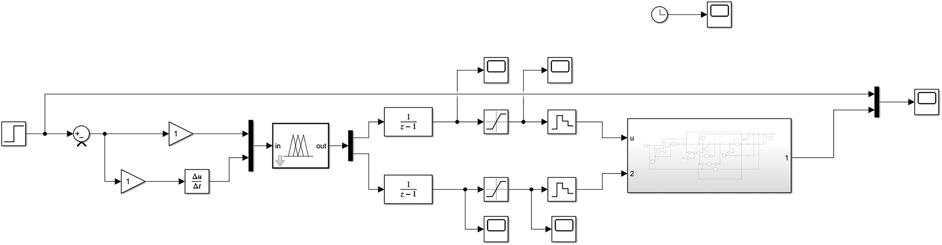
Figure 12: Simulink simulation framework diagram of the bottomhole pressure control model for deepwater Dual-layer Pipe dual-gradient drilling
In the Simulink environment, different bottomhole pressure values were adjusted to observe the step response of the controller and analyze its settling time and amplitude, thereby evaluating the performance of the bottomhole pressure control system for deepwater Dual-layer Pipe dual-gradient drilling. Figs. 13 and 14 display the step response curves after increasing the target bottomhole pressure by 1 and 2 MPa, respectively. The results show that the fuzzy-PID control parameters are properly configured, enabling rapid pressure stabilization with minimal influence from the pressure setpoint. Over time, both the bottomhole pressure and spacer fluid level stabilize, with maximum pressure error of 0.12% and maximum spacer level variation of 25.81 m, meeting field operational requirements.

Figure 13: Bottomhole pressure and spacer fluid level control effect (1 MPa increase)

Figure 14: Bottomhole pressure and spacer fluid level control effect (2 MPa increase)
When the target bottomhole pressure is decreased by 1 MPa and then immediately increased by 1 MPa, the fuzzy-PID control effect is shown in Fig. 15. The results demonstrate that the fuzzy-PID control parameters are properly configured, enabling rapid pressure stabilization with minimal influence from the pressure setpoint changes during the pressure reduction-followed-by-increase process.

Figure 15: Bottomhole pressure and spacer fluid level control effect (1 MPa decrease followed by 1 MPa increase)
Considering that in actual deepwater Dual-layer Pipe dual-gradient drilling operations, target pressure may be set not only directly but also in stepwise changes, the target pressure was increased stepwise from 56.47 to 59.47 MPa and then decreased stepwise from 59.47 MPa back to 56.47 MPa, with the fuzzy control response curve shown in Fig. 16.

Figure 16: Step response curves of control performance during continuous bottomhole pressure adjustments
The results show that when the target pressure increases stepwise, the fuzzy-PID control responds rapidly with minor overshoot (<5%) at each target pressure point, all within controllable limits. The pressure quickly converges to the target, stabilizing at 59.47 MPa within 232 s. Similarly, during stepwise pressure reduction, the fuzzy-PID control ensures prompt stabilization at the set pressure.
As shown in Fig. 17, the response performance of the fuzzy-PID control system is compared directly with that of a conventional PID controller under identical bottomhole pressure variation scenarios. The results indicate that the fuzzy-PID control achieves more rapid convergence to the target pressure, with reduced overshoot and minimal oscillation. Quantitatively, the fuzzy-PID system maintains overshoot below 5% and steady-state error below 0.12%, whereas the conventional PID controller shows a slower response with larger deviation from the setpoint. These results confirm that the fuzzy-PID algorithm enhances both control accuracy and anti-interference capability, making it more suitable for dynamic regulation in deepwater dual-gradient drilling operations.
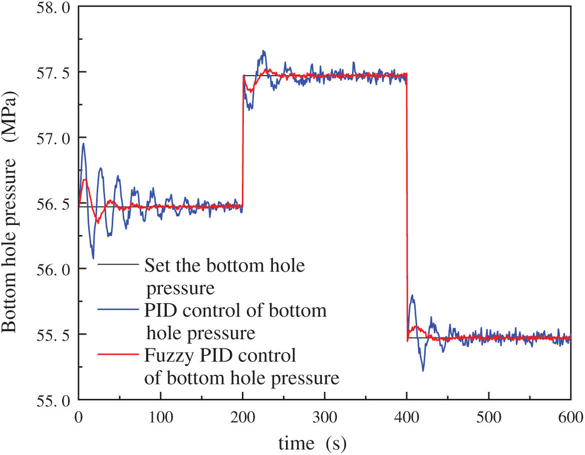
Figure 17: Quantitative comparison of bottomhole pressure responses under PID and fuzzy-PID control strategies
(1) Based on the unique flow channels of Dual-layer Pipe systems and the characteristics of downhole lift pumps, a bottomhole pressure calculation model was established for deepwater Dual-layer Pipe dual-gradient drilling. The study revealed the dynamic variation patterns of bottomhole pressure during this process, providing theoretical foundation for optimizing backpressure regulation control methods.
(2) A backpressure regulation control system was designed based on the coupling relationship between choke valve opening, surface backpressure, and bottomhole pressure. By incorporating fuzzy control theory with PID controllers, it dynamically adjusts control parameters to precisely regulate choke valve opening and generate backpressure, ensuring bottomhole pressure remains within the safe density window. This system effectively addresses response lag and precision limitations of conventional methods, demonstrating strong robustness and adaptability to complex drilling conditions.
(3) Multi-condition simulation analysis of the designed control system was conducted on the Simulink platform. The results demonstrate that the fuzzy-PID control system rapidly responds to bottomhole pressure variations while maintaining pressure near setpoints, with overshoot below 5% and steady-state error under 0.12%. The simulation results validate the effectiveness and stability of the proposed method under complex drilling conditions, highlighting its practical potential for deepwater drilling applications.
(4) It is worth noting that the proposed bottomhole pressure control system is currently at the prototype testing stage and has not yet been deployed in field operations. Therefore, this study focuses primarily on the theoretical framework, control methodology, and simulation-based validation of the system. While practical deployment challenges—such as real-time sensor feedback, actuator response latency, and integration with existing rig infrastructure—are acknowledged, a detailed economic analysis is beyond the current scope. Future work will explore hardware-in-the-loop testing and practical implementation feasibility once the system reaches a more mature stage.
Acknowledgement: The authors would like to express their sincere appreciation to the technical staff and administrative team of the Drilling Engineering Research Center at Southwest Petroleum University for their invaluable support in data organization and experimental coordination. The authors also acknowledge the assistance provided by the university’s High-Performance Computing Center for simulation resources. Additionally, the provision of field parameters and engineering data from collaborative industry partners is gratefully acknowledged.
Funding Statement: This work is supported by the Sichuan Provincial Key R&D Program (Regional Innovation Cooperation Project 2025YFHZ0306); Open Fund (PLN 2022-46) of State Key Laboratory of Oil and Gas Reservoir Geology and Exploitation (Southwest Petroleum University); Special Support for Sichuan Postdoctoral Research Projects.
Author Contributions: Xin Liu: Writing—original draft, Validation, Methodology, Formal analysis, Data curation. Zheng Zhang: Supervision, Funding acquisition. Yu Zhao: Data curation. Yi Yang: Software, Resources. Zhenning Qiao: Validation, Conceptualization. Zhibo Xu: Formal analysis, Conceptualization. Xianzhi Yu: Supervision, Formal analysis, Conceptualization. All authors reviewed the results and approved the final version of the manuscript.
Availability of Data and Materials: No data was used for the research described in the article.
Ethics Approval: This study does not involve human participants, animals, or sensitive data, and therefore does not require ethical approval.
Conflicts of Interest: The authors declare no conflicts of interest to report regarding the present study.
References
1. Rehman A, Ghias R, Ahmad I, Iqbal Sherazi H. Advance optimized nonlinear control strategies for manage pressure drilling. IEEE Access. 2024;12:73436–50. doi:10.1109/access.2024.3404054. [Google Scholar] [CrossRef]
2. Jia CZ. Prospects of China’s petroleum upstream industry and five major theoretical and technological challenges for the future. Acta Petrolei Sinica. 2024;45(1):1–14. doi:10.7623/syxb202401001. [Google Scholar] [CrossRef]
3. Dou L, Wen Z, Wang J, Wang Z, He Z, Liu X, et al. Analysis of the world oil and gas exploration situation in 2021. Petrol Explor Dev. 2022;49(5):1195–209. doi:10.1016/s1876-3804(22)60343-4. [Google Scholar] [CrossRef]
4. Wen Z, Wang J, Wang Z, He Z, Song C, Liu X, et al. Analysis of the world deepwater oil and gas exploration situation. Petrol Explor Dev. 2023;50(5):924–36. doi:10.1016/s1876-3804(23)60449-5. [Google Scholar] [CrossRef]
5. Zhang Z, Yang Y, Qu Q, Li Y, Zhao Y, Xu Z, et al. Innovations and challenges in deepwater dual-gradient drilling: a review of current technologies and future directions. Geoenergy Sci Eng. 2025;250(3):213829. doi:10.1016/j.geoen.2025.213829. [Google Scholar] [CrossRef]
6. Wang C, Xia Y, Zeng Q, Ma J, Wang G, Gou J, et al. Dynamic risk analysis of deepwater gas hydrate drilling with a riserless drilling system based on uncertain dynamic Bayesian network model. ASCE-ASME J Risk Uncertainty Eng Syst, Part A Civ Eng. 2022;8(1):05021006. doi:10.1061/ajrua6.0001206. [Google Scholar] [CrossRef]
7. Wang C, Xia Y, Wang D, Niu Z, Liu Y, Yu C. Dynamic risk assessment of deep-water dual gradient drilling with SMD system using an uncertain DBN-based comprehensive method. Ocean Eng. 2021;226(8):108701. doi:10.1016/j.oceaneng.2021.108701. [Google Scholar] [CrossRef]
8. Schumacher JP, Dowell JD, Ribbeck LR, Eggemeyer JC. Subsea mudlift drilling: planning and preparation for the first subsea field test of a full-scale dual gradient drilling system at green canyon 136, Gulf of Mexico. In: SPE Annual Technical Conference and Exhibition; 2001 Sep 30–Oct 3; New Orleans, LA, USA. SPE-71358-MS. doi:10.2118/71358-ms. [Google Scholar] [CrossRef]
9. Vieira P, Arnone M, Russel B, Cook I, Moyse K, Torres F, et al. Constant bottomhole pressure: managed-pressure drilling technique applied in an exploratory well in Saudi Arabia. In: SPE/IADC Managed Pressure Drilling and Underbalanced Operations Conference and Exhibition; 2008 Jan 28–29; Abu Dhabi, United Arab Emirates. SPE-113679-MS. doi:10.2118/113679-ms. [Google Scholar] [CrossRef]
10. Totland JFH. Fast pressure control in managed pressure drilling [Ph.D. thesis]. Trondheim, Norway: Institutt for teknisk kybernetikk; 2014. [Google Scholar]
11. Kaasa GO, Stamnes ØN, Aamo OM, Imsland LS. Simplified hydraulics model used for intelligent estimation of downhole pressure for a managed-pressure-drilling control system. SPE Drill Complet. 2012;27(1):127–38. doi:10.2118/143097-pa. [Google Scholar] [CrossRef]
12. Kokkinis A, Frantzis T, Skordis K, Nikolakopoulos G, Koustoumpardis P. Review of automated operations in drilling and mining. Machines. 2024;12(12):845. doi:10.3390/machines12120845. [Google Scholar] [CrossRef]
13. Li R, Yuan W, Ding X, Xu J, Sun Q, Zhang Y. Review of research and development of hydraulic synchronous control system. Processes. 2023;11(4):981. doi:10.3390/pr11040981. [Google Scholar] [CrossRef]
14. Li G, Song X, Tian S, Zhu Z. Intelligent drilling and completion: a review. Engineering. 2022;18(2):33–48. doi:10.1016/j.eng.2022.07.014. [Google Scholar] [CrossRef]
15. Zhou J, Nygaard G. Automatic model-based control scheme for stabilizing pressure during dual-gradient drilling. J Process Control. 2011;21(8):1138–47. doi:10.1016/j.jprocont.2011.06.022. [Google Scholar] [CrossRef]
16. Hauge E, Aamo OM, Godhavn JM, Nygaard G. A novel model-based scheme for kick and loss mitigation during drilling. J Process Control. 2013;23(4):463–72. doi:10.1016/j.jprocont.2013.01.006. [Google Scholar] [CrossRef]
17. Nazir S, Ashraf N, Ahmad I. Backstepping based control of heave-induced pressure deviations in managed pressure drilling. In: 2016 UKACC 11th International Conference on Control (CONTROL); 2016 Aug 31–Sep 2; Belfast, UK. p. 1–6. doi:10.1109/CONTROL.2016.7737518. [Google Scholar] [CrossRef]
18. Wang JS, Li J, Liu GH, Huang T, Yang HW. Parameters optimization in deepwater dual-gradient drilling based on downhole separation. Petrol Explor Dev. 2019;46:776–81. (In Chinese). doi:10.1016/s1876-3804(19)60240-5. [Google Scholar] [CrossRef]
19. Zhang W, Zhang J, Wang Z, Sun R, Yu S, Yang Z. Flow regulation and bottom hole pressure control under gas influx condition based on RMR system. J Phys Conf Ser. 2022;2280(1):012050. doi:10.1088/1742-6596/2280/1/012050. [Google Scholar] [CrossRef]
20. Pei Y, Liu Q, Wang C, Wang G. Energy-efficient pressure regulation model and experiment of lift pump system in deepwater dual-gradient drilling. J Petrol Sci Eng. 2021;203(9):108621. doi:10.1016/j.petrol.2021.108621. [Google Scholar] [CrossRef]
21. Landet IS, Pavlov A, Aamo OM. Modeling and control of heave-induced pressure fluctuations in managed pressure drilling. IEEE Trans Control Syst Technol. 2013;21(4):1340–51. doi:10.1109/TCST.2012.2204751. [Google Scholar] [CrossRef]
22. Wang G, Lv Z, Zhong L, Li Z, Fu Q, Li Y, et al. Hydraulic modeling study and control algorithm design of double-layer pipe dual-gradient drilling. Geoenergy Sci Eng. 2024;240:212926. doi:10.1016/j.geoen.2024.212926. [Google Scholar] [CrossRef]
23. Zhang J, Mao GZ, Li X, Sun XF. Lifting efficiency of drilling fluid of submarine pump lifting system in return line. Sci Technol Eng. 2020;20:3024–8. (In Chinese). [Google Scholar]
24. Wang G, Lv Z, Zhong L, Li Z, Fu Q, Li Y, et al. Double-layer pipe dual-gradient drilling wellbore pressure calculation model and parameters optimization. Geoenergy Sci Eng. 2023;230(2):212249. doi:10.1016/j.geoen.2023.212249. [Google Scholar] [CrossRef]
25. Ren M, Zhang X, Xie R, Wang J, Zhu Z, Cheng X, et al. Study on the equivalent density tool and depressurisation mechanism of suction-type depressurisation cycle. Processes. 2024;12(9):2017. doi:10.3390/pr12092017. [Google Scholar] [CrossRef]
26. Tang Y, Zhou M, Liu X, Li G, Wang Q, Wang G. Study on throttling pressure control flow field for traction speed regulation and braking mechanism of the pipeline intelligent plugging robot. Energy. 2023;282(2):128331. doi:10.1016/j.energy.2023.128331. [Google Scholar] [CrossRef]
27. Siahaan HB, Jin H, Safonov MG. An adaptive PID switching controller for pressure regulation in drilling. IFAC Proc. 2012;45(8):90–4. doi:10.3182/20120531-2-NO-4020.00017. [Google Scholar] [CrossRef]
28. Wang X, Hasan AR, Zhang B, ke K, Wang Y, Zhang P. Study on the hydrate formation region in a wellbore during Subsea Mudlift Drilling. Simulation. 2021;97(2):69–82. doi:10.1177/0037549719831359. [Google Scholar] [CrossRef]
29. Pazoki D, Nikoofard A, Sedigh AK. Heave attenuation in offshore managed pressure drilling with an integral sliding mode controller. Appl Ocean Res. 2024;145(1):103932. doi:10.1016/j.apor.2024.103932. [Google Scholar] [CrossRef]
30. Gorjizadeh H, Ghalehnoie M, Negahban S, Nikoofard A. Fuzzy controller design for constant bottomhole pressure drilling under operational/physical constraints. J Petrol Sci Eng. 2022;212:110335. doi:10.1016/j.petrol.2022.110335. [Google Scholar] [CrossRef]
31. Lordejani SN, Besselink B, Abbasi MH, Kaasa GO, Schilders WHA, van de Wouw N. Control-oriented modeling for managed pressure drilling automation using model order reduction. IEEE Trans Contr Syst Technol. 2021;29(3):1161–74. doi:10.1109/tcst.2020.2994535. [Google Scholar] [CrossRef]
32. Lordejani SN, Abbasi MH, Velmurugan N, Berg C, Stakvik JÅ, Besselink B, et al. Modeling and numerical implementation of managed-pressure-drilling systems for the assessment of pressure-control systems. SPE Drill Complet. 2020;35(4):598–619. doi:10.2118/201108-pa. [Google Scholar] [CrossRef]
33. Amiri S. Scrutinizing the influence of an adaptive fuzzy sliding mode control strategy on the regulation of constant BHP control. Geoenergy Sci Eng. 2024;241(1):213110. doi:10.1016/j.geoen.2024.213110. [Google Scholar] [CrossRef]
34. Yang HW, Li J, Jiang JW, Zhang H, Guo BY, Zhang G, et al. A dynamic managed pressure well-control method for rapid treatment of gas kick in deepwater managed pressure drilling. Petrol Sci. 2022;19(5):2297–313. doi:10.1016/j.petsci.2022.06.011. [Google Scholar] [CrossRef]
Cite This Article
 Copyright © 2025 The Author(s). Published by Tech Science Press.
This work is licensed under a Creative Commons Attribution 4.0 International License , which permits unrestricted use, distribution, and reproduction in any medium, provided the original work is properly cited.
 Downloads
 Citation Tools