
 Submit a Paper
 Propose a Special lssue
 Open Access
ARTICLE

Planning and Evaluation Method of MMC-MTEDC Network Construction of Urban Power Grid
1 Shenzhen Power Supply Co., Ltd., Shenzhen, 518000, China
2 College of Electrical Engineering, Zhejiang University, Hangzhou, 310027, China
* Corresponding Author: Ying Huang. Email:
Energy Engineering 2025, 122(11), 4475-4495. https://doi.org/10.32604/ee.2025.068711
Received 04 June 2025; Accepted 29 July 2025; Issue published 27 October 2025
 View Full Text
 Download PDF
Abstract
With the accelerating urbanization process, the load demand of urban power grids is constantly increasing, giving rise to a batch of ultra-large urban power grids featuring large electricity demand, dense load distribution, and tight construction land constraints. This paper establishes a network planning method for urban power grids based on series reactors and MMC-MTEDC, focusing on four aspects: short-circuit current suppression, accommodation of external power supply, flexible inter-regional power support, and voltage stability enhancement in load centers. It proposes key indicators including node short-circuit current margin, line thermal stability margin, maximum fault-induced regional power loss, and voltage recovery time, thereby constructing an evaluation system for MMT-MTEDC network planning in urban power grids. Based on the Shenzhen power grid planning data, simulations using DSP software reveal that series reactors reduce short-circuit current by up to 5.0%, while the MMC-MTEDC system enhances node short-circuit margins by 4.2–12.9% and shortens voltage recovery time by 19.8%. Additionally, the MMC-MTEDC system maintains 3.34–6.76 percentage points higher thermal stability margins than conventional AC systems and enables complete avoidance of external power curtailment during N-2 faults via power reallocation between terminals. Compared with traditional AC or point-to-point HVDC schemes, the proposed hybrid planning method better adapts to the spatial and reliability demands of ultra-large receiving-end grids. This methodology provides practical insights into coordinated AC/DC development under high load density and strong external power reliance. Future work will extend the approach to include electromagnetic transient constraints and lightweight MMC station designs for urban applications.Keywords
With the advancement of the Guangdong-Hong Kong-Macao Greater Bay Area national strategy, Shenzhen, as a core engine city, exhibits characteristics typical of ultra-large urban receiving-end grids, including high load density and a significant reliance on external power sources [1]. By 2024, Shenzhen’s grid peak load exceeded 23,000 MW, with a load density of 11 MW/km2, making the power supply capacity in densely populated areas a critical priority. External power sources account for over 70% of Shenzhen’s total supply, necessitating safe and efficient integration of large-scale external power [2].
However, challenges arise due to the scarcity of land for new substations in urban centers and the severe limitations on AC transmission corridors [3]. The enhancement of AC transmission capacity and short-circuit current suppression exhibit an antagonistic relationship, exacerbating the risk of short-circuit current exceedances in major urban grid lines. Under the traditional hierarchical and partitioned structure, large-scale external power must be accommodated via the 500 kV grid, increasing its burden and hindering precise power delivery to high-load-density areas. Additionally, the lack of dynamic reactive power support in load centers under AC transmission modes significantly raises the probability of transient voltage instability [4]. These issues render the conventional AC grid expansion model inadequate for meeting the rapid development demands of ultra-large urban power grids.
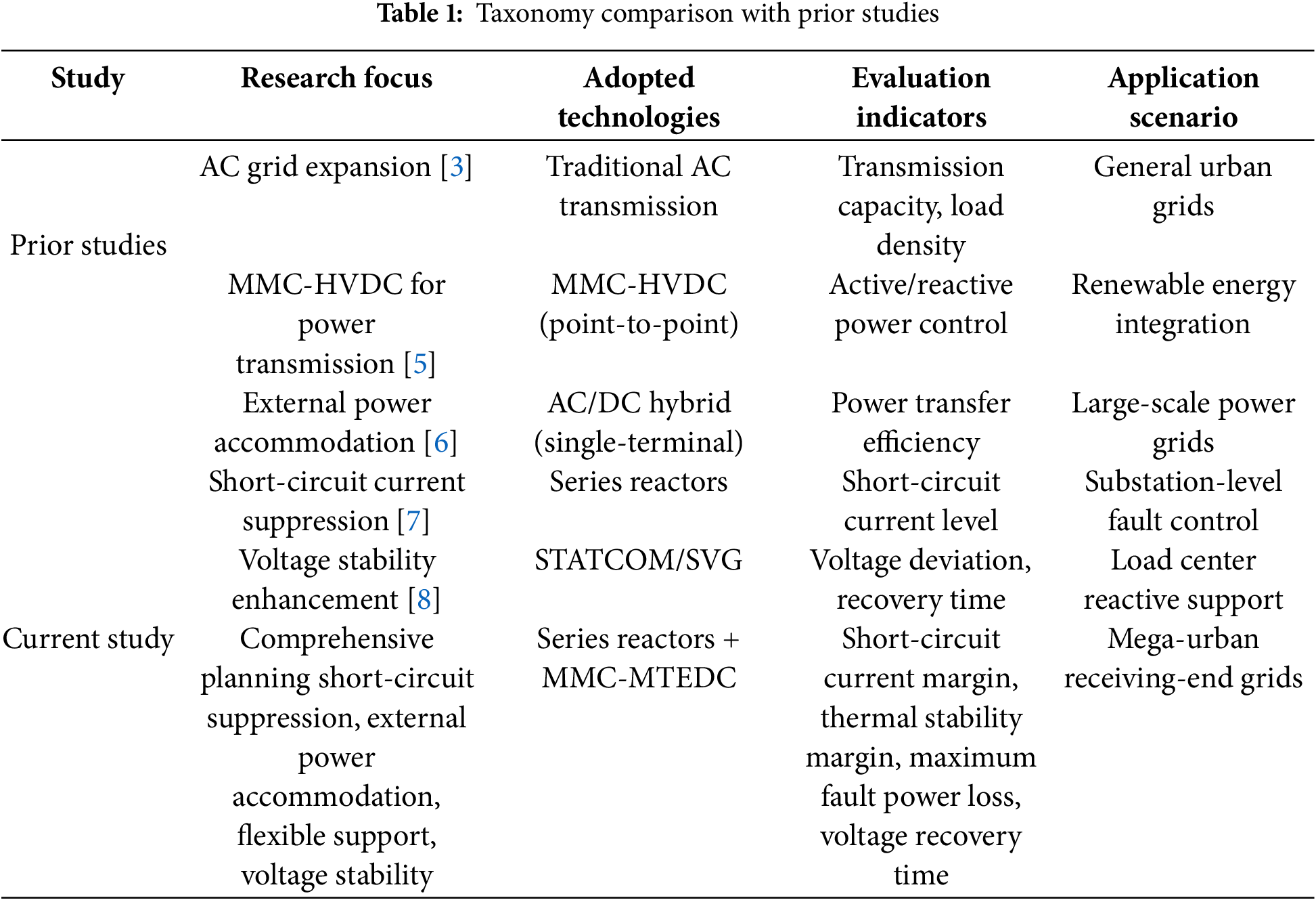
As shown in Table 1: Taxonomy Comparison with Prior Studies, prior studies have predominantly focused on single aspects of urban power grid optimization, such as AC grid expansion [3], point-to-point MMC-HVDC applications [5], or isolated short-circuit current suppression [7]. Few studies have addressed the synergistic challenges of short-circuit current control, large-scale external power integration, and flexible inter-regional support simultaneously. Notably, none have integrated series reactors with MMC-MTEDC to form a unified planning framework, nor have they established a multi-dimensional evaluation system covering short-circuit margin, thermal stability, fault loss, and voltage recovery. Our work fills this gap by systematically addressing these interconnected challenges, specifically tailored to the needs of mega-urban receiving-end grids like Shenzhen.
The novelty of this study lies in the integration of series reactors with MMC-MTEDC to form a unified planning framework, which systematically addresses four critical challenges: short-circuit current suppression, large-scale external power accommodation, flexible inter-regional power support, and voltage stability enhancement in load centers. Unlike conventional methods focusing solely on MTDC control or reactive compensation, the proposed evaluation system introduces multi-dimensional metrics—including node short-circuit current margin, line thermal stability margin, maximum fault-induced regional power loss, and voltage recovery time—to quantify the synergistic effects of hybrid AC/DC planning in urban grids.
Against this backdrop, the development of a new grid architecture capable of overcoming the physical constraints of traditional AC systems while addressing high external power reliance, high load density, and high-power quality requirements has become a crucial task for ensuring energy security and sustainable development in Shenzhen [9].
The modular multilevel converter-based multi-terminal embedded DC transmission system (MMC-MTEDC) is an advanced DC transmission technology utilizing voltage source converter (VSC). By interconnecting three or more converter stations to form a DC grid, MMC-MTEDC embeds multiple MMC-HVDC stations into the receiving-end grid, enabling efficient external power transmission and flexible power distribution [5]. This system supports dynamic integration and power flow control of distributed energy resources such as wind and solar [10], offering the following advantages:
1. Multi-terminal interconnection capability: Enables collaborative operation among multiple sending and receiving ends through mesh or hybrid topologies, overcoming the limitations of traditional point-to-point DC transmission.
2. Flexible control characteristics: Facilitates independent regulation of active/reactive power, rapid suppression of grid fluctuations, and fault isolation, enhancing dynamic response capabilities.
3. Embedded integration design: Converter stations can be directly embedded into existing AC grids, reducing retrofit costs and spatial requirements.
4. Broad applicability: Supports long-distance bulk power transmission, high-penetration renewable energy integration, and urban grid expansion, addressing stability, flexibility, and power quality bottlenecks in traditional AC systems.
While MMC-MTEDC significantly enhances grid strength in terms of external power integration [6], power exchange, and voltage support, it does not effectively mitigate short-circuit currents. The addition of series reactors can reduce short-circuit currents but may impact voltage stability [7].
This paper proposes a novel planning and evaluation methodology specifically designed for MMC-MTEDC integrated urban grids. The methodology integrates series reactor placement with MMC-MTEDC network design, supported by a new set of evaluation indicators to address short-circuit current limitations, external power accommodation, and voltage stability challenges in high-load-density cities. Key evaluation indicators are introduced, and simulations using DSP software on Shenzhen’s grid planning data demonstrate the method’s effectiveness. Simulation results show that series reactors reduce short-circuit currents by up to 5.0%, while MMC-MTEDC shortens voltage recovery time by 19.8% and enhances key node short-circuit margins by 4.2%–12.9% compared to traditional AC schemes. Notably, the MMC-MTEDC system maintains thermal stability margins 3.34–6.76 percentage points higher than AC systems during power exchange. This work provides a comprehensive planning framework for urban grids facing high load density and external power integration challenges.
2 Basic Structure and Control Methods of MMC-HVDC Systems
The modular multilevel converter (MMC) employs a cascaded sub-module (SM) design in its bridge arms. Under ideal conditions, each bridge arm consists of N SMs and a series reactor. The upper and lower bridge arms form a phase unit, as shown in Fig. 1 [11]. SMs are categorized into half-bridge and full-bridge types, with the former often selected for cost efficiency. The output voltage of a single SM is denoted as Usm. MMC operates using staircase wave approximation or nearest-level modulation techniques rather than pulse-width modulation (PWM) [12].
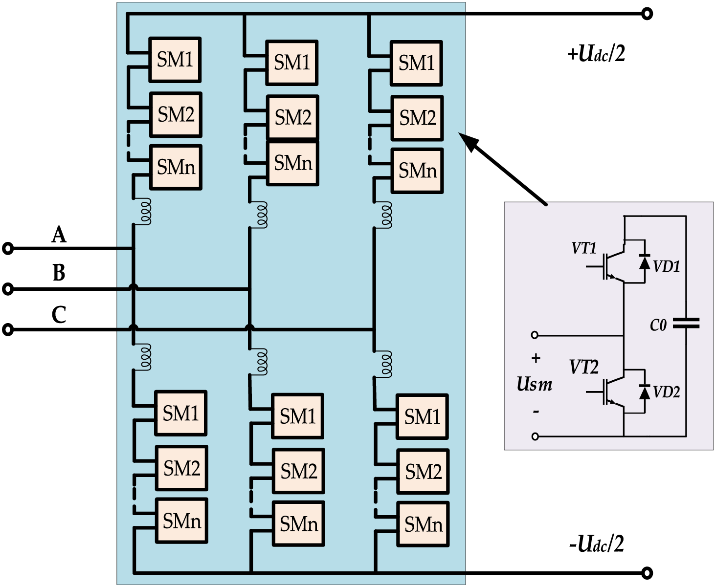
Figure 1: Basic structure diagram of Modular Multilevel Converter
2.2 Basic Control Methods of MMC
The control of MMC converters is divided into inner-loop current control and outer-loop power/voltage control. The inner-loop current controller adjusts the MMC output voltage to ensure accurate tracking of reference currents in the d-q axis. The outer-loop power controller dynamically tracks power or voltage changes, providing reference values for the inner-loop controller to ensure coordination [13].
The outer-loop power controller targets active power, DC voltage, reactive power, and AC voltage magnitude. For supplying passive or weak grids, constant V/f control is adopted [14].
2.3 Network Structure of MMC-MTEDC
Based on application scenarios, MMC-MTEDC structures are classified into two types:
1) Multi-area flexible composite networking structure: Designed to enhance internal grid characteristics by enabling flexible interconnection between 220 kV partitions while preserving the original hierarchical and zonal architecture of urban power grids. This structure facilitates zonal interconnection, power flow regulation, power exchange, and voltage support. Fig. 2 illustrates the typical topology of the multi-area flexible composite networking structure.
2) Multi-area flexible feeding structure for renewable energy clusters: Enables direct delivery of external power to multiple 220 kV load centers, reducing power losses and ensuring secure integration of external power during AC faults. This approach also alleviates the burden on the 500 kV AC transmission framework. Fig. 3 presents the typical topology of the renewable energy cluster multi-area flexible feeding structure. This configuration can be viewed as an extension of the multi-area flexible composite networking structure, incorporating sending terminals for external power while retaining the functions of zonal interconnection, power flow regulation, power exchange, and voltage support.
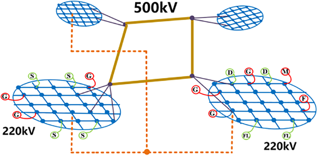
Figure 2: Multi-area flexible composite networking structure
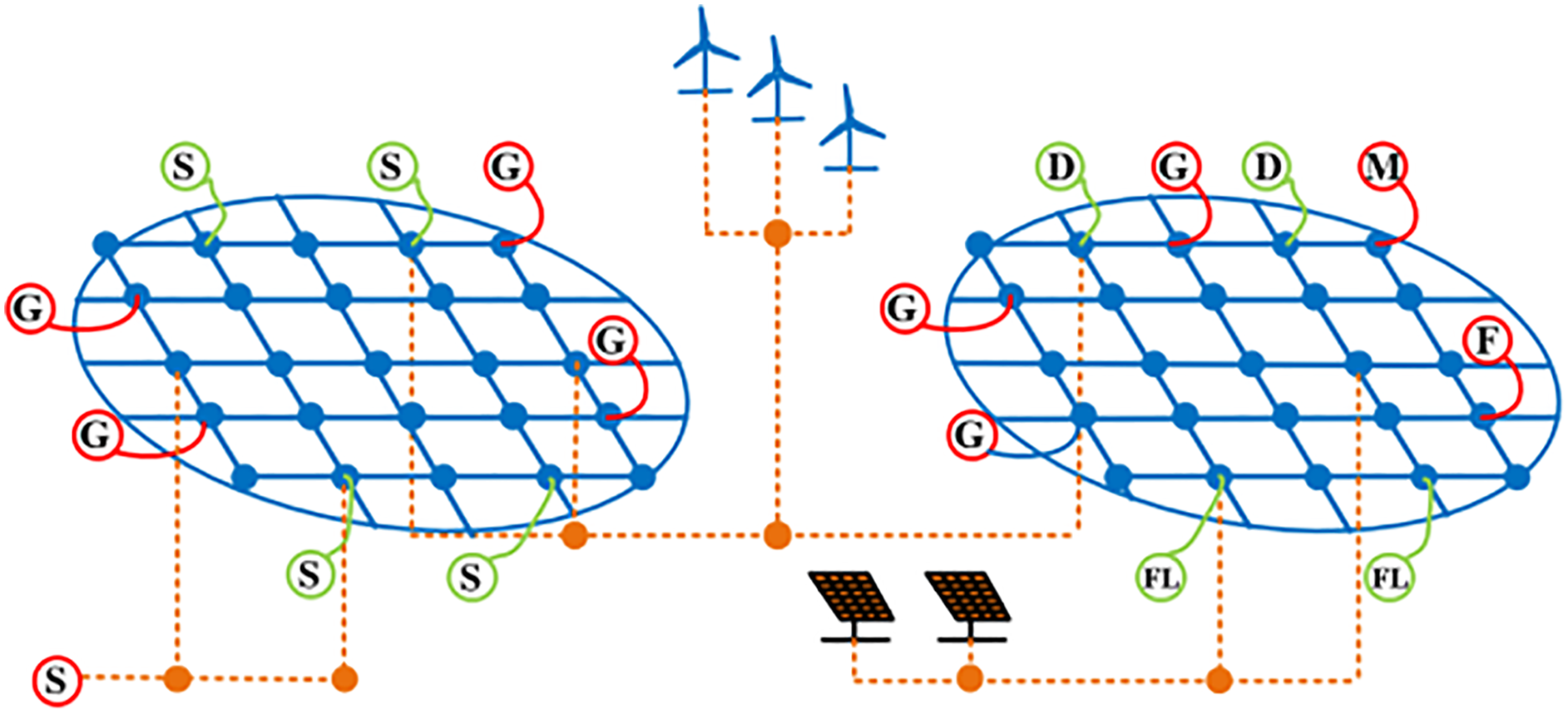
Figure 3: Multi-area flexible feeding structure for renewable energy clusters
3 Short-Circuit Current Calculation for Large-Scale Urban Power Grids
3.1 Calculation Using Node Impedance Matrix
For fault analysis using node equations, the formation of the system’s nodal admittance (or impedance) matrix is required [15]. The IEC 60909 standard provides detailed specifications for impedance calculations of various power system components, characterized by comprehensive calculation items, well-defined concepts, scientifically justified impedance corrections, and relatively conservative results [16]. The IEC standard stipulates that for all fault types (both near and far), except for zero-sequence systems, line capacitances, shunt admittances, and non-rotating loads should be neglected, and an equivalent voltage source method should be employed for short-circuit current calculations [17].
In a network under normal operating conditions, a short-circuit fault can be modeled as an additional current injection (-
where, Zij represents the mutual impedance between nodes i and j, Zif denotes the mutual impedance between node i and the fault node f after accounting for the added ground impedance.
As shown in Eq. (1), the voltage at any node i consists of two superimposed components:
1. The first term corresponds to the pre-fault voltage at node i, generated by all power sources in the network when
2. The second term represents the voltage contribution solely from the short-circuit current at node i, calculated with all current sources open-circuited and voltage sources short-circuited.
The superposition of these two components yields the actual post-fault voltage at node i:
Eq. (2) remains valid for the fault node f, yielding:
where, Zff represents the self-impedance (or input impedance) of fault node f. Eq. (3) contains two unknowns (
The simultaneous solution of Eqs. (3) and (4) gives:
When accounting for non-synchronous generation sources (e.g., MMC-HVDC and renewable energy units), Eq. (5) requires modification:
where,
The following principles govern short-circuit current calculations in China Southern Power Grid’s DSP software:
1. Static loads are considered (modeled as equivalent impedances).
2. Shunt reactive power compensation is incorporated.
3. Line charging power is accounted for.
4. MMC-HVDC systems are included in the model.
5. Contributions from renewable energy sources are evaluated.
6. STATCOM devices are considered in the analysis.
7. A short-circuit voltage coefficient of 1.08 p.u. is applied.
3.2 Short-Circuit Current Reduction via Series Reactors
3.2.1 Definition and Calculation Methods of Transfer Impedance
According to circuit theory principles, transfer impedance refers to the equivalent impedance between any two nodes in a power grid. The magnitude of this equivalent impedance serves as an indicator of the electrical distance between the nodes.
Three primary methods exist for determining transfer impedance:
1. Network Reduction Method: This approach employs series/parallel combinations and star-delta network transformations to systematically eliminate all nodes except the source node and the short-circuit node, ultimately deriving the transfer impedance between them.
2. Unit Current Calculation Method: This method proceeds by first determining the impedance of all branches in the system while setting all voltage source potentials to zero (i.e., generator terminal voltages at power plants are reduced to zero). A unit current is then injected into the branch farthest from the short-circuit point, allowing the voltage at the short-circuit node to be calculated, from which the transfer impedance between each source node and the short-circuit node can be derived.
3. Equivalent Source Method: This technique applies Thévenin’s theorem to determine the equivalent voltage and impedance of the short-circuit system, thereby simplifying the network.
3.2.2 Transfer Impedance Calculation in Large-Scale Urban Power Grids
Large urban power grids typically contain tens of thousands of lines and nodes, making manual application of network transformation and unit current methods impractical. The DSP software developed by the China Southern Power Grid Electric Power Research Institute enables accurate calculation of positive-sequence equivalent impedance to ground for any bus in the system. By comparing the positive-sequence equivalent impedance at the short-circuit node before and after connecting the source node, the transfer impedance from source to short-circuit node can be determined using Eq. (7). When the resistive component is neglected, this becomes the transfer reactance between the nodes.
From the perspective of short-circuit current analysis, the fault current at any given node comprises contributions from various power sources. As shown in Fig. 4, the transfer impedance Zi,j serves as a critical indicator: a smaller Zi,j value signifies that power source j contributes more significantly to the short-circuit current at node i. Consequently, when installing series reactors, priority consideration should be given to:

Figure 4: Schematic diagram of the positive sequence equivalent impedance of a short-circuit node
1. Power source nodes with smaller transfer impedances
2. Critical transmission lines between these source nodes and the short-circuit node
In practical grid operations, the optimal placement and sizing of series reactors must account for multiple operational factors, including:
1. Power flow distribution patterns
2. Power plant grid-connection stability requirements
3. Economic feasibility of power transmission
The transfer impedance concept proposed in this study provides valuable guidance for practical series reactor planning, enabling more effective suppression of excessive short-circuit currents at critical nodes while maintaining overall system reliability. This methodology proves particularly valuable for modern power grids facing increasing short-circuit current challenges due to growing generation capacities and network interconnections.
4 Improvement and Evaluation Method for Urban Power Grids with MMC-MTEDC
After improving the short-circuit current level of urban power grids by adding series reactors, this section focuses on how MMC-MTEDC enhances urban power grids in three aspects: integration of external power in urban grids, flexible power support between different zones, and voltage stability enhancement in load centers. Then, corresponding evaluation indicators are proposed to quantify the improvement effects.
4.1 Integration of External Power in Urban Grids
This section establishes evaluation metrics for MMC-MTEDC systems’ power accommodation capability from dual perspectives: short-circuit current limitation and power evacuation during AC faults. These metrics are designed to measure the improvement in external power integration capability after implementing MMC-MTEDC.
4.1.1 Short-Circuit Current Limitation
The short-circuit current margin index evaluates changes in short-circuit current levels at key grid nodes before and after MMC-MTEDC implementation:
where, Ksci denotes the short-circuit current margin value. Ibmaxi denotes the breaker interrupting capacity at node i. Isci denotes the actual short-circuit current at node i.
MMC incorporates current-limiting mechanisms. Compared to AC grid integration schemes, MMC-MTEDC can prevent significant increases in short-circuit current at the point of interconnection. However, the actual output current during a short-circuit fault is also influenced by the control strategy employed during the fault. Three primary strategies exist: active current priority, reactive current priority, and proportional allocation. For conservative evaluation, this metric adopts the reactive current priority strategy, which contributes most to the short-circuit current.
4.1.2 Effective Evacuation of External Power during AC Faults
For a point-to-point two-terminal MMC-HVDC transmission system, when an AC fault occurs in the receiving-end grid, the AC voltage collapses. Since the output power of the MMC-HVDC system is approximately proportional to the AC grid voltage, as expressed below:
where, Pmmc is the active power output of the MMC-HVDC system, Ummc is the AC voltage magnitude at the MMC converter station, Ugrid is the voltage magnitude at the grid connection point, Xs is the equivalent reactance between the MMC station and the grid connection point, θ is the phase difference between the MMC output and the grid connection point (assumed constant for approximation).
Thus, when a fault in the receiving-end grid causes a voltage dip, the MMC-HVDC system cannot effectively deliver power, severely impacting the integration of external power. In contrast, when the receiving-end grid adopts a MMC-MTEDC system, communication-based coordination or active power-DC voltage droop control can be used to adjust the power reference values of the converter stations. This allows healthy stations to share the surplus power from the faulted station, ensuring continuous integration of external power.
To demonstrate the difference in external power accommodation capability between point-to-point DC and MMC-MTEDC systems, the maximum fault-zone power loss index is proposed:
where, U 0grid is the pre-fault AC voltage at the grid connection point, U 1grid is the post-fault AC voltage at the grid connection point, Plineloss is the power loss due to load rate limitations on nearby AC lines.
4.2 Flexible Power Support between Different Zones in Urban Power Grids
To evaluate the improvement in inter-regional power support capability enabled by MMC-MTEDC, two indicators are proposed: thermal stability margin (to assess line overload risks) and maximum fault-zone power loss ratio (to quantify load center power loss during faults). These indicators reflect the extent to which MMC-MTEDC enhances the flexibility and reliability of power support.
4.2.1 Mitigating Line Overload Risks
The thermal stability margin index is employed to evaluate line overload risks caused by power support requirements in urban grids before and after implementing multi-terminal embedded flexible DC systems:
where, ζi represents the thermal stability margin value of line i, Smaxi denotes the rated apparent power capacity of line i, Si indicates the actual apparent power flow on line i.
Power support demands typically exist between load centers and generation zones/external power reception areas. Utilizing AC networks for power transfer often increases the loading rates of lines connected to both load centers and power sources. By employing MMC-MTEDC systems to adjust converter station power references [18], the overload risks of relevant AC lines can be effectively reduced.
4.2.2 Minimizing Power Loss in Load Centers during AC Faults
Load centers usually receive power through multiple 220 kV AC transmission lines. When these lines experience N-2 contingencies, load centers may fail to obtain sufficient external power, resulting in significant power loss.
The maximum fault-zone power loss ratio index is used to assess the worst-case power loss proportion in urban grid load zones under N-2 contingency conditions with AC line loading constraints, before and after implementing MMC-MTEDC systems:
where, μi is the maximum power loss ratio for zone i, Ploss max i represents the maximum power loss in zone i during faults, Ploadi indicates the load demand of zone i.
The MMC-MTEDC system enables direct power delivery to load centers. During AC faults, it can promptly adjust active power references at different converter stations to ensure continuous power supply to load centers, thereby preventing power loss caused by AC line failures [19].
4.3 Voltage Stability Enhancement in Urban Power Grid Load Centers
Urban power grid load centers are typically dominated by inductive loads (e.g., motors, air conditioners), which require substantial reactive power support during operation. However, these load centers often lack sufficient reactive power compensation devices (such as SVG, STATCOM, etc.), necessitating partial reactive power transmission via AC lines from external sources. This configuration adversely affects voltage stability [20].
The implementation of fixed PV-controlled MMC-MTEDC systems can significantly improve voltage stability at grid interconnection points. By injecting reactive current during fault conditions, these systems provide essential support to maintain AC voltage at the point of common coupling, facilitating faster voltage recovery following fault clearance [7].
The voltage recovery time following AC faults serves as a key metric for evaluating voltage stability issues in load centers. This parameter is defined as the duration required for load node voltages to recover above 0.95 p.u. after a system fault. It should be noted that according to the “China Southern Power Grid Security and Stability Calculation and Analysis Guidelines” (Q/CSG 1107005-2022), the fault clearing time for 220 kV lines is specified as 0.12 s, equivalent to 6 cycles.
4.4 Summary of the Methodology
The collaborative planning process for MMC-MTEDC and series reactors involves: first collecting grid data and modeling the grid with MMC-HVDC converter stations and series reactors in DSP software; then calculating the node impedance matrix and transfer impedance based on IEC 60909 standards to identify critical nodes with excessive short-circuit currents; next optimizing series reactor placement according to transfer impedance ranking, and validating the suppression effect on short-circuit currents and system transient stability through DSP simulations; subsequently designing the MMC-MTEDC network topology and configuring converter stations and control modes at load centers or external power access points; finally evaluating the integrated system performance using multi-dimensional indicators and iteratively optimizing the plan to meet requirements. The flowchart of the proposed methodology is shown in Fig. 5.
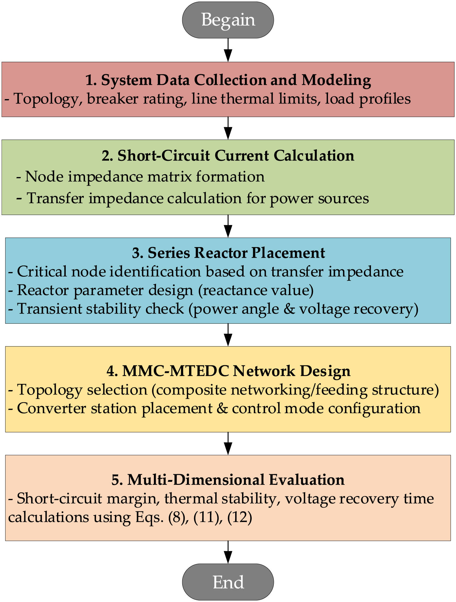
Figure 5: Flowchart of the proposed methodology
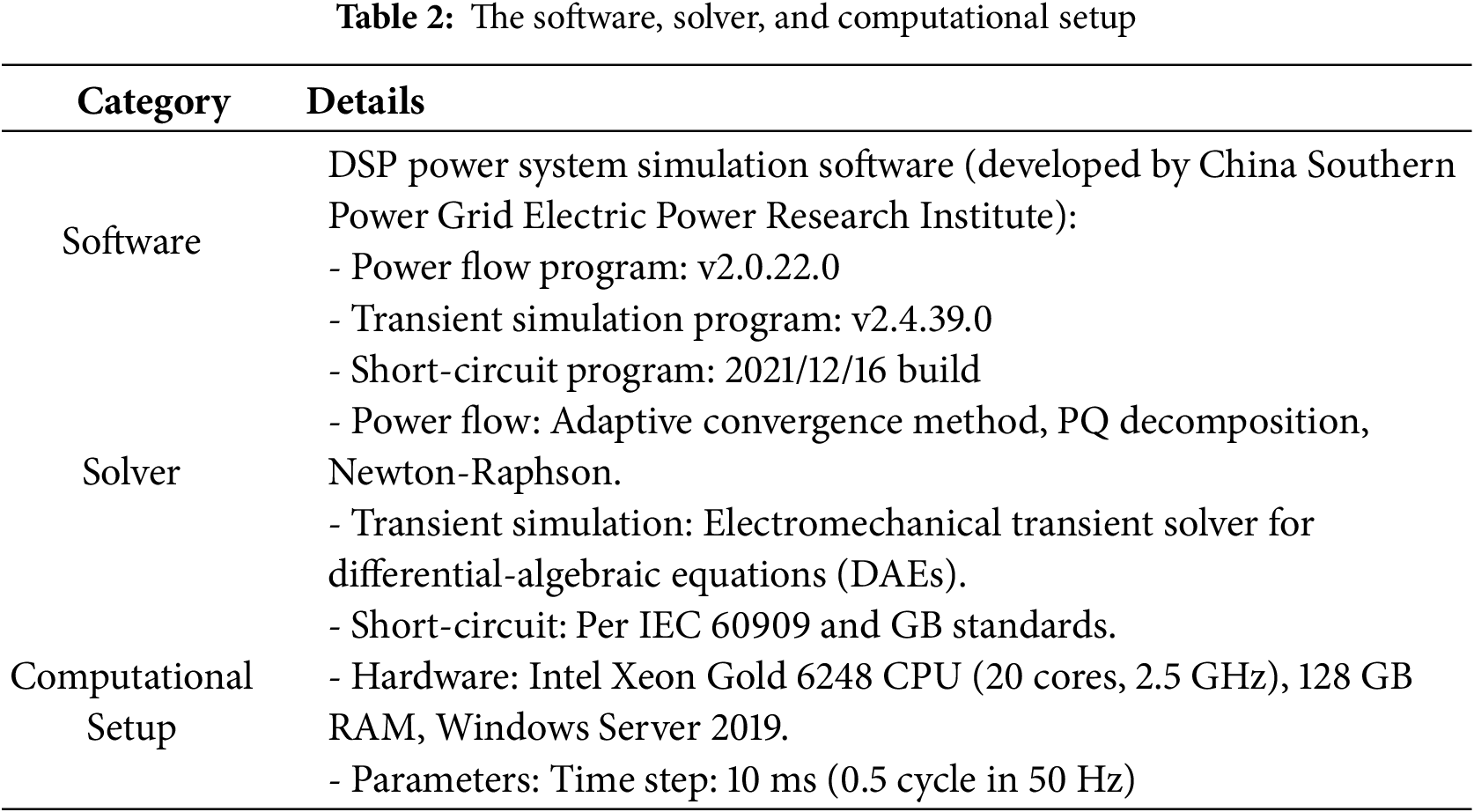
The simulation study, conducted using the DSP power system analysis software independently developed by the China Southern Power Grid Electric Power Research Institute, implements a MMC-MTEDC system within Shenzhen’s 2040 urban grid planning framework, shown in Fig. 6. The software, solver, and computational setup used are specified in Table 2. The core input data for simulations are derived from Shenzhen Power Supply Co., Ltd.’s 2040 summer peak planning data, including:
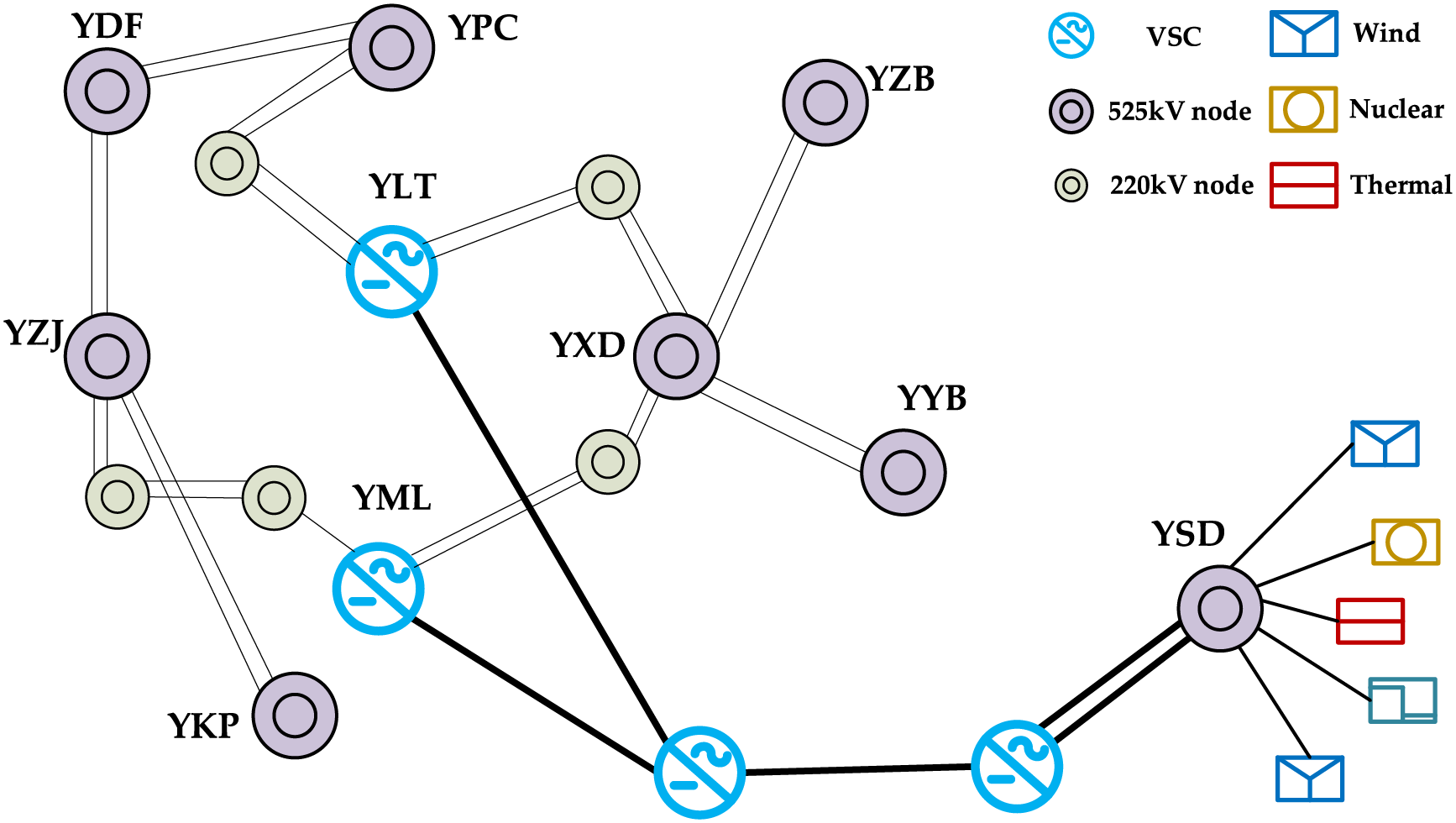
Figure 6: Shenzhen City Grid (Partial) 2040 planning wiring diagram
1. Steady-state power flow files: Containing topological information (e.g., node connections, AC/DC line parameters such as resistance, reactance, and rated capacity), load data (e.g., active/reactive power demands at 220 kV and 525 kV load centers), and generator parameters (e.g., output power, rated voltage, and connection nodes of thermal power plants, nuclear power plants, and pumped storage stations).
2. Transient operation files: Including dynamic characteristics of key components, such as generator excitation systems, power system stabilizers (PSS), and governor parameters; dynamic load models (e.g., induction motor parameters for industrial and commercial loads); and control parameters of MMC-MTEDC systems (e.g., converter station capacity, DC voltage level, and control modes such as fixed active/reactive power or fixed voltage).
5.1 Analysis of Short-Circuit Current Suppression through Series Reactors
5.1.1 Example of Transfer Reactance Calculation
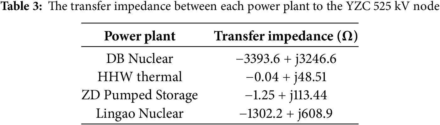
Based on Shenzhen Power Grid’s 2040 summer peak planning data, the transfer impedances from four major power plants in Shenzhen to the 525 kV YZC node were calculated, with results shown in Table 1.
Table 3 indicates that the HHW Power Plant has the closest electrical distance to YZC busbar. Therefore, it is recommended to install series reactors between HHW and YZC 525 kV nodes. Table 4 compares the YZC node’s performance when series reactors (3 Ω) are installed on outgoing lines of four major power plants.
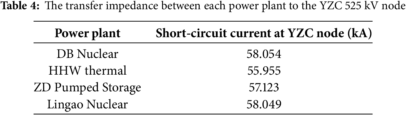
As demonstrated in Table 4, adding series reactors to HHW’s outgoing lines much effectively reduces the short-circuit current at YZC busbar than the other power plants, confirming the effectiveness of placement based on transfer impedance ranking.
As shown in Table 5, the larger the reactor multiplier, the smaller the short-circuit current at YZC 525 kV node. However, the addition of series reactors may impact power angle stability of generation plants and voltage recovery characteristics at target nodes during AC faults. These effects must be evaluated while maintaining transient stability. An N-1 contingency was simulated for the YHH-YZC double-circuit lines, with results for HHW’s power angle stability and YZC 525 kV node’s voltage recovery shown in Figs. 7 and 8, respectively.


Figure 7: Power-angle variation curves of HHW Power plant
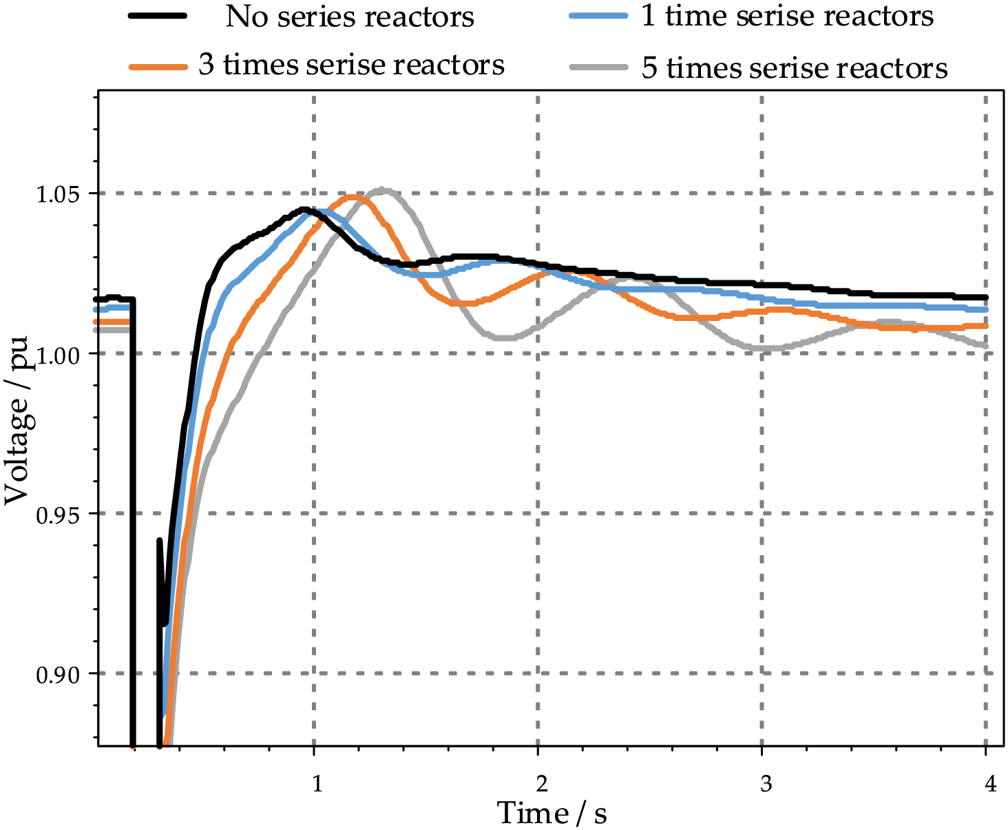
Figure 8: Voltage recovery curves of the YZC 525 kV node
The China Southern Power Grid Security and Stability Calculation and Analysis Guidelines (Q/CSG 1107005-2022) specify the following criteria:
1. Transient Voltage Stability: During post-disturbance transients, bus voltages must recover above 0.80 p.u. within 10 s, and load bus voltages should stabilize above 0.90 p.u. after transients.
2. Transient Rotor Angle Stability: Following disturbances, synchronous generators must maintain stability through the first and second swing periods, with oscillations dampening monotonically while key bus voltages gradually recover.
As evidenced by Figs. 7 and 8, both HHW’s power angle stability and YZC 525 kV node’s voltage stability remain within acceptable limits per these standards.
5.1.2 Analysis of Short-Circuit Current Variations before and after Reactor Installation
Based on the 2040 summer peak data and transfer impedance calculation results, while comprehensively considering multiple factors including power flow conditions, economic feasibility, and practical implementation constraints, the required locations and values of series reactors were determined to ensure a minimum 5% short-circuit current margin across all 525 kV nodes in Shenzhen’s power grid. The specific reactor installations are detailed in Table 6, while Fig. 9 compares the short-circuit current variations at critical nodes before and after reactor installation.
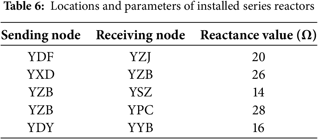
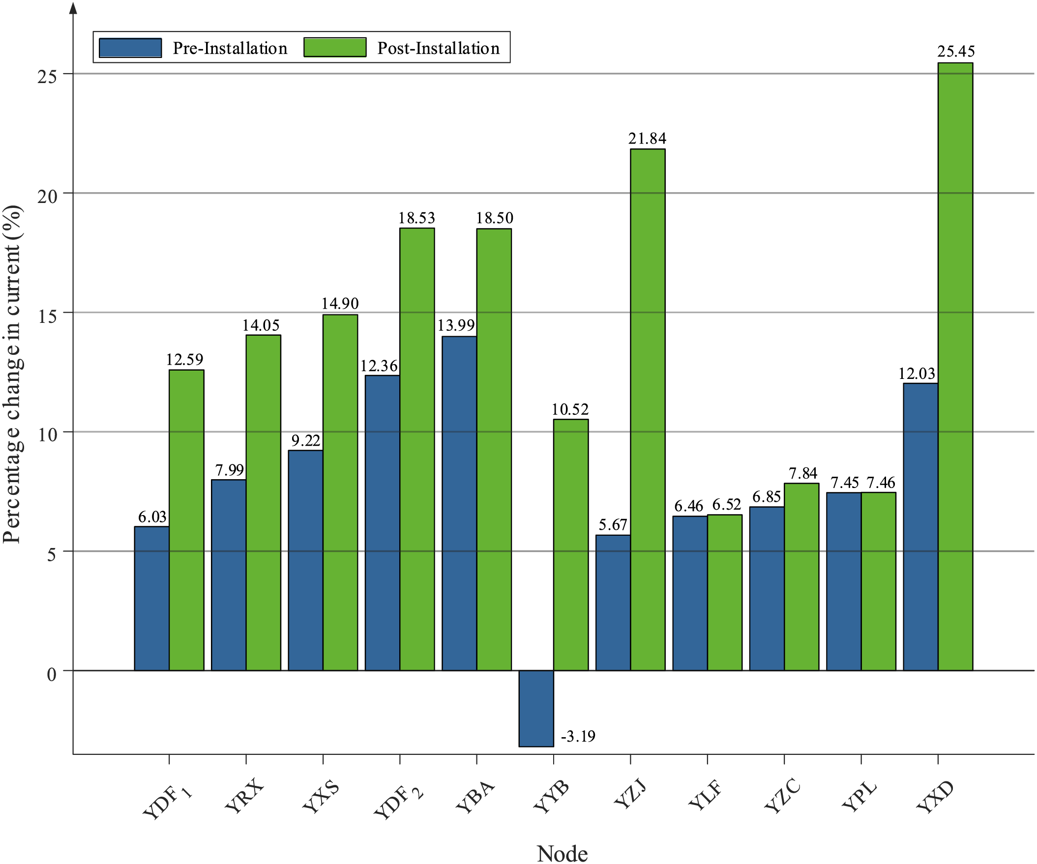
Figure 9: Short-circuit current variations at key nodes
5.2 Impact Analysis of MMC-MTEDC on External Power Integration Capability in Urban Grids
5.2.1 Short-Circuit Current Margin Assessment
Using 2040 summer peak data, Fig. 10 compares short-circuit current levels at critical 525 kV nodes under two integration schemes for the third-channel 5000 MW external power:

Figure 10: Short-circuit current under different integration schemes
Compared to the single-point AC grid integration scheme at the 500 kV network, the MMC-MTEDC grid integration scheme with dual connection points at the 220 kV subnetwork enhances the short-circuit current margin at the 525 kV node of the urban power grid. Specifically, the third access point connected to the 220 kV subnetwork mitigates the impact and demand on the 500 kV network.
5.2.2 Power Evacuation during AC Faults
Based on the 2040 summer peak data with a third-channel capacity of 5000 MW and considering the N-2 contingency of the YLT–YXD double-circuit line, the required power loss (for the point-to-point DC scheme) or flexible DC power margin (for the MMC-MTEDC scheme) to prevent AC line overloading is calculated. The computational process is detailed in Tables 7 and 8, respectively.

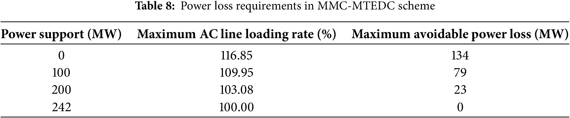
As demonstrated in Table 7, a power curtailment of approximately 134 MW is required in the point-to-point DC scheme to prevent AC transmission line overloading. In contrast, Table 8 reveals that the MMC-MTEDC scheme can completely avoid external power curtailment when maintaining a 242 MW power margin at the YML converter station, enabled through flexible power exchange within the DC grid. This approach significantly enhances the power delivery capability of external generation sources.
5.3 Impact of MMC-MTEDC on Regional Power Exchange Flexibility
5.3.1 Thermal Stability Margin Analysis
Based on the 2040 summer peak data, this study evaluates the thermal stability margin variation when exchanging 5000 MW of external DC power through multiple 220 kV connection points. The analysis focuses on power transfer scenarios between YLT (external power injection node) and YLJ (load center) under two distinct approaches: 1) Conventional AC grid-based power exchange, 2) MMC-MTEDC system (with additional YLJ converter station)
As presented in Table 9, the VSC-HVDC solution demonstrates superior performance in maintaining thermal stability margins compared to traditional AC power transfer. The key findings reveal:

1. The AC-based power exchange reduces thermal margins by 6.87–13.84 percentage points for critical transmission corridors
2. The MMC-MTEDC alternative limits margin reduction to 3.34–6.76 percentage points under identical power transfer conditions
3. For load-center adjacent lines (e.g., YDT-YLJ), the MMC-MTEDC system maintains nearly identical margins to pre-transfer conditions (≤0.07% reduction)
5.3.2 Power Loss in Load Centers during AC Contingencies
For the YLJ subnet (889.7 MW load), Figs. 11 and 12 compare power loss requirements under N-2 AC line outages between Conventional grid operation and MMC-MTEDC with power exchange capability.

Figure 11: Power loss requirements in conventional grid

Figure 12: Power loss mitigation via MMC-MTEDC
Under the condition of no power exchange between MMC-HVDC converter stations, approximately 67.44% load reduction is required to eliminate overloading. When maintaining a 350 MW power margin at the YLT converter station, the MMC-MTEDC system can completely avoid load loss caused by N-2 AC line faults. This demonstrates that utilizing the power exchange capability of MMC-MTEDC can enhance the power supply capacity of load centers and reduce power loss in load centers during AC faults.
5.4 Voltage Stability Optimization in Load Centers Using MMC-MTEDC
Under the 2040 summer peak scenario with an N-1 contingency on the YBJ-YLJ double-circuit line, this study examines voltage recovery characteristics at: 1) YLJ 230 kV node (VSC-HVDC connection point); 2) YDT 230 kV node (remote node). Three operational modes are compared: 1) No MMC-MTEDC; 2) Fixed Q control; 3) Fixed U control.
As shown in Fig. 13, the voltage recovery characteristics at both the YLJ and YDT load nodes under fixed Q control of the MMC-MTEDC show minimal difference compared to operation without MMC-MTEDC, with the only distinction being local reactive power balancing. The fixed U control of the MMC-MTEDC demonstrates more significant improvement in voltage recovery at both load nodes, reducing the recovery time by approximately 19.85% and 17.31%, respectively. This indicates that the fixed U control provides better enhancement of voltage recovery characteristics for the node near the grid connection point compared to the remote node.
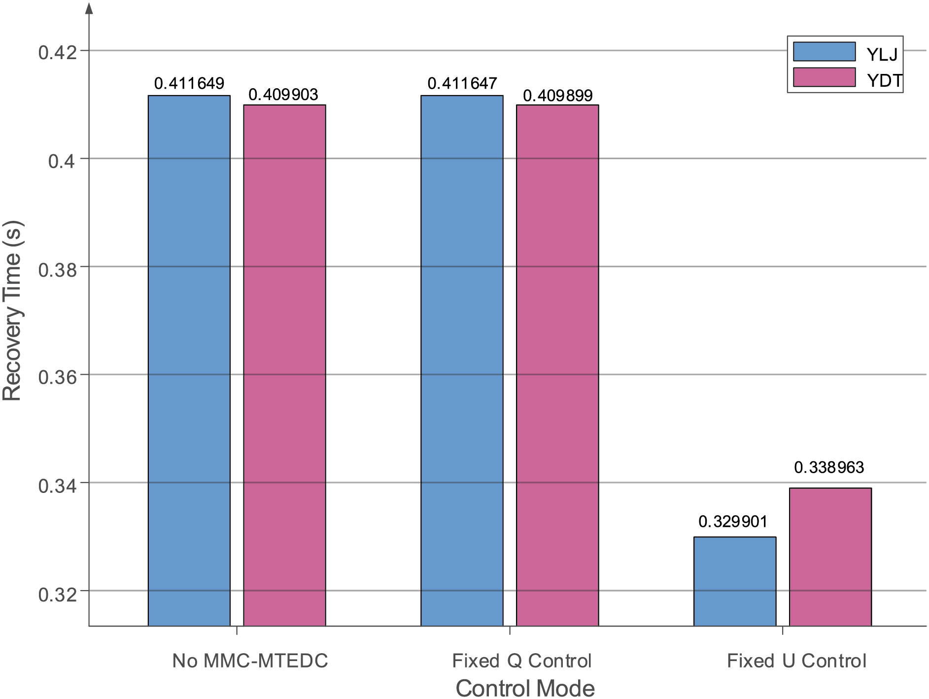
Figure 13: The voltage recovery time of YLJ and YDT node
This paper proposes an urban power grid planning and evaluation methodology based on series reactors and MMC-MTEDC systems. First, the short-circuit current calculation method for large-scale urban power grids is analyzed, introducing the concept of transfer reactance to guide the layout and parameter determination of series reactors. Then, the optimization effects of MMC-MTEDC are discussed in three application scenarios: 1) integration of external power sources, 2) flexible power exchange between grid partitions, and 3) voltage support for load centers, with corresponding evaluation indicators proposed. Finally, simulation analysis is conducted using Shenzhen power grid planning data for 2040. The results demonstrate that this planning approach can effectively suppress short-circuit currents, enhance external power integration capability, improve inter-regional power exchange flexibility, and strengthen voltage stability in load centers.
The proposed methodology specifically addresses the challenges faced by Shenzhen’s mega-city power grid development, including excessive short-circuit currents, external power accommodation, flexible inter-regional power exchange, and voltage stability enhancement in load centers. Notably, the study has limitations. The BPA platform, focused on normal operating frequency analysis, may not fully capture high-frequency transient behaviors during faults, such as rapid DC current rise rates (10 kA/ms) or switching transients in power electronics. For practical implementation, MMC-MTEDC faces critical challenges: In urban grids, land constraints demand lightweight converter stations to reduce footprint, which requires innovative modular design for both hardware and control systems. The control system complexity further varies with real-time grid conditions—load fluctuations, renewable energy integration, and fault scenarios can all alter its improvement effectiveness. Future research will further investigate the common problems and requirements in mega-city power grid development, with potential applications extendable to other mega-city power systems.
Acknowledgement: The authors would like to express their sincere gratitude to China South Power Grid Co., Ltd. for the generous support for this research.
Funding Statement: This research was funded by Shenzhen Power Supply Co., Ltd. Grant number 090000KC24040028.
Author Contributions: Conceptualization, Ying Huang; Data curation, Jing Li; Formal analysis, Ying Huang; Investigation, Guoxing Wu; Methodology, Jing Li; Project administration, Guoxing Wu; Resources, Ming Xiao; Software, Guoteng Wang and Keheng Lou; Validation, Yinghua Xie; Visualization, Ming Xiao; Writing—original draft, Keheng Lou; Writing—review & editing, Yinghua Xie. All authors reviewed the results and approved the final version of the manuscript.
Availability of Data and Materials: The data presented in this study are available on request from the corresponding author due to privacy.
Ethics Approval: Not applicable.
Conflicts of Interest: The authors declare no conflicts of interest to report regarding the present study.
References
1. Wang G, Huang Y, Wang C, Shahidehpour M, Hao Q. Voltage-adaptive strategy for transient stability enhancement of power systems with 100% renewable energy. IEEE Trans Autom Sci Eng. 2024;22:1364–76. doi:10.1109/TASE.2024.3364709. [Google Scholar] [CrossRef]
2. Wang Y, Yu M, Lei X, Wang X, Liu S. Control strategy for voltage profile improvement of VSC-MVDC system in urban power grid. In: 2023 International Conference on Smart Electrical Grid and Renewable Energy (SEGRE); 2023 Jun 16–19; Changsha, China. p. 208–13. doi:10.1109/SEGRE58867.2023.00039. [Google Scholar] [CrossRef]
3. Pan J, Nuqui R, Qi L, Kondabathini A, Gao RG, Jiang H, et al. Urban power grid enhancement and modernization with VSC-HVDC interties. In: 2020 IEEE/PES Transmission and Distribution Conference and Exposition (T&D); 2020 Oct 12–15; Chicago, IL, USA. p. 1–5. doi:10.1109/td39804.2020.9299990. [Google Scholar] [CrossRef]
4. Wang G, Huang Y, Wang C, Shahidehpour M. Multimodal unified control method using the lie derivative and Lyapunov theory for enhancing the dynamic stability of power systems with 100% renewable energy. IEEE Trans Autom Sci Eng. 2024;22:3182–95. doi:10.1109/TASE.2024.3390754. [Google Scholar] [CrossRef]
5. Belhaouane MM, Ayari M, Guillaud X, Braiek NB. Robust control design of MMC-HVDC systems using multivariable optimal guaranteed cost approach. IEEE Trans Ind Appl. 2019;55(3):2952–63. doi:10.1109/TIA.2019.2900606. [Google Scholar] [CrossRef]
6. Gnana Thilaka C, Mary Linda M. Harmonics mitigation using MMC based UPFC and particle swarm optimization. Intell Autom Soft Comput. 2023;35(3):3429–45. doi:10.32604/iasc.2023.024028. [Google Scholar] [CrossRef]
7. Zhang H, Zhang W, Jiao B. Analysis of inter-turn short circuit characteristics in the windings of dry-type air-core series and shunt reactors. In: 2024 IEEE 7th International Conference on Automation, Electronics and Electrical Engineering (AUTEEE); 2024 Dec 27–29; Shenyang, China. p. 452–6. doi:10.1109/AUTEEE62881.2024.10869733. [Google Scholar] [CrossRef]
8. Bex L, Liu X, Leterme W, Judge P, Hertem DV. Voltage support and electrical stresses in MMC-HVDC systems during AC faults. In: 2023 IEEE PES Innovative Smart Grid Technologies Europe (ISGT EUROPE); 2023 Oct 23–26; Grenoble, France. p. 1–5. doi:10.1109/ISGTEUROPE56780.2023.10407419. [Google Scholar] [CrossRef]
9. Tang W, Mao T, He S, Zhou B, Chen J, Zhao W, et al. Virtual power plant cloud-management-edge fusion architecture for large-scale application of various types of flexible resources in urban power grids. In: 2024 4th International Signal Processing, Communications and Engineering Management Conference (ISPCEM); 2024 Nov 28–30; Montreal, QC, Canada. p. 320–5. doi:10.1109/ISPCEM64498.2024.00060. [Google Scholar] [CrossRef]
10. Lyu J, Cai X, Molinas M. Frequency domain stability analysis of MMC-based HVdc for wind farm integration. IEEE J Emerg Sel Top Power Electron. 2016;4(1):141–51. doi:10.1109/jestpe.2015.2498182. [Google Scholar] [CrossRef]
11. Li X, Xu Z, Zhang Z. Application of MMC with embedded energy storage for overvoltage suppression and fault ride-through improvement in series LCC-MMC hybrid HVDC system. J Mod Power Syst Clean Energy. 2023;11(3):1001–13. doi:10.35833/mpce.2021.000703. [Google Scholar] [CrossRef]
12. Li Y, Jones EA, Wang F. The impact of voltage-balancing control on switching frequency of the modular multilevel converter. IEEE Trans Power Electron. 2015;31(4):2829–39. doi:10.1109/TPEL.2015.2448713. [Google Scholar] [CrossRef]
13. Ji S, Huang X, Palmer J, Wang F, Tolbert LM. Modular multilevel converter (MMC) modeling considering submodule voltage sensor noise. IEEE Trans Power Electron. 2020;36(2):1215–9. doi:10.1109/TPEL.2020.3008524. [Google Scholar] [CrossRef]
14. Wang Y, Zhang Z, Xu Y, Gao Y, Xu L, Xu X. Topology and control of an arm multiplexing MMC with full-range voltage regulation. IEEE Trans Power Electron. 2024;39(12):16135–51. doi:10.1109/TPEL.2024.3424402. [Google Scholar] [CrossRef]
15. Xin Y, Wang T, Yang Y, Wang W, Feng Z, Dong Q. A short-circuit current calculation method based on discrete model for VSC-HVDC grids. In: 2019 4th IEEE Workshop on the Electronic Grid (eGRID); 2019 Nov 11–14; Xiamen, China. p. 1–6. doi:10.1109/egrid48402.2019.9092642. [Google Scholar] [CrossRef]
16. Wang W, Shao Q, Wang S, Zhao Y, Ye Y, Li D, et al. Partitioning calculation method of short-circuit current for high proportion DG access to distribution network. Energy Eng. 2024;121(9):2569–84. doi:10.32604/ee.2024.051409. [Google Scholar] [CrossRef]
17. IEEE. IEEE recommended practice for conducting short-circuit studies and analysis of industrial and commercial power systems [Internet]. 2019 [cited 2025 Jul 28]. Available from: https://ieeexplore.ieee.org/stamp/stamp.jsp?tp=&arnumber=8672198&tag=1. [Google Scholar]
18. Wang G, Huang Y, Xu Z, Li F, Liu R. Dynamic frequency trajectory prediction assisted frequency response method for lightweight MTDC systems. IEEE Trans Power Deliv. 2025;40(3):1365–78. doi:10.1109/TPWRD.2025.3545432. [Google Scholar] [CrossRef]
19. Ye H, Chen W, Wu H. Analysis of the existence of stable equilibrium points in the WPP-MMC system under symmetrical ac fault. IEEE Trans Sustain Energy. 2025;16(1):95–106. doi:10.1109/tste.2024.3433611. [Google Scholar] [CrossRef]
20. Kan P, Zheng H, Yuan X, Zhou L, Zou X, Xiong W. Large-signal stability analysis of MMC-HVDC system under grid voltage dips based on mixed potential theory. In: 2022 7th International Conference on Power and Renewable Energy (ICPRE); 2022 Sep 23–26; Shanghai, China. p. 40–5. doi:10.1109/ICPRE55555.2022.9960302. [Google Scholar] [CrossRef]
Cite This Article
 Copyright © 2025 The Author(s). Published by Tech Science Press.
This work is licensed under a Creative Commons Attribution 4.0 International License , which permits unrestricted use, distribution, and reproduction in any medium, provided the original work is properly cited.
 Downloads
 Citation Tools