
 Submit a Paper
 Propose a Special lssue
 Open Access
ARTICLE
Enhancement of Frequency Regulation in AC-Excited Adjustable-Speed Pumped Storage Units during Pumping Operations
1 Construction and Management Branch of China Southern Power Grid Energy Storage Co., Ltd., Guangzhou, 510000, China
2 NR Electric Co., Ltd., Nanjing, 210000, China
3 Hohai University, Nanjing, 210000, China
* Corresponding Author: Xianglin Zhang. Email:
(This article belongs to the Special Issue: Advances in Renewable Energy Systems: Integrating Machine Learning for Enhanced Efficiency and Optimization)
Energy Engineering 2025, 122(12), 5175-5197. https://doi.org/10.32604/ee.2025.068692
Received 04 June 2025; Accepted 11 August 2025; Issue published 27 November 2025
 View Full Text
 Download PDF
Abstract
The integration of large-scale renewable energy introduces frequency instability challenges due to inherent intermittency. While doubly-fed pumped storage units (DFPSUs) offer frequency regulation potential in pumping mode, conventional strategies fail to address hydraulic-mechanical coupling dynamics and operational constraints, limiting their effectiveness. This paper presents an innovative primary frequency control strategy for double-fed pumped storage units (DFPSUs) operating in pumping mode, integrating an adaptive parameter calculation method. This method is constrained by operational speed and power limits, addressing key performance factors. A dynamic model that incorporates the reversible pump-turbine characteristics is developed to translate frequency deviations into coordinated adjustments in speed and power during pumping operations. The research thoroughly analyzes the influence of control parameters on the frequency response dynamics. Additionally, the paper introduces a deep reinforcement learning (DRL)-based optimization framework, which enables real-time tuning of control parameters in response to changing rotor speed and frequency states. This method strategically manages the utilization of kinetic energy while ensuring compliance with operational safety constraints. The effectiveness of the proposed strategy is validated through simulation studies conducted on a four-machine, two-area DFPSU system. These studies demonstrate the strategy’s potential for improving frequency regulation performance under a variety of operating conditions, highlighting its effectiveness in optimizing energy storage and frequency control in power grids.Keywords
The scale of grid-connected operation of wind, light and other renewable clean energy sources is gradually expanding. However, these renewable energy sources are characterized by randomness, volatility and intermittency, which will lead to deterioration of the frequency characteristics of the power grid. Pumped storage is one of the most important means to solve the grid frequency problem. Conventional pumped storage units do not participate in grid frequency regulation because the power cannot be continuously adjusted under pumping condition [1].
The novel pumped storage power station, founded upon the double-fed pumped storage unit (DFPSU), boasts the capability to operate at variable speeds within a designated range. This advancement not only surmounts the limitations of conventional pumped storage units, such as the suboptimal efficiency stemming from the fixed motor speed and the incapacity to modulate power during pumping, but also endows the station with augmented power regulation flexibility. It has been demonstrated that through variable-speed operation, the DFPSU possesses augmented frequency regulation capacity and a measure of frequency regulation potential, thereby offering a viable solution to address the mounting challenges posed by grid frequency regulation. Nevertheless, the conventional control strategy employed in DFPSU results in the decoupling of unit speed from grid frequency, thereby hindering the unit’s capacity to autonomously contribute to grid frequency adjustment. Reference [2] introduces an improved virtual inertia control strategy, addressing the negative damping effects in later frequency regulation stages by replacing the
Recent research on DFPSU has primarily focused on modeling and power decoupling control. Study [3] has developed models for the electrical and hydraulic components of DFPSUs, analysing both steady-state and transient behaviours. Additionally, reference [4] proposes rapid power response strategies based on unit operating characteristics. Given the similarities between doubly-fed induction generators and DFPSUs during power generation, much of the current frequency regulation research for DFPSUs follows approaches from doubly-fed wind turbines, such as droop control and virtual inertia control to quickly convert frequency deviations into power adjustments.
While simulation-based validations in prior research confirm the feasibility of DFPSUs’ autonomous participation in grid frequency regulation across both generating and pumping modes, these investigations uniformly assume a generation-dominant control paradigm. Research on the integrated electromechanical control between reversible pump-turbine units and AC excitation machines (ACEM) remains relatively scarce. Existing studies predominantly focus on the stand-alone control of the ACEM itself, with most applications centered in the wind power generation field. For instance, Reference [5] proposed a vector control method based on rotor flux orientation to investigate power decoupling control within the machine. Reference [6] examined the steady-state characteristics and starting performance of the machine under various converter topologies. Notably, they omit critical analysis of the dynamic hydraulic-mechanical coupling effects inherent to reversible pump-turbine operations. The literature [7] has established a DFPSU participation in the frequency control in the pumping condition that accounts for the characteristics of the water pump turbine. Nevertheless, due to the variability in DFPSU operation, the application of fixed frequency parameters is inadequate for ensuring the stability of the hydroelectric turbine under varying conditions. Moreover, it hinders the recovery of the frequency during the frequency adjustment phase. In the domain of Doubly fed Induction Generator, literature [8] explores methodologies for enhancing the adaptability of frequency control strategies in the presence of variable wind speeds and disturbances. This research leads to the development of a variable-parameter frequency control strategy. Recent work by Gulzar et al. [9] proposes an adaptive tilt fractional-order PID (ATFOPID) controller optimized via tunicate search algorithm to enhance transient stability in renewable-integrated hybrid power systems. However, it is noteworthy that this particular research area is seldom addressed in the context of DFPSU.
This paper first develops a mathematical model for the DFPSU, including the pump-turbine, along with a corresponding control strategy for pumping mode. Subsequently, a frequency control strategy is proposed that converts frequency deviations into additional speed and active power commands under pumping conditions. This strategy leverages the coordination between the inverter and the pump-turbine to enhance the DFPSU’s flexible power regulation capabilities. Furthermore, an analysis is conducted on the impact of DFPSU operating states and frequency control parameters. With the goal of maximizing rotor kinetic energy release while imposing constraints on speed and power, an adaptive parameter optimization method based on Deep Reinforcement Learning (DRL) is introduced. This method aims to reduce the maximum frequency deviation and shorten the frequency recovery time, thereby improving the overall system frequency stability. Finally, the effectiveness of the proposed frequency control strategy is validated through a comparative analysis of the frequency dynamic response in a four-machine, two-area system model, in which DFPSU is integrated, and compared with traditional frequency control methods.
2 Math Model DFPSU and Control Strategies
As is shown in Fig. 1, the DFPSU system is predominantly constituted by a reversible pump/turbine and its regulating system, the DFIM, a back-to-back converter, and the associated control modules. The coordination of the hydraulic, mechanical, and electrical components under varying operational conditions facilitates the regulation of speed and the decoupling of active and reactive power.
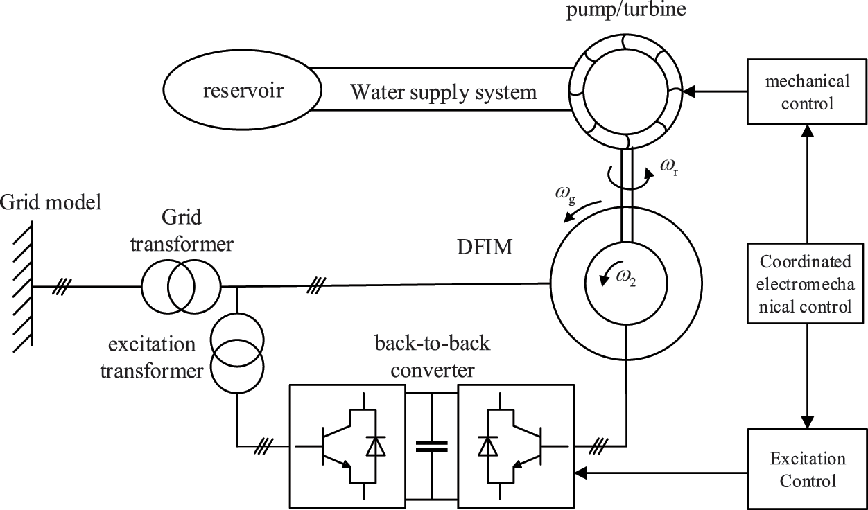
Figure 1: Structure of DFPSU unit
DFPSU employs a dual-feedback configuration, enabling the selection of an appropriate magnetic control strategy to achieve rapid and precise regulation of various physical quantities. In circumstances where the stator and rotor are both equipped with permanent magnet synchronous motors, the dual-feedback electrical machine’s mathematical model is expressed as follows:
where subscripts
2.2 Mathematical Model of Water Supply System
The water supply system consists of a water cave, a pressure regulating chamber and a pressure pipe. As the water flow through the pipe will cause a series of energy losses including friction loss in the pipe and friction loss in the valves and accessories, the required head of the device not only includes the static head determined by the difference in water level between the upper and lower tanks, but also the additional head required to compensate for this loss [7]. The characteristics of the pipe can be obtained as shown in Eq. (3).
where
Mathematical models of water delivery systems can be divided into rigid and elastic models, depending on whether the elasticity of water hammer is taken into account. When the elasticity of the water flow and the pipe wall is taken into account, an elastic dynamic model of the water delivery system is obtained as shown in Eq. (4). Further expansion of the hyperbolic function in the equation according to an infinite series allows the dynamic model to be selected according to the requirements of the application. In general, expansion of the second term is sufficient to meet the requirements of most power system stability studies.
where
The theory of rigid water hammer posits that, for a relatively short water supply pipeline (<800 m), the water hammer pressure can be instantaneously transmitted to the entire water supply pipeline, i.e.,
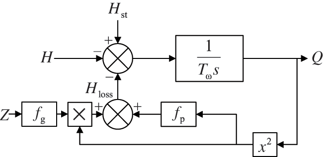
Figure 2: Rigid dynamic model of water delivery system
When the pump-turbine is switched to pump mode, the unit is near rated operation, the guide vane opening is large, and there is serious crossing of the full characteristic curve in the corresponding area. At this time, the unit’s flow rate is basically not affected by the guide vane opening, and its mechanical power and efficiency are closely related to the speed. The adjustment of the input active power is mainly achieved by controlling the speed rather than the guide vane opening.
In this mode, the pump’s operating characteristics are characterized by fitting the full characteristic curve of the pump turbine. In this section, the head-flow (
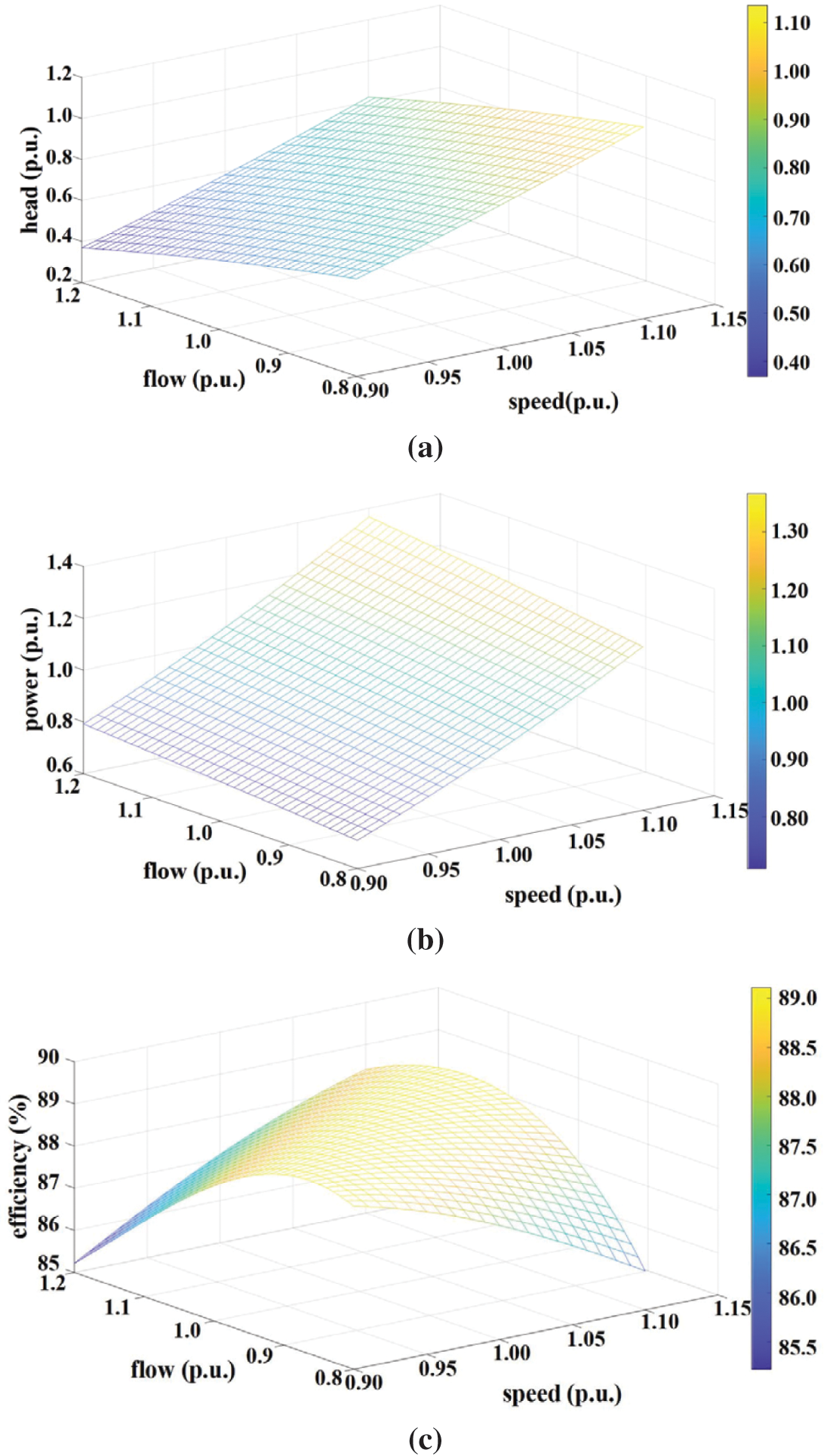
Figure 3: Operating characteristic curves of pump: (a)
In consideration of the aforementioned points, this section synthesizes the rigid water hammer model of the water supply system with the power and head expressions, respectively, to derive the pump-turbine model in the state of the pump (see Fig. 4).
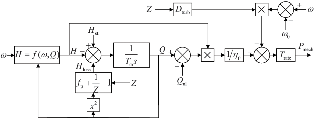
Figure 4: Model of reversible pump/turbine in pump mode
2.3 Speed Priority Control Strategy
When the DFPSU is in pumping operation, active power control can be achieved by adjusting the speed of the unit, and the primary objective is to require the speed to accurately and quickly track the optimal value. To this end, the speed priority control strategy shown in Fig. 5 is selected under pumping conditions. First, the active power command
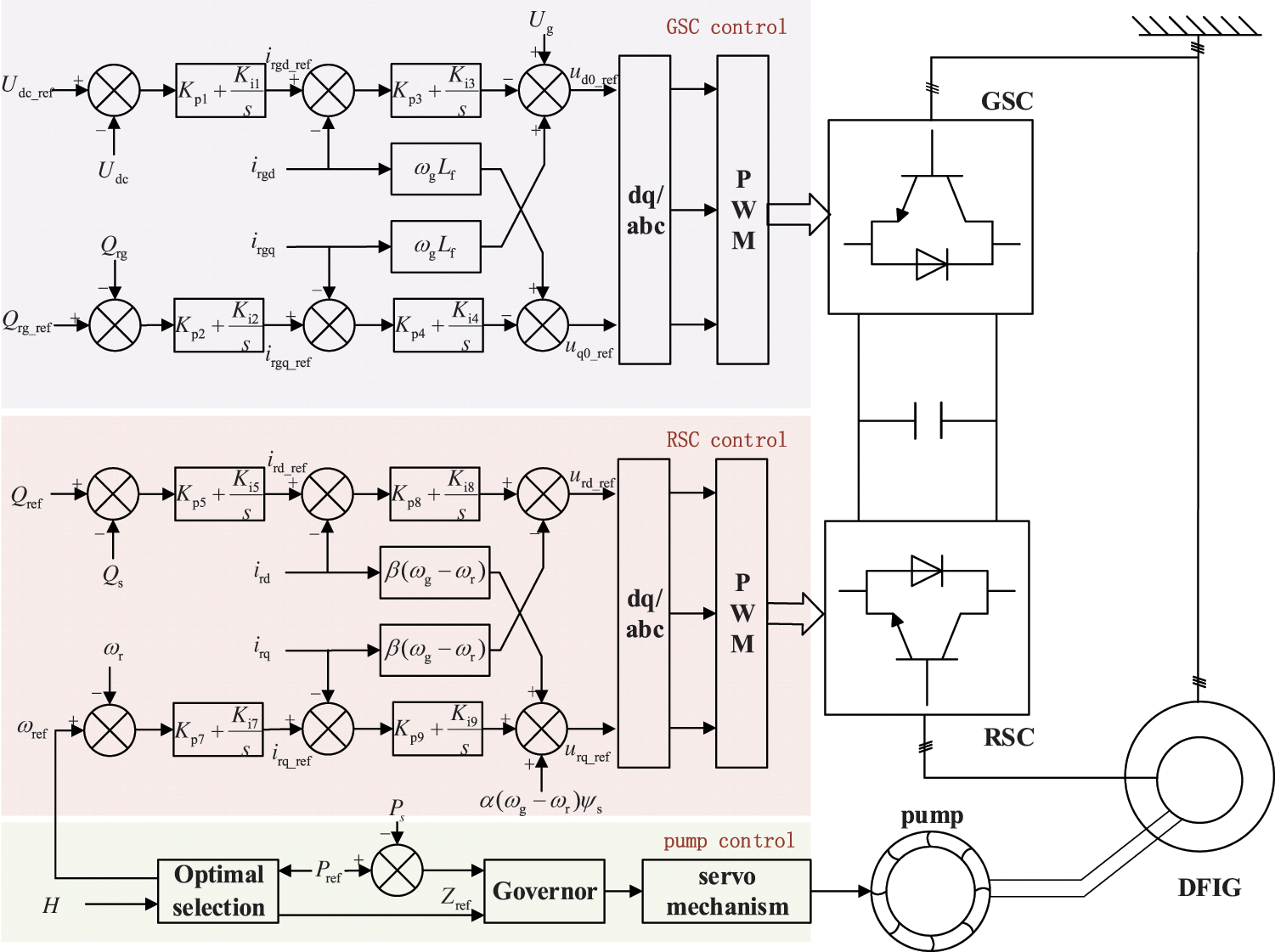
Figure 5: Control structure of speed priority control strategy
3 DFPSU Frequency Control Strategy
3.1 Additional Frequency Control Module
In the event that the DFPSU is engaged in pumping mode, the unit employs a speed priority control strategy, whereby the response speed of the active power is directly modified by adjusting the opening of the pump guide vane. However, the response is characterized by its relatively slow nature. Concurrently, the time scale of primary frequency regulation is relatively brief, thereby classifying this process as a transient phenomenon within electromechanical systems. During this process, the action of the pump efficiency optimization module is not taken into account, and the corresponding control cannot be automatically completed. Consequently, if the traditional strategy consistent with the power generation operating condition is employed at this time, it becomes challenging to ensure the speed and effectiveness of the frequency regulation response [10]. To address these challenges, this paper proposes a novel frequency control method, as illustrated in Fig. 6. This method converts the frequency deviation (
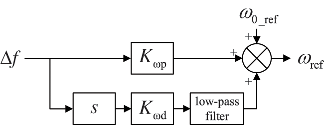
Figure 6: Frequency response model of DFPSU
3.2 Low-Order System Frequency Response Model
The system frequency response (SFR) model is a significant method for analyzing the dynamic response of a power system to frequency fluctuations [11]. The primary focus of this model is the study of frequency fluctuations in the context of electrical processes, while simplifying other time-scale processes. This approach enables the effective reduction of other time-scale processes, while maintaining the key capabilities of the power system. The frequency response model is a significant method for analyzing the dynamic response of an electrical system to frequency changes. It focuses on the dynamic changes in the electrical system itself, while simplifying other time-scale processes. This approach can effectively reduce the dynamic response of an electrical system, while preserving its key characteristics.
The frequency response model consists of various frequency control models and the model of constant load power generation. The frequency control model in this paper is a model of frequency control and load-flow, which is used to describe the dynamic changes in power generation caused by frequency deviations.
In order to reduce the order of the DFPSU unit frequency control model, the unit’s change process on a time scale other than the electromechanical transient is simplified, focusing on the rapid regulation of the converter on the unit’s active power. The following assumptions are made: the change process of the internal magnetic flux of the motor is ignored, and it is considered to remain unchanged during frequency regulation; the minute-level regulation process at the pump-turbine is ignored, that is, it is considered that the efficiency optimization module does not operate during frequency regulation, and the influence of the pump-turbine on the unit’s power regulation is not counted.
The rotor-side converter constitutes the core component of the inverter, serving to achieve precise and expeditious tracking of the command value. Within the double-loop control structure of the inverter, the current inner loop reflects the change of the rotor current, and its response time is in the millisecond range. It can be regarded as instantaneous in the time scale of the electromechanical transient of frequency regulation [12], thereby simplifying the inverter to Gc(s).
Assuming that the dynamic change in the magnetic flux of the motor stator is negligible, it can be deduced that the active power and electromagnetic torque of the generator are proportional to the q-axis component of the rotor current during frequency control. Consequently, a relationship can be established between the change in the converter control command
As demonstrated above, the model of a water pump in pumping mode consists of
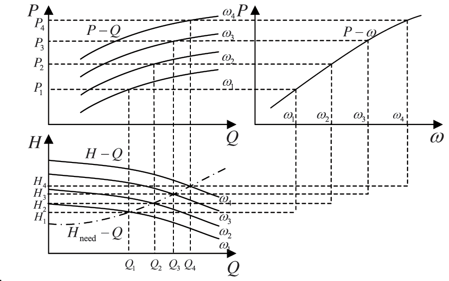
Figure 7: Schematic of operating characteristics of pump
The DFPSU employs a speed regulation mode that utilizes a constant vane opening near the rated operating point under pumping conditions. Consequently, the P – Q curve can be mapped to a power-speed (
where ki is the fitting coefficient, i = 0, 1, 2, 3.
The linearization of Eq. (11) at the steady state with rotational speed
In conjunction with the previously mentioned frequency control module, the frequency control model of the DFPSU is illustrated in Fig. 8. The figure elucidates the time constants
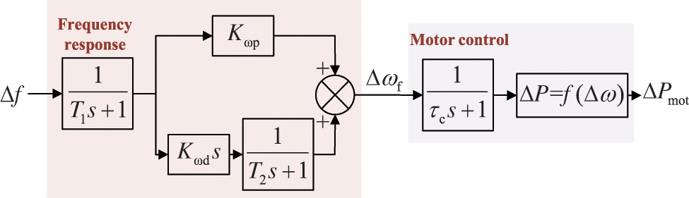
Figure 8: Frequency control models of DFPSU [11]
As asserted by literature [13], the generator-load model of the power system is determined by the sum of the outputs of various types of frequency regulation units, designated here as
where
In the SFR model,
3.2.3 General System Frequency Response Model
Based on the above analysis, the unit is connected to a four-machine, two-zone model, and an improved SFR model containing a doubly-fed induction generator unit is proposed as shown in Fig. 9. In order to depict the dynamic process of frequency control of thermal power units and hydroelectric power units, typical parameters are taken for thermal units, and the classical small-signal model is used for hydraulic turbines. In the case of hydro units, the governor is appropriately compensated for inadequate gain and phase margin of the system.
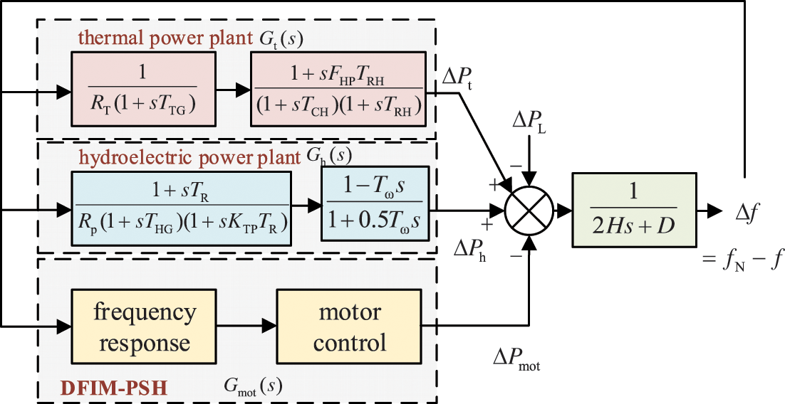
Figure 9: SFR model of system with DFPSU
Based on Fig. 9, we can derive the expression for the calculation of the grid
where subscript
4.1 Influence of
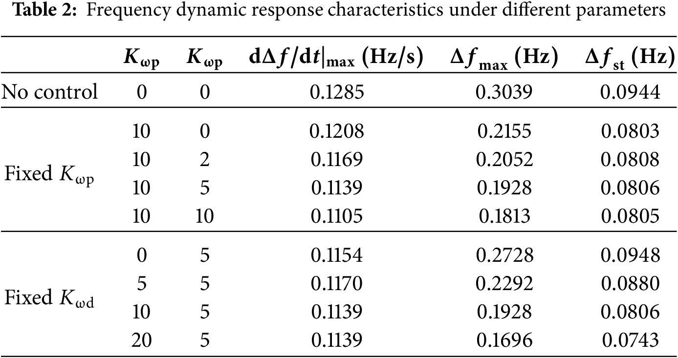
The frequency dynamic response index, which is a measurement of the effect of frequency control, principally includes frequency deviation, the rate of change (
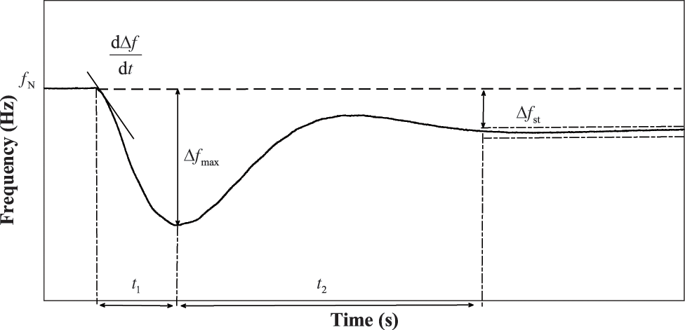
Figure 10: Response curve of primary frequency regulation
The rate of frequency change, or
Based on Fig. 8, ignoring the time constants of the frequency detection module and the low-pass filter in the DFPSU unit, the primary frequency control output under different operating conditions can be obtained as follows:
Considering that only DFPSU units are involved in frequency control in the system and ignoring their millisecond converter response time, the frequency response model shown in Fig. 9 can be rewritten as follows:
It is hypothesized that the system is subjected to a disturbance of amplitude
Pursuant to the initial value theorem, calculate the derivative of the function
In accordance with the final value theorem, the steady-state frequency deviation, designated as
As demonstrated in Eqs. (20) and (21), the differential control channel of the constructed frequency control module is equivalent to increasing the equivalent inertia of the system. This can rapidly suppress frequency changes, i.e., reduce
In order to verify the rationality of the aforementioned inference, this study will substitute different values of
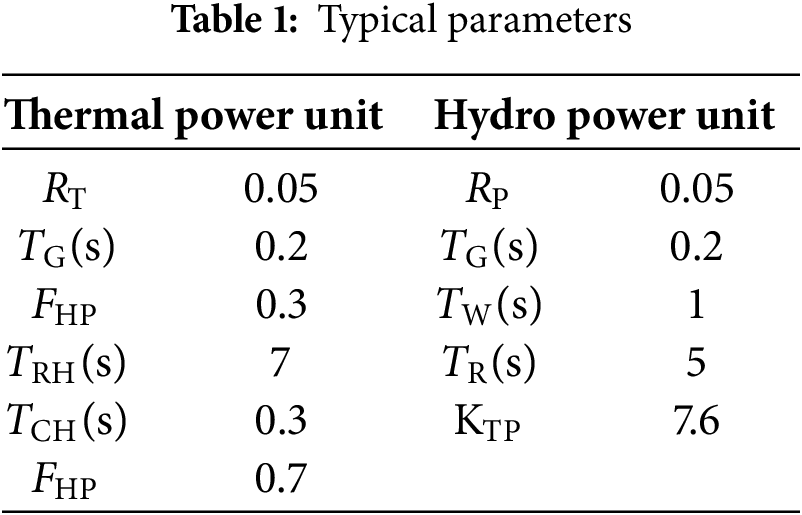
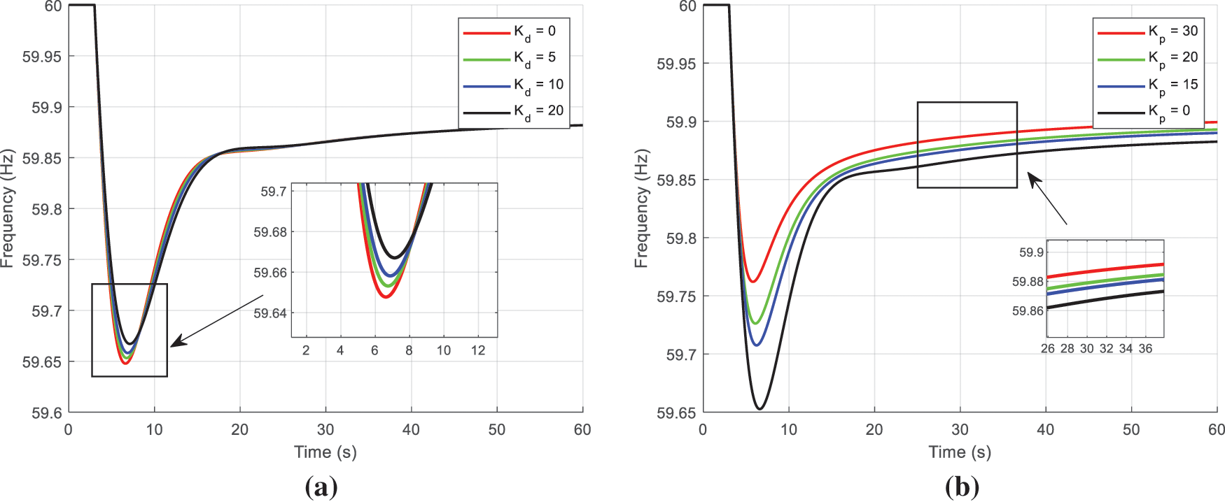
Figure 11: Comparison of response curves under different parameters: (a) response curves under different
4.2 Extremum Determination for Parameters
The root locus of each frequency control parameter is plotted according to Eq. (15). In the figure, the damping ratio is denoted by
As illustrated in Fig. 12a, when the fixed
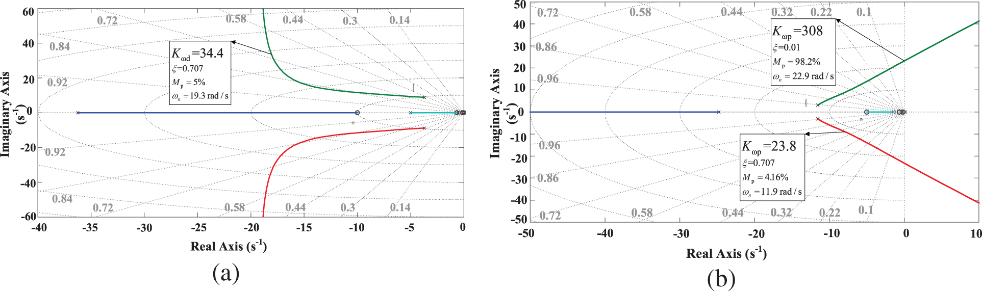
Figure 12: Zero-pole trajectory of frequency deviation transfer function: (a)
4.3 DRL-Based Adaptive Parameter Optimization
4.3.1 Introduction to Algorithms
Deep reinforcement learning (DRL) is a type of learning based on the state of the environment. The agent engages with the environment to acquire state information and perpetually refines its strategy to optimize the anticipated reward [14]. This approach to learning from past experiences has proven effective in circumventing the issue of overparameterization and the subsequent challenge of ascertaining the present control method. In this paper, the current well-performing twin delayed deep deterministic policy gradient (TD3) algorithm [15] is employed to address the issue of energy storage participation in primary frequency regulation. TD3 employs the Actor-Critic framework, which facilitates the generation of continuous actions and represents an enhancement over the deep deterministic policy gradient (DDPG) algorithm [16].
4.3.2 Design of Frequency Control Agents
The issue of integrating DFPSU into primary frequency control of the power grid is represented by a Markov decision process (MDP), which necessitates the delineation of a quintuple
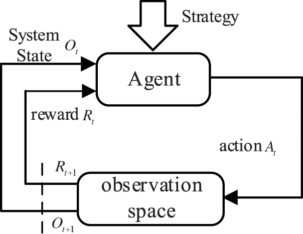
Figure 13: The process of solving problem and interaction in DRL algorithm
The state space of an agent is the agent’s observational information about the current state of the environment. This paper includes three parts in the observation: the current frequency deviation of the power grid, the change in frequency deviation, and the current speed state of the generator.
The control quantities are defined as the Frequency Control parameters
The reward function is the sole criterion by which the agent assesses the quality of an action, and its design is intimately associated with the evaluation index. To this end, the reward function in this paper is composed of two constituent parts: an evaluation index and a punishment index.
The evaluation index is composed of the weighted frequency control effect evaluation index and the unit release kinetic energy index. The traditional frequency evaluation index is the difference between the current frequency
The alteration in the unit’s kinetic energy is associated with the initial and current rotational speeds of the unit during frequency control.
where the quantity of poles of the generator set is denoted by
In summary, the formula for the evaluation index in the reward function is as follows:
where
This method penalizes the agent for frequently changing its action direction in commands, with the objective of guiding the agent to issue smoother commands. Specifically, a penalty is imposed when the agent has changed direction twice in the last three commands. This penalty significantly exceeds the reward received from this mode of operation.
where
In summary, the agent’s reward function is
In order to ensure the safe operation of the unit, the following restrictions on unit power and speed are hereby proposed, based on actual operating conditions:
The proposed control strategy robustly accommodates parametric variations—such as seasonal load-response shifts and renewable generation fluctuations—through real-time state feedback mechanisms. However, when confronting structural changes including grid topology reconfigurations or unit outages, which fundamentally alter the system frequency response (SFR) transfer function and inertia constant H, a transfer learning-based rapid retraining protocol is employed: Pretrained networks are adaptively fine-tuned using topology-specific operational data, achieving convergence within 50 training episodes.
4.4 Analysis of Optimization Results
After optimizing the unit under several typical operating conditions, the optimal frequency control parameters can be obtained for each scenario. In this example, a 10% load increase is considered. Initially, the Support Vector Regression (SVR) method is employed to model the data, thereby addressing issues such as noise or outliers. The Support Vector Regression (SVR) method has emerged as a prominent machine learning fitting technique in recent years, adeptly capturing the nonlinear characteristics of data and yielding more precise fitting outcomes. The objective of the fitting process is to approximate the overall trend of the data through the SVR model to obtain a more accurate fitting curve. Subsequently, the data is smoothed using cubic spline interpolation to further optimize the smoothness and continuity of the curve. The efficacy of cubic spline interpolation in generating a smooth curve with continuous first and second derivatives between data points is well-documented. This approach effectively reduces oscillation during the fitting process, thereby maintaining the overall trend of the data.
The specific training process is illustrated in Fig. 14. Agent achieved substantial convergence after approximately 50 training episodes, attaining a final real-time reward value of −23.6822. This demonstrates strong online learning capability, indicating favorable convergence characteristics of the agent system. Consequently, it enables reliable simulation of frequency stabilization under disturbance scenarios across diverse DFPSU operating conditions.
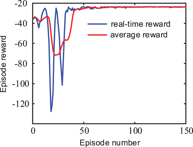
Figure 14: Training process
Taking the frequency drop scenario as an optimization example, the resulting curve is shown in Fig. 15. Combining the frequency control characteristics of the generator set during a frequency drop, i.e., the generator set will reduce the speed to release the rotor kinetic energy, and increase the active power output or reduce the active power input to provide stable power support, it is not difficult to summarize the law of change of the final frequency control parameters: when the generator set is in the low speed stage, the value of the frequency control parameters is relatively small, so as to avoid the generator set from causing a serious speed drop due to excessive release of the rotor kinetic energy. As the speed increases, the frequency control parameter gradually increases to make full use of the rotor kinetic energy contained in the unit. However, when the speed increases to a certain value, the input/output active power of the corresponding unit will also increase to a higher level. At this time, in order to ensure that the unit does not overreact and the power exceeds the allowable range, the frequency control parameter is reduced accordingly. Since the principle of changing the limit frequency control parameter for the frequency increase scenario is the same as that for the frequency decrease scenario, it will not be presented here.
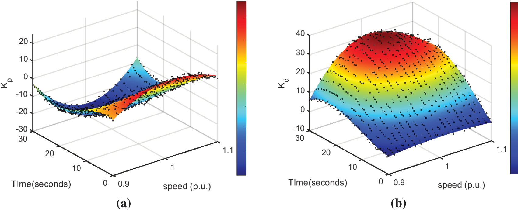
Figure 15: Optimal frequency control parameter curve: (a) Optimal
The differential control coefficient
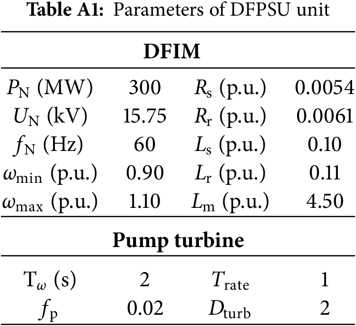
To evaluate the performance of the DFPSU frequency control module developed in this paper and to demonstrate the superiority of the proposed adaptive variable-parameter frequency control strategy, this section presents a simulation of the DFPSU model integrated into a four-machine two-area system, as depicted in Fig. A1 and Table A1, using the PSCAD/EMTDC simulation platform. The frequency dynamics of the system are analyzed under a sudden step load increase, with comparisons drawn between different control methods and parameter settings. The corresponding dynamic response characteristics are then assessed and compared to validate the effectiveness of the proposed control approach.
5.1 Simulation Verification of Additional Frequency Control Module
The initial active power command of the DFPSU is set to −0.8 p.u., and the corresponding optimal speed command is 0.987 p.u. After the unit has been operating stably for 20 s, the load suddenly increases by 10%. The response of the system frequency, active power, and speed of the generator under the control mentioned in this paper, including traditional control, proportional control channel only, differential control channel only, and both channels acting, is shown in Fig. 16. In the context of DFPSU in pumping mode, the speed is identified as the primary control target of the converter. Consequently, the active power of the system is contingent upon the adjustment of the guide vane opening at the pump. Conversely, if the traditional control method, which converts
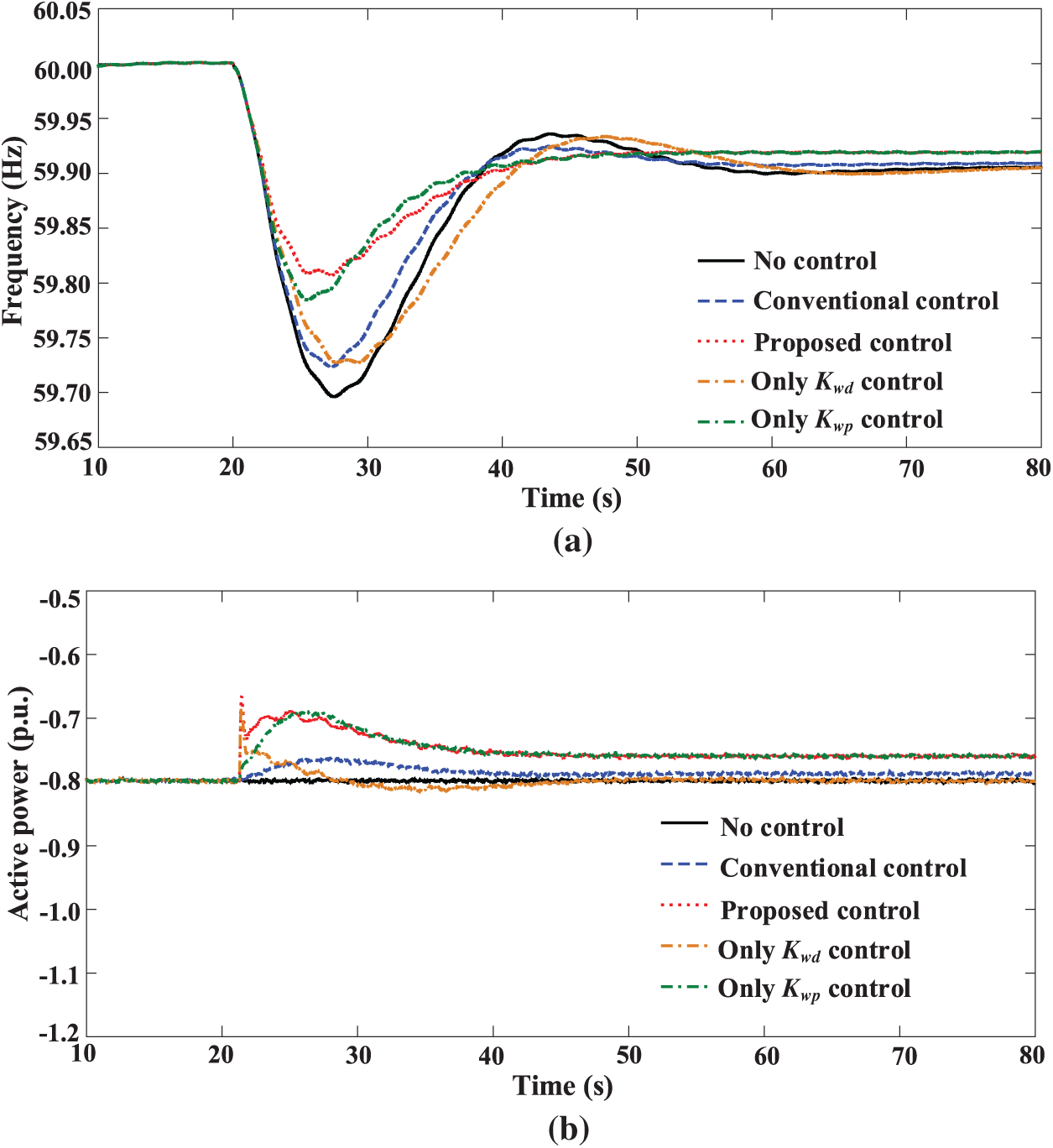

Figure 16: Response results of system when DFPSU adopts different frequency control strategies in pumping mode: (a) frequency; (b) active power of DFPSU; (c) speed of DFPSU
A subsequent examination of the system’s response during the proposed control with solely proportional and differential control reveals the efficacy of differential control during the initial phase of frequency control, characterized by a substantial value of
As demonstrated in the preceding analysis, the differential control channel is analogous to virtual inertia control, a strategy that has been proven to effectively suppress frequency changes and, by extension, reduce
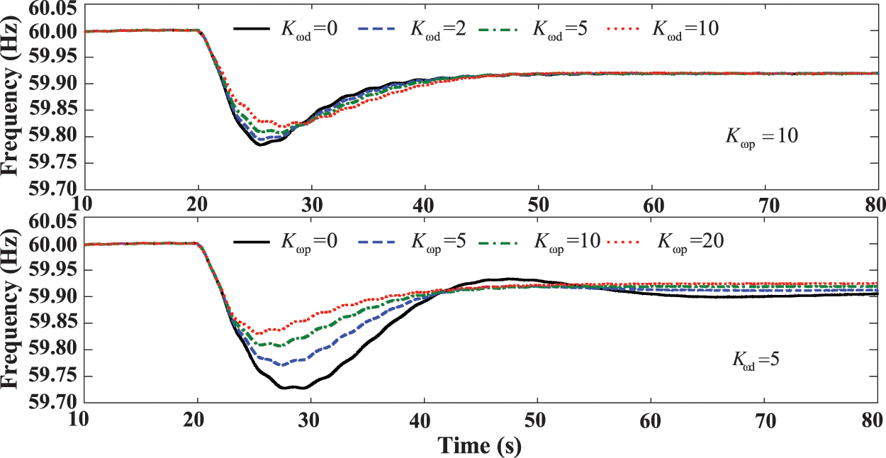
Figure 17: Response results of system under different parameters
5.2 Simulation Verification of Adaptive Variable-Parameter Frequency Control Strategy
In the event that the DFIM-PSH is operating in pumping mode, the dynamic response curves of the system at unit input powers of −0.7 and −0.9 p.u. are demonstrated in Figs. 18 and 19, respectively. Concurrently, a variable-parameter frequency control strategy can attain optimal frequency control outcomes. The DFIM-PSH adjusts the input active power by altering the speed, thereby providing stable power support to reduce
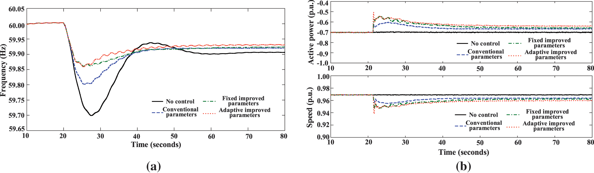
Figure 18: Response results of the system when DFPSU in sub-synchronous pumping mode: (a) system frequency; (b) active power and speed of DFPSU
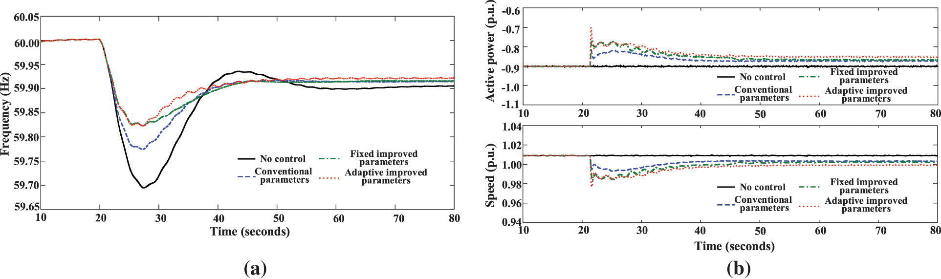
Figure 19: Response results of the system when DFPSU in super-synchronous pumping mode: (a) system frequency; (b) Active power and speed of DFPSU
In comparison with conventional parameters, the improved parameter–adaptive control facilitates the unit in altering the speed significantly more rapidly at the commencement of frequency control. Consequently, this reduces
Fig. 20 shows the system’s frequency dynamic response index when DFPSU is in different operating conditions and states. As we can see from this analysis, the adaptive variable parameters determined using the method described in this paper can make the most of the rotor kinetic energy and frequency control capacity of the generator set when it is operating in different conditions. At the same time, they can also make sure that the generator set speed and power stay within the limits. In other words, the improved parameters are strong when the generator set is in different operating conditions. At the same time, since the variable parameters also adapt to changes in frequency, each frequency control channel can have a positive effect on restoring the correct frequency throughout the entire process. As well as reducing
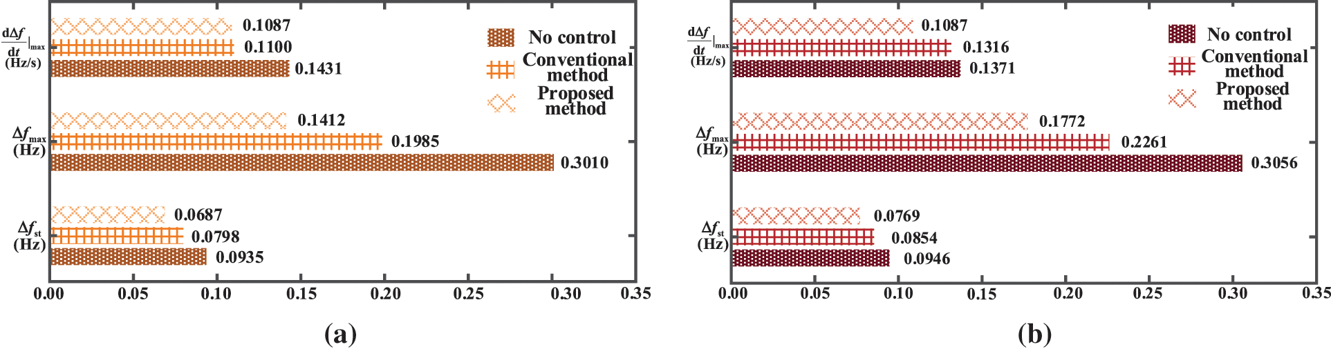
Figure 20: Frequency dynamic response indexes under different frequency control parameters: (a) sub-synchronous state; (b) super-synchronous state
This paper designs a frequency control module for the DFPSU under pumping conditions, and constructs a low-order frequency response model to analyze its inertia response and Primary Frequency Control characteristics and related influencing factors. It is on this basis that an adaptive variable-parameter frequency control strategy is proposed. This strategy is designed to take into account the safe and stable operation of the unit and the characteristics of frequency variation. The innovation lies in the real-time adjustment of the amplitude and sign of specific parameters with frequency variation, which ensures that each frequency control channel can effectively promote frequency restoration throughout the entire frequency control process, and that the frequency control capability can be maximized on the premise of maintaining safe and stable operation. The validity of the proposed approach is substantiated by simulation verification, which demonstrates that the frequency control module constructed in this paper, which converts
Acknowledgement: Not applicable.
Funding Statement: The authors received no specific funding for this study.
Author Contributions: The authors confirm contribution to the paper as follows: Conceptualization, Shuxin Tan and Wei Yan; methodology, Shuxin Tan and Wei Yan; software, Lei Zhao and Ziqiang Man; validation, Yu Lu, Wei Yan and Teng Liu; formal analysis, Lei Zhao, Yu Lu and Ziqiang Man; investigation, Yu Lu, Wei Yan and Teng Liu; resources, Gaoyue Zhong and Weiqun Liu; data curation, Gaoyue Zhong and Weiqun Liu; writing—original draft preparation, Xianglin Zhang and Yu Lu; writing—review and editing, Shuxin Tan, Wei Yan and Linjun Shi; visualization, Shuxin Tan, Xianglin Zhang and Wei Yan; supervision, Lei Zhao; project administration, Lei Zhao and Linjun Shi; funding acquisition, Ziqiang Man. All authors reviewed the results and approved the final version of the manuscript.
Availability of Data and Materials: The data that support the findings of this study are available from the corresponding author, Xianglin Zhang, Hohai University, upon reasonable request.
Ethics Approval: Not applicable.
Conflicts of Interest: The authors declare no conflicts of interest to report regarding the present study.
Abbreviations
| DFPSU | Double-Fed Pumped Storage Units |
| DRL | Deep Reinforcement Learning |
| RSC | Rotor Side Converter |
| GSC | Grid Side Converter |
| DFIM | Double-Fed Induction Motor |
| SVR | Support Vector Regression |
| SFR | System Frequency Response |
| TD3 | Twin delayed deep deterministic policy gradient |
| DDPG | Deep Deterministic Policy Gradient |
| MDP | Markov Decision Process |
Appendix A
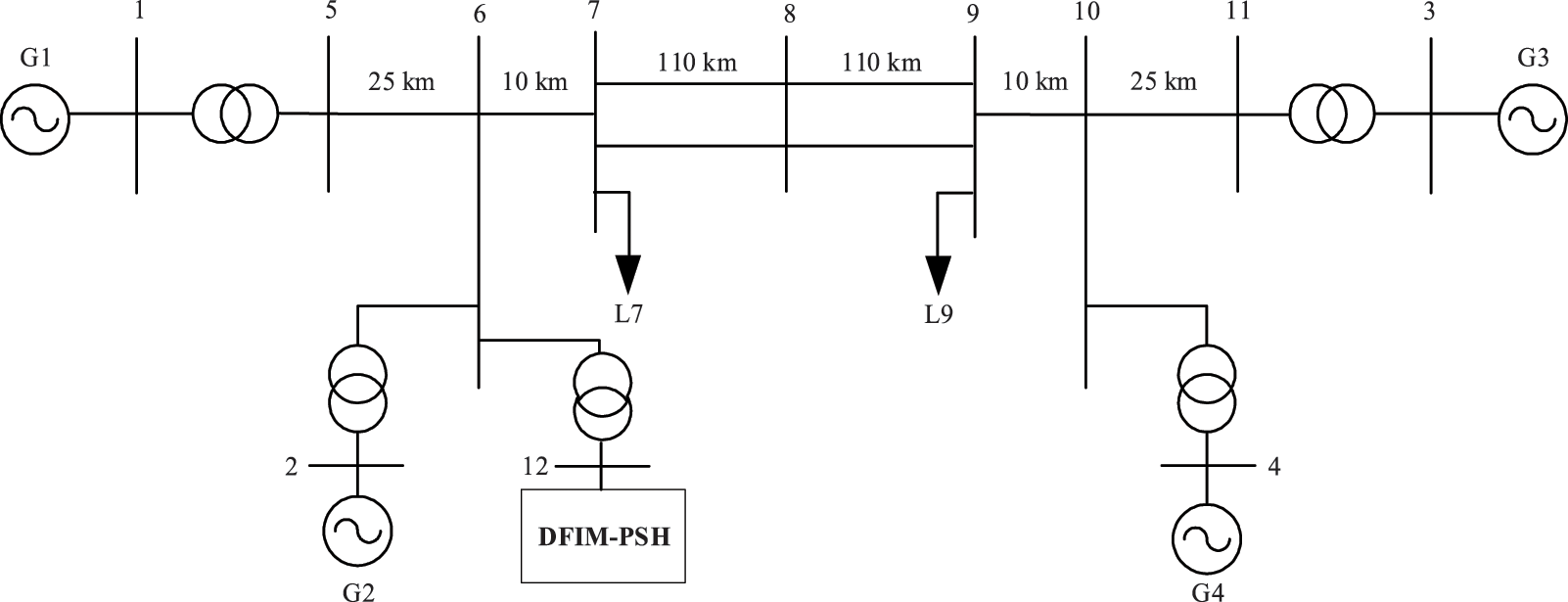
Figure A1: Schematic diagram of DFIM-PSH connecting to a four-machine two-zone system
References
1. Donalek PJ. Pumped storage hydro: then and now. IEEE Power Energy Mag. 2020;18(5):49–57. doi:10.1109/mpe.2020.3001418. [Google Scholar] [CrossRef]
2. Li H, Liu H, Song E, Xiao HW, Luo L, Huang ZX. Improved virtual inertia control strategy of doubly fed pumped storage unit for power network frequency modulation. Autom Electr Power Syst. 2017;41(10):58–65. doi:10.7500/AEPS20160706008. [Google Scholar] [CrossRef]
3. Yu CY, Zhu Y, Gao GY. Control strategies for rapid power responses of doubly-fed hydro generators. J Hydroelectr Eng. 2019;38(5):89–96. doi:10.11660/slfdxb.20190510. [Google Scholar] [CrossRef]
4. Li H, Huang Z, Liu H, Song E, Xiao H, Luo L, et al. Control strategy of rapid power response for AC excited pump storage unit. Electr Power Autom Equip. 2017;37(11):156–61. doi:10.16081/j.issn.1006-6047.2017.11.025. [Google Scholar] [CrossRef]
5. Lung JK, Lu Y, Hung WL, Kao WS. Modeling and dynamic simulations of doubly fed adjustable-speed pumped storage units. IEEE Trans Energy Convers. 2007;22(2):250–8. doi:10.1109/TEC.2006.875481. [Google Scholar] [CrossRef]
6. Kruger K, Koutnik J. Dynamic simulation of pump-storage power plants with different variable speed configurations using the simsen tool. Int J Fluid Mach Syst. 2009;2(4):334–45. doi:10.5293/ijfms.2009.2.4.334. [Google Scholar] [CrossRef]
7. Chen Y, Xu W, Liu Y, Bao Z, Mao Z, Rashad EM. Modeling and transient response analysis of doubly-fed variable speed pumped storage unit in pumping mode. IEEE Trans Ind Electron. 2023;70(10):9935–47. doi:10.1109/TIE.2022.3224154. [Google Scholar] [CrossRef]
8. Huang W, Chen W, Wu J. Auxiliary frequency modulation method of DFIG-based wind turbine based on principle of power balance control. Electr Power Autom Equip. 2019;39(1):66–72. doi:10.16081/j.issn.1006-6047.2019.01.010. [Google Scholar] [CrossRef]
9. Gulzar MM, Sibtain D, Khalid M. Innovative design for enhancing transient stability with an ATFOPID controller in hybrid power systems. J Energy Storage. 2024;99:113364. doi:10.1016/j.est.2024.113364. [Google Scholar] [CrossRef]
10. Zhu Z, Pan W, Liu T, Li Y, Liu M. Dynamic modeling and eigen analysis of adjustable-speed pumped storage unit in pumping mode under power regulation. IEEE Access. 2021;9:155035–47. doi:10.1109/access.2021.3128627. [Google Scholar] [CrossRef]
11. Chen Y, Xu W, Liu Y, Rashad EM, Bao Z, Jiang J, et al. Reduced-order system frequency response modeling for the power grid integrated with the type-II doubly-fed variable speed pumped storage units. IEEE Trans Power Electron. 2022;37(9):10994–06. doi:10.1109/TPEL.2022.3166567. [Google Scholar] [CrossRef]
12. Shi L, Lao W, Wu F, Zheng T, Lee KY. Frequency regulation control and parameter optimization of doubly-fed induction machine pumped storage hydro unit. IEEE Access. 2022;10:102586–98. doi:10.1109/access.2022.3208960. [Google Scholar] [CrossRef]
13. Fan P, Ke S, Yang J, Li R, Li Y, Yang S, et al. A load frequency coordinated control strategy for multimicrogrids with V2G based on improved MA-DDPG. Int J Electr Power Energy Syst. 2023;146:108765. doi:10.1016/j.ijepes.2022.108765. [Google Scholar] [CrossRef]
14. Hu J, Niu H, Carrasco J, Lennox B, Arvin F. Voronoi-based multi-robot autonomous exploration in unknown environments via deep reinforcement learning. IEEE Trans Veh Technol. 2020;69(12):14413–23. doi:10.1109/tvt.2020.3034800. [Google Scholar] [CrossRef]
15. Fujimoto S, Hoof H, Meger D. Addressing function approximation error in actor-critic methods. In: Proceedings of the 35th International Conference on Machine Learning; 2018 Jul 10–15; Stockholm, Sweden. p. 1587–96. [Google Scholar]
16. Lillicrap TP, Hunt JJ, Pritzel A, Heess N, Erez T, Tassa Y. Continuous control with deep reinforcement learning. arXiv:1509.02971. 2015. doi:10.48550/arXiv.1509.02971. [Google Scholar] [CrossRef]
Cite This Article
 Copyright © 2025 The Author(s). Published by Tech Science Press.
This work is licensed under a Creative Commons Attribution 4.0 International License , which permits unrestricted use, distribution, and reproduction in any medium, provided the original work is properly cited.
 Downloads
 Citation Tools