
 Submit a Paper
 Propose a Special lssue
 Open Access
ARTICLE
Power Balance Control Strategy of Cascaded H-Bridge Multilevel Inverter Based on Improved Harmonic Injection
School of Automation and Electrical Engineering, Lanzhou Jiaotong University, Lanzhou, 730070, China
* Corresponding Author: Haonan Xu. Email:
(This article belongs to the Special Issue: Construction and Control Technologies of Renewable Power Systems Based on Grid-Forming Energy Storage)
Energy Engineering 2025, 122(12), 4987-5000. https://doi.org/10.32604/ee.2025.068714
Received 04 June 2025; Accepted 08 August 2025; Issue published 27 November 2025
 View Full Text
 Download PDF
Abstract
The cascaded H-bridge (CHB) multilevel inverter has become one of the most widely used PV inverter topologies due to its high voltage processing capability and high quality output power. Grid-connected PV system due to external conditions such as PV panel shading, PV component damage, can lead to PV output power imbalance, triggering the system over-modulation phenomenon, which in turn leads to grid-connected current waveform distortion. To this end, an improved power balance control strategy is proposed in this paper. Firstly, according to the different modulation ratios of each H-bridge module, a suitable harmonic injection method is used to keep the peak value of the modulating waveform always at 1; then an inverse triangular trapezoidal waveform is injected to optimize the modulating waveform, which further improves the output voltage waveform, reduces the THD value of the grid-connected currents, and maintains the stability of power inside the CHB system. Purpose. Simulation verifies the effectiveness and feasibility of this power balance control strategy.Keywords
In order to alleviate the pressure of growing energy demand without damaging the environment, in recent years, the share of renewable energy sources (e.g., solar, ocean, and wind) in the power system has been increasing annually, and has gradually become an important direction to promote the transformation of the energy structure. Among them, solar power is regarded as one of the fastest-growing and most promising green energy sources due to its low carbon emissions and non-pollution advantages.
With the rapid construction of small, medium and large-scale photovoltaic (PV) power plants, PV systems are facing many challenges, including how to improve PV utilisation, optimise the stability of grid-connected currents to meet the demands of user loads, and prolonging the service life of the equipment. Therefore, it is of great significance to study and propose effective strategies to solve these problems in order to realise the wide application of PV power generation [1].
The cascaded H-bridge multilevel inverter (CHB) is widely used as the preferred topology in modern grid-connected PV systems due to its modularity, high reliability, high efficiency and good power quality. Compared with the traditional two-level inverter, the cascaded H-bridge multilevel inverter can output multilevel through step-wave modulation, which significantly reduces the harmonic content in the output current.
The filter design adopts a single inductor output structure, which can effectively avoid the resonance risk of LCL filter. Using low-voltage and high-efficiency modular technology, this topology significantly improves the reliability of the system and makes it easy to achieve large-scale production. The design feature of no frequency transformer enables the output current to be directly connected to the medium voltage grid, simplifying the system structure and reducing the nighttime power consumption of the PV inverter to a certain extent [2,3].
External environmental factors (e.g., cloud cover, dust or leaves on the surface of the PV panel) can lead to uneven light intensity received by the PV module, triggering a power imbalance. At the same time, module failure can also cause the switch between it and the H-bridge to be disconnected, resulting in an imbalance in the power generated by the cascaded H-bridge. Both of these situations trigger the phase-to-phase power imbalance problem in the three-phase CHB PV grid-connected inverter. The H-bridge unit corresponding to the PV module with higher output power may be at risk of over-modulation, which increases the harmonic components of the grid current, affects the quality of the grid-connected current, and, in severe cases, causes system instability.
In order to solve the power imbalance phenomenon caused by external environmental problems, in-depth research has been carried out at home and abroad for this problem. Literature [4] proposed a new concept of identical modular magnetic chain using third harmonic injection 60-degree bus-clamped pulse width modulation (PWM) technique, which has better spectral characteristics can improve the quality of grid-connected current and reduce switching losses, but there are still more high harmonics. Literature [5] proposed a third harmonic injection equal load 90 degree clamped PWM (THELNDCPWM) technique which can reduce the total harmonic distortion (THD) and power loss during SMES discharge. Literature [6–8] achieved mutual cancellation of harmonic components in the total output voltage by introducing multiple harmonic components in the overmodulation module and injecting reverse harmonics in the non-overmodulation module, which extends the linear modulation range of the system from 1.155 to 1.270, but the active power of the high power H-bridge fails to fully utilise its maximum output potential. Literature [9,10] proposed a novel harmonic compensation control method by injecting an appropriate amount of fundamental waveform components into the modulating waveforms of the overmodulated units and injecting the 3rd and 5th harmonics to ensure that the peak value of the modulating waveforms is always maintained at 1. At the same time, in order to avoid the un-overmodulated units to trigger the reverse overmodulation due to the initial harmonic injections, the reverse harmonic components are introduced to these units, which avoids the instability of the system. Literature [11] proposed an advanced PWM technique to improve the linear modulation range by injecting square waves to achieve the minimum compensation to reduce the power loss and voltage THD. Literature [12] proposed a hybrid photovoltaic-storage power routing based on the cascaded H-bridge (CHB) structure, which is efficiently achieved by configuring a small number of storage modules in a three-phase CHB PV inverter and utilising the synergistic PV and storage control strategy to maintain the internal power balance of the CHB system. Literature [13] proposes a power balance control strategy with a dual min-max zero-sequence injection method, clarifies the generation mechanism of the power imbalance problem based on the voltage-current vector diagram of the inverter, and analyses and compares the composition of different zero-sequence injection methods and their implementation methods. Literature [14] proposes an Modified Modulation Waveform Injection Strategy (MMWIS), in which the fine-tuning quantity in the traditional modulated waveform injection strategy is improved by taking a part of the difference between the square waveform with amplitude ±1 and in phase with the current and the modulated waveform as the fine-tuning quantity, so as to extend the maximum modulation ratio of the high-power module to π/4, and make its output active power reach the maximum value of the output it is able to produce. Literature [15] proposes a trapezoidal wave compensation control method. When the system operates beyond the linear modulation region of trapezoidal wave compensation, the power adaptive control strategy is used to dynamically adjust the output power of the front-stage microsource, thus effectively preventing the occurrence of over-modulation phenomenon.
Existing studies have proposed a variety of power balance control strategies for power imbalance conditions, and although the grid-connected current distortion is effectively suppressed, the total harmonic distortion (THD) of the system grid-connected current is still significantly higher than that of the power balance state under non-ideal operating conditions. Therefore, it is still necessary to further improve the grid-connected power quality by optimising the modulating waveform.
In this paper, an improved power balance control strategy is proposed, which adopts different harmonic compensation strategies according to the difference of modulation ratios of each H-bridge module, and at the same time injects the inverse triangular trapezoidal waveform into the modulating waveform to change the amplitude distribution of the waveform, so that the modulating waveform shape is more uniform, and achieves the purpose of reducing the THD value of the grid-connected current and the loss of the system. A three-phase seven-level solar photovoltaic grid-connected system is designed based on cascaded H-bridge topology and the proposed power balance control strategy is analysed in terms of total harmonic distortion (THD) of the grid-connected current.
2 Improved Power Balance Control Strategy and Mathematical Model Analysis
2.1 Analysis of Single-Phase Cascaded H-Bridge Mathematical Model
Fig. 1 shows the CHB PV grid-connected inverter topology with A-phase as an example, each H-bridge module Comprises four switching tubes (
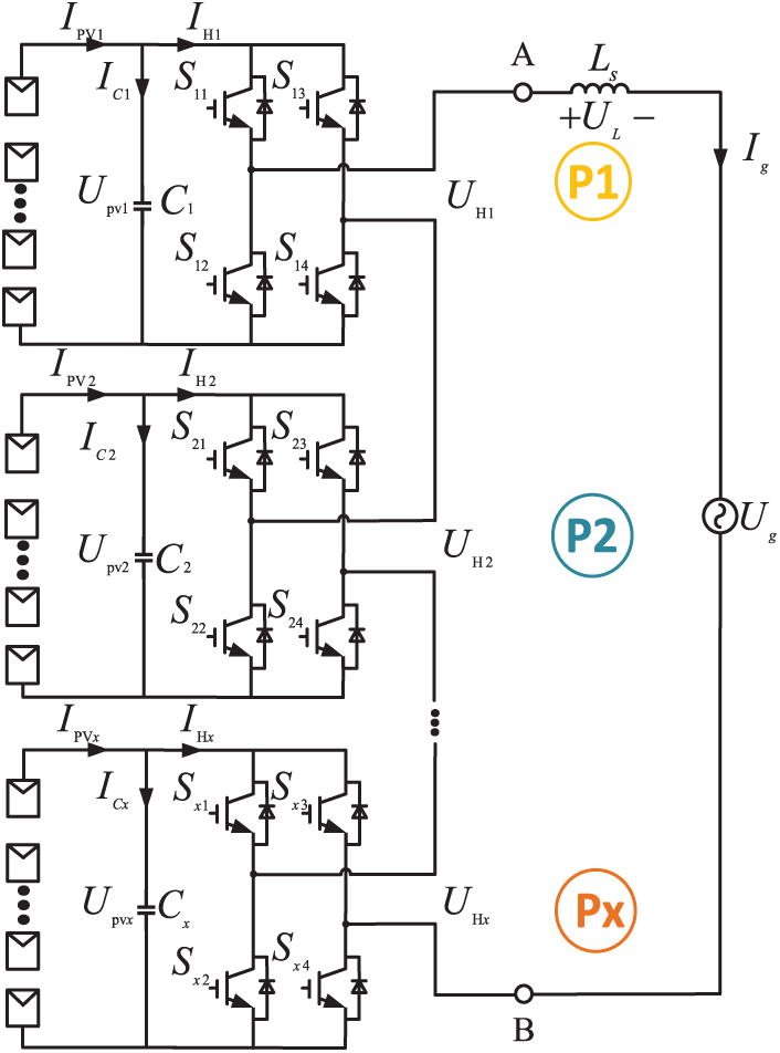
Figure 1: Topology of A-phase CHB photovoltaic grid-connected inverter
The outputs of the cascaded H-bridge are connected in series, and due to shading of the PV panels or damage to the PV modules, the output power of the PV modules belonging to the cascaded H-bridge decreases, leading to a reduction in the total output power
Under this condition, for the H-bridge module with changing output power, Voltage compensation is required for the H-bridge module with varying output power. However, overcompensation would increase the modulating waveform amplitude, resulting in system overmodulation, and the system will be overmodulated.
The modulating wave A for the number
According to Kirchhoff’s law, the mathematical model of the AC side can be expressed as follows, ignoring line resistance and switching losses:
Eq. (4) can be rewritten by means of vector analysis as:
where
As depicted in the vector diagram of Fig. 2, when the inverter operates at unit power factor, the voltage component
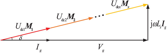
Figure 2: Phasor diagram of CHB operating at unity power factor
2.2 Stability Domain Range Analysis
During unit power factor operation, the peak value of the modulating wave for each unit is less than 1. At this time, the amplitude of the modulating wave is
The active power injected into the grid by the x-th H-bridge unit is expressed as:
where
Define the active power on the DC side of the x-th H-bridge to be expressed as:
where
That is, the RMS value of the grid current is not less than the times of the output current of each PV module, i.e.,
2.3 Improved Power Balance Control Strategy
It has been investigated to extend the effective linear modulation range of the inverter to 1.270 by means of harmonic compensation control strategy. The power balance control strategy proposed in this paper achieves the optimisation of the modulation waveform by dynamically adjusting the modulation ratio of each H-bridge unit.
As shown in Table 1, according to the size of the modulation ratio, the system operating region is divided into four stages, and different harmonic compensation methods are used in each stage.

Combined with the inverse triangular trapezoidal waveform injection method in the power balance state proposed in the literature 18, this study extends it to the power imbalance state, and achieves synergistic control of harmonic compensation and waveform optimisation by adjusting the phase and amplitude of the injected waveform, which further reduces the THD value of the grid-connected current. Good results are also demonstrated through simulation.
Fig. 3 shows a schematic diagram of the 3rd harmonic compensation, where a synthetic modulating waveform
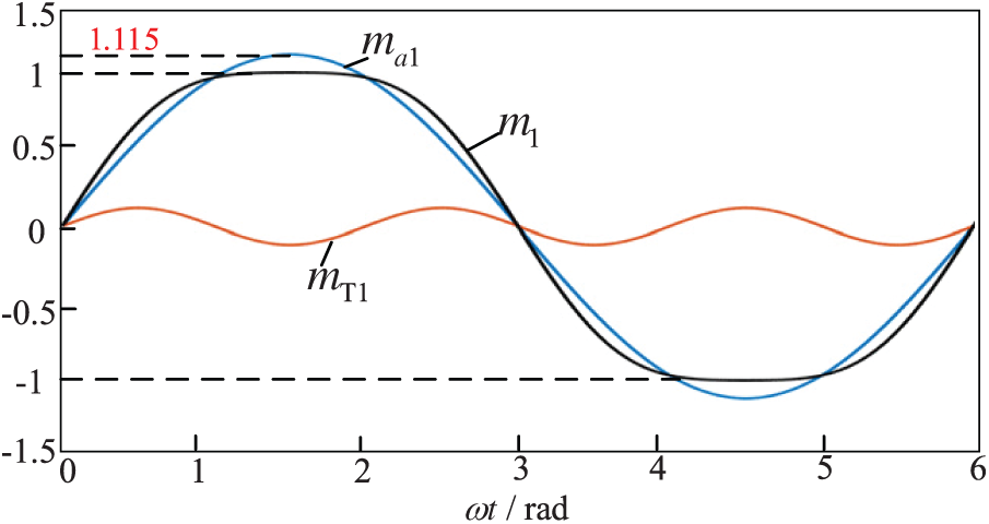
Figure 3: Schematic diagram of third harmonic injection
The synthesised modulated wave
Fig. 4 shows the schematic after injecting the 3rd and 5th harmonics into the modulating wave of the overmodulation unit, at which point the system reaches a linear modulation range of 1.270.
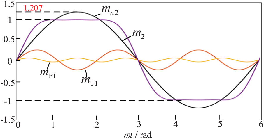
Figure 4: Schematic diagram of third and fifth harmonic injection
In Fig. 4,
The modulated wave
Fig. 5 shows the fundamental compensation method, by introducing an appropriate amount of inverted fundamental wave into the overmodulation unit, this mode is used for modulation ratios in the range of 1.207–1.270.
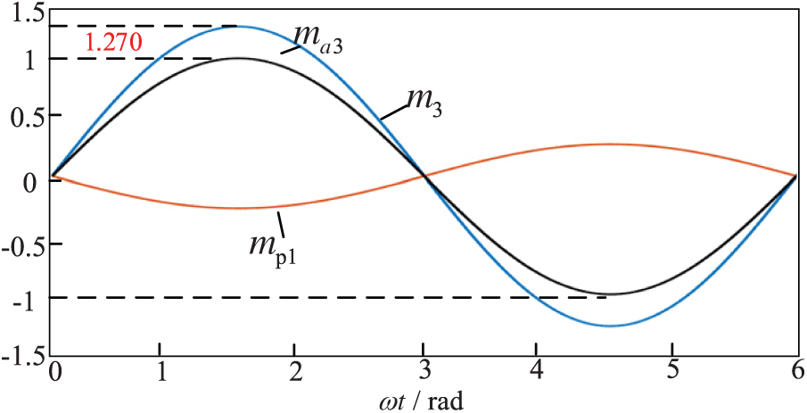
Figure 5: Schematic diagram of fundamental wave injection
In the figure,
The methods of harmonic compensation under different modulation regimes are given in Figs. 3–5. Different light intensity causes different modulation ratios for different H-bridge modules, so different harmonic compensation control strategies are used for different H-bridge modules in case of system power imbalance.
For the non-over-modulated units need to compensate for an equal amount of inverse harmonics, and the compensation of inverse harmonics raises the peak value of the modulating waveform to 1 to further improve the quality of the output current waveform.
On the basis of the harmonic compensation control strategy mentioned above, the triangle wave saturation common mode control strategy proposed in reference [16] is integrated. As shown in Fig. 6, the CHB injects multiple harmonics and then injects an inverse triangular-trapezoidal waveform to improve the linearity and harmonic characteristics of the output voltage by optimising the shape of the modulating waveform, increase the effective output voltage by changing the peak position of the modulating waveform, reduce the amplitude of the low-frequency harmonics, and concentrate the high-frequency harmonics in a higher frequency band, eliminating the influence of the high-frequency subharmonics, which is easy to be suppressed by a filter.
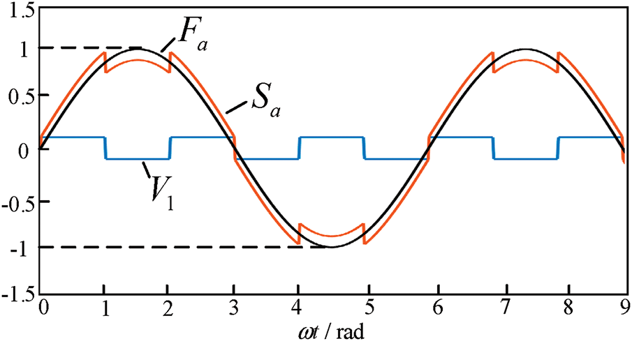
Figure 6: The triangular-trapezoidal wave injection strategy
The specific implementation method is as follows, the modulating waveform is sinusoidal modulating signal
where A is the modulating wave amplitude, according to the amplitude phase of the modulating wave to generate an inverse triangular wave, by limiting the amplitude to within
where
3 System Control Block Diagram Analysis
3.1 Voltage-Current Double Closed-Loop Overall Control Strategy
The overall control structure of the three-phase CHB seven-level PV grid-connected inverter is shown in Fig. 7, including three parts: the MPPT control, the voltage-current dual-loop control and the improved power balance control. Among them, the independent MPPT control algorithm adopts the conductance increment method, which is simple to implement and can effectively reduce the power fluctuations near the maximum power point, showing good control performance.
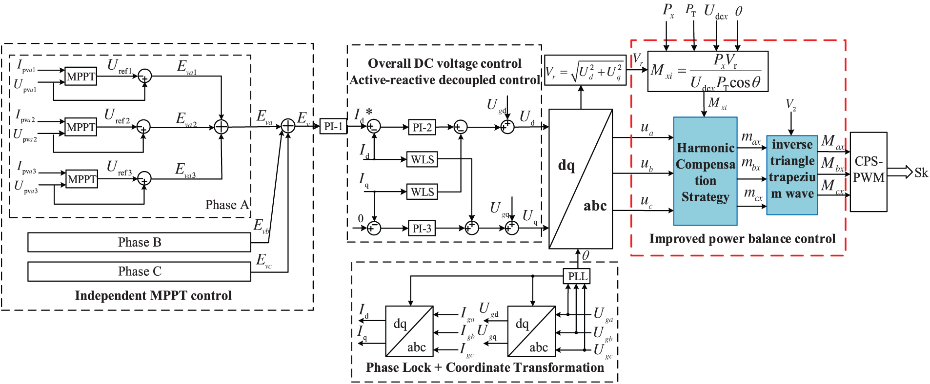
Figure 7: System control block diagram
The voltage outer loop adopts the overall DC-side voltage error control, the DC-side voltage control through the independent decoupling of active and reactive currents of the inverter, the control purpose is to make
3.2 Calculation of Modulated Waves
Equations in display format should be separated from the surrounding text, aligned to the left of the column, with the equation label aligned to the right margin. Equations must be editable and numbered consecutively in Arabic numerals within parentheses, where applicable. See Eq. (1) for an example:
The inner loop outputs the co-modulation ratio
where
The modulated waveform
where
4 Simulation and Result Analysis
The Institute of Electrical and Electronics Engineers (IEEE) has issued a standard that recommends that the total harmonic distortion (THD) of the grid-connected current should not exceed 5% for low-voltage equipment connected to the public power grid.
In order to verify the feasibility and effectiveness of the power balance control strategy of the three-phase cascaded H-bridge PV grid-connected inverter proposed in this paper, a Simulink simulation model of a seven-level PV grid-connected system with a cascade of three H-bridge units is constructed with the specific parameters of the circuits as shown in Table 2 and the parameters of the PV modules as shown in Table 3.


Simulation Verification
In the simulation setup, the PV panel temperature and solar radiation intensity of the three units are the same at the initial moment, and the solar radiation intensity is set to 1000
Fig. 8 shows the variation curve of the DC side voltage

Figure 8: Schematic of injecting fundamental waves into modulated waves
At 0.4 s, the light intensity changes abruptly, causing the system entering a state of power imbalance. At this moment, the DC-side voltages of Unit 1, Unit 2, and Unit 3 stabilize at 218, 182, and 180 V, respectively. The corresponding output powers are 5070, 3175, and 3170 W, respectively, representing a significant decrease in output power compared to the normal operating state.
Fig. 9 illustrates the modulation waveform of the single-phase cascade H-bridge, using the A-phase as an example. The modulation waveform of Module 1 reaches a peak value of 1 during normal operation. However, over-modulation occurs after 0.4 s when the light intensity changes, resulting in a modulation ratio of 1.17. At this point, the system experiences over-modulation. In contrast, the modulation waveforms of Modules 2 and 3 do not exhibit over-modulation after 0.4 s, with their peak values reaching 0.89.

Figure 9: Modulation waveform of single-phase cascaded H-bridge
When the system does not implement any power control strategy, the grid-connected current waveform is illustrated in Fig. 10. Under constant light intensity, the Total Harmonic Distortion (THD) of the grid-connected current is 0.83%. Over-modulation occurs at 0.4, and after 0.8 s, the grid-connected current reaches 5.33%, which is abnormal and does not meet the requirements for grid connection.
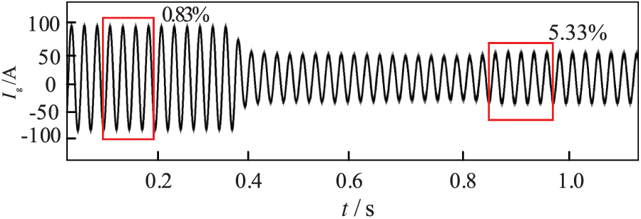
Figure 10: THD value of grid-connected current without control strategy
According to Fig. 11, it can be obtained that the sudden change in light causes the system to over-modulate after 0.4 s. The modulation ratio at this time is 1.17. The 3rd and 5th harmonic injection methods are used to reduce the modulating wave crests at 0.4 s. The modulated current THD value is reduced to 3.22% compared to that without the harmonic injection strategy. The THD value of the system’s grid-connected current is reduced to 3.22% after 0.8 s compared to that without the harmonic injection strategy.
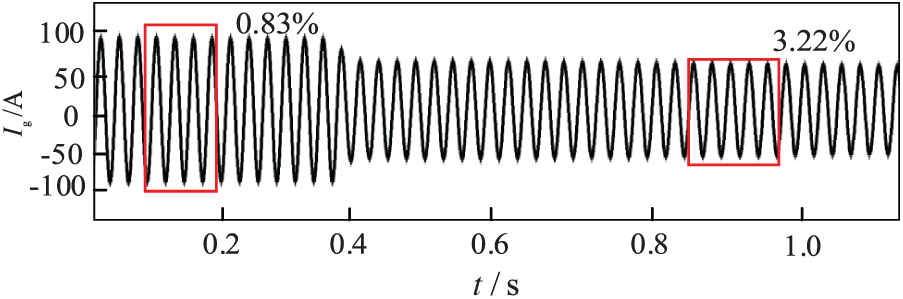
Figure 11: THD value of grid-connected current with third and fifth harmonic injection
When the improved harmonic compensation control strategy proposed in this paper is adopted, the 3rd and 5th harmonics are injected into the over-modulation module, while the inverse harmonics are injected into the unmodulated module, while so that the peak value of the modulating wave of each module is just 1, and finally the inverse triangular trapezoidal wave is injected. At this time, the grid-connected current waveform is shown in Fig. 12, from which it can be seen that the THD value of the grid-connected current has decreased significantly compared with that of the grid-connected current that adopts the 3rd and 5th harmonic injection control strategy, and the harmonic distortion value of the current stabilises at 2.00% at around 0.8 s.
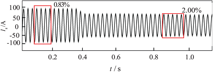
Figure 12: Current THD value using the improved power balance control strategy
Fig. 13 depicts the comparison of THD values of grid-connected currents between the existing and proposed power balancing control strategies. The comparison in the figure shows that the fusion control strategy proposed in this paper significantly optimises the harmonic performance. Compared with the system without balancing strategy, the new method thoroughly improves the waveform quality; compared with the traditional third and fifth harmonic injection schemes, the additional inclusion of inverse triangular trapezoidal wave effectively suppresses the specific subharmonic amplification problem, resulting in smaller current distortion.

Figure 13: Comparison of THD values of grid-connected current
The improved power balance control strategy has the following advantages:
(1) Different harmonic compensation injection strategies are used according to the range of overmodulation of the H-bridge module, which solves the overmodulation problem of the system and enables the CHB grid-connected inverter to operate stably under the input power imbalance condition.
(2) By injecting an inverse triangular trapezoidal waveform, the waveform of the modulating waveform can be optimised to further improve the quality of the output voltage waveform, ultimately improving the quality of the grid-connected current.
The improved power balance control strategy proposed in this paper is simple, without additional hardware requirements and easy to implement.
Moreover, the proposed power balance control strategy for cascaded H-bridge inverters can be applied in many important fields:
Such as solving the power imbalance problem in photovoltaic power plants to improve the power generation efficiency; coordinating the power fluctuation of different energy sources in wind-solar-storage microgrids to enhance the stability of the system; and responding to the changes in the power grid quickly at the electric vehicle charging station to ensure the smooth charging. This strategy significantly improves the overall performance of new energy systems.
Acknowledgement: Sincere thanks to Professor Zhao from Lanzhou Jiaotong University for his full support.
Funding Statement: This work was supported by the National Natural Science Foundation of China, Regional Science Foundation Project, 52367009, Study on Bow Net Dynamics Modeling and Coupling Smoothness of High speed AC Rigid Network in the Long Tunnel Section of Sichuan Tibet Railway.
Author Contributions: The contributions to this paper are as follows: research idea and design: Feng Zhao, Haonan Xu; data collection: Haonan Xu, Xiaoqiang Chen, Ying Wang; results analysis and interpretation: Feng Zhao, Haonan Xu; first draft: Haonan Xu, Xiaoqiang Chen. All authors reviewed the results and approved the final version of the manuscript.
Availability of Data and Materials: Data is available on request from the authors. The data that support the findings of this study are available from the corresponding author, upon reasonable request.
Ethics Approval: Not applicable.
Conflicts of Interest: The authors declare no conflicts of interest to report regarding the present study.
Nomenclatures
| Output voltage and output current of the PV module | |
| Filter capacitor | |
| DC side current and voltage | |
| AC output voltage | |
| Grid voltage and grid current | |
| Filter inductor | |
| Maximum output power (W) | |
| Open circuit voltage (V) | |
| Maximum power point voltage (V) | |
| Maximum power point current (A) | |
| Short-circuit current (A) |
References
1. Jia K, Gu C, Xuan Z, Li L, Lin Y. Fault characteristics of large-scale photovoltaic power plant pooling system and its line protection. J Electrotechnol. 2017;32(9):189–98. (In Chinese). doi:10.19595/j.cnki.1000-6753.tces.2017.09.022. [Google Scholar] [CrossRef]
2. Lashab A, Sera D, Hahn F, Camurca L, Terriche Y, Liserre M, et al. Cascaded multilevel PV inverter with improved harmonic performance during power imbalance between power cells. IEEE Trans Ind Appl. 2020;56(3):2788–98. doi:10.1109/TIA.2020.2978164. [Google Scholar] [CrossRef]
3. Aguilera RP, Acuna P, Yu Y, Konstantinou G, Townsend CD, Wu B, et al. Predictive control of cascaded H-bridge converters under unbalanced power generation. IEEE Trans Ind Electron. 2017;64(1):4–13. doi:10.1109/TIE.2016.2605618. [Google Scholar] [CrossRef]
4. Mahfuz-Ur-Rahman AM, Islam MR, Muttaqi KM, Sutanto D. A magnetic-linked multilevel active neutral point clamped converter with an advanced switching technique for grid integration of solar photovoltaic systems. IEEE Trans Ind Appl. 2020;56(2):1990–2000. doi:10.1109/TIA.2020.2965915. [Google Scholar] [CrossRef]
5. Mahfuz-Ur-Rahman AM, Islam MR, Muttaqi KM, Sutanto D. An advance modulation technique for single-phase voltage source inverter to integrate SMES into low-voltage distribution. IEEE Trans Appl Supercond. 2019;29(2):1–5. doi:10.1109/TASC.2018.2882381. [Google Scholar] [CrossRef]
6. Wang M, Zhang X, Zhao T, Ma M, Hu Y, Wang F, et al. Harmonic compensation strategy for single-phase cascaded H-bridge PV inverter under unbalanced power conditions. IEEE Trans Ind Electron. 2020;67(12):10474–84. doi:10.1109/TIE.2019.2962461. [Google Scholar] [CrossRef]
7. Zhao T, Zhang X, Mao W, Wang M, Wang F, Wang X, et al. Harmonic compensation strategy for extending the operating range of cascaded H-bridge PV inverter. IEEE J Emerg Sel Top Power Electron. 2020;8(2):1341–50. doi:10.1109/JESTPE.2019.2895113. [Google Scholar] [CrossRef]
8. Zhao T, Chen D. A power adaptive control strategy for further extending the operation range of single-phase cascaded H-bridge multilevel PV inverter. IEEE Trans Ind Electron. 2022;69(2):1509–20. doi:10.1109/TIE.2021.3060646. [Google Scholar] [CrossRef]
9. Yuan Y, Zhu Q, Lu S, Liu W, Zhang Z. A cascaded H-bridge photovoltaic grid-connected inverter control strategy based on harmonic compensation. Power Autom Equip. 2022;42(12):94–100. (In Chinese). doi:10.1109/appeec.2009.4918598. [Google Scholar] [CrossRef]
10. Wu F, Liu R, Xie Y, Lyu J. A modified power decoupling control strategy for a grid-connected inverter with a low switching frequency under unbalanced grid voltages. Energy Rep. 2022;8:757–68. doi:10.19635/j.cnki.csu-epsa.001192. [Google Scholar] [CrossRef]
11. Chowdhury MR, Rahman MA, Islam MR, Mahfuz-Ur-Rahman AM. A new modulation technique to improve the power loss division performance of the multilevel inverters. IEEE Trans Ind Electron. 2020;68(8):6828–39. doi:10.1109/TIE.2020.3020013. [Google Scholar] [CrossRef]
12. Sun X, Liu X, Teng J, Zhang Y, Zhao W, Li X, et al. Power balancing strategy of cascaded H-bridge photovoltaic inverter based on hybrid configuration of optical storage. Chin J Electr Eng. 2024;44(5):1948–62. (In Chinese). doi:10.13334/j.0258-8013.pcsee.223461. [Google Scholar] [CrossRef]
13. Ye M, Cui H, Song G, Pan T, Han X. Research on power balance control strategy of three-phase CHB multilevel photovoltaic grid-connected inverter. J Power Syst Autom. 2019;31(12):49–54. (In Chinese). doi:10.19635/j.cnki.csu-epsa.000212. [Google Scholar] [CrossRef]
14. Li J, Chen J, Gong C, He Q. A control strategy to improve the power imbalance operation capability of cascaded H-bridge inverters. J Electrotechnol. 2023;38(10):2731–43. (In Chinese). doi:10.19595/j.cnki.1000-6753.tces.220762. [Google Scholar] [CrossRef]
15. Wang X, Li Y, Li J, Ding Y, Xue S. HCSY-MG power balance control strategy based on trapezoidal wave compensation and power adaption. Chin J Electr Eng. 2025;45(7):2645–57. (In Chinese). doi:10.13334/j.0258-8013.pcsee.232214. [Google Scholar] [CrossRef]
16. Haq S, Biswas SP, Hosain MK, Rahman MA, Islam MR, Jahan S. A modular multilevel converter with an advanced PWM control technique for grid-tied photovoltaic system. Energies. 2021;14(2):331. doi:10.3390/en14020331. [Google Scholar] [CrossRef]
Cite This Article
 Copyright © 2025 The Author(s). Published by Tech Science Press.
This work is licensed under a Creative Commons Attribution 4.0 International License , which permits unrestricted use, distribution, and reproduction in any medium, provided the original work is properly cited.
 Downloads
 Citation Tools