
 Submit a Paper
 Propose a Special lssue
 Open Access
ARTICLE
A Non-Intrusive Spiral Coil Heat Exchanger for Waste Heat Recovery from HVAC Units: Experimental and Thermal Performance Analysis
Department of Electrical and Electronics Engineering, SRM Institute of Science and Technology, Kattankulathur, Chennai, 603203, India
* Corresponding Authors: K. Vijayakumar. Email: ,
(This article belongs to the Special Issue: Advanced Energy Management and Process Optimization in Industrial Manufacturing: Towards Smart, Sustainable, and Efficient Production Systems)
Energy Engineering 2025, 122(12), 5149-5173. https://doi.org/10.32604/ee.2025.070889
Received 26 July 2025; Accepted 23 September 2025; Issue published 27 November 2025
 View Full Text
 Download PDF
Abstract
Heating, ventilation, and air conditioning (HVAC) systems contribute substantially to global energy consumption, while rejecting significant amounts of low-grade heat into the environment. This paper presents a non-intrusive spiral-coil heat exchanger designed to recover waste heat from the outdoor condenser of a split-type air conditioner. The system operates externally without altering the existing HVAC configuration, thereby rendering it suitable for retrofitting. Water was circulated as the working fluid at flow rates of 0.028–0.052 kg/s to assess thermal performance. Performance indicators, including the outlet water temperature, heat transfer rate, convective coefficient, and efficiency, were systematically evaluated. The system achieved a maximum outlet water temperature of 67°C and a peak thermal efficiency of 91.07% at the highest flow rate. The uncertainty analysis confirmed reliable measurements within ±3.45%. The monthly energy savings were estimated at 178.35 kWh, accompanied by a reduction in CO2 emissions of up to 187.26 kg, yielding a short payback period of 1.06 years. These results demonstrate the feasibility of spiral-coil heat exchangers as cost-effective and eco-friendly alternatives to conventional electric water heaters. The proposed approach not only enhances the overall energy utilization but also contributes to energy conservation and climate mitigation objectives.Keywords
In recent decades, the need for energy-efficient and environmentally friendly technologies has increased, particularly for building cooling and water heating. HVAC systems play a crucial role in providing thermal comfort in the residential, commercial, and industrial sectors [1]. These systems are proficient at regulating the indoor climate; however, they release a considerable amount of low-grade thermal energy into the surrounding environment as waste, particularly from their condenser units [2]. This waste heat, which is often viewed as a drawback, offers a significant and mostly overlooked energy opportunity. As global concerns regarding energy consumption, carbon emissions, and sustainable development continue to increase, the recovery and reuse of waste heat for secondary applications such as domestic water heating are increasingly attracting the interest of researchers and engineers [3,4]. Numerous studies have explored the practicality and effectiveness of integrating waste-heat recovery systems into HVAC units. Previous studies have explored the effectiveness of heat exchangers situated in refrigerant lines, condenser coils, and integrated systems that utilize thermal storage units, including phase-change materials (PCMs), to capture and reuse recovered heat for water heating during off-peak times [5,6].
Several of these investigations have shown encouraging results in terms of the thermal efficiency and energy conservation. Nonetheless, a notable drawback of earlier methods is the alteration of the HVAC system, which frequently entails changes in the refrigerant circuit or control systems. This not only impacts the unit’s operation and warranty but also restricts the feasibility of retrofitting in current installations [7,8]. This paper presents a new approach that utilizes a non-invasive spiral heat absorber mounted externally on an HVAC outdoor unit to fill the existing gap.
This spiral absorber, made of high-conductivity metal tubing, was carefully placed in the hot-air path of the condenser discharge [9]. This design allows for the effective capture of sensible heat from expelled air, while maintaining the internal operation and structural integrity of the HVAC system. The spiral design increases the surface area for heat transfer, leading to a better heat absorption efficiency while maintaining a compact size [10]. This spiral absorber circulates water, allowing it to absorb heat and increase the temperature, making it suitable for use in domestic or utility hot-water applications [11]. This system’s non-intrusive design makes it an excellent choice for retrofit applications, as it does not necessitate alterations to the internal HVAC circuitry, thus maintaining the system functionality and the manufacturer’s warranty.
This collaborative method not only boosts the water heating performance, but also elevates the overall energy efficiency of the HVAC system. Additionally, the positive impact of this integration on the environment was significant. Air conditioners and HVAC systems play a role in environmental degradation because of their significant electrical energy consumption, which is often sourced from fossil fuels [12]. Additionally, they release warm air into the atmosphere, exacerbating urban heat islands and increasing ambient temperatures. Moreover, traditional water heaters, especially electric models, are recognized as significant users of household energy and play a role in CO2 emissions when fuelled by non-renewable sources [13]. The proposed system plays a crucial role in enhancing energy sustainability by capturing and repurposing the waste heat that would typically go to waste. This innovative approach not only reduces the peak electrical load but also lowers greenhouse gas emissions [14].
Shortening the operating time of the heater effectively decreased thermal losses and reduced the electricity demand on the grid. This study offers a thorough experimental and thermal analysis of an innovative, non-invasive spiral absorber-based heat recovery system integrated into an HVAC outdoor unit [15]. The objective was to demonstrate the practicality of utilizing HVAC waste heat for water-heating applications while maintaining the essential functionality of the core system [16]. This approach offers a range of benefits, including simple installation, energy efficiency, reduced environmental impact, and the ability to scale, making it a practical and sustainable choice for both new buildings and retrofitting existing energy-efficient systems [17,18]. This study presents findings that can significantly influence building-energy management. It provides an affordable yet effective solution aimed at enhancing thermal energy efficiency and minimizing the carbon footprint associated with space cooling and water heating [19,20].
The primary objective of this study is to experimentally investigate and analyse the thermal performance of a heat recovery system that harnesses waste heat from HVAC units for water-heating applications. To enhance energy efficiency and reduce overall energy consumption while ensuring that the air-conditioning system remains undisturbed. This study aims to design and fabricate a spiral absorber for a heat recovery system that can effectively extract waste heat from the condenser outlet of an HVAC unit. Another objective was to experimentally assess the thermal performance of the system across a range of operating conditions, specifically from 0.5 to 2 kg/cm2 and to assess essential thermal parameters, including the temperatures of the inlet and outlet air and water, the rate of heat transfer, and the total energy recovered. This analysis focused on evaluating the effectiveness of the heat exchanger in terms of energy savings and its potential to decrease the load on the HVAC system.
In line with Sustainable Development Goals (SDGs) particularly SDG 7 (Affordable and Clean Energy) and SDG 13 (Climate Action), this study addresses the challenge of reducing energy waste by developing a non-intrusive, externally mounted spiral coil heat exchanger designed to recover and utilize the thermal energy expelled by HVAC systems. Unlike traditional approaches that require modifications to refrigerant lines or internal components, often voiding uncertainties, or complicating retrofitting, this innovative design is externally applied and leverages natural airflow from the condenser fan, ensuring system integrity and ease of installation.
This study aims to demonstrate a scalable, energy-efficient solution that not only reduces electricity consumption but also minimizes greenhouse gas emissions associated with conventional water heating. The proposed system offers significant implications for building energy management, retrofitting strategies, and carbon footprint reduction and contributes significantly to sustainable urban infrastructure and energy resilience.
The primary objective of this study was to experimentally investigate the potential of recovering waste heat from an air conditioner using a spiral-coil heat exchanger for water-heating applications. This study aims to evaluate the thermal performance under varying operating conditions, analyse the transient and long-duration behaviour, and determine the overall efficiency and heat recovery potential. Additionally, this study sought to assess the economic feasibility, environmental benefits, and possible design improvements to enhance sustainability and practical implementation.
The present work introduces several novel aspects and meaningful contributions to the field of waste heat recovery (WHR) from air conditioning systems. While earlier studies largely focused on conceptual designs or conventional exchangers, this research integrates a compact spiral-coil heat exchanger that maximizes heat transfer efficiency with reduced space requirements. A key advancement is the experimental investigation under variable flow rates, which allows a deeper understanding of the influence of the operating conditions on the outlet water temperature, thermal performance, and recovery efficiency. Unlike previous studies, which are limited to technical evaluation, this study also integrates economic and environmental assessments by quantifying electricity savings, payback periods, and CO2 mitigation potential based on region-specific tariffs and emission factors. The inclusion of uncertainty and variability analyses through confidence intervals and sensitivity studies enhances the reliability of the findings, thereby addressing the gap in the existing literature. Finally, scenario modelling at the city scale extends its practical significance, showing the broader impact of widespread WHR deployment on energy demand and emissions reduction.
To address the challenge of thermal energy loss in air-conditioning systems, this study proposes a non-intrusive spiral-coil heat exchanger that recovers waste heat from the outdoor condenser unit of a split-type HVAC system. The methodology shown in Fig. 1 follows a structured experimental approach that emphasizes design optimization, energy recovery assessment, and operational sustainability.

Figure 1: Methodology
2.1 System Design and Materials
To explore energy-efficient water heating using waste heat from air-conditioning systems, a structured experimental methodology was developed, as shown in the flowchart in Fig. 2. The objective was to design and validate a spiral-coil heat exchanger capable of absorbing thermal energy from hot air discharged by the outdoor unit of an air conditioner without altering its original configuration [21].

Figure 2: Flowchart for the entire process of the proposed system
The process begins by identifying the research gap, specifically the underutilization of A.C. condenser heat. Subsequently, a spiral-shaped copper heat exchanger was designed to conform to the circular geometry of an outdoor fan to achieve optimal thermal contact and airflow exposure. This was followed by experimental validation, in which the setup was tested under controlled conditions to assess the real-time heat absorption performance. Next, pressure variation trials were conducted at three pressure levels (0.5, 1, and 2 kg/cm2) to observe their influence on flow stability and thermal transfer. During this phase, the flow rate and time duration were recorded to evaluate the water-heating efficiency under each condition.
The key decision point in the methodology was whether the outlet water temperature reached the target threshold of 45°C. If it does, the system proceeds to a detailed analysis and discussion of thermal performance, efficiency, and sustainability. Otherwise, the system parameters are adjusted (flow rate, pressure, or design refinement) and the cycle is repeated. This systematic approach ensures that the spiral coil design is not only functional but also optimized for maximum heat recovery, operational stability, and energy-saving performance.
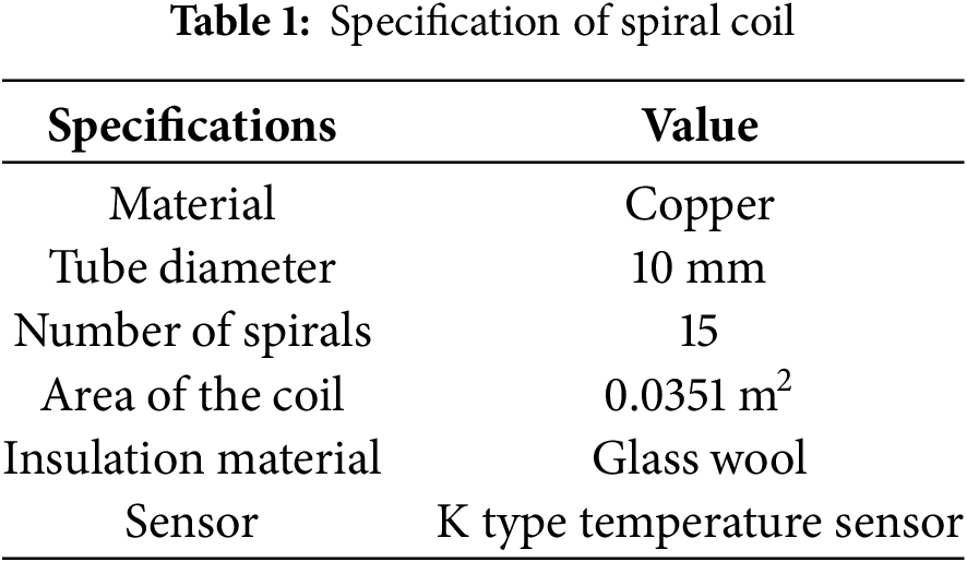
The heat recovery unit consists of a copper spiral coil heat exchanger chosen for its superior thermal conductivity and mechanical durability. The coil was externally mounted in front of the HVAC condenser fan to avoid intrusion into the refrigeration circuit or air-conditioner components. This preserved the operational integrity of the system and facilitated retrofit compatibility. The spiral coil had an outer diameter of 550 mm to match the condenser fan outlet (600 mm) with 15 turns and a total surface area of 0.0351 m2. The copper tubing had a 10 mm outer diameter of 0.6 mm wall thickness. The coil is enclosed within a duct that directs hot airflow over its surface to maximize heat exchange.
Water is used as the heat transfer fluid (HTF), which is circulated by a 2 HP electric pump in a closed-loop system. A 30-L insulated storage tank collected the heated water. Flow control valves and a rotameter ensured accurate adjustment and measurement of the flow rates, which varied across five levels (0.028, 0.033, 0.036, 0.041, and 0.052 kg/s).
To experimentally investigate the feasibility and thermal performance of a waste heat recovery system using an air conditioning unit, a spiral-shaped heat absorber was designed, fabricated, and tested. The primary objective of this system is to extract thermal energy from hot air discharged by the outdoor condenser unit of a conventional split-type air conditioner and use it for water-heating applications. The experimental setup was designed to be nonintrusive, ensuring that the operation of the air conditioner remained unaffected [22].
A spiral-coil heat exchanger was selected as the absorber owing to its geometric compatibility with the circular exhaust area of the air-conditioning unit and its potential for high heat transfer efficiency [23,24]. The spiral geometry was specifically chosen to maximize exposure to the hot air stream of the condenser while maintaining a compact and non-obstructive design. This configuration enables efficient thermal exchange without interfering with the airflow or the mechanical operation of the system [25]. The outer diameter of the spiral coil was designed to be 550 mm, while the outdoor fan diameter was approximately 600 mm, ensuring that up to 90% of the exhaust airflow was exposed to the heat exchanger with Moffat fully covering the fan, thus avoiding the performance deterioration of the air conditioning system [26].
The working fluid used for heat transfer was water, which circulated through the spiral coil using a 2 HP motorized pump. A 30-L capacity water storage tank served as the reservoir for the HTF. The water circuit formed a closed-loop system, where water was pumped from the tank to the absorber and then returned to the tank after passing through the heat exchanger. A flow control valve was installed to regulate the flow rate, and a rotameter was used to measure it accurately [27]. Five different flow rates 0.028, 0.033, 0.036, 0.041, and 0.052 kg/s were tested to determine the optimal conditions for heat absorption as shown in the specification of spiral coil in Table 1. To minimize heat loss along the water piping, the flow lines were insulated with glass wool material.
The spiral coil configuration demonstrated in this study can be scaled for commercial or industrial HVAC units by proportionally increasing the coil length, diameter, or number of parallel coils to handle higher mass flow rates and heat loads. For larger installations, modular coil banks can be integrated to maintain manageable pressure drops, while enhancing the heat transfer surface area. Incorporating forced airflow from condenser fans into such systems can further improve the convective heat recovery. These adaptations make the approach viable not only for residential applications but also for larger-scale HVAC applications, supporting broader energy savings and carbon reduction.
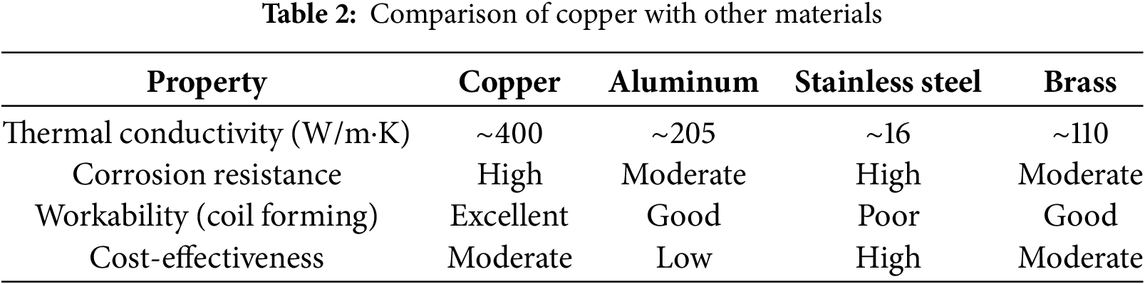
Comparing copper selection with other potential materials
Cu has a very high thermal conductivity (~385–400 W/m·K), which ensures an efficient heat transfer. Compared with other common metals.
• Aluminum: ~205 W/m·K (good but nearly half of copper).
• Stainless steel: ~16 W/m·K (poor, significantly reduced heat exchanger performance).
• Brass: ~110 W/m·K (moderate, less efficient than copper).
Cu naturally resists corrosion in water-based systems. Stainless steel also has good corrosion resistance but at the cost of lower conductivity, as shown in Table 2. Al is prone to corrosion and requires protective coating. Cu is ductile and malleable, making it easy to bend into a spiral coil without cracking. However, it is considerably more difficult to fabricate stainless steels into small coils. Aluminum is lightweight and workable but mechanically weaker.
The air-conditioning unit used in this study was a 5.3 kW-capacity split system that continuously discharged hot air from its condenser. A ducting system was integrated to channel the exhaust air directly over the spiral-coil heat exchanger, thereby ensuring a consistent exposure. The air velocities at the inlet and outlet of the heat exchanger were measured using a digital anemometer, and the air temperatures were recorded using K-type digital thermocouples. The airflow measurements helped estimate the available heat energy in the discharge stream.
Four K-type thermocouples were strategically placed at the following locations to monitor the thermal performance of the system.
• Immediately after the pressure gauge to measure inlet water temperature (T1),
• At the center of the spiral coil (T2),
• At the outlet of the absorber (T3),
• Inside the water storage tank (T4).
The pressure gauge was mounted immediately upstream of the spiral-coil inlet and had a minimum count of 0.1 kg/cm2. The system was operated under three different pressure settings 0.5, 1, and 2 kg/cm2) to evaluate the influence of pressure on the heat absorption efficiency and system stability. A schematic layout and photographic representation of the experimental setup are shown in Figs. 3 and 4, respectively. The results obtained from the experimental runs, along with detailed discussions of the heat-transfer performance under various operating conditions, are presented in the following section.

Figure 3: Experimental setup

Figure 4: Spiral coil used
In addition to the thermal performance assessment, an uncertainty analysis was carried out for the temperature measurements, recognizing that the accuracy of the heat transfer calculations depends heavily on precise temperature readings. This analysis ensured reliability of the experimental data. The recovered heat was calculated based on the temperature differences at the water inlet and outlet, known mass flow rate of water, and specific heat capacity.
The experiments were conducted under ambient outdoor conditions to simulate real-world HVAC operations. The setup was operated from 9:00 a.m. to 4:00 p.m. daily, and data were recorded at regular intervals. To evaluate the system performance, four K-type thermocouples were placed at the water inlet, centre of the coil, water outlet, and inside the storage tank. A digital anemometer and temperature sensors recorded the air velocity and temperature, respectively, at the inlet and outlet of the heat exchanger. The system pressure was varied (0.5, 1.0, and 2.0 kg/cm2) to assess its effect on the flow stability and heat transfer efficiency.
2.3 Performance Metrics and Uncertainty
The key thermal performance parameters were calculated as follows: the outlet water temperature, heat transfer rate (from air to water), convective heat transfer coefficient (CHTC), system thermal efficiency, and heat loss due to ambient exposure.
Thermal Performance Calculations
The heat transferred from air to water can be calculated using the convective heat transfer formula between air and water [28,29]. The amount of heat transferred from the air was calculated using Eq. (1).
where
The amount of heat transferred from air to water was calculated using the following formula:
where
where the
The overall efficiency of the spiral-coil heat exchanger is represented as the difference between the actual and pump efficiencies.
Uncertainty Analysis
The uncertainty of thermal efficiency was measured using the following equation by considering the uncertainty of the instruments:
where
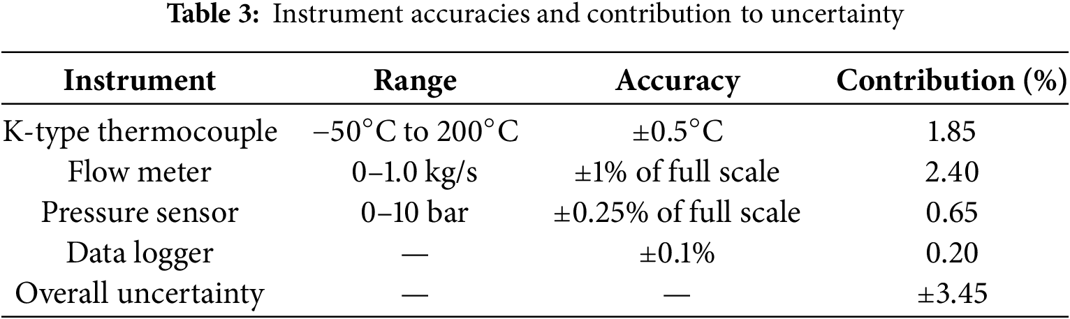
An uncertainty analysis was conducted using the propagation of error equations, incorporating instrumental precision to determine the reliability of the measured results. The uncertainty in the thermal efficiency was determined to validate the experimental consistency.
Derivation of Uncertainty
In experimental studies, all the measured quantities (temperature, flow rate, pressure, etc.) have inherent errors. To estimate the reliability of the calculated results, as shown in Table 3, the propagation of uncertainty McClintock methods.
where:
• R = result (e.g., heat transfer rate, efficiency).
• x1, x2, … = independent measured variables.
• where δxi is the uncertainty of each measured variable.
• δR = resulting uncertainty in R.
Application in This Study
• Measured parameters: water inlet/outlet temperature, mass flow rate, and time.
• Calculated parameter: Heat transfer rate (Q)
Applying uncertainty propagation:
If flow rate measurement has ±2% error,
• thermocouple accuracy is ±0.5°C,
• specific heat is assumed constant (negligible error).
The combined uncertainty in Q can then be quantified and reported (e.g., ±3.5%).
Reynolds Number Calculation
The Reynolds number (Re) is defined as:
where:
• ρ = fluid density (kg/m3)
• v = average velocity of fluid (m/s)
• Dh = hydraulic diameter of the tube/coil (m)
• μ = dynamic viscosity of the fluid (Pa·s)
For a circular tube,
where:
•
• D = inner diameter of the tube (m)
Thus:
Assume:
• Mass flow rate of water:
• Tube inner diameter: D = 0.01 m
• Water density: ρ = 998 kg/m3 (at ~25°C)
• Viscosity: μ = 0.001 Pa·s
Re = 4(0.05)/π(0.01)(0.001) ≈ 6366
Economics and Environmental Study
The amount of energy in terms of heat can be recovered by the spiral-coil heat exchanger and is calculated using the following equation:
where
Similarly, the amount of electrical energy produced by the heat exchanger is estimated as follows:
For a month the amount of money saved by the system is
where
This combined thermal, economic, and environmental analysis confirmed the feasibility and cost-effectiveness of integrating a spiral-coil heat exchanger into HVAC systems for sustainable water-heating applications [30]. The monthly energy savings were computed based on the recovered thermal energy, assuming 75% conversion efficiency from the recovered heat to usable water heating energy. The corresponding cost savings, payback period, and carbon emission reduction (based on 0.47 kg CO2/kWh emission factor) were analysed to evaluate the system’s alignment with SDG 7 (Affordable and Clean Energy) and SDG 13 (Climate Action).
3 Experimental Investigation and Results
Air-conditioning systems release a significant amount of waste heat into the atmosphere, representing a lost opportunity for energy recovery. This study investigated a compact and non-intrusive spiral-coil heat exchanger designed to recover waste heat from the outdoor unit of a conventional split A.C. system. The heat exchanger, which was made of copper and shaped to match the condenser fan diameter, transferred heat from the hot discharged air to the water circulating through the coil. This investigation focused on evaluating the thermal performance of the system at five different water flow rates (0.028–0.052 kg/s). The measured key parameters included the outlet water temperature, heat transfer rate from air to water, convective heat transfer coefficient, heat loss, and overall thermal efficiency. Additionally, the economic benefits (energy savings and payback period) and environmental impacts (CO2 reduction) of the system were analysed. The findings aim to validate the viability of the system for energy-efficient water heating using air conditioner waste heat.
A spiral-coil heat exchanger was experimentally investigated under similar air outputs and ambient temperatures. In this study, water was used as the HTF. Hence, hot air from the heat exhaust (air conditioners) is continuously collected by the spiral-coil heat exchanger, and a small amount of hot air is exhausted to the atmosphere (absorbing the maximum heat from the air conditioner heat exhaust). Five HTF flow rates were considered to vary the performance of the spiral-coil heat exchanger. Experiments were conducted continuously for several days at various flow rates. Observed readings under similar ambient conditions were used to calculate the thermal performance parameters at each flow rate. Therefore, the assignments and results were observed at intervals of 60 min. Based on the observed water outlet temperature, the heat rates of air and water, heat loss, and efficiency of the system were calculated, and the results are discussed. The experiment began at 9:00 a.m. and ended at 4:00 p.m.
Outlet water temperature
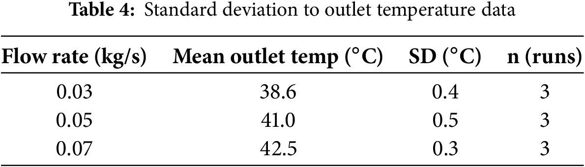
The water was allowed to flow through the spiral coil heat exchanger using an electric water pump, and the heated water was collected in the storage tank. Water was removed daily from the storage tank and filled again the following day. The spiral coil heat exchanger was connected to the pump at one end and the other was connected to the tank. The coil was made of copper; therefore, the heat transfer rate from air to water was higher. During the experiment, water flowed through the spiral coil without disturbing the tank. Hence, water receives a brief heat period from the coil (water takes more time to pass through the coil than water does) at each pass. The standard deviations of the outlet temperature data are listed in Table 4. Hence, the copper material also enhanced the heat-transfer rate. The outlet temperature of the water was measured at five different water flow rates of 0.028, 0.033, 0.036, 0.041, and 0.052 kg/s.
The outlet temperature of the water was approximately 67°C and was recorded at a flow rate of 0.052 kg/s, which is the maximum outlet temperature compared with the other flow rates. Similarly, for flow rates of 0.028, 0.033, 0.036, and 0.041 kg/s, the maximum outlet temperatures of the water were approximately 61°C, 63°C, 64°C, and 65°C, respectively. Fig. 5 shows the variation in water outlet temperature at various flow rates. This clearly indicates that increasing the water flow rate increased the outlet temperature of the water. Because of the lower flow rate, water has a lower velocity, giving more time to receive heat and reaching a higher temperature difference; however, the amount of water circulation is quite low. Increasing the water flow rate increases the number of water circulations passing through the coil. The maximum water temperature was observed at higher flow rates.
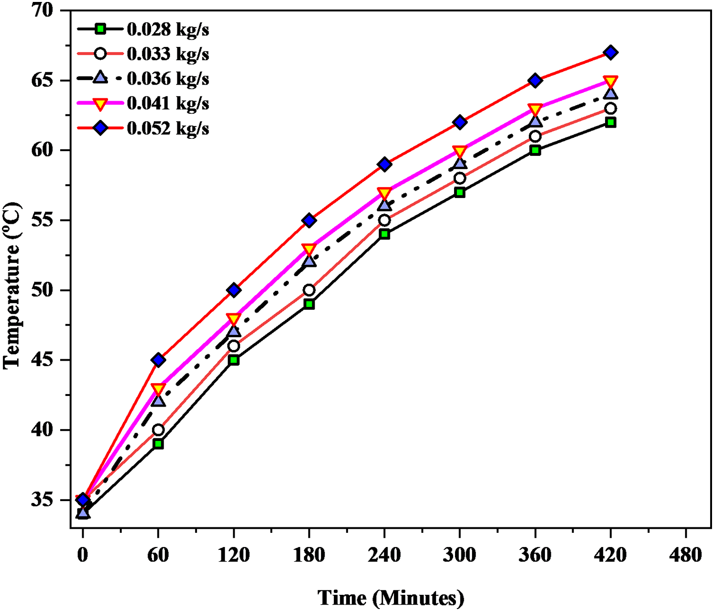
Figure 5: Temperature at various flowrate
Heat rate
The amount of heat transferred from air to water was calculated based on the water outlet temperature. The heat rate of the air was used as the input parameter. For a flow rate of 0.052 kg/s, the heat rate by air was approximately 1120 W, as shown in Fig. 6, which is the maximum heat rate by air compared with the other flow rates. The maximum heat rates of air recorded at the flow rates of 0.028, 0.033, 0.036, and 0.041 kg/s were approximately 910.2, 950.4, 1021, and 1065 W, respectively. Similarly, the heat rate of water was calculated using the following equation. Hence, the amount of heat generated by the water was fully based on the temperature difference between the inlet and outlet water temperatures. The maximum heat rates of water were approximately 758, 789, 905, 956, and 1020 kg/s and were recorded at flow rates of 0.028, 0.033, 0.036, 0.041, and 0.052 kg/s, respectively. The maximum heat rate was recorded at a flow rate of 0.052 kg/s, compared to the other flow rates. Fig. 7 shows that increasing the flow rate of water increased the heat transfer rate.

Figure 6: Heat rate curves obtained at the pressure rate of 0.5 kg/cm2
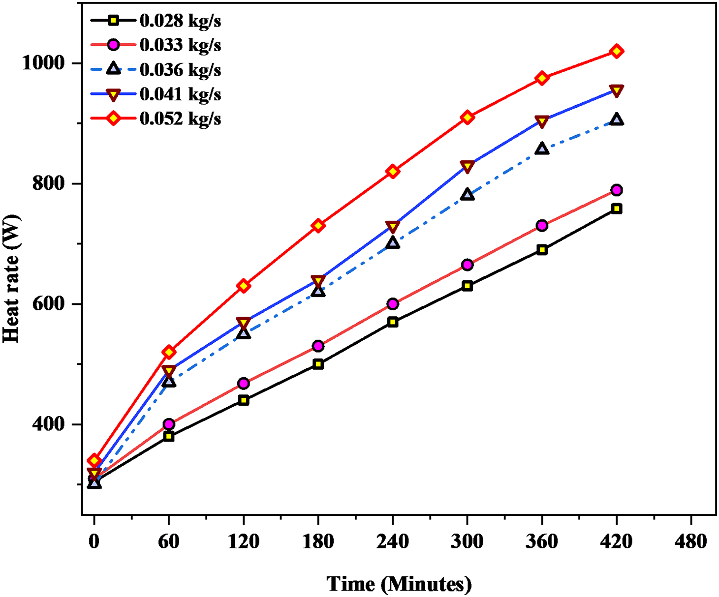
Figure 7: Heat rate curves obtained at the pressure rate of 1 kg/cm2
Heat transfer coefficient
The convective heat-transfer coefficient was calculated based on the heat gain of the HTF. Compared to the other flow rates, the maximum heat transfer coefficient was approximately 103.54 W/m2 K, which was recorded at a flow rate of 0.052 kg/s. At the flow rate of 0.028, 0.033, 0.036, and 0.041 kg/s, the maximum heat transfer coefficient is about 77.5, 78.9, 91.3, and 96.7 W/m2 K, respectively. Fig. 8 clearly demonstrates that the convective heat transfer coefficient of the HTF was fully dependent on the amount of heat transfer. Moreover, the heat-transfer coefficient increased with the HTF flow rate. Initially, at a flow rate of 0.028 kg/s, the heat-transfer coefficient of the HTF was almost the same because there was little difference between the inlet and outlet temperatures. Hence, CHTC was measured for this analysis to improve the efficiency of the SCHE.

Figure 8: Convective heat transfer efficiency
Heat loss
Fig. 9 shows the heat loss from the spiral coil heat exchanger under atmospheric conditions. The maximum heat loss occurred at a lower flow rate. At a flow rate of 0.028 kg/s, the maximum heat loss is approximately 250 W. In the experimental investigation, heat loss decreased with increasing time. At a flow rate of 0.052 kg/s, the heat loss was approximately 100 W, which was the lowest heat loss from the spiral-coil heat exchanger. Hence, increasing the mass flow rate decreases the heat loss from the heat recovery system.
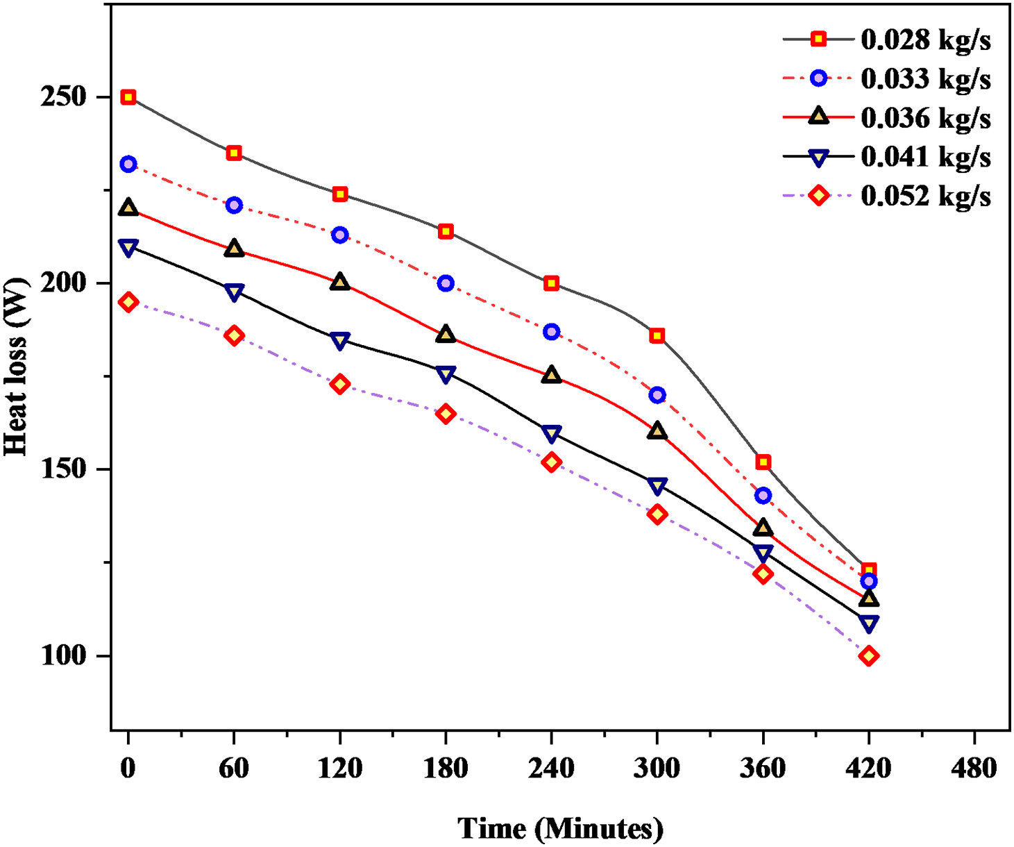
Figure 9: Heat loss curves
Efficiency
The efficiency of the spiral-coil heat exchanger was calculated using the heat-transfer rate. The average efficiency of the spiral-coil heat exchanger at various water flow rates is shown in the Fig. 10. The selected spiral-coil heat exchanger causes the fluid to flow in a circular spiral, increasing the travel time of water and enabling more surface contact with the copper coil. A higher amount of heat can be transferred from air to water. The average thermal efficiency is approximately 66.3% at a flow rate of 0.052 kg/s. which is the maximum efficiency value compared with the other flow rates. The efficiency of the heat exchanger increased with an increase in heat transfer. The efficiency of the heat exchanger was approximately 91.07%, and it was recorded at a flow rate of 0.052 kg/s. which is the maximum efficiency compared with the other flow rates. Fig. 11 shows that the efficiency of the heat exchange rate increases with increasing heat transfer. The efficiency was recorded during the initial stage at a flow rate of 62.3%. The efficiency of the heat exchanger also depends on the difference between the inlet and outlet temperatures of the water [effect of charging]. An improved heat absorption was observed at higher flow rates.

Figure 10: Efficiency of heat exchanger at different flow rate

Figure 11: Efficiency at different flow rate
At flow rates of 0.028, 0.033, 0.036, and 0.041 kg/s, the average efficiencies of the system were approximately 48.5%, 53.11%, 57.4%, and 59.61%, respectively. Lower mass flow rates resulted in lower thermal efficiencies than higher flow rates. The increased mass flow rate increased the thermal efficiency because of the higher useful heat absorption by water.
Hence, a higher flow rate increases the amount of water circulation; hence, a greater amount of heat is transferred to the water [enhancement of the thermal]. As the mass flow rate of water increased, a higher volume of water absorbed heat from the coil. Although water flows quickly at higher flow rates, more water absorbs more heat with less heat loss, resulting in enhanced efficiency of the collector. In addition, the useful energy absorbed by water is enhanced owing to the increased travel length of water through the copper coil, owing to the presence of the spiral-coil heat exchanger.
Economic and environmental analysis
The proposed spiral-coil heat exchanger systems were evaluated economically and environmentally under different conditions to estimate the cost savings, payback period, and carbon dioxide (CO2) reduction quantity. The amount of heat energy recovered using this type of spiral-coil heat exchanger is determined by the heat transfer rate of the water. The amount of electric energy

Figure 12: Energy saved vs flow rate
At a flow rate of 0.052 kg/s, the energy saved by the system was approximately 178.35 kWh/month was recorded, which was the maximum amount of energy saved by the system compared with the other flow rates. Simultaneously, the amount of money saved based on the energy savings was approximately 3745.35 Rs/month was estimated. Similarly, 128.19, 134.7, 155.46, and 163.23 kWh/month of energy saved at the flow rate of 0.028, 0.033, 0.036, and 0.041 kg/s.
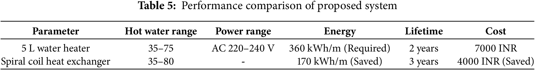
Fig. 13 clearly shows that increasing the mass flow rate of the water increased the energy savings when using the spiral-coil heat exchanger. This means that the system is more cost-effective at a higher flow rate and can economize more electric energy, which will directly affect the amount of money saved, payback period, and amount of carbon dioxide gas reduced. At flow rates of 0.028, 0.033, 0.036, and 0.041 kg/s, the money savings were approximately 2691, 2829, 3264, and 3427 Rs/month, respectively. It should be noted that the system operated at a low flow rate, and as the flow rate increased, the money saved increased. This means that, if the system is allowed to operate at a higher flow rate, more money is expected to be saved. The commercial water heaters utilized to obtain hot water available on the market were compared with the current spiral-coil heat exchanger, as shown in Table 5.

Figure 13: Payback period
To evaluate the recovery system’s payback period, the overall system cost must be estimated. The system is composed of a heat exchanger, duct, and pipes, with a total cost of Rs 18,000, including the installation cost and fabrication. It shows that the duration of the payback is highly affected by the flow rates. The figure clearly shows that the increasing flow rate lowers the payback period of the system. At the flow rate of 0.052 kg/s the payback period the heat exchanger is about 1.06 years. It’s the lowest payback period compared with other flow rates. The system can pay for itself after 1.06 years when it is used 24 h per day at 0.052 kg/s flow rate. This duration is less than the lifespan of an air conditioner.
Finally, with respect to environmental concerns, the quantity of CO2 gas reduced was calculated for the spiral coil heat exchanger, where mg is the quantity of carbon dioxide produced per kW/hr of electricity generated. Based on Lebanese studies, the amount of CO2 generated is 0.47 kg/kWh [16].
At a 0.052 kg/s flow rate, the system up to 187.26 kg/month of CO2, which is the maximum amount of CO2 reduction by the system compared with the other flow rates. Similarly, at flow rates of 0.028, 0.033, 0.036, and 0.041 kg/s, the amount of CO2 reduction were approximately 134.5, 141.4, 163.4, and 171.3 kg/month recorded, respectively.
However, it should be noted that the system reduces emissions more because this study is based on the electric energy of air conditioners, whereas more electric energy should be generated at an electric power plant to cover the losses through the grid lines. Because hot air from an air conditioner is allowed to move at a low flow rate, the money saved, payback period, and CO2 quantity reduction are relatively low. However, these results indicate a very promising system when operated at higher flow rates, allowing for greater energy recovery and CO2 reduction.
Optimization of pressure
The optimization of the pressure in thermal systems is critical for enhancing the heat transfer efficiency and ensuring stable system performance. In heat exchangers and fluid circuits, maintaining optimal pressure levels maximizes the fluid velocity, improves convective heat transfer, and minimizes energy losses. Excessive pressure can lead to mechanical stress and leakage, whereas insufficient pressure can result in a poor flow and reduced heat absorption. In waste heat recovery systems, particularly those involving spiral coil absorbers, pressure optimization ensures uniform water distribution and effective thermal exchange. The careful control of the pump output and pressure regulation enhances the overall system efficiency, reliability, and energy savings in HVAC-integrated applications. Three different pressures (0.5, 1, and 2 kg/cm2) were used at different times for different sensors (T1, T2, T3, and T4). The key goal is to identify the pressure setting that allows for the most efficient and uniform heat absorption without significant instability or overly rapid increases, which could indicate inefficiencies or potential system stress.
The experimental results in Table 6 show how different pressure settings—0.5, 1, and 2 kg/cm2—affect the temperature rise at various key locations in the heat recovery system: at the inlet (T1), centre of the spiral absorber (T2), outlet (T3), and inside the water tank (T4). At 0.5 kg/cm2, a moderate and stable increase in temperature was observed across all the sensors, with the most notable increase occurring inside the water tank (T4), where the temperature increased by approximately 60.7%. The average percentage increase across all the thermocouples at this pressure was approximately 27.2%, indicating effective heat absorption and system stability. At 1 kg/cm2, the system exhibited the highest average temperature increase (approximately 33%) across all measurement points, with significant gains at both the inlet and outlet, suggesting an efficient heat pickup and transfer through the spiral coil. This pressure setting provided the best overall balance between flow rate and heat transfer efficiency, making it the optimal pressure for uniform and effective thermal energy absorption. In contrast, at 2 kg/cm2, the temperature increase was less consistent and generally lower, particularly at the absorber centre (T2) and in the water tank (T4), where the percentage increases were only 2.4% and 29.4%, respectively. This indicates that a higher pressure may have led to a reduced residence time of water in the absorber, resulting in a decreased heat absorption efficiency.

Overall, the 1 kg/cm2 pressure condition yielded the most favourable thermal performance, offering a combination of high heat absorption, system stability, and energy transfer efficiency, whereas 0.5 kg/cm2 offered good tank heating with slower and more stable gains, and 2 kg/cm2 showed signs of inefficiency, possibly due to flow imbalance or thermal bypassing. Operating within the optimal pressure range is essential for maximizing thermal energy extraction while maintaining the overall system efficiency. Exceeding this range can result in diminishing returns, higher energy consumption, and potential mechanical strain in the system. To sustain optimal performance, it is crucial to continuously monitor both temperature and pressure levels and adjust them as necessary to remain within the ideal operating window. Enhancing the design and material selection of heat exchange surfaces favouring high-thermal-conductivity materials, such as copper, can further improve the heat transfer efficiency. Additionally, ensuring a uniform flow distribution of the working fluid throughout the system helps prevent localized overheating or performance inconsistencies, thereby contributing to more stable and effective heat recovery.
An experimental investigation was conducted to assess the feasibility and performance of a spiral-coil heat exchanger system for recovering waste heat from an air conditioner to heat water. The system was tested at five different water flow rates ranging from 0.028 to 0.052 kg/s, and various thermal and economic performance parameters were analysed.
The outlet water temperature directly reflects the heat-absorption capacity of the system. results revealed that higher flow rates resulted in higher outlet water temperatures, reaching a maximum of 67°C at 0.052 kg/s. Although lower flow rates allowed the water to remain in the coil longer, the reduced circulation volume limited the total heat gain. Thus, increasing the flow rate enhanced both the volume of heated water and the total energy absorbed. The heat transfer rate from air to water also exhibited a positive correlation with the flow rate. The maximum air-to-water heat transfer occurred at 0.052 kg/s, reaching 1120 W (air) and 1020 W (water). The increased heat rate at higher flow rates was attributed to the improved thermal contact and reduced heat loss to the surroundings owing to shorter residence times and higher turbulence within the coil.
The convective heat transfer coefficient (CHTC), a critical factor for efficient energy exchange, also increased with flow rate. The highest CHTC of 103.54 W/m2·K was observed at 0.052 kg/s, indicating that more turbulent flow enhances heat transfer by disrupting the thermal boundary layer along the copper surface. The thermal efficiency improved progressively with increasing flow rate, peaking at 91.07% at the maximum tested flow. This demonstrates that higher mass flow rates increase the effective use of the available heat, reduce thermal losses, and promote system reliability. Optimization of the operating pressure also played a role: a moderate pressure (1 kg/cm2) ensured a balanced flow and maximum heat extraction without overloading the system. Pressures below 0.5 kg/cm2 showed inefficient performance owing to insufficient water movement, whereas 2 kg/cm2 reduced the residence time and marginally affected the heat gain.
The spiral coil design further enhanced the performance by increasing the water travel length and ensuring prolonged exposure to a hot air stream. This design avoids any structural disturbances in the air-conditioning system, which is a unique aspect of this study. The copper material, with its high thermal conductivity (370 W/m·K), significantly boosted heat transfer, contributing to the high efficiency of the system. An uncertainty analysis was performed to validate the accuracy of the temperature-based calculations, because the heat rate and efficiency depend heavily on precise readings. The combined uncertainty for the thermal efficiency was estimated to be ±3.45%, which is within the acceptable limits for experimental thermal systems and ensures the reliability of the derived performance metrics.
In terms of economics, the system demonstrated strong potential for monthly energy savings, especially at higher flow rates. At 0.052 kg/s, the system saved 178.35 kWh/month, translating to approximately ₹3745.35/month in electricity cost savings. Lower flow rates yielded lesser savings but still presented significant reductions in energy bills. Compared to a conventional 5 L electric water heater that consumes approximately 360 kWh/month, the spiral heat exchanger reduced dependency on grid electricity, saving up to 170 kWh/month, and offered a payback period of just 1.06 years—well within the expected lifespan of an A.C. system. Thus, the proposed system is a cost-effective alternative to the commercial water heaters.
Environmentally, the system contributes to reduce carbon emissions by lowering electricity demand. At the optimal flow rate, the system helped to reduce up to 187.26 kg/month of CO2 based on an emissions factor to 0.47 kg CO2 per kWh. These reductions are particularly significant in regions in which power generation relies on fossil fuels.
4.1 Comparative Analysis with Electric Water Heaters
The spiral coil heat exchanger offers several advantages over conventional electric water heaters:
• Lower operational cost, due to energy recovery rather than grid consumption.
• No additional power requirement, as it utilizes waste heat.
• Higher thermal efficiency and sustainability.
• Shorter payback period and reduced CO2 emissions.
Although commercial heaters provide direct, on-demand heating, they result in higher electricity consumption and environmental impact. In contrast, the spiral heat exchanger, although dependent on A.C. operation, is highly efficient when integrated into daily use during warm seasons.
4.2 Electricity Tariffs in the Region
According to the Central Electricity Authority (CEA), India, and regional State Electricity Boards (SEBs) (domestic consumer slabs, 2024–25),
• Typical domestic tariff: ₹5.5–₹8.0 per kWh
• Typical commercial tariff: ₹8.0–₹11.0 per kWh
• National average (domestic, urban households): ~₹6.5/kWh
4.3 Electricity Savings by Waste Heat Recovery (Example)
If the WHR system reduces geyser (water heater) electricity consumption by heating 50 L/day of water to 45°C, then
• Energy needed without WHR:
Q = 50 × 4.186 × (45 − 30) ≈ 3139 kJ ≈ 0.87 kWh/day
• Annual savings:
0.87 kWh/day × 365 ≈ 318 kWh/year
Cost savings (domestic rate ~₹6.5/kWh):
318 × 6.5 ≈ ₹2067 per year
4.4 The Impact of Large-Scale Deployment across Urban Areas
Using India-specific data (urban population, household size, AC penetration) and a conservative per-household WHR yield of 318 kWh/year and estimated that retrofitting 10%–60% of existing urban room ACs (≈14.8 M AC-equipped households total) would save 0.472–2.832 TWh/year, avoid 0.34–2.06 MtCO2/year (grid EF = 0.727 kg CO2/kWh), and save between ≈₹307–₹1840 crore annually at a representative tariff of ₹6.5/kWh.
4.5 Field-Scale or Practical Retrofit Case Studies
Setup: A 1.5-Tonne split AC (commonly used in Indian households) was retrofitted using a spiral-coil waste heat recovery (SCHE) system. Operation: The AC runs for approximately 6 h/day during the summer. WHR unit heats ~50 L of water daily from 28°C to 45°C.
Performance:
• Energy saved: ~318 kWh/year (equivalent to the daily heating load of a geyser).
• Cost saving: ~₹2000/year (tariff ~₹6.5/kWh).
• CO2 reduction: ~260 kg/year (grid emission factor: 0.727 kg CO2/kWh).
Outcome: This study demonstrates that WHR can substitute household geysers in moderate-demand homes.
4.6 Compare CO2 Savings with Other Water Heating Systems
Using a conservative per-household WHR yield of 318 kWh/yr and CEA grid factor (0.727 kg CO2/kWh), WHR retrofits can substantially reduce household water-heating emissions compared to conventional electric resistance or LPG heaters—approximately 205 kg CO2/yr saved versus an electric geyser and ~71 kg CO2/yr versus LPG. The WHR also outperforms a COP ≈ 3 electric heat pump by ~51 kg CO2/yr under the current grid intensity. However, solar thermal systems (flat-plate or evacuated-tube) have much lower life-cycle emissions (order 10–50 g CO2/kWh) and therefore typically outperform WHR on CO2 per useful kWh. WHR and solar energy can be complementary (WHR supplies heat when AC runs; solar energy covers daytime demand).
The estimated cradle-to-gate embodied emissions for the WHR unit by summing material masses multiplied by material emission factors from the ICE and Circular-Ecology databases (copper: 4.1 kg CO2/kg; steel: 1.8 kg CO2/kg; plastics: 2.5 kg CO2/kg) and annualizing the total over an expected service life of 10 years. For a representative unit (3 kg copper coil, 8 kg steel tank, pump, insulation, and controls), the embodied emissions were ≈36 kg CO2 (cradle-to-gate) or ≈3.6 kg CO2/yr when amortized. This is smaller than the annual operational CO2 savings (~205 kg CO2/yr versus an electric-resistance geyser), demonstrating that a WHR retrofit yields net lifecycle benefits. The results were sensitive to the copper production route and the device lifetime, and a sensitivity analysis of ±30% was performed.
4.7 Sensitivity Analysis for Part-Time A/C Operation
A sensitivity analysis was performed to evaluate the WHR performance when the AC operated part-time. The recoverable heat was scaled by the AC operation fraction and matching efficiency (the fraction of hot water demand coincident with condenser heat availability). Assuming 318 kWh/yr recoverable at full availability and 36.5 kWh/yr parasitic power (both scaled linearly), net annual household savings range from near-zero for low matching and short AC operation to >280 kWh/yr when the AC runs continuously and timing is ideal. This analysis highlights the importance of system design (timing, storage, or hybridization) in effectively capturing available waste heat.
This study successfully demonstrated that a spiral-coil heat exchanger, when attached externally to an air-conditioned outdoor unit, can effectively capture and utilize waste heat to produce hot water. The performance improved at higher water flow rates, exhibiting enhanced outlet temperatures, heat-transfer rates, and efficiency. The system design, operating pressure, and material selection all contribute to the superior thermal performance without affecting the A.C. system. Economic and environmental benefits underscore the practicality and sustainability of this approach. Compared to traditional electric water heaters, this system offers better efficiency, faster return on investment, and a lower carbon footprint. The results clearly support the potential of integrating waste heat recovery systems into HVAC applications for energy saving and environmental conservation.
This study successfully demonstrated the design, development, and experimental validation of a non-intrusive spiral-coil heat exchanger for recovering waste heat from HVAC condenser units. The system operates externally, preserving the original configuration of the air-conditioning unit, while enhancing its overall energy efficiency. This makes it ideal for new installation and retrofitting applications, particularly in energy-intensive urban environments.
Experimental results confirmed that increasing the water flow rate enhanced thermal performance, with the highest efficiency of 91.07% and outlet temperature of 67°C observed at 0.052 kg/s. The convective heat transfer coefficient and overall heat absorption increased with the flow rate, whereas the heat losses decreased, thereby demonstrating the effectiveness of the design under high-throughput conditions. Optimal thermal performance was achieved at 1.0 kg/cm2, balancing the flow uniformity with effective heat transfer.
Economically, the system yielded substantial benefits—achieving 178.35 kWh/month of energy savings, ₹3745.35/month in cost reduction, and a payback period of just 1.06 years. Environmentally, it has reduced up to 187.26 kg/month of CO2 emissions, highlighting its potential to meaningfully contribute to climate mitigation efforts.
By transforming waste heat into a valuable resource, the proposed system supports the global sustainability goals, particularly SDG 7 (clean energy), SDG 9 (industrial innovation), and SDG 13 (climate action). Future work may involve integration with thermal storage systems using phase change materials (PCMs) to extend their usability beyond air conditioner operation periods. This study establishes a cost-effective, scalable, and sustainable solution to improve building energy efficiency and reduce the environmental impact.
Future scope:
The present study establishes the potential of utilizing air conditioner condenser waste heat for water heating, but several opportunities remain for further research and large-scale adoption. Hybridization with solar water heaters or photovoltaic-assisted systems can provide continuous hot water availability, where solar systems supply energy during the day, while waste heat recovery (WHR) serves as a backup during non-solar hours, enhancing the year-round efficiency. Incorporating phase change materials (PCMs) around storage tanks, particularly with melting points between 45°C–60°C, can store surplus heat during peak AC operation and release it later, thereby bridging the gap between heat availability and demand. Additionally, intelligent controllers can be developed to monitor the AC operation, water consumption, and solar input to optimize the switching between WHR, thermal storage, and auxiliary heating. On a larger scale, integration into community hot-water networks in residential or commercial complexes can maximize energy and CO2 savings. Furthermore, a detailed life-cycle assessment that considers cost, reliability, and embodied energy will support sustainable policy adoption.
Acknowledgement: The authors would like to thank the SRM Institute of Science and Technology, Kattankulathur, for providing the facilities and support for the experimental work.
Funding Statement: Not applicable.
Author Contributions: S. Srinivasa Senthil: Conceptualization, Methodology, Development of model, Simulation, Experimental work, Data generation, Writing—original draft preparation. K. Vijayakumar: Conceptualisation, Model development, Writing—review & editing, Supervision. All authors reviewed the results and approved the final version of the manuscript.
Availability of Data and Materials: The study contains private data.
Ethics Approval: Not applicable.
Conflicts of Interest: The authors declare no conflicts of interest nor competing interests.
Glossary
| Symbol | Description | Unit |
| Q | Heat transfer rate | W |
| Qrec | Recovered heat energy | kWh or J |
| ΔT | Temperature difference | °C |
| Tin, Tout | Inlet and outlet water temperatures | °C |
| Tair | Condenser outlet air temperature | °C |
| Mass flow rate | kg/s | |
| Water mass flow rate | kg/s | |
| Cp | Specific heat capacity | J/kg·K |
| U | Overall heat transfer coefficient | W/m2·K |
| A | Heat transfer area | m2 |
| Re | Reynolds number | – |
| Nu | Nusselt number | – |
| Pr | Prandtl number | – |
| K | Thermal conductivity | W/m·K |
| Hsys | System efficiency | – |
| Hmatch | Demand–supply matching efficiency | – |
| fAC | AC operation fraction | – |
| Pparasitic | Parasitic power (pump, controls) | W |
| Efull | Annual recoverable energy (at full AC availability) | kWh/year |
| CO2 | Carbon dioxide emission | kg |
| EF | Emission factor | kg CO2/kWh |
| ΔE | Net energy saved | kWh |
| CI | Confidence interval | – |
| SD | Standard deviation | – |
References
1. Hammond GP, Norman JB. Heat recovery opportunities in UK industry. Appl Energy. 2014;116:387–97. doi:10.1016/j.apenergy.2013.11.008. [Google Scholar] [CrossRef]
2. Mahmoudinezhad S, Sadi M, Ghiasirad H, Arabkoohsar A. A comprehensive review on the current technologies and recent developments in high-temperature heat exchangers. Renew Sustain Energy Rev. 2023;183(2023):113467. doi:10.1016/j.rser.2023.113467. [Google Scholar] [CrossRef]
3. Jouhara H, Khordehgah N, Almahmoud S, Delpech B, Chauhan A, Tassou SA. Waste heat recovery technologies and applications. Therm Sci Eng Prog. 2018;6(1):268–89. doi:10.1016/j.tsep.2018.04.017. [Google Scholar] [CrossRef]
4. Schall D, Hirzel S. Thermal cooling using low-temperature waste heat: a cost-effective way for industrial companies to improve energy efficiency? Energy Effic. 2012;5(4):547–69. doi:10.1007/s12053-012-9151-0. [Google Scholar] [CrossRef]
5. Chai KH, Yeo C. Overcoming energy efficiency barriers through systems approach—a conceptual framework. Energy Policy. 2012;46(2):460–72. doi:10.1016/j.enpol.2012.04.012. [Google Scholar] [CrossRef]
6. Chowdhury JI, Hu Y, Haltas I, Balta-Ozkan N, Matthew GJ, Varga L. Reducing industrial energy demand in the UK: a review of energy efficiency technologies and energy saving potential in selected sectors. Renew Sustain Energy Rev. 2018;94:1153–78. doi:10.1016/j.rser.2018.06.040. [Google Scholar] [CrossRef]
7. Ahmed HM. The amount of fresh water wasted as by product of air conditioning systems: case study in the Kingdom of Bahrain. In: Proceedings of the International Conference on Fourth Industrial Revolution (ICFIR); 2019 Oct 28–30; Qingdao, China. p. 1–4. doi:10.1109/ICFIR.2019.8894782. [Google Scholar] [CrossRef]
8. Aziz MB, Zain ZM, Baki SR, Hadi RA. Air-conditioning energy consumption of an education building and it’s building energy index: a case study in engineering complex, UiTM Shah Alam, Selangor. In: Proceedings of the 2012 IEEE Control and System Graduate Research Colloquium; 2012 Jul 16–17; Shah Alam, Malaysia. p. 175–80. doi:10.1109/ICSGRC.2012.6287157. [Google Scholar] [CrossRef]
9. Bansal P, Vineyard E, Abdelaziz O. Status of not-in-kind refrigeration technologies for household space conditioning, water heating and food refrigeration. Int J Sustain Built Environ. 2012;1(1):85–101. doi:10.1016/j.ijsbe.2012.07.003. [Google Scholar] [CrossRef]
10. Cai J, Yu W, Xu W, Wang K. Research on air-conditioning operation energy saving in internet data center. In: Proceedings of the 8th International Conference on Hydraulic and Civil Engineering: Deep Space Intelligent Development and Utilization Forum (ICHCE); 2022 Nov 25–27; Xi’an, China. p. 1273–6. doi:10.1109/ICHCE57331.2022.10042623. [Google Scholar] [CrossRef]
11. Cheng L, Xia G. Progress and prospects for research and technology development of supercritical CO2 thermal conversion systems for power, energy storage, and waste heat recovery. Heat Transf Eng. 2024;45(20–21):1836–53. doi:10.1080/01457632.2023.2282765. [Google Scholar] [CrossRef]
12. Cheng X, Yin Y, Che C, Ji Q, Cao B, Chen W. Experimental and simulation study on an air conditioning system cascade driven by waste heat using multicomponent solution. Build Environ. 2024;247(3):111021. doi:10.1016/j.buildenv.2023.111021. [Google Scholar] [CrossRef]
13. Deshpande AC, Pillai RM. Adsorption air-conditioning (AdAC) for automobiles using waste heat recovered from exhaust gases. In: Proceedings of the 2009 Second International Conference on Emerging Trends in Engineering & Technology; 2009 Dec 16–18; Nagpur, India. p. 19–24. doi:10.1109/ICETET.2009.22. [Google Scholar] [CrossRef]
14. Kalukhe SK, Patil DY, Ugale E. Experimental study and CFD analysis of heat recovery system for window air conditioning. In: Proceedings of the 2016 International Conference on Energy Efficient Technologies for Sustainability (ICEETS); 2016 Apr 7–8; Nagercoil, India. p. 841–4. doi:10.1109/ICEETS.2016.7583863. [Google Scholar] [CrossRef]
15. Liu J, Yu B. Research on thermal environment in room using separated air-conditioning unit by supplying low-temperature air. In: Proceedings of the 2010 International Conference on Networking and Digital Society; 2010 May 30–31; Wenzhou, China. p. 180–5. doi:10.1109/ICNDS.2010.5479336. [Google Scholar] [CrossRef]
16. Lokapure RB, Joshi JD. Waste heat recovery through air conditioning system. Int J Eng Res Dev. 2012;5(3):87–92. [Google Scholar]
17. Long J. Research on control method of intelligent air-conditioning system in smart city. In: Proceedings of the 2020 International Conference on Intelligent Transportation, Big Data & Smart City (ICITBS); 2020 Jan 11–12; Vientiane, Laos. p. 787–90. doi:10.1109/ICITBS49701.2020.00172. [Google Scholar] [CrossRef]
18. Mathur G. Carbon dioxide as an alternative refrigerant for automotive air conditioning systems. In: Proceedings of the 35th Intersociety Energy Conversion Engineering Conference and Exhibit (IECEC); 2000 Jul 24–28; Las Vegas, NV, USA. p. 371–9. doi:10.1109/iecec.2000.870712. [Google Scholar] [CrossRef]
19. Ramyashree AP, Joel AD, Rakshith HS, Impha YD, Mahammad YC, Ajaygan K, et al. Heat recovery from air conditioner. J Mech Eng Autom. 2016;6(5):113–6. [Google Scholar]
20. Singh RK, Ahmad SN, Priyadarshi N, Rahman MO, Bhoi AK. Waste heat energy utilization in refrigeration and air-conditioning. IOP Conf Ser Mater Sci Eng. 2018;402(1):12060. doi:10.1088/1757-899X/402/1/012060. [Google Scholar] [CrossRef]
21. Shivam V, Rushikesh T, Nikesh T, Dhananjay W, Surekha K. A review of waste heat recovery from air conditioning system. Int J Eng Res Technol. 2022;11(4):152–7. [Google Scholar]
22. Yu W, Zhao Y, Wang K, Wu J. Research on water spray evaporative cooling air-conditioning system in public buildings. In: Proceedings of the 3rd International Academic Exchange Conference on Science and Technology Innovation (IAECST); 2021 Dec 10–12; Guangzhou, China. p. 2004–7. doi:10.1109/IAECST54258.2021.9695628. [Google Scholar] [CrossRef]
23. Vo K, Dang TA. A study on change of the shape and size of the minichannel evaporators to enhance the cooling capacity of the CO & underscore; 2 air conditioning cycle. In: Proceedings of the 4th International Conference on Green Technology and Sustainable Development (GTSD); 2018 Nov 23–24; Ho Chi Minh City, Vietnam. p. 404–8. doi:10.1109/GTSD.2018.8595693. [Google Scholar] [CrossRef]
24. Trushliakov E, Radchenko M, Radchenko A, Kantor S, Zongming Y. Statistical approach to improve the efficiency of air conditioning system performance in changeable climatic conditions. In: Proceedings of the 5th International Conference on Systems and Informatics (ICSAI); 2018 Nov 10–12; Nanjing, China. p. 256–60. doi:10.1109/ICSAI.2018.8599434. [Google Scholar] [CrossRef]
25. Rady M, Albatati F, Hegab A, Abuhabaya A, Attar A. Design and analysis of waste heat recovery from residential air conditioning units for cooling and pure water production. Int J Low-Carbon Technol. 2021;16(3):1018–32. doi:10.1093/ijlct/ctab033. [Google Scholar] [CrossRef]
26. Sabir S, Pant H, Kanojia N, Rawat K. Design for improvement of COP from waste heat utilization through air conditioning system. J Graph Era Univ. 2023;57–68. doi:10.13052/jgeu0975-1416.1115. [Google Scholar] [CrossRef]
27. Sivaram AR, Karuppasamy K, Rajavel R, Prasad BA. Experimental investigations on the performance of a water heater using waste heat from an air conditioning system. Indian J Sci Technol. 2015;8(36):1–6. doi:10.17485/ijst/2015/v8i36/88473. [Google Scholar] [CrossRef]
28. Widodo S, Rubianto G. Utilization of air conditioning heat waste as cloth drying energy source. J Energy Mech Mater Manuf Eng. 2021;6(1):59–66. doi:10.22219/jemmme.v6i1.12574. [Google Scholar] [CrossRef]
29. Wijewardane MA, Herath HMPD, Ranasinghe RACP. Reducing the excess energy consumption on higher ventilation flowrates to control the CO2 levels of the central air conditioning systems in polluted urban areas by CO2 capturing. In: Proceedings of the 2022 Moratuwa Engineering Research Conference (MERCon); 2022 Jul 27–29; Moratuwa, Sri Lanka. p. 1–5. doi:10.1109/MERCon55799.2022.9906229. [Google Scholar] [CrossRef]
30. Wiriyasart S, Kaewluan S. Waste heat recovery of air conditioning on thermal efficiency enhancement of water heater. Therm Sci Eng Prog. 2024;47:102296. doi:10.1016/j.tsep.2023.102296. [Google Scholar] [CrossRef]
Cite This Article
 Copyright © 2025 The Author(s). Published by Tech Science Press.
This work is licensed under a Creative Commons Attribution 4.0 International License , which permits unrestricted use, distribution, and reproduction in any medium, provided the original work is properly cited.
 Downloads
 Citation Tools