
 Submit a Paper
 Propose a Special lssue
 Open Access
ARTICLE

Value Assessment Method for the Grid-Alternative Energy Storage Based on Coordinated Planning Framework
1 State Grid Jibei Electric Power Company Limited Economic Research Institute, State Grid Jibei Electric Power Company Limited, Beijing, 100038, China
2 School of Electrical and Electronic Engineering, North China Electric Power University, Beijing, 102206, China
* Corresponding Author: Zili Chen. Email:
Energy Engineering 2025, 122(2), 621-649. https://doi.org/10.32604/ee.2025.056335
Received 20 July 2024; Accepted 30 October 2024; Issue published 31 January 2025
 View Full Text
 Download PDF
Abstract
As the development of new power systems accelerates and the impacts of high renewable energy integration and extreme weather intensify, grid-alternative energy storage is garnering increasing attention for its grid-interaction benefits and clear business models. Consequently, assessing the value of grid-alternative energy storage in the system transition has become critically important. Considering the performance characteristics of storage, we propose a value assessment frame-work for grid-alternative energy storage, quantifying its non-wires-alternative effects from both cost and benefit perspectives. Building on this, we developed a collaborative planning model for energy storage and transmission grids, aimed at maximizing the economic benefits of storage systems while balancing investment and operational costs. The model considers regional grid interconnections and their interactions with system operation. By participating in system operations, grid-alternative energy storage not only maximizes its own economic benefits but also generates social welfare transfer effects. Furthermore, based on multi-regional interconnected planning, grid-alternative energy storage can reduce system costs by approximately 35%, with the most significant changes observed in generation costs. Multi-regional coordinated planning significantly enhances the sys-tem’s flexibility in regulation. However, when the load factor of interconnection lines between regions remains constant, system operational flexibility tends to decrease, leading to a roughly 28.9% increase in storage investment. Additionally, under regional coordinated planning, the greater the disparity in wind power integration across interconnected regions, the more noticeable the reduction in system costs.Keywords
With the implementation of the “dual carbon” goals, new energy generation, particularly wind and solar power, have been widely adopted. The incorporation of a large share of new energy into the grid is considered a core feature and primary development trend of the modern power system [1,2]. However, as the scale of new energy integration continues to expand, the issue of new energy consumption between different provinces is becoming increasingly prominent. This problem is particularly evident among several provinces in the Northwest power grid. The abundant renewable resources in the Northwest region have led to severe curtailment of electricity. From the viewpoint of grid planning, this challenge stems from the swift growth in installed renewable capacity, while the development of large share new energy transmission infrastructure lags behind, resulting in significant disparities [3]. Additionally, with the advancement of multi-type energy collaborative development, the need for internal coordination within the energy system is continuously increasing. The lengthy construction timelines and substantial investment required for new transmission channels have limited grid capacity, resulting in congestion and wind power curtailment issues. Ultimately, this severely restricts the cross-regional absorption of renewable energy and the overall balance [4]. This situation not only affects the economy and stability of the power system but may also undermine effectiveness of the national energy transition strategy.
To address the absorption issues arising from large-scale new energy incorporation, the traditional solution in planning has been to construct transmission network structures that accommodate large-scale renewable energy integration [5]. On one hand, the inherent volatility and the unpredictability of new energy output complicates precise boundary definition conditions in grid planning, thereby affecting the reliability and effectiveness of the planning results. On the other hand, as the scale and complexity of the grid increase, traditional planning methods are proving inadequate in addressing the changing market demands and rapidly evolving technological environment. Therefore, new solutions need to be explored to enhance the flexibility and adaptability. A novel approach involves the implementation of grid-alternative energy storage (GAES), where energy storage systems are deployed to substitute or postpone grid enhancements, thus economically and flexibly enhancing power supply capabilities in areas with weak grids [6,7]. It can not only mitigate the risk of renewable energy curtailment but also offer a cushion for the uncertainty of renewable energy output. Additionally, the application of GAES can alleviate the pressure on local grids in dealing with extreme weather events and other emergencies, thereby enhancing the grid’s overall robustness.
Moreover, with the gradual opening of the energy market and the continuous improvement of the electricity trading mechanism, GAES can provide new profit models for market participants [8]. For example, through involvement in the electricity spot and ancillary services markets, or capacity market, GAES can flexibly respond to market price signals and achieve diversified revenue streams [9]. Additionally, GAES can be integrated with emerging technologies such as distributed energy and microgrids, promoting the transition of the energy system from centralized to distributed and intelligent, further enhancing the sustainability. The policy environment is also increasingly supportive of the development of GAES. In 2021, the National Development and Reform Commission and the National Energy Administration released the “Guiding Opinions on Accelerating New Energy Storage Development”, explicitly stating that the costs and benefits of GAES facilities will be included in the tariff recovery mechanism for transmission and distribution [10]. This policy direction provides solid institutional support for the adoption and promotion of storage technologies.
Additionally, in the context of large-scale new energy integration, balancing grid expansion with the strategic implementation of energy storage systems is crucial. This strategy not only enhances the absorption capacity of renewable energy but also improves the economic efficiency of the power system and optimizes the utilization of transmission infrastructure. The deployment of GAES can substantially decrease the demand for new transmission infrastructure, thus reducing costs and maximizing environmental benefits. Furthermore, GAES can strengthen grid resilience by offering ancillary services like frequency regulation and voltage support, which are crucial for sustaining grid stability amid renewable energy output fluctuations [11]. Moreover, the promotion of GAES can drive innovation in the energy market, enhancing the resilience and adaptability of the grid. Particularly in the face of increasing pressure from renewable energy integration, it is crucial to establish a comprehensive planning framework that effectively quantifies the value of grid-alternative energy storage and explores its potential role and impact in the future energy system transition.
1.2 Literature Review and Contributions
To tackle the integration challenges posed by large-scale renewable energy adoption, both academia and industry have extensively studied the non-line alternative role of energy storage [12]. Compared to investing in transmission lines, storage, as a core flexible and adjustable resource, has a relatively shorter construction cycle. When energy storage is jointly planned with the grid side and transmission network, it can postpone transmission line construction, boost renewable energy absorption capacity, and enhance the economic efficiency and flexibility of the power system [13,14]. Literature [15] comprehensively considers transmission line losses and the uncertainties of hurricane duration and repair time, constructing a coordinated planning model for energy hubs and mobile energy storage that accounts for demand response. It introduces the Expected Load Not Supplied (ELNS) metric to quantify the value potential of large industrial energy hubs (EH) and mobile storage in improving the resilience. Literature [16] incorporates wind farm regulation capabilities, combining multi-level error correction control models for storage and pumped storage systems with storage-transmission coordinated planning models, thereby improving the reliability of planning schemes. At the same time, energy storage can function as a non-wires alternative, substituting for traditional transmission expansion projects [17,18]. Literature [19] suggests a method to postpone new grid capacity construction by quantifying distributed resources, including energy storage. Literature [20] discusses the scale and scheduling methods for using battery energy storage systems as non-wires alternative solutions, exploring the load shifting capability of battery storage and its impact on transformer hot spot temperature, aging, and insulation life extension.
The aforementioned literature has made significant contributions to the research on coordinated planning models and optimization strategies for transmission infrastructure and storage solutions. It demonstrates that grid-alternative energy storage can more conveniently and economically delay or replace grid upgrades, serving as a substitute for transmission and distribution facilities. However, they have not systematically analyzed the value of grid-alternative energy storage, making it difficult to achieve cost recovery for storage. Due to market mechanism reforms and adjustments in energy policies, the potential value of grid-alternative energy storage systems is continuously increasing, necessitating a comprehensive evaluation of their economic and multidimensional value.
To fill the research gap mentioned above, many studies have considered the economic costs and additional benefits of energy storage in their planning models. These benefits include mitigating the volatility of renewable energy output, reducing grid line losses, and delaying grid line upgrades [21–23]. Literature [24] proposes two constraint-based iterative search algorithms to determine the optimal allocation of renewable energy installed capacity and energy storage capacity, balancing system economic benefits and operational reliability. However, the planning model constructed does not cover the heterogeneous factors affecting the optimal installed capacity of new energy and energy storage, nor does it consider the environmental benefits of coordinated operation between new energy and energy storage. Literature [25] introduces a new time clustering method that maintains the time sequence of input time series to evaluate the economic value of coordinated operation between renewable energy and energy storage. However, it does not reflect the low-carbon and safety values brought by the expansion of renewable energy and storage for operation. Literature [26] uses externality value theory to quantify the flexibility mechanism of energy storage, combining the cost pass-through mechanism of energy storage with the optimal allocation model of energy storage. It designs an incentive mechanism for system revenue sharing, which can eliminate social welfare transfers between different regions. This mechanism effectively promotes the advancement and implementation of grid-side energy storage. However, it does not conduct a quantitative analysis of the multidimensional value of energy storage.
Although the aforementioned studies have undertaken extensive research on mitigating the volatility of renewable energy output and quantitatively evaluated the economic costs and additional benefits of energy storage, most of these studies are according to the quantitative evaluation of the value of independent storage systems in specific scenarios. Furthermore, the majority of these analyses focus on the economic value of storage systems and do not deeply explore the multidimensional value of GAES in different scenarios.
To fully leverage the role of energy storage systems in enhancing new energy absorption, delaying grid upgrades, and reducing system carbon emissions, especially in terms of the quantitative development of storage’s value in ensuring power balance across time scales and meeting diverse energy demands, we maximize the value of energy storage systems through the joint planning and operation of multiple types of storage and new energy. The contributions are as follows:
1) Considering the performance attributes of different types of energy storage vary, we propose a quantitative evaluation framework based on the multidimensional value of GAES. This framework not only quantifies the nonlinear substitution effects of energy storage from both cost and benefit perspectives but also delves into the direct and indirect benefits of energy storage. These include the direct economic value brought by peak-valley arbitrage and ancillary service revenues, along with the security value of storage on the grid side, renewable energy sources, and conventional power sources. It reveals the multidimensional value of GAES for different types, paving the way for the design of subsequent coordinated planning models for energy storage and transmission networks.
2) To further quantify the multidimensional system value of GAES, this paper constructs a coordinated planning model suitable for energy storage and transmission networks. The model aims to assess the substitution value of energy storage in the grid by taking the difference between the multidimensional benefits and costs of GAES as the optimization goal. The model comprehensively considers the differences in output characteristics between the power sending and receiving ends of the system, as well as the coordinated operation constraints of the source-grid-storage system. To accelerate the solving process, we propose an adaptive clustering algorithm during the model-solving process, which reasonably divides the long-term operation sequences of the system, effectively balancing the efficiency and accuracy of solving the planning model. By quickly solving the optimization planning results under different typical scenarios, we conduct an in-depth analysis and quantitative study of the intrinsic correlation between different boundaries, planning results, and the multidimensional value of energy storage.
3) Based on actual datasets, we verify the feasibility of integrating the advantages of GAES into the joint planning model of storage and transmission grid. The results show that the system’s comprehensive value brought by grid-substituted energy storage varies for different stakeholders. On this basis, we further explore the impact of multi-regional coordinated interconnection and different interconnection operation modes on the multidimensional system value of GAES. Under the consideration of multi-regional coordinated interconnection planning, GAES can significantly reduce the wind and solar curtailment, enhance cost-effectiveness of system planning and operation, and reduce system costs by nearly 50%. Additionally, multi-regional integrated energy storage significantly enhances system flexibility, thereby reducing the frequency of generator start-up and shutdown operations, with system unit start-stop costs decreasing by approximately 14%. Furthermore, when the load factor of interregional interconnection lines remains constant, system operational flexibility decreases, leading to an increase in energy storage investment costs by approximately 29%. Moreover, the greater the difference in wind power grid integration scales between interconnected regions, the more significant the reduction in system costs.
2 Framework for the Value Assessment of Grid-Alternative Energy Storage
In coordinating transmission networks and storage, energy storage can participate in peak-valley arbitrage while also generating indirect benefits by deferring transmission line upgrades, boosting renewable energy integration, and optimizing equipment utilization. This paper, therefore, characterizes energy storage that delays transmission expansion, enhances renewable capacity, and improves equipment use within the integrated framework of transmission and storage as a grid-alternative solution. As a non-wires alternative (NWA), GAES complements transmission network planning to improve line utilization and expand renewable energy absorption capacity.
The value assessment of GAES primarily focuses on two aspects: direct benefits and indirect benefits. Direct benefits refer to the economic evaluation of energy storage projects predicated on their market mechanisms and price levels under which they operate. These benefits encompass profits from peak-valley arbitrage by storing energy during off-peak times and discharging during high-demand periods, ancillary service gains through functions like frequency regulation, peak shaving, standby support, and voltage control, as well as demand response and subsidy incentives in specific regions. Indirect benefits are evaluated in terms of the value and advantages imparted to various stakeholders within the power system. From the perspective of indirect benefits, GAES can extend the intervals between transmission line upgrades, enhance renewable energy integration, and reduce the operational costs of conventional units. These indirect benefits can be categorized into grid-side benefits, renewable energy-side benefits, and conventional unit-side benefits. Consequently, this paper establishes a value assessment model for GAES, performing a coordinated evaluation of its value from both cost and benefit perspectives, as depicted in Eqs. (1)–(14).
The costs of GAES encompass investment and operation and maintenance costs:
(1) Investment Costs
where
(2) Operation and Maintenance Costs
where
The benefits of GAES on the grid side can be categorized into direct and indirect benefits. The direct benefits primarily include peak-valley arbitrage through time-of-use pricing and compensation for ancillary services provided by the energy storage in peak shaving. Indirect benefits refer to the beneficial effects on the power system resulting from the deployment of GAES, which subsequently generate indirect benefits. This section primarily analyses the impacts of GAES on renewable energy, conventional units, and the overall system.
(1) Direct Benefits
The main sources of benefit for GAES on the grid side are peak-valley arbitrage and compensation for ancillary services.
The peak-valley arbitrage benefit of GAES involves charging during times of low electricity prices and discharging when prices are high, thereby profiting from the price differential between peak and valley periods. The operational advantage of GAES through low-charge and high-discharge can be expressed as follows:
where
When the energy storage system responds to dispatch instructions to charge, it can be considered equivalent to a generator unit reducing its output in response to dispatch instructions, thereby providing peak-shaving ancillary services. Consequently, the GAES system compensates for the reduced wind curtailment by transferring energy, which can be regarded as the economic benefit of providing peak-shaving ancillary services. The compensation for ancillary services provided by GAES participating in peak shaving can thus be expressed as:
where
(2) Indirect Benefits
The indirect benefits of building GAES encompass postponing transmission line upgrades and expansions, as well as boosting the capacity for renewable energy integration, and reducing the operating costs of conventional units. These benefits can be categorized into grid-side benefits, renewable energy-side benefits, and conventional unit-side benefits. However, the indirect benefits of GAES are challenging to isolate and accurately account for within the system, making it even more difficult to promote its application given the high cost background of GAES. Therefore, it is necessary to precisely account for the indirect benefits of GAES.
This section assesses the indirect benefits by comparing system costs with GAES to those without it. The calculation formula is as follows:
where
1) Grid-side Benefits
To handle peak or extreme peak load periods, the transmission and distribution system needs to invest heavily in power assets. These assets not only suffer from low utilization rates but also face constraints from environmental factors, transmission corridors, and other issues during new construction or expansion. Installing GAES on the grid side can increase equipment utilization, thus postponing transmission line upgrades and renovations. Consequently, grid-side benefits refer to the advantages gained from deferring these upgrades and renovations. The mathematical expression is as follows:
where
2) Renewable Energy-Side Benefits
With the swift advancement, the phenomena of electricity curtailment are severe. Deploying energy storage can smooth out the output of renewable energy, eliminating short-term fluctuations and prediction errors in renewable energy output. Therefore, the benefits on the renewable energy side are the benefits from increased absorption of renewable energy. The mathematical expression is as follows:
where
3) Conventional Unit-Side Benefits
By deploying GAES on the grid side, the absorption of renewable energy can be increased, thereby reducing the generation of conventional units. This also enhances regulation capability and decreases the number of start-ups and shutdowns of conventional units. Therefore, the benefits of GAES on the conventional unit side include the reduction in conventional unit operating costs and the reduction in start-up and shutdown costs. The mathematical expressions are given as follows:
where
3 Energy Storage Grid Alternative Benefit Measurement Model
This section proposes a measurement model for the benefits of GAES. The model is based on the conventional transmission grid and energy storage collaborative planning model, considering the operational constraints of interconnection lines between multiple regional grids, power and energy balance constraints, generator unit activation and deactivation constraints, and energy storage operational constraints. Additionally, to assess the actual benefits and potential value of GAES, the objective function seeks to optimize the net benefits of GAES (i.e., the difference between benefits and costs), rather than minimizing the total cost as in conventional models.
3.1 Multi-Timescale Energy Storage Operation Model
The goal of the GAES benefit assessment is designed to maximize overall benefits (direct benefits + indirect benefits) of GAES minus the investment and operational and maintenance costs of GAES. The objective function is depicted in Eq. (14), with the components of the objective function as shown in Eqs. (1) to (13).
where
The GAES benefit measurement model considers several constraints, including investment decision constraints for the transmission grid and GAES, power system operational constraints, and interconnection line operational constraints.
(1) Transmission Line Investment Constraints
where
(2) Energy Storage Station Investment Constraints
where
(3) Operation Constraints
where
(4) Branch Power Flow Constraints
where
(5) Branch Power Constraints
where
(6) Energy Storage Station Operational Constraints
where
(7) Generator Output Constraints
where
(8) Generator Minimum Up/Down Time Constraints
where
To transform Eqs. (28) and (29) into linear constraints:
a. Minimum Start-up Time Constraint
where
Eqs. (30) and (31) ensure that generator g is in the on state at the beginning of the scheduling period
If the generator is in the on state from
b. Minimum Shut-down Time Constraint
where
Eqs. (34) and (35) ensure that generator g is in the off state at the beginning of the scheduling period
If the generator is off from
(9) Wind Farm Output Constraints
where
(10) Interconnection Line Operational Constraints
This study adopts an operational approach that considers the interconnection line transmission power, as follows:
where
(11) Interconnection Line Ramp-Up/Down Rate Constraints
The rate of change of power flow in the interconnection line must satisfy the following constraints:
where
The above Eqs. (1)–(42) collectively form the measurement model for the benefits of GAES. This model, based on the integrated planning model of transmission grid and storage, aims to maximize the net benefits of GAES. It considers the investment decision constraints of the transmission network and alternative energy storage, the operational constraints of the power system, and the operational constraints of interconnection lines.
We propose a generalized model for the quantitative evaluation of the value of grid-alternative energy storage systems. This model is applicable to various types of storage and can simulate changes in system value by altering the operational factors of different types of storage in coordinated operation. Our goal is to establish a framework that comprehensively considers the value in different application scenarios and provides a universal method for evaluating the multidimensional value of GAES systems, with a focus on the model’s applicability and versatility. To improve solution efficiency and reduce operational uncertainty, we will not select scenarios with coordinated operation of multiple types of energy storage in subsequent result analysis. Instead, we will measure the system value of grid-alternative energy storage technology, primarily based on compressed air energy storage.
Given the substantial volatility of wind and photovoltaic power generation, as well as load demand across various time scales such as daily, weekly, and seasonal, researchers often utilize methods for aggregating time series to simplify the complexity of solving the planning model. This process involves choosing a set of representative typical scenarios from the complete input time series [27], and then consistently applying the input time series and decision variables within these selected scenarios.
However, there is a lack of comprehensive analysis and quantitative research regarding the intrinsic relationship between the number of typical scenarios and the planning outcomes in current studies. Typically, increasing the number of typical scenarios improves the accuracy of the planning model’s solution, but it also prolongs the solution time [28]. Therefore, it is essential to find a balance between solution efficiency and accuracy to identify the optimal number of typical scenarios.
To tackle this issue, this paper introduces an adaptive clustering method that balances computational efficiency and accuracy, as illustrated in Fig. 1. The planning horizon year is first segmented into 12 months, each consisting of several natural days, thus effectively maintaining the monthly characteristics of wind and photovoltaic output throughout the year.
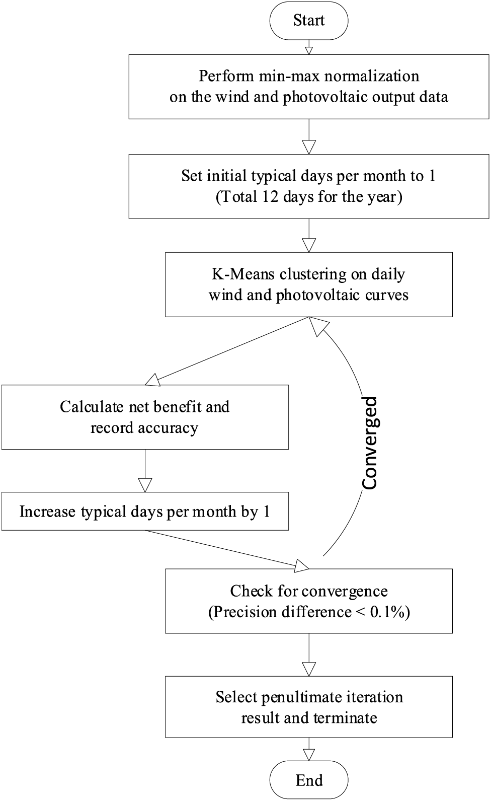
Figure 1: Solving flowchart
Subsequently, these steps are employed to identify the optimal number of typical days for each month:
1. Apply min-max normalization to the wind and photovoltaic output data from the original scenarios;
2. Initialize the typical days per month to 1, resulting in a total of 12 typical days for the year;
3. Employ the K-Means clustering method to group the time series wind and photovoltaic characteristic curves of each natural day into typical day data for each month;
4. Calculate the net benefit C of a certain typical planning scenario under the typical day’s output scenario and the precise net benefit value
5. Increment the number of typical days per month by 1;
6. Check for convergence; if not converged, use the new value of typical days and return to step 3 for the next iteration (the convergence criterion in this paper is set to a precision difference of less than 0.1% between two consecutive calculations);
7. Select the calculation result from the second-to-last iteration and conclude the iteration.
At this stage, the energy storage grid alternative benefit measurement model, based on wind and photovoltaic typical day output scenarios, is a standard mixed-integer linear programming model that can be addressed using commercial solvers like Gurobi. Therefore, we utilize the mixed-integer linear programming (MILP) approach to solve the model. The solution is obtained in an environment equipped with MATLAB R2018a and Gurobi 10.0.0, utilizing a 2.40 GHz CPU and 8 GB of RAM.
We utilized the modified IEEE RTS-24 node test system to quantitatively evaluate the multidimensional value of the GAES system. Compressed air was selected. The parameters of storage operation and transmission line data were shown in Table 1. And the generator data and node load were sourced from Reference [29]. The schematic diagram is illustrated in Fig. 2. The modified IEEE RTS-24 node system includes three interconnection lines—7–27, 13–39, and 22–41—highlighted in red, with their parameters detailed in Table 1. The maximum ramp-up and down power per unit time for an interconnection line is 40% of the line’s rated capacity [5]. The left side of the system is designated as Region I, and the right side as Region II. Region I is used to simulate a high wind power penetration system, with wind power nodes at 11, 19, and 23, having grid-connected capacities of 2000, 2000, and 3000 MW, respectively. Region II simulates a low wind power penetration system, with wind power nodes at 43 and 47, each with a capacity of 1000 MW. The wind curtailment penalty cost is set at 1000 yuan/MWh, and the time-of-use electricity price is referenced from [30]. The number of new transmission lines serves as a variable, with their capacity equivalent to the cumulative capacity of the existing single-line transmission lines within the same corridor. The remaining parameters are listed in Table 2.
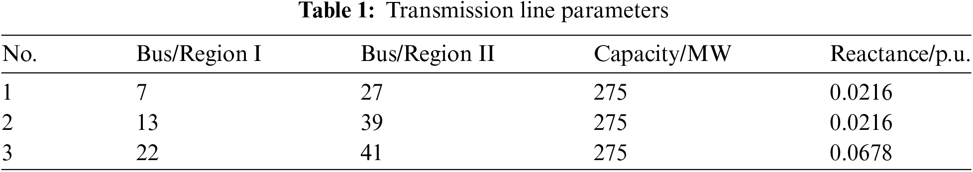
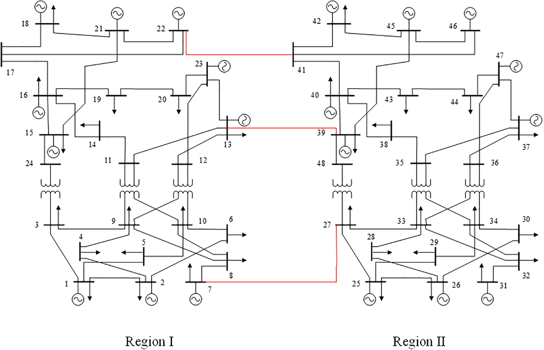
Figure 2: Topology of the modified IEEE RTS-24 system

The value assessment model for GAES proposed in this paper employs an operational mode that considers the limits of interconnection line power, with the minimum interconnection line load rate set to 0.4 and the maximum to 0.8. To validate the superiority, two cases are conducted in this section. Case 1 involves multi-regional transmission grid planning considering the operational mode of interconnection lines, laying the groundwork for subsequent cost-benefit analysis of GAES. Case 2 analyses the cost-benefit of GAES aimed at storage-transmission collaborative planning.
In Table 3, it is clear that the highest proportion of costs is attributed to generation costs, with significant shares also coming from the start-up and shut-down costs of generator units. This occurs due to the large-scale integration of wind power, which increases the volatility of the system’s net load, thereby enhancing the system’s demand for flexibility. Conventional generator units enhance power system flexibility through start-up and shut-down operations, thereby increasing associated operating costs. From the transmission expansion plans, it can be noted that the new lines are concentrated around nodes 11, 19, 23, 43, and 47, which are wind farm grid connection nodes. There are also new lines added to address the inadequate transmission capacity of existing lines, such as lines 6–10, 7–8, and 10–12.

Analysing the cost data in Table 4 and comparing it in Table 3, it is clear that generation costs remain the largest expenditure item. The investment cost of energy storage also occupies a significant proportion. However, the incorporation of energy storage significantly reduces wind curtailment losses and brings multiple benefits.
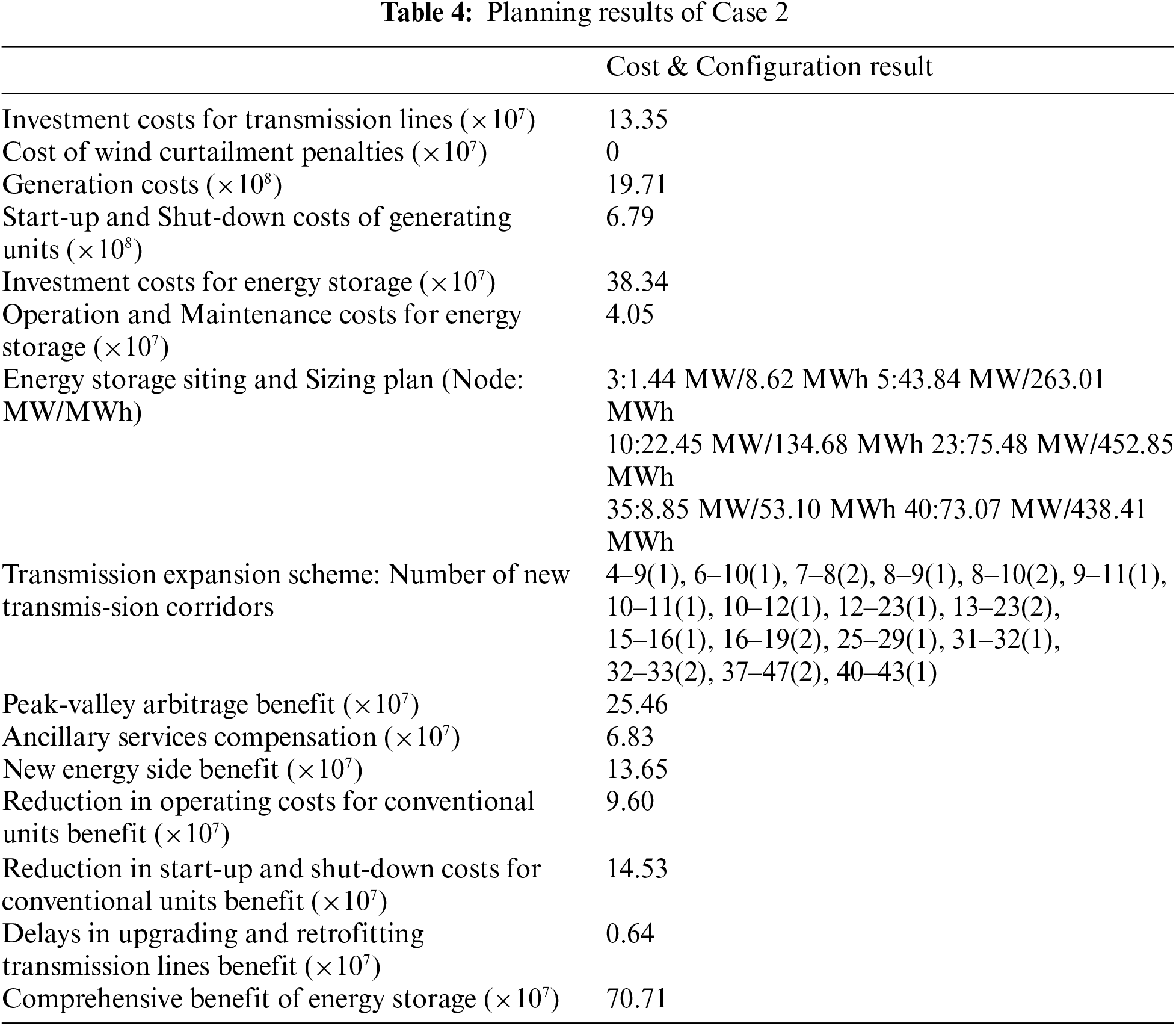
From the energy storage siting and sizing plan, it is apparent that energy storage stations are widely distributed. The largest energy storage station is established at node 23, which has the highest wind power integration capacity. The net load fluctuation at this node is substantial, and establishing an energy storage station here can enhance wind power absorption at this node.
From the benefit data in Table 4, we see that the overall benefits for various stakeholders involved with energy storage are all positive. This indicates that energy storage, as an independent operator, can participate in system operations. By shifting electricity and power, it not only achieves economic gains for itself but also creates significant social benefits. Under market mechanisms, energy storage stations can profit from peak-valley arbitrage and auxiliary service compensation, realizing a win-win situation.
5.3 The Impact of Regional Connectivity
To verify the advantages of multi-regional interconnected planning, this section introduces two new cases: Case 1 involves two sub-regions operating independently, with no power flow exchange between them. Case 2 considers the joint planning of the transmission grid and energy storage across the two regions, excluding the benefits of storage. In this case, the interconnection line operates by taking into account the limits of the transmission power, with a minimum load rate of 0.4 and a maximum rate of 0.8. The plan derived from the power grid alternative energy storage benefit measurement model is referred to as Case 3.
The comparative analysis of Case 1 and Case 2 from Table 5 reveals that, under regional interconnection, the total cost of synchronized planning between the power grid and energy storage amounts to 3.066 billion, which signifies a reduction of 1.62 billion, or approximately 34.57%, compared to the total cost of independent planning for each region. A detailed comparison of the cost composition between the two case studies indicates that all categories of costs in Case 2 are lower than those in 1. The predominant factor contributing to the decrease in total cost is the reduction in generation costs, followed through the costs associated with investing in and operating energy storage, along with the capital costs of transmission lines, with the cost related to wind curtailment penalties diminishing by approximately 30.43%.
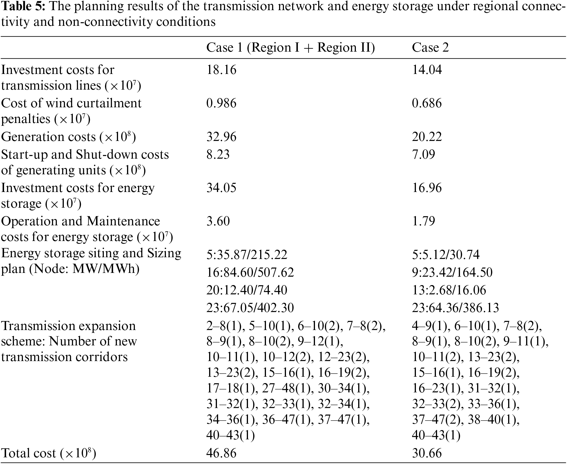
Under multi-regional coordinated planning, the implementation of storage significantly reduces the curtailment penalty costs. A comparison between Table 5 and Table 3 reveals that under multi-regional coordinated planning, the implementation of energy storage can markedly decrease the system’s wind curtailment penalty costs. Specifically, in Case 2, the wind curtailment penalty cost is 6.86 million yuan, which is 129.6 million yuan less than the penalty cost in the single transmission network planning scenario. This indicates that multi-regional coordinated planning can more effectively utilize wind resources, reduce curtailment, and thereby lower the overall system costs. By reducing curtailment, the grid can better integrate renewable energy, increase the utilization rate of renewable resources, reduce dependence on fossil fuels, and consequently lower carbon emissions.
Integrating energy storage enhances the system’s flexibility, reducing the need for start-up and shut-down operations of generation units. In the multi-regional coordinated planning scenario, the start-up and shut-down costs of generation units are reduced by 115 million yuan, approximately 13.9% less than in the single transmission network planning scenario. This demonstrates that energy storage systems can effectively smooth out power supply and demand fluctuations, reducing operational interruptions and maintenance costs. Higher system flexibility means that the grid can better respond to load fluctuations and unexpected events, enhancing the stability of power supply.
From the comparison of energy storage investment costs in Fig. 3, it can be seen that Case 3 has the highest energy storage investment cost, followed by Case 1, and finally Case 2. The comparison between Case 2 and Case 3 indicates that when the energy storage system functions as an independent operator within the power system, considering the comprehensive benefits of GAES in coordinated transmission network planning can effectively promote its integration into the power grid. The comparison between Case 1 and Case 2 shows that multi-regional coordinated planning enhances system flexibility and regulation capability, thereby reducing the demand for energy storage. As a result, the energy storage investment cost in Case 2 is reduced by 170.9 million yuan compared to Case 1, a cost reduction of nearly 50%. This indicates that multi-regional coordinated planning can not only optimize the allocation of energy storage but also significantly reduce.
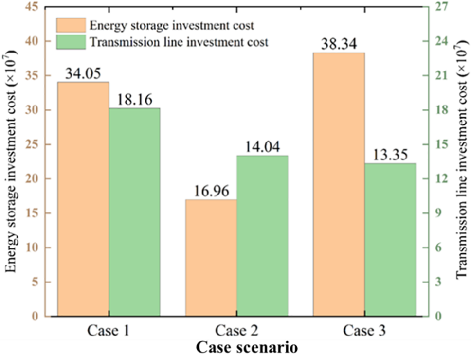
Figure 3: Comparison of investment cost
From the comparison of transmission network investment costs in Fig. 3, it can be seen that from Case 1 to Case 3, the investment costs for transmission lines sequentially decrease. Case 2 sees a reduction in transmission line investment costs by 41.2 million yuan compared to Case 1. This decrease is attributed to the increased system flexibility brought about by regional interconnection, which enhances the system’s ability to handle peak loads, provides more pathways for power delivery, and subsequently reduces the system’s demand for transmission line capacity. This delay in the need for new transmission line investments is thus achieved.
The further reduction in transmission line investment costs from Case 2 to Case 3 is due to the larger energy storage capacity configured in Case 3. With greater storage capacity, the system’s regulation capabilities are stronger, reducing the need for expanding transmission line capacity even further.
The comparison of generation costs in Fig. 4 reveals that regional interconnection allows generators in different regions to coordinate their operations. This coordination enables the full utilization of lower-cost generators while reducing the output of higher-cost generators. As a result, the overall generation costs in Case 2 are significantly lower compared to Case 1. This cost reduction is achieved by optimizing the dispatch of generation units, ensuring that the most cost-effective units are utilized to meet the demand. The ability to leverage lower-cost generation resources across regions highlights the economic benefits of regional interconnection, which can lead to more efficient and cost-effective power generation.
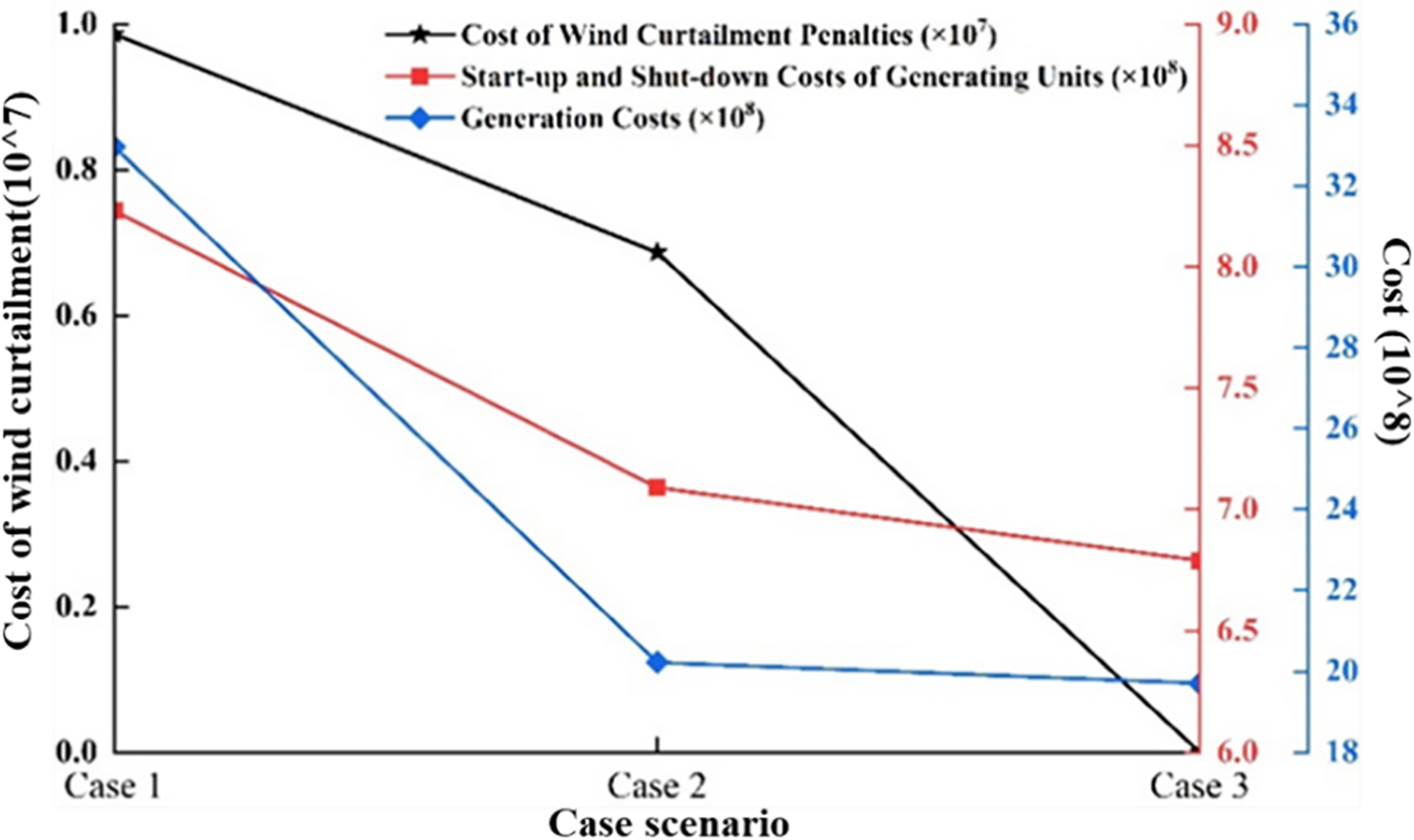
Figure 4: Comparison of system operating costs
Regional interconnection also enhances the overall flexibility of the power system, improving its regulation capabilities. When addressing significant fluctuations in wind power and load demand, certain generation units no longer require frequent start-ups or shut-downs. This reduction in the frequency of these operations results in substantial cost savings. In Case 2, start-up and shut-down expenses decrease by 115 million yuan compared to Case 1, highlighting the effectiveness of regional interconnection in boosting system flexibility. This increased adaptability enables the system to better accommodate variations in renewable energy output and load demand, alleviating operational stress on generation units and reducing maintenance costs.
In the context of grid interconnection, Case 3 features a larger energy storage capacity configuration than Case 2. This added capacity enhances the system’s flexibility, leading to lower generation costs as well as reduced start-up and shut-down expenses in Case 3 compared to Case 2. The increased energy storage capacity allows the system to capture excess energy during low demand periods and release it during high demand periods, effectively balancing supply and demand. This capability decreases reliance on expensive peaking power plants and minimizes dependence on fossil fuel-based generation, contributing to a more sustainable and cost-effective power system.
The analysis of wind curtailment penalty costs in Fig. 4 indicates that both regional interconnection and increased energy storage capacity enhance system flexibility. Consequently, wind curtailment penalty costs decrease progressively from Case 1 to Case 3. In Case 3, the planning model for storage and transmission incorporates the comprehensive benefits of integrating energy storage within the grid, resulting in a higher final energy storage capacity configuration. This leads to zero wind curtailment penalty costs in Case 3 compared to Case 2. The removal of wind curtailment penalties highlights the effectiveness of coordinated planning in maximizing the use of renewable energy resources and reducing economic losses related to curtailment.
In summary, multi-regional coordinated planning can significantly enhance system flexibility, providing adequate regulation capabilities during substantial fluctuations in wind power. This strategy optimizes the sizing, thereby lowering the overall operational costs of the system. By accounting for the advantages of integrating storage into the grid within the joint planning model, the implementation of energy storage can be effectively encouraged. This improvement boosts the system’s ability to use new energy, diminishes dependence on fossil fuels, and supports a more eco-friendly and resilient power system.
5.4 The Impact of Interconnection Line Operational Modes
To assess the impact of different operational modes on the results of the coordinated planning scheme for the transmission network and alternative energy storage, three cases were developed: Case 1, where the interconnection line load rate ranges between 0.4 and 0.8, considering both upper and lower transmission power limits; Case 2, where the interconnection line load rate ranges from 0 to 1, considering only the upper transmission power limit; and Case 3, where the interconnection line load rate is fixed at 0.6, representing a constant power transmission mode. The specific costs, benefits, and configuration results for these cases are presented in Table 6.
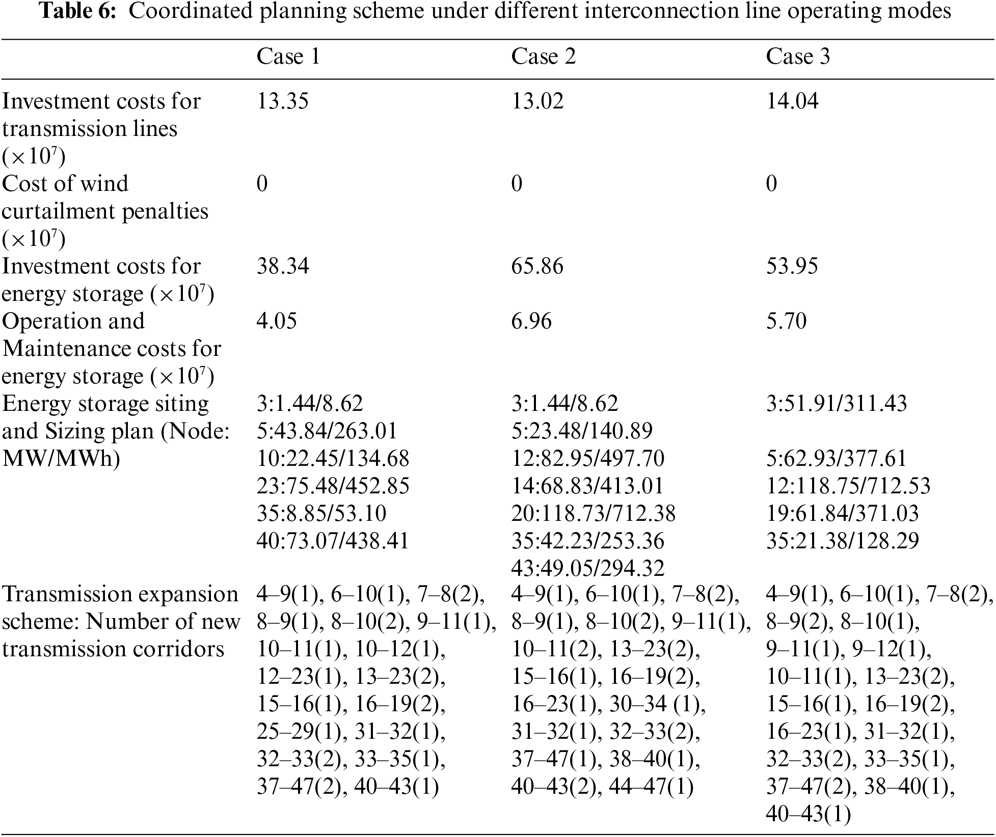
As seen in Table 6, the wind curtailment penalty costs for all three cases are zero. Case 2, with the largest energy storage planning capacity, incurs the lowest line investment cost. Conversely, Case 1 has the lowest energy storage investment cost, amounting to 383.4 million yuan. Fig. 5 illustrates the load rate variations of the three interconnection lines over the entire dispatch period for each case. Table 7 provides the average load rates of the three interconnection lines for each case.
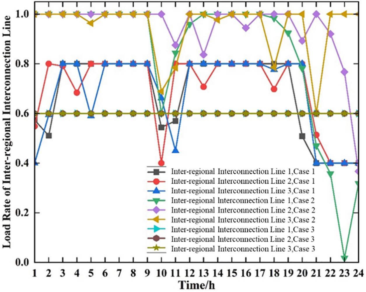
Figure 5: Load rate of each interconnection line across different cases
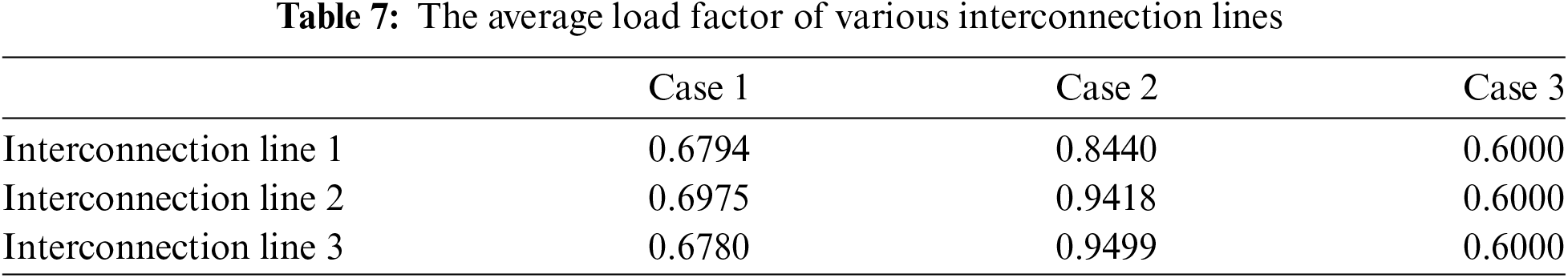
From the data in Table 7, it is observed that Case 2’s energy storage investment cost is significantly higher than that of Case 1, indicating a notably larger storage planning capacity. Consequently, the system flexibility in Case 2 is higher, enhancing the system’s ability to regulate peak loads. This results in a reduction of 2.47% in transmission line investment costs for Case 2 compared to Case 1. Fig. 5 indicates that the load rate variations in Case 1 are more stable, while Case 2 exhibits greater fluctuations and higher load rate levels.
According to the data in Table 6, when comparing Case 1 with Case 3, Case 3 has higher energy storage investment costs, indicating a larger storage planning capacity. However, the transmission line costs in Case 3 are still higher than those in Case 1. This suggests that a constant power transmission mode for interconnection lines reduces system flexibility, increases the demand for energy storage, and leads to excessive investment in energy storage. The constant power transmission mode limits the system’s ability to adjust under different load conditions, requiring more energy storage to balance supply and demand, thus increasing energy storage investment costs.
From Table 7, it is evident that the average load rates of all interconnection lines in Case 2 exceed 0.8 and are higher than those in Case 1. Higher load rates for interconnection lines result in reduced reserve capacity. Thus, a comparative analysis of the planning results between Case 1 and Case 2 indicates that considering only the upper transmission power limit for interconnection lines leads to excessive investment in energy storage and results in higher load rates for the interconnection lines, thereby reducing reserve capacity and affecting mutual reserves between subregions. This suggests that when planning interconnection lines, it is insufficient to consider only the upper transmission power limit; the system’s reserve capacity and flexibility requirements must also be taken into account.
From these results, it can be concluded that different operational modes for interconnection lines affect their utilization rates and the fluctuation of power flows. The operational mode considering both upper and lower transmission power limits for interconnection lines is more effective in fully utilizing energy storage resources, thereby enhancing system economic efficiency compared to the other two operational modes. In contrast, considering only the upper transmission power limit or a constant power transmission mode leads to excessive investment in energy storage, reduced system flexibility, and decreased economic efficiency. Therefore, when planning interconnection lines, both upper and lower transmission power limits should be considered to fully utilize energy storage resources and improve the overall economic efficiency of the system.
The comparative analysis shows that the operational mode considering both upper and lower transmission power limits has significant advantages in improving system flexibility and economic efficiency. This mode not only reduces energy storage investment costs but also increases the utilization rate of interconnection lines, reduces the need for reserve capacity, and enhances mutual reserves between subregions. Additionally, this mode can better handle power flow fluctuations, improving system stability and reliability.
In summary, different operational modes for interconnection lines have a significant impact on the economic efficiency and flexibility of the system. The operational mode considering both upper and lower transmission power limits can more effectively utilize energy storage resources, reduce energy storage investment costs, and improve the economic efficiency and flexibility of the system. This provides important reference points for optimizing grid planning and energy storage systems, contributing to a more efficient and sustainable power system.
5.5 The Impact of Wind Power Grid Integration Capacity
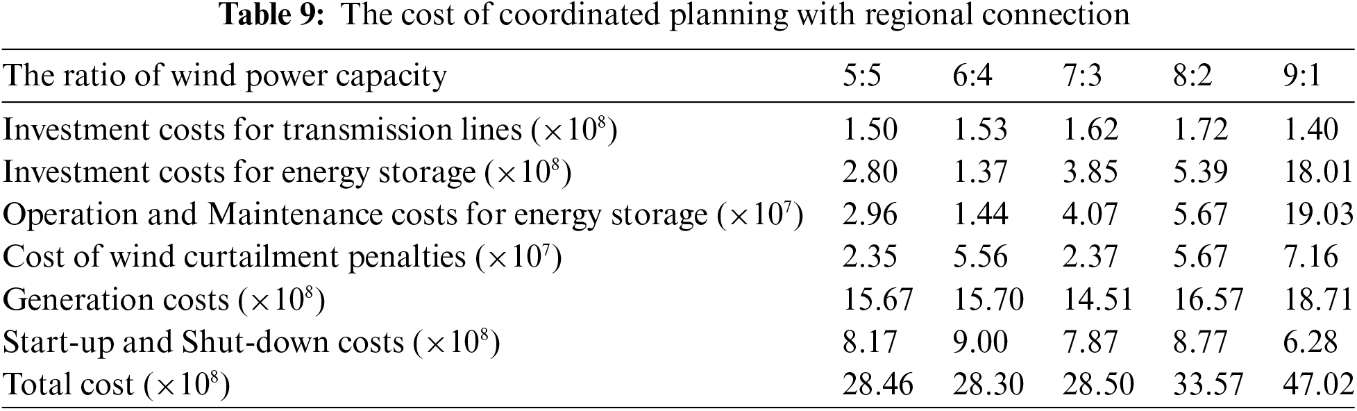
Based on the findings from Section 4.2, multi-regional collaborative planning can enhance the system’s regulatory capabilities and increase the economic efficiency of the planning schemes. To further explore the impact of varying wind power grid integration capacities across regions on the economic efficiency of the planning schemes, this section maintains a fixed total wind power grid integration capacity of 10,000 MW for the two regions. This capacity is distributed in various proportions between the two regional grids, with five wind power capacity ratios set at 5:5, 6:4, 7:3, 8:2, and 9:1. These ratios are applied to both the individual planning models for the transmission network and energy storage for each region, in addition to the collaborative planning model for the two regions. The system parameters and wind power grid integration points remain consistent with those described in Section 4.1. The detailed costs for each planning scheme under different wind power integration capacity ratios are presented in Tables 8 and 9.
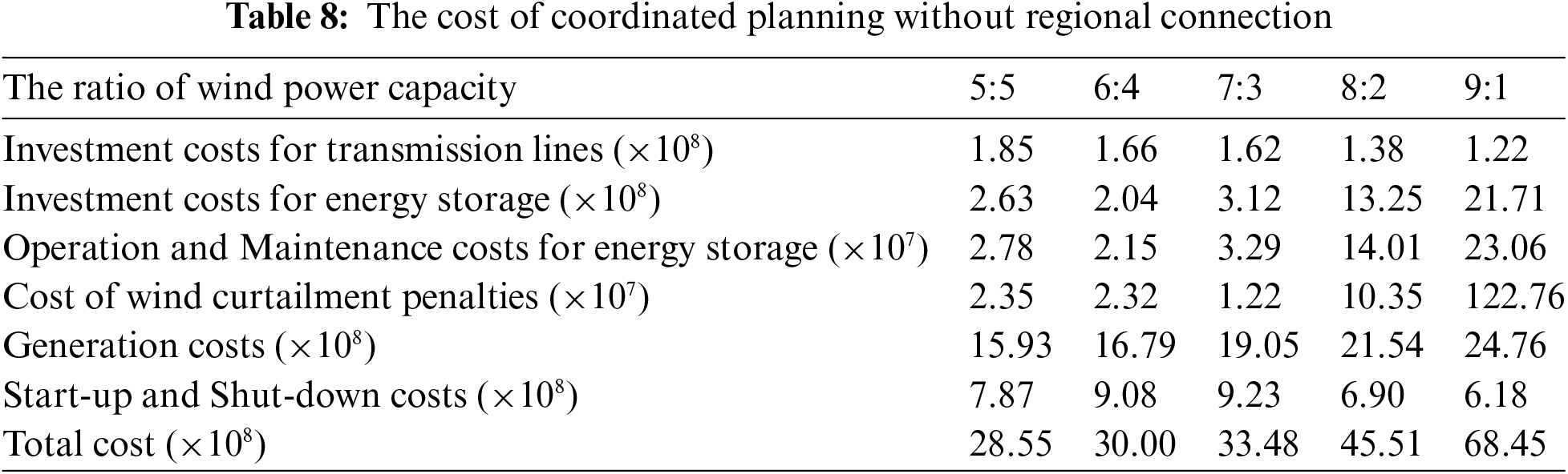
From Table 8, as the difference in wind power grid integration capacity increases, the total investment in transmission lines for the independently planned regions gradually decreases, while the total investment in energy storage gradually increases. This phenomenon occurs because the lower wind power region requires less capacity expansion in transmission lines. Conversely, the higher wind power region reaches its limit in absorbing wind power through line expansion since its load level is relatively low, making it challenging to absorb a large volume of wind power. Additionally, the number of line expansions in specific transmission corridors has reached its maximum, resulting in increased congestion and wind curtailment, thereby reducing the system’s economic efficiency. Consequently, more energy storage is needed to absorb the peak wind power, leading to a rise in total energy storage investment costs.
A comparison of Tables 8 and 9 reveals that after the interconnection of the two regions, the investment costs for energy storage, as well as the system’s generation costs and wind curtailment penalty costs, decrease significantly. This decreasing trend becomes more evident as the difference in wind power grid integration capacity grows. Regional interconnection enhances system flexibility and regulatory capabilities, allowing for the absorption of more wind power, which in turn lowers generation costs. Furthermore, the improved regulatory capability reduces the system’s reliance on energy storage, resulting in a gradual decline in total energy storage investment costs.
The comparison of the total costs between the independently planned and collaboratively planned transmission and storage regions is illustrated in Fig. 6.
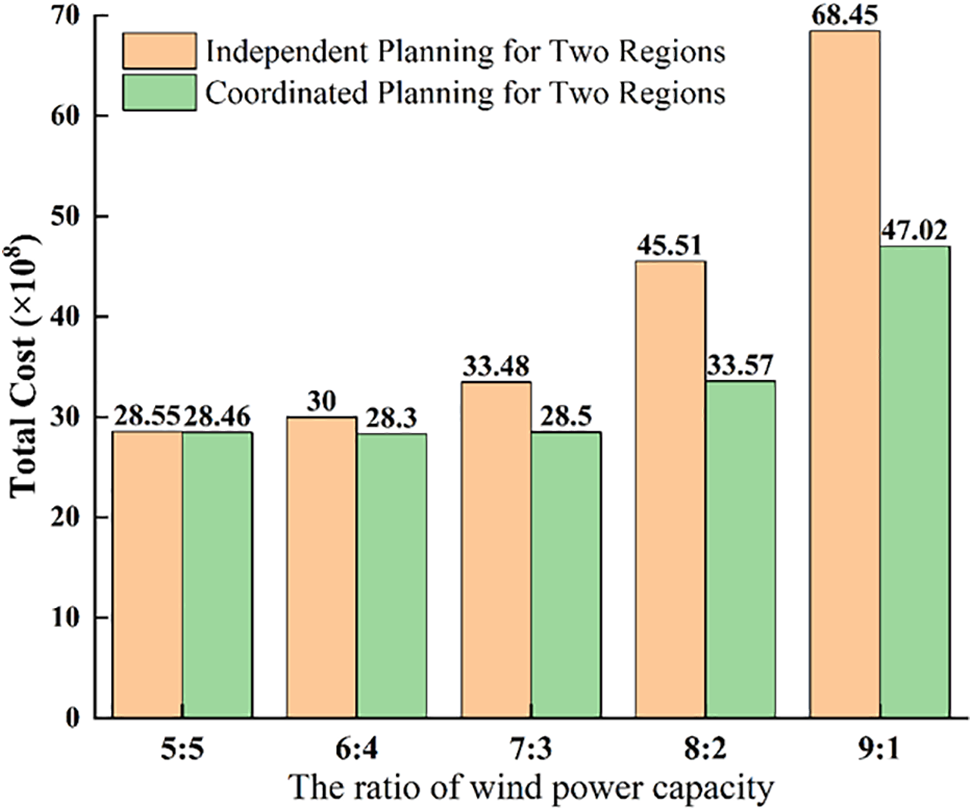
Figure 6: Comparison of total cost
From Fig. 6, the greater the disparity in wind power grid integration capacity, the more pronounced the reduction in total costs for the collaborative planning of the two regions compared to their individual planning. When the wind power grid integration capacity ratio between the two regions is 5:5, meaning the wind power integration capacities are equal, the total cost for the collaborative planning is 2.846 billion, which is only 0.09 billion lower (approximately 0.3%) than the total cost of 2.855 billion for the individual planning. However, when the wind power grid integration capacity ratio is 9:1, the total cost reduction amounts to 2.143 billion, or about 31.3%.
In summary, the greater the disparity in wind power grid integration capacity between regions, the more significant the economic improvement achieved by multi-regional collaborative planning compared to individual regional planning.
Taking into account the uneven distribution of renewable energy across various provinces and the advancement of energy storage marketization, this paper seeks to maximize the net pure revenue of GAES by developing a value assessment model. This model incorporates the operational limitations of inter-regional grid interconnection lines, power and energy balance requirements, generator unit limitations, and energy storage operation restrictions. Through the analysis of practical cases, the effectiveness of model is demonstrated, leading to the following conclusions:
1) The GAES value assessment framework presented comprehensively takes into account the advantages associated with energy storage, including investment costs, peak-valley compensation, peak shaving ancillary service compensation, conventional unit benefits, additional grid-connected new energy benefits, and grid-side benefits. This framework effectively calculates the actual benefits of GAES at various stages, demonstrating strong practical value and good scalability. The results show that various benefits related to energy storage are on the rise, and energy storage, as an independent operating entity, interacts with system operations. Through energy conversion, it not only improves its own economic benefits but also has a significant impact on social welfare transfer. Under the market mechanism, GAES mainly profits from peak-valley arbitrage and ancillary service compensation, achieving a win-win situation.
2) Integrating GAES into the joint planning model for the grid and storage can significantly enhance the grid’s adaptability. Additionally, multi-regional interconnected operations better leverage the benefits of GAES. In comparison to traditional storage and grid planning models, the coordinated planning that considers multi-regional interconnected operations increases energy storage investment costs by approximately 125%. However, at the system level, it effectively lowers the total system cost by around 34.57%. This approach also enhances the system’s capacity to incorporate new energy, reducing wind curtailment penalty costs by 30.43% and improving the economic benefits for both the grid and the generating units. Furthermore, coordinated energy storage planning across multiple regions can greatly increase system flexibility, leading to a decrease in the frequency of generator start-up and shut-down operations, with start-stop costs reduced by about 14% compared to planning for a single transmission grid. Moreover, accounting for the value of grid-replacing energy storage in the joint planning can offer additional power transmission pathways, thus decreasing the system’s reliance on transmission line capacity and resulting in a reduction of transmission line investment costs by up to 27%.
3) Multi-regional coordinated planning significantly improves system flexibility, providing sufficient regulatory capacity to manage large fluctuations in wind power output. The operation mode of multi-regional interconnected lines also significantly affects the value assessment of GAES and system economic benefits. Among various operation and maintenance modes, considering the upper and lower limits of interconnected line transmission power is the optimal way to effectively utilize energy storage resources. It can effectively reduce load fluctuation rates and decrease the system’s reserve capacity requirements. Furthermore, the greater the difference in wind power grid-connected capacity between interconnected regions, the more significant the reduction in system costs. When the wind power grid-connected capacity ratio between two interconnected regions is 9:1, the total system cost can be reduced by about 31% compared to regional independent planning, indicating that multi-regional coordinated planning has a significant effect on improving system economic benefits.
Acknowledgement: The Technology Project of State Grid Jibei Electric Power Supply Co., Ltd., contributed to this study.
Funding Statement: This research was funded by the Technology Project of State Grid Jibei Electric Power Supply Co., Ltd. (Grant Number: 52018F240001).
Author Contributions: Bingqing Wu, Conceptualization, Methodology, Software, Validation, Project administration, Writing—review & editing; Yunli Yue, Formal analysis, Methodology, Investigation, Formal analysis, Writing—review & editing; Yi Zhou, Resources, Programming, Visualization, Data curation; Hengyu Zhou, Writing—review & editing, Data analysis, Project administration; Haowen Guan, Methodology, Software, Formal analysis, Writing—review & editing; Zhenjiang Shi, Investigation, Formal analysis, Software, Validation; Zili Chen, Conceptualization, Programming, Supervision, Funding acquisition; Zhaoyuan Wu, Methodology, Software, Supervision, Funding acquisition. All authors reviewed the results and approved the final version of the manuscript.
Availability of Data and Materials: Data available on request from the authors.
Ethics Approval: Not applicable.
Conflicts of Interest: Authors Bingqing Wu, Yunli Yue, Yi Zhou, Haowen Guan, Zhenjiang Shi were employed by the State Grid Jibei Electric Power Economic Research Institute. The remaining authors declare that the research was conducted in the absence of any commercial or financial relationships that could be construed as a potential conflict of interest.
References
1. X. Chang et al., “The coupling effect of carbon emission trading and tradable green certificates under electricity marketization in China,” Renew. Sustain. Energ. Rev., vol. 187, 2023, Art. no. 113750. doi: 10.1016/j.rser.2023.113750. [Google Scholar] [CrossRef]
2. Z. Wu et al., “Sharing economy in local energy markets,” J. Mod. Power Syst. Clean Energy, vol. 11, pp. 714–726, 2023. doi: 10.35833/MPCE.2022.000521. [Google Scholar] [CrossRef]
3. Y. Wang and J. Cai, “Renewable energy development in North West China,” Curr. Sustain./Renew. Energy Rep., vol. 4, pp. 56–62, 2017. doi: 10.1007/s40518-017-0069-1. [Google Scholar] [CrossRef]
4. S. A. Mansouri, A. Rezaee Jordehi, M. Marzband, M. Tostado-Véliz, F. Jurado and J. A. Aguado, “An IoT-enabled hierarchical decentralized framework for multi-energy microgrids market management in the presence of smart prosumers using a deep learning-based forecaster,” Appl. Energy, vol. 333, 2023, Art. no. 120560. doi: 10.1016/j.apenergy.2022.120560. [Google Scholar] [CrossRef]
5. H. Zhang, H. Cheng, L. Liu, S. Zhang, Q. Zhou and L. Jiang, “Coordination of generation, transmission and reactive power sources expansion planning with high penetration of wind power,” Int. J. Electr. Power Energy Syst., vol. 108, pp. 191–203, 2019. doi: 10.1016/j.ijepes.2019.01.006. [Google Scholar] [CrossRef]
6. M. Ma, H. Huang, X. Song, F. Peña-Mora, Z. Zhang and J. Chen, “Optimal sizing and operations of shared energy storage systems in distribution networks: a bi-level programming approach,” Appl. Energy, vol. 307, 2022, Art. no. 118170. doi: 10.1016/j.apenergy.2021.118170. [Google Scholar] [CrossRef]
7. J. Wang, F. Ma, E. Bouri, and J. Zhong, “Volatility of clean energy and natural gas, uncertainty indices, and global economic conditions,” Energy Econ., vol. 108, 2022, Art. no. 105904. doi: 10.1016/j.eneco.2022.105904. [Google Scholar] [CrossRef]
8. F. Baumgarte, G. Glenk, and A. Rieger, “Business models and profitability of energy storage,” iScience, vol. 23, 2020, Art. no. 101554. doi: 10.1016/j.isci.2020.101554. [Google Scholar] [PubMed] [CrossRef]
9. Z. Jia, B. Lin, and S. Wen, “Electricity market reform: The perspective of price regulation and carbon neutrality,” Appl. Energy, vol. 328, 2022, Art. no. 120164. doi: 10.1016/j.apenergy.2022.120164. [Google Scholar] [CrossRef]
10. H. Guo et al., “Power market reform in China: Motivations, progress, and recommendations,” Energy Policy, vol. 145, 2020, Art. no. 111717. doi: 10.1016/j.enpol.2020.111717. [Google Scholar] [CrossRef]
11. H. Jafarizadeh, E. Yamini, S. M. Zolfaghari, F. Esmaeilion, M. E. H. Assad and M. Soltani, “Navigating challenges in large-scale renewable energy storage: Barriers, solutions, and innovations,” Energy Rep., vol. 12, pp. 2179–2192, 2024. doi: 10.1016/j.egyr.2024.08.019. [Google Scholar] [CrossRef]
12. Z. Wu, J. Wang, M. Zhou, Q. Xia, C. W. Tan and G. Li, “Incentivizing frequency provision of power-to-hydrogen toward grid resiliency enhancement,” IEEE Trans. Ind. Inform., vol. 19, pp. 9370–9381, 2023. doi: 10.1109/TII.2022.3228379. [Google Scholar] [CrossRef]
13. M. Kazemi and M. R. Ansari, “An integrated transmission expansion planning and battery storage systems placement—A security and reliability perspective,” Int. J. Electr. Power Energy Syst., vol. 134, 2022, Art. no. 107329. doi: 10.1016/j.ijepes.2021.107329. [Google Scholar] [CrossRef]
14. H. Mazaheri, M. Moeini-Aghtaie, M. Fotuhi-Firuzabad, P. Dehghanian, and M. Khoshjahan, “A linearized transmission expansion planning model under N − 1 criterion for enhancing grid-scale system flexibility via compressed air energy storage integration,” IET Gen., Trans. Distrib., vol. 16, pp. 208–218, 2022. doi: 10.1049/gtd2.12226. [Google Scholar] [CrossRef]
15. A. Rezaee Jordehi, S. A. Mansouri, M. Tostado-Véliz, A. Iqbal, M. Marzband and F. Jurado, “Industrial energy hubs with electric, thermal and hydrogen demands for resilience enhancement of mobile storage-integrated power systems,” Int. J. Hydrogen Energy, vol. 50, pp. 77–91, 2024. doi: 10.1016/j.ijhydene.2023.07.205. [Google Scholar] [CrossRef]
16. W. Gan et al., “Security constrained co-planning of transmission expansion and energy storage,” Appl. Energy, vol. 239, pp. 383–394, 2019. doi: 10.1016/j.apenergy.2019.01.192. [Google Scholar] [CrossRef]
17. M. Barbar, D. S. Mallapragada, and R. Stoner, “Decision making under uncertainty for deploying battery storage as a non-wire alternative in distribution networks,” Energy Strategy Rev., vol. 41, 2022, Art. no. 100862. doi: 10.1016/j.esr.2022.100862. [Google Scholar] [CrossRef]
18. H. A. Gil and G. Joos, “On the quantification of the network capacity deferral value of distributed generation,” IEEE Trans. Power Syst., vol. 21, pp. 1592–1599, 2006. doi: 10.1109/TPWRS.2006.881158. [Google Scholar] [CrossRef]
19. Y. Pan, L. Ju, S. Yang, X. Guo, and Z. Tan, “A multi-objective robust optimal dispatch and cost allocation model for microgrids-shared hybrid energy storage system considering flexible ramping capacity,” Appl. Energy, vol. 369, 2024, Art. no. 123565. doi: 10.1016/j.apenergy.2024.123565. [Google Scholar] [CrossRef]
20. A. Selim, H. Mo, H. Pota, and D. Dong, “Optimal scheduling of battery energy storage systems using a reinforcement learning-based approach,” IFAC-PapersOnLine, vol. 56, pp. 11741–11747, 2023. doi: 10.1016/j.ifacol.2023.10.546. [Google Scholar] [CrossRef]
21. S. Wang, G. Geng, and Q. Jiang, “Robust co-planning of energy storage and transmission line with mixed integer recourse,” IEEE Trans. Power Syst., vol. 34, pp. 4728–4738, 2019. doi: 10.1109/TPWRS.2019.2914276. [Google Scholar] [CrossRef]
22. X. Y. Wang, D. M. Vilathgamuwa, and S. S. Choi, “Determination of battery storage capacity in energy buffer for wind farm,” IEEE Trans. Energy Convers., vol. 23, pp. 868–878, 2008. doi: 10.1109/TEC.2008.921556. [Google Scholar] [CrossRef]
23. F. Verástegui, A. Lorca, D. E. Olivares, M. Negrete-Pincetic, and P. Gazmuri, “An adaptive robust optimization model for power systems planning with operational uncertainty,” IEEE Trans. Power Syst., vol. 34, pp. 4606–4616, 2019. doi: 10.1109/TPWRS.2019.2917854. [Google Scholar] [CrossRef]
24. U. Akram, M. Khalid, and S. Shafiq, “Optimal sizing of a wind/solar/battery hybrid grid-connected microgrid system,” IET Renew. Power Gener., vol. 12, pp. 72–80, 2018. doi: 10.1049/iet-rpg.2017.0010. [Google Scholar] [CrossRef]
25. S. Pineda and J. M. Morales, “Chronological time-period clustering for optimal capacity expansion planning with storage,” IEEE Trans. Power Syst., vol. 33, pp. 7162–7170, 2018. doi: 10.1109/TPWRS.2018.2842093. [Google Scholar] [CrossRef]
26. Z. Wu et al., “An incentive profit-sharing mechanism for welfare transfer in balancing market integration,” Renew. Sustain. Energ. Rev., vol. 168, 2022, Art. no. 112762. doi: 10.1016/j.rser.2022.112762. [Google Scholar] [CrossRef]
27. S. Gonzato, K. Bruninx, and E. Delarue, “Long term storage in generation expansion planning models with a reduced temporal scope,” Appl. Energy, vol. 298, 2021, Art. no. 117168. doi: 10.1016/j.apenergy.2021.117168. [Google Scholar] [CrossRef]
28. L. Kotzur, P. Markewitz, M. Robinius, and D. Stolten, “Impact of different time series aggregation methods on optimal energy system design,” Renew. Energy, vol. 117, pp. 474–487, 2018. doi: 10.1016/j.renene.2017.10.017. [Google Scholar] [CrossRef]
29. Y. Huang, B. Liu, K. Wang, and X. Ai, “Joint planning of energy storage and transmission considering wind-storage combined system and demand side response,” IOP Conf. Series: Earth Environ. Sci., vol. 104, 2017, Art. no. 012004. doi: 10.1088/1755-1315/104/1/012004. [Google Scholar] [CrossRef]
30. X. Yang, Q. Guo, J. Gui, R. Chai, and X. Liu, “A storage and transmission joint planning method for centralized wind power transmission,” Comput. Mater. Contin., vol. 68, pp. 1081–1097, 2021. doi: 10.32604/cmc.2021.016375. [Google Scholar] [CrossRef]
Cite This Article
 Copyright © 2025 The Author(s). Published by Tech Science Press.
This work is licensed under a Creative Commons Attribution 4.0 International License , which permits unrestricted use, distribution, and reproduction in any medium, provided the original work is properly cited.
 Downloads
 Citation Tools