
 Submit a Paper
 Propose a Special lssue
 Open Access
ARTICLE

Improve Strategy for Transient Power Angle Stability Control of VSG Combining Frequency Difference Feedback and Virtual Impedance
1 Substation Management Office, Qujing Bureau of CSG EHV Power Transmission Company, Qujing, 655000, China
2 College of Electrical Engineering, Sichuan University, Chengdu, 610065, China
* Corresponding Author: Yihan Chen. Email:
Energy Engineering 2025, 122(2), 651-666. https://doi.org/10.32604/ee.2025.057670
Received 24 August 2024; Accepted 24 December 2024; Issue published 31 January 2025
 View Full Text
 Download PDF
Abstract
As the penetration rate of distributed energy increases, the transient power angle stability problem of the virtual synchronous generator (VSG) has gradually become prominent. In view of the situation that the grid impedance ratio (R/X) is high and affects the transient power angle stability of VSG, this paper proposes a VSG transient power angle stability control strategy based on the combination of frequency difference feedback and virtual impedance. To improve the transient power angle stability of the VSG, a virtual impedance is adopted in the voltage loop to adjust the impedance ratio R/X; and the PI control feedback of the VSG frequency difference is introduced in the reactive power-voltage link of the VSG to enhance the damping effect. The second-order VSG dynamic nonlinear model considering the reactive power-voltage loop is established and the influence of different proportional integral (PI) control parameters on the system balance stability is analyzed. Moreover, the impact of the impedance ratio R/X on the transient power angle stability is presented using the equal area criterion. In the simulations, during the voltage dips with the reduction of R/X from 1.6 to 0.8, Δδ 1 is reduced from 0.194 rad to 0.072 rad, Δf 1 is reduced from 0.170 to 0.093 Hz, which shows better transient power angle stability. Simulation results verify that compared with traditional VSG, the proposed method can effectively improve the transient power angle stability of the system.Keywords
Nomenclature
| U PV | System voltage (V) |
| P PV | System active power (W) |
| Q PV | System reactive power (Var) |
| L | Inductance (H) |
| C | Capacitance (F) |
| R | Resistance ( |
Converter-interfaced generators (CIGs) are quite different from traditional synchronous generators in structure and control strategy. Currently, the commonly used control strategies of CIGs can be divided into grid-forming control and grid-following control [1,2]. In grid-forming control, virtual synchronous generator (VSG) control, which simulates traditional synchronous generators by presenting frequency-active power and voltage-reactive power regulation characteristics, is a kind of friendly grid connection scheme and provides frequency support and voltage regulation capabilities for CIGs [3].
However, the VSG control strategy may cause a power angle instability problem similar to that of a synchronous machine under large disturbances, which is known as “transient power angle instability” [4,5]. Currently, the methods of analyzing the transient power angle stability of VSGs include the equal area method, the energy function method, and the linear matrix inequality (LMI) method. References [6,7] expand the transient power angle stability domain of VSG by using the improved equal area method, showing that adding virtual damping is beneficial to enhance the transient power angle stability and provides guidance for the virtual damping design of VSG. References [8,9] evaluate the transient power angle stability of VSG based on the Lyapunov stability criterion by using the energy function considering the reactive power-voltage control loop, analyze the stability domain under different control parameters, and reveal that the increase of reactive sag coefficient deteriorates the transient power angle stability. References [10,11] use the LMI method to construct the Lyapunov stability criterion of GICs to estimate the transient stability domain, showing that the reduction of grid inductance improves the transient power angle stability.
In order to improve the transient power angle stability of VSGs, researchers have proposed schemes such as mode adaptive switching, active-frequency loop freezing, and enhanced transient damping effects [12–15]. References [16,17] use the mode adaptive switching method, where the VSG control is switched to grid-following control during voltage dips and switched to VSG control after voltage recovery to keep the GICs synchronized with the grid. References [18,19] reduce the acceleration area greatly when the power angle swings by freezing the active power-frequency loop during large disturbances. However, the freezing of the active power-frequency loop changes the essential characteristics of VSG control and cannot provide frequency support for the power grid. Compared with the adaptive switching and active-frequency loop freezing approaches, the transient damping method can maintain the property of VSG control to provide frequency stabilization and also can improve the transient power angle stability during large disturbances in the power grid. To improve the stability of VSG synchronization, References [20,21] use frequency difference feedback between VSG control and power grid to enhance the transient damping effect during large power grid disturbances. It has been proved that the linearization model is suitable for qualitative analysis of synchronization stability, and nonlinear models can be analyzed quantitatively to assess synchronization stability accurately during large disturbances. Reference [22] proposed a Genetic Algorithm (GA) based optimization method for the optimal sizing and placement of Synchronous Condenser (SC) to enhance system strength in the grid. This method can improve the short circuit ratio (SCO) effectively, while it does not consider the impact of the grid impedance ratio on the transient power angle stability.
However, all the above analyses neglect the grid resistance or premise grid resistance is much smaller than the grid inductance, therefore, the active power and reactive power of the conventional VSG can be controlled independently, namely active power and reactive power are decoupled. When the grid impedance ratio R/X is large, power coupling exists in the VSG. During large disturbances, VSG active power oscillation is transmitted to the reactive power-voltage control loop through power coupling, causing reactive power oscillation, deteriorating voltage support, and causing synchronization instability in severe cases [23–26]. Therefore, it is essential to consider the impact of the grid impedance ratio R/X on the transient power angle stability of VSG.
Aiming at the influence of grid impedance ratio on VSG transient power angle stability, this paper proposes an ImVSG stability control strategy that combines frequency difference feedback and virtual negative impedance. To achieve power de-coupling, a virtual negative impedance is added to the voltage loop. Moreover, to enhance the transient power angle stability, the frequency difference of the VSG active control loop is introduced and fed back into the reactive power-voltage link through the PI controller. A second-order VSG dynamic model that takes into account the reactive power-voltage loop under a high impedance ratio R/X is established and the impact of different control parameters on the stability of the VSG control strategy is analyzed. The impact of the impedance ratio R/X on the transient state influence on power angle stability is carried out by using the equal area criterion. Finally, the effectiveness of the proposed control strategy in this article is verified by simulation results.
2 Traditional Virtual Synchronous Generator
2.1 Principles of Traditional Virtual Synchronous Generators
The traditional VSG of CIGs mainly consists of active-frequency control and reactive-voltage control, as shown in Fig. 1. Lf is the filtering inductance, Cf is the filtering capacitance, Lg is the grid inductance, Rg is the grid resistance, Upcc is the common point voltage, Ug is the grid voltage, edref, eqref are the dq-axis components of voltage reference E fed to the PWM.
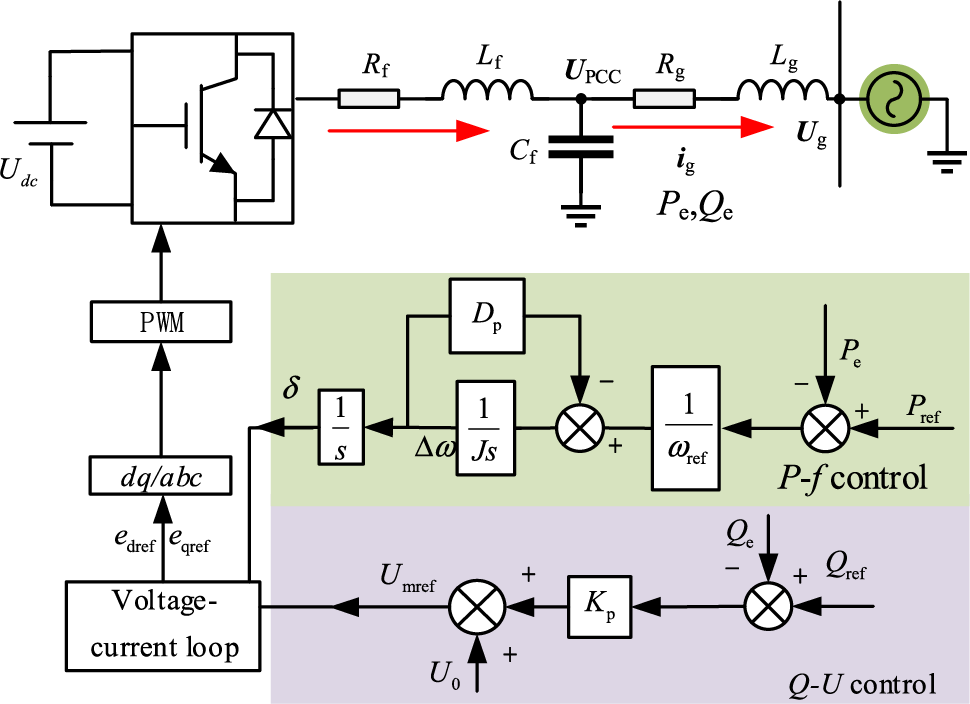
Figure 1: Virtual synchronous generator control block diagram
Generally, the power system satisfies the condition that Rg << Xg and the output power for traditional VSG control is shown as Eq. (1), and it shows that the decouple of active and reactive power control is achieved in the VSG.
As shown in Fig. 1, Eq. (2) can be obtained, which means that VSG simulates the rotor motion characteristics of the synchronous and can provide inertial and damping support to the grid:
where Δδ is the power angle difference, ωs is the control system angular frequency, ωg is the grid angular frequency, J is the virtual inertia, Dp is the virtual damping, Pref is the reference power, and Pe is the output active power.
The reactive power-voltage control in Fig. 1 simulates the droop characteristic between reactive power and voltage with the expression:
where U0 is the reference voltage, Kq is the reactive sag factor, Qref is the reference reactive power and Qe is the output reactive power.
2.2 Power Coupling Problems at High Grid Impedance Ratios
Since the time scales of the active loop and the reactive loop in VSG control are similar, the grid impedance exhibits resistance-inductance characteristics, and its impact of power coupling on control performance cannot be ignored. Assuming that the common point voltage Upcc is constant, the output power can be written as:
where ϕ is the grid impedance angle.
Finding the partial derivation of Eq. (4) Pe and Qe, Eq. (5) can be obtained:
As shown in Eq. (5), when the grid resistance Rg is large, there is a coupling relationship between active power and reactive power. Power angle δ is related to common point voltage, grid impedance, and other parameters. The coupling degree of active and reactive power increases as δ keeps increasing, thus the control performance of the VSG will be seriously affected.
3 Improved Transient Power Angle Stabilization Control Strategy for VSGs
The paper proposes an ImVSG transient power angle stabilization control (ImVSG) for VSG transient power angle stability under a high value of grid impedance ratio, namely R/X. The ImVSG is shown in Fig. 2, where PI control is introduced in the active power-frequency control link and fed back to the reactive power-voltage control link to improve the transient power angle stability of traditional VSG. Considering the situation that R/X is high, which usually happens in the medium and low voltage line, a virtual impedance is introduced to adjust the grid impedance ratio R/X to avoid power coupling and deterioration of power control performance.
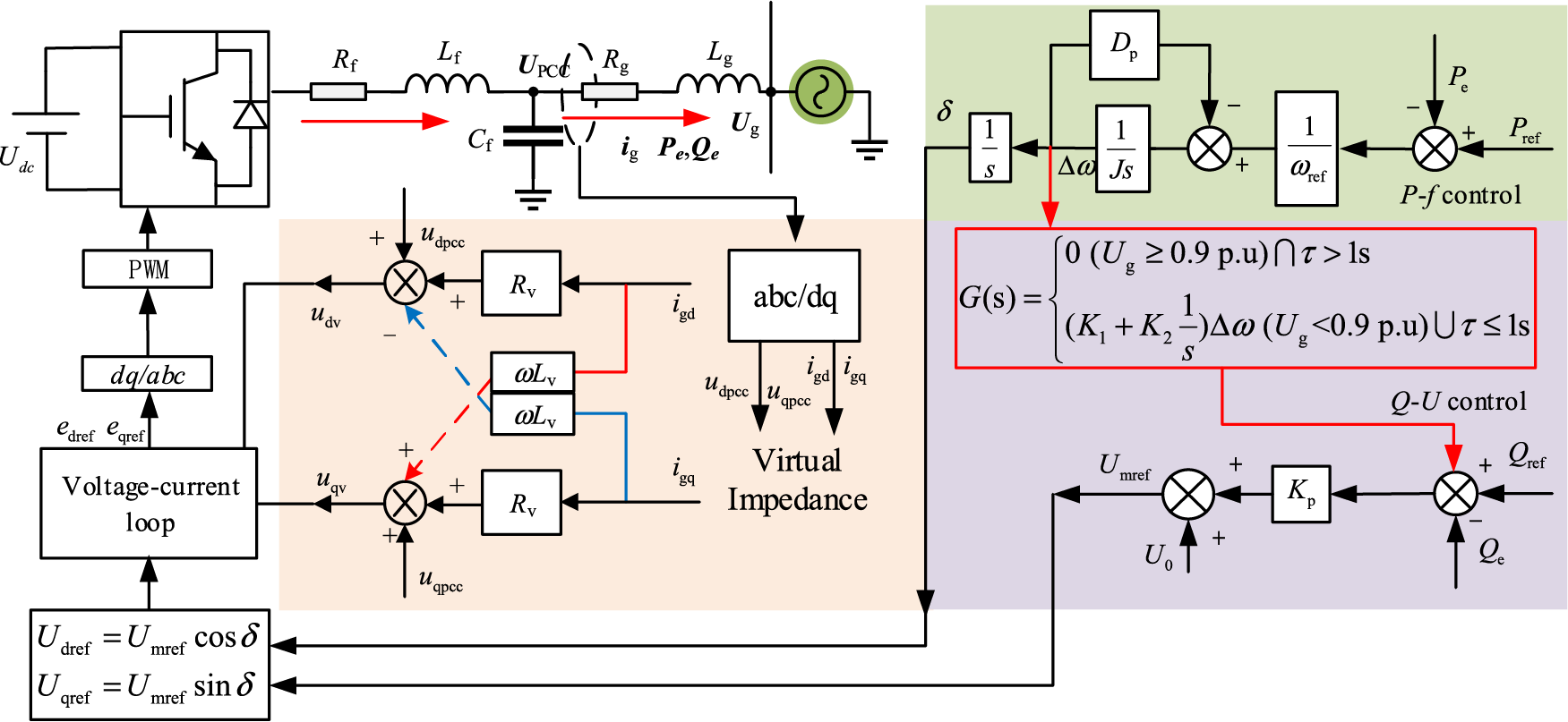
Figure 2: Improved VSG of transient power angle stabilization
As shown in Fig. 2a, the expression of G(s) is:
where K1 is the Δω feedback proportionality coefficient; K2 is the Δω feedback integral coefficient; τ is the clock duration after a large perturbation. When the voltage drops more than 0.1 p.u or the voltage rises more than 0.1 p.u, τ starts timing from zero. According to GB/T 37408-2019 standard [27], the threshold value of τ is set to 1 s. If τ exceeds 1.5 s timing is stopped and the PI controller (K1 + K2/s) needs to reset the position to zero before enabling it again.
From Eqs. (2) and (6), the reactive-voltage control of the ImVSG when the system suffers a large disturbance (in Fig. 2, when Ug is < 0.9 p.u) is:
Substituting Eq. (4) into (7) and approximating Umref = Upcc, Eq. (8) is obtained. And from Eq. (7), when the VSG is stabilized with Δδ = 0 and Δω = 0, the PI feedback link does not affect the steady state of the reactive-voltage control loop.
where a, b, c are as follows:
As shown in Fig. 2b, the expression of virtual impedance in the voltage loop is:
where udpcc and uqpcc are the dq component of Upcc, igd and igq are dq component of ig, Rv is virtual resistance, Lv is virtual inductance.
4 Effect of Grid Impedance Ratio on VSG Power Angle Stability
4.1 Effect of Different K1 and K2 on the Stability of the Power Angle
In this paper, the influence of impedance ratio is considered and the small-signal method is used to analyze the stability of small disturbances power angle at different K1 and K2 during VSG voltage drop. According to Eq. (1), the VSG second-order dynamic system expression can be simplified as:
Define the stable equilibrium point xe = [Δδe Δω] and the unstable equilibrium point xce = [Δδce Δω], linearize the VSG second-order dynamical system and the Jacobian matrix J(xe) is:
where J21 and J22 are shown in Eqs. (13) and (14).
According to Eqs. (4) and (7), the partial derivatives of Upcc(Δδ, Δω) with respect to Δδ and Δω are obtained as Eqs. (15) and (16).
The eigenvalue of Jacobian matrix J(xe) is:
λ1,2 determine the VSG system stability performance. From Eqs. (12)–(17), the proportional coefficient K1, integral coefficient K2 of frequency feedback, and grid resistance Rg all have an effect on the small-signal stability of the ImVSG control. Defining λ1,2 = −σ1, 2
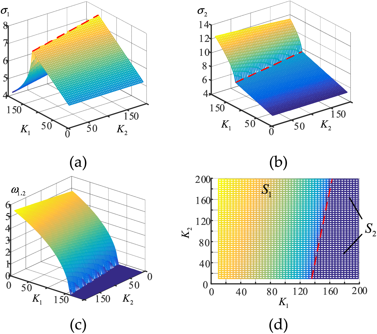
Figure 3: When Ug = 0.6 p.u, K1, K2 from 10 p.u to 200 p.u, (a) σ1 trajectory, (b) σ2 trajectory, (c) ω1,2 trajectory, (d) ω1,2 trajectory
4.2 Stability Analysis of Transient Power Angle with Different Impedance Ratios
According to Section 2.2, it is known that the magnitude of the grid impedance ratio affects the coupling degree of active and reactive power of VSG, thus the power angle stability will be affected. From Eq. (5), the maximum value of the output active power, which is called the active transmission limit, is:
The characteristic curve of Pmax-ϕ with constant impedance amplitude is shown in Fig. 4. It can be seen that when the grid impedance is of resistive-inductive characteristics, Pmax decreases with the impedance angle ϕ. The positive correlation between Pmax and the common point voltage Upcc indicates that a decrease in the Upcc means a decrease of Pmax, which will worsen stability performance.
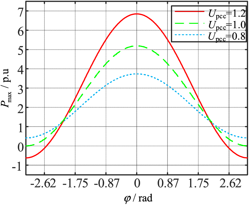
Figure 4: Characteristic curve of Pmax-ϕ
The variation of the R/X will cause changes in the Pmax when the VSG is connected to the grid, which will inevitably affect the transient power angle stability of the VSG. This article uses the equal area criterion to discuss and analyze the impact of the grid impedance ratio R/X on transient power angle stability.
In this paper, the VSG power angle and Upcc under a high grid impedance ratio are calculated by the algorithm as shown in Fig. 5, and the characteristic curves of P-δ are plotted under different impedance ratios R/X, as shown in Fig. 6. Fig. 6a shows that when R/X decreases, Pmax and the maximum deceleration area Smax increase. From Fig. 6b, the accelerating area Sup decreases and the decelerating area Sdown increases as R/X decreases during grid voltage dips, indicating that the decrease of R/X contributes to the enhancement of the transient power angle stability of the VSG.
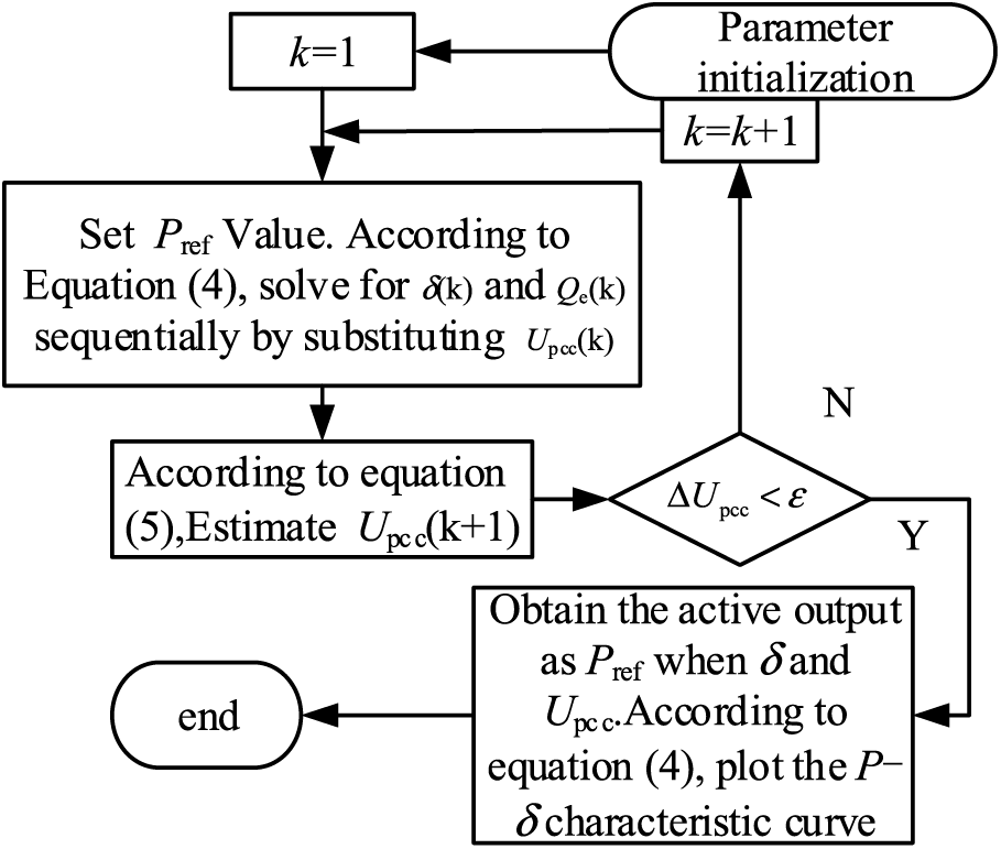
Figure 5: algorithm estimation P-δ considering power coupling
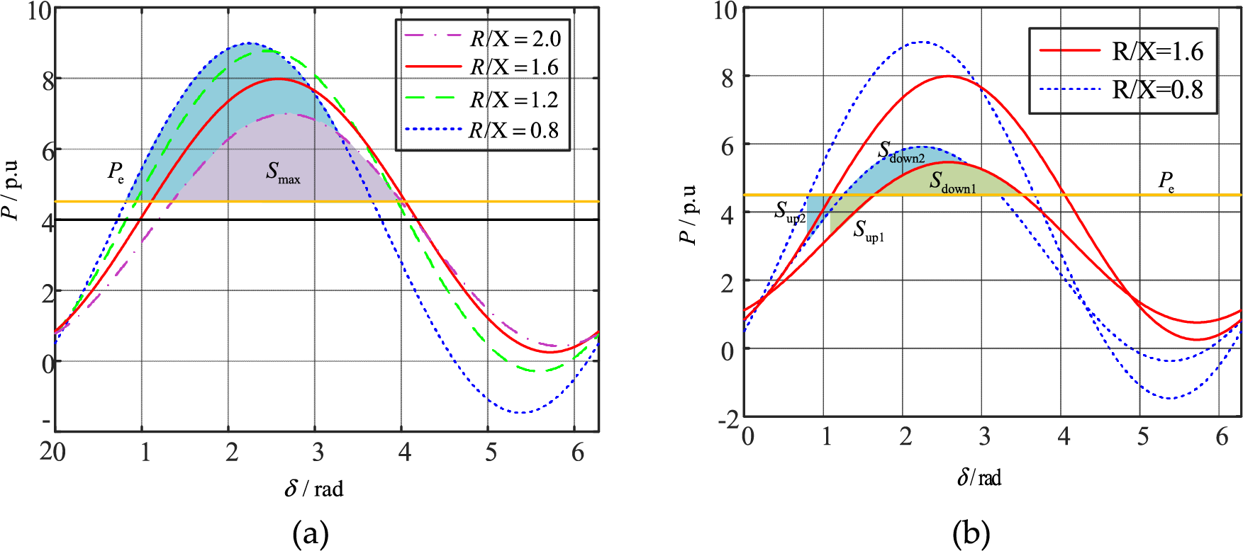
Figure 6: Characteristics of P-δ with various R/X (a) normal operation of VSG (b) grid voltage drop
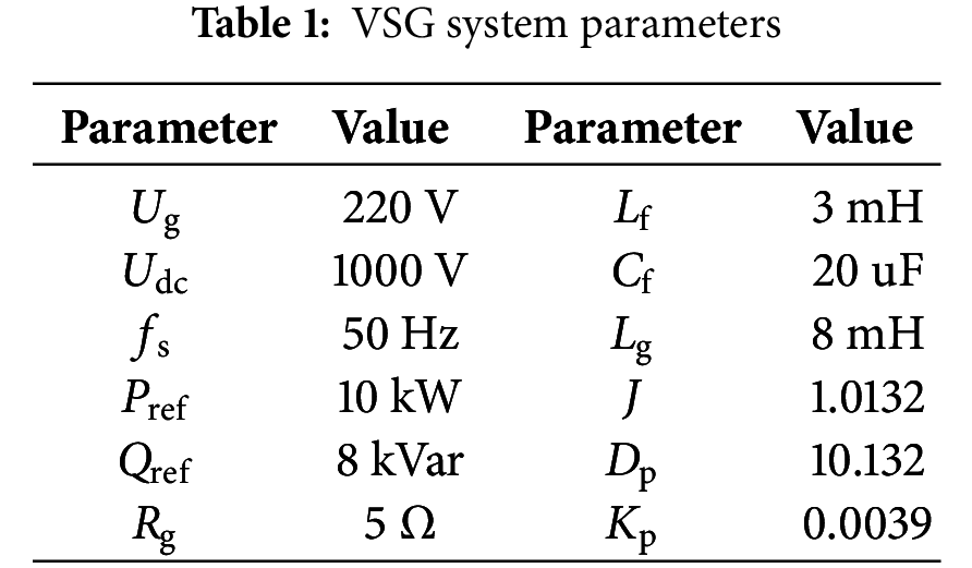
For the VSG system with grid impedance presenting resistive inductive characteristics, the proposed ImVSG control is quantitatively analyzed by comparing the simulation results with different values of K1, K2 and R/X. The simulation model is set to run at t = 5 s, and the voltage drops to 0.6 p.u at t = 6 s and recovers to 1 p.u at t = 8 s. The parameters used in the simulation are shown in Table 1.
5.1 Effect of K1 on the Stability of the Power Angle
Fig. 7a and Table 2 show that when the voltage falls from 1.0 to 0.6 p.u at t = 6 s, K1 changes from 0 to 200 p.u, and the maximum VSG frequency swing range decreases from Δf1 = 0.128 to Δf1 = 0.088 Hz. The power angle swing range Δδ1 decreases by 0.0259 rad, and the VSG quickly finds a new stable equilibrium point and regains the synchronization stability. From Fig. 7b and Table 2, when the voltage recovers to 1.0 p.u at t = 8 s, the maximum VSG frequency swing range decreases from Δf2 = 0.205 to Δf2 = 0.136 Hz as K1 increases from 0 to 200 p.u. Δf2 decreases from 0.205 to 0.136 Hz, Δδ 2 decreases by 0.053 rad, and VSG regains its original stable equilibrium point quickly after voltage recovery. Fig. 7c and Table 2 show that as K1 goes from 0 to 200 p.u, the active power overshoot σ1 decreases from 12.4% to 10.4% during the voltage dip, and the active power overshoot σ2 decreases from 18.5% to 21.2% during the voltage recovery, indicating that the increase of K1 is beneficial to suppress the power oscillation during large disturbances. Fig. 8a–c shows that K1 has no significant effect on the grid-connected current. The simulation results in Fig. 7 indicate that an appropriate increase in K1 can enhance the transient power angle stability, accelerate the convergence of VSG to the stable equilibrium point, and improve the power control performance.
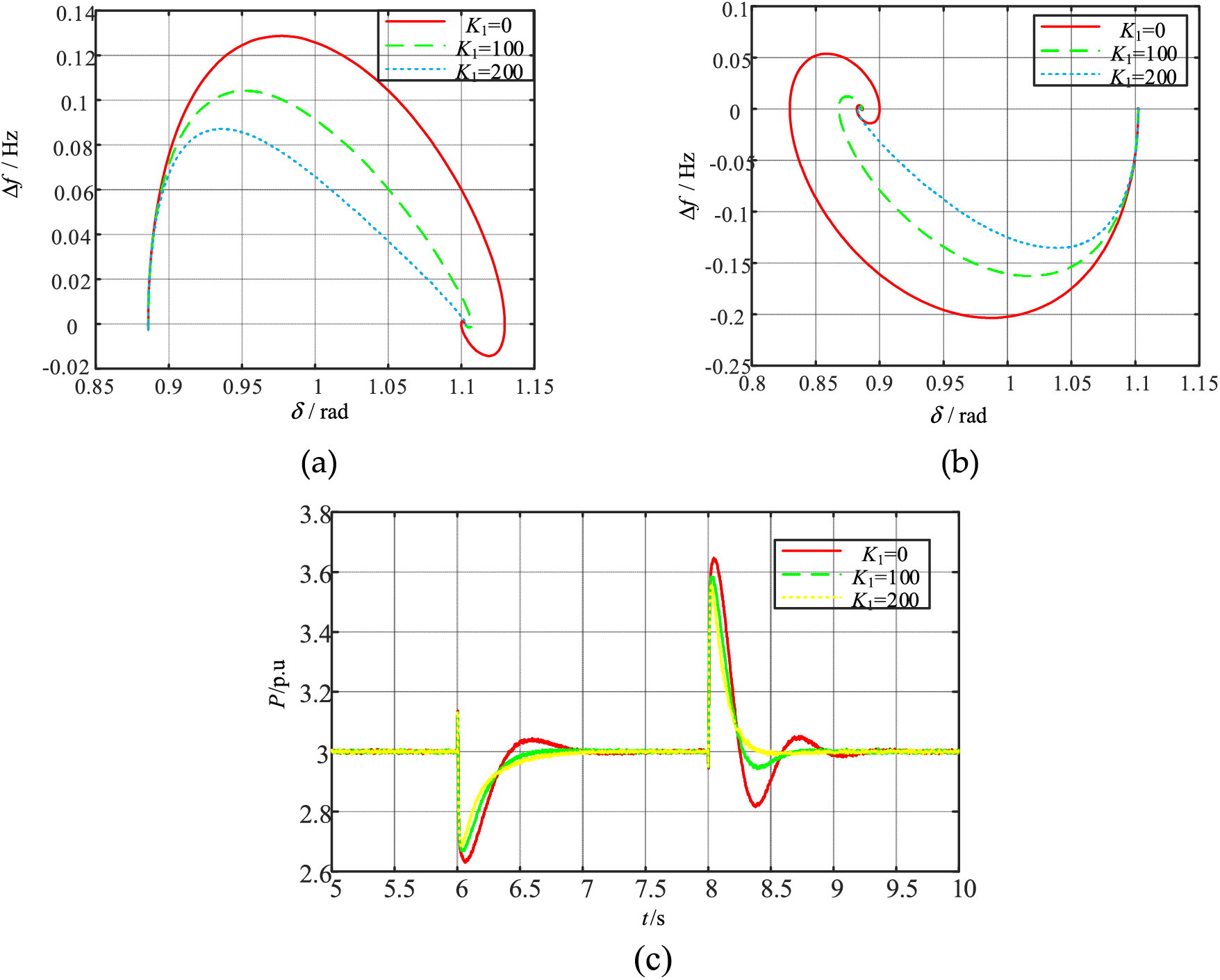
Figure 7: VSG responses for different K1 when large disturbances (a) frequency-power angle trajectory when voltage drop (b) frequency-power angle trajectory when voltage recovery (c) active power
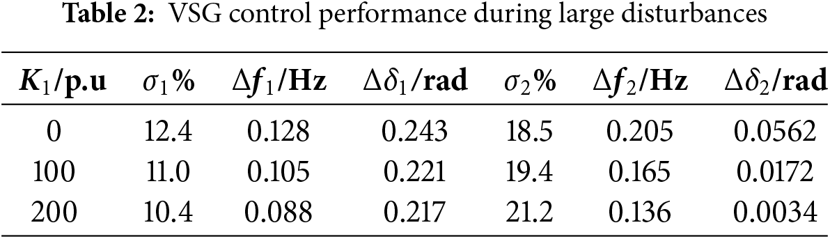
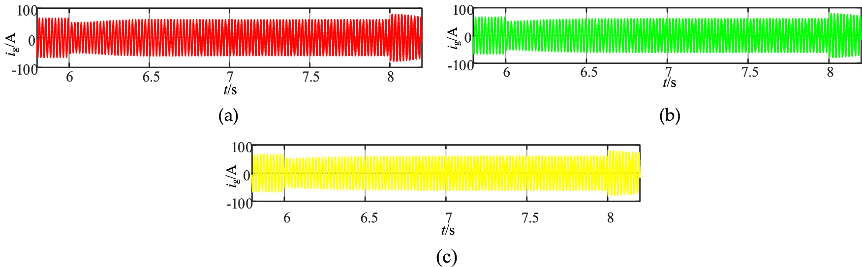
Figure 8: VSG grid-connecting current responses for different K1 when large disturbances (a) VSG grid-connecting current ig (K1 = 0 p.u) (b) VSG grid-connecting current ig (K1 = 100 p.u) (c) VSG grid-connecting current ig (K1 = 200 p.u)
5.2 Influence of the Integration Factor K2 on the Power Angle Stability
Fig. 9a and Table 3 show that when the voltage falls from 1.0 to 0.6 p.u at t = 6 s, as K2 goes from 0 to 200 p.u, the amplitude of the VSG power angle oscillations Δδ 1 decreases by 0.033 rad, and VSG converges to the new stable equilibrium point during the low voltage period. Fig. 9b and Table 3 show when the voltage recovers to 1.0 p.u at t = 8 s, K2 goes from 0 to 200 p.u, Δδ 2 decreases by 0.033 rad and the VSG restores the original stable equilibrium point. From Fig. 10a–c, it can be concluded that K2 has no significant effect on active power and VSG grid-connected current. Eq. (7) shows that the Δδ makes Upcc change, and K2 is positively correlated with Upcc. Fig. 11 shows that Upcc increases by 0.012 p.u with the increase of K2 when the grid voltage Ug = 0.6 p.u. As shown in Figs. 9 and 11, Δδ decreases with the increase of K2. The simulation results show that K2 increase during voltage dips can enhance the VSG synchronization stability.
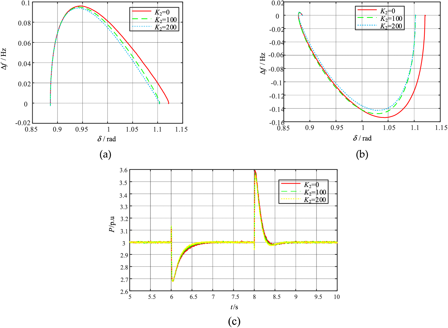
Figure 9: VSG responses for different K2 when large disturbances (a) frequency-power angle trajectory when voltage drop (b) frequency-power angle trajectory when voltage recovery (c) active power
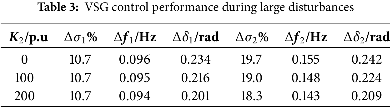
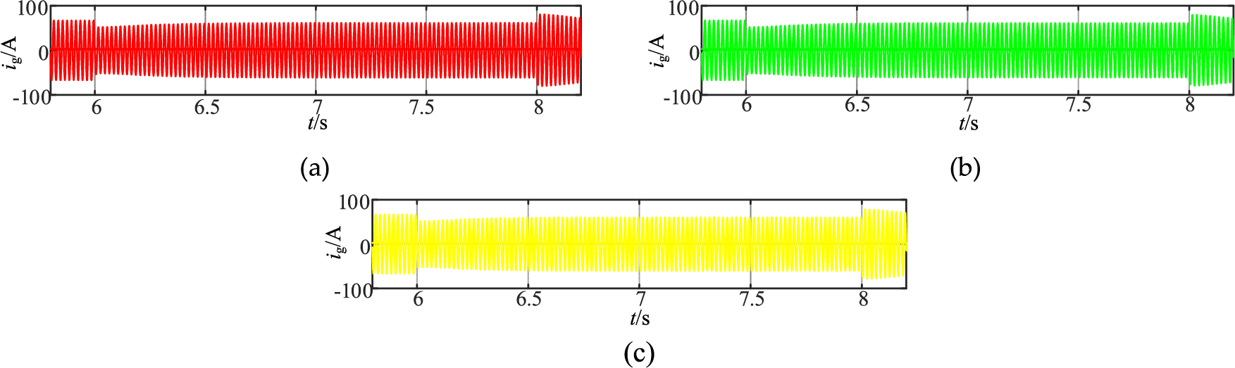
Figure 10: VSG grid-connecting current responses for different K2 when large disturbances (a) VSG grid-connecting current ig (K2 = 0 p.u) (b) VSG grid-connecting current ig (K2 = 100 p.u) (c) VSG grid-connecting current ig (K2 = 200 p.u)
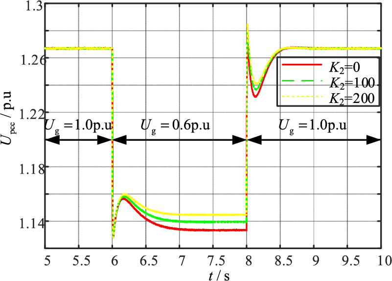
Figure 11: Upcc responses for different K2 when large disturbances
5.3 Influence of the Grid Impedance Ratio R/X on Power Angle Stability
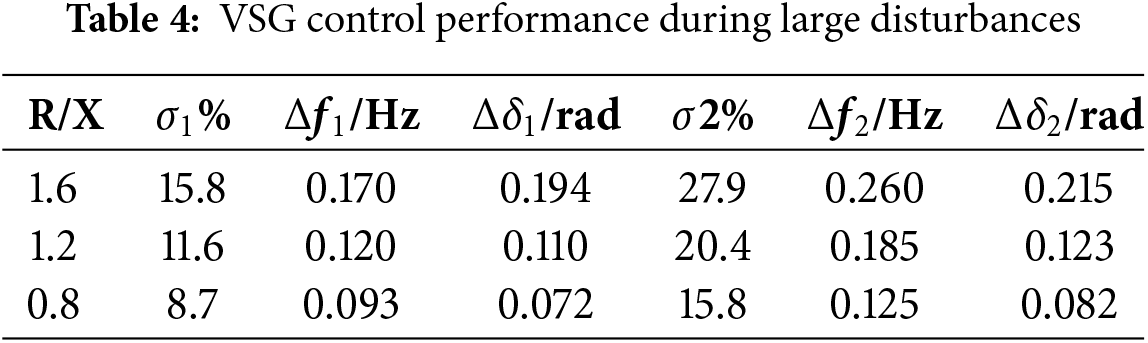
The proposed ImVSG control uses the PI control with K1 = 150 and K2 = 100 and it is compared with the conventional VSG with R/X = 2.0 and the VSG responses with different R/X during large disturbances are shown in Fig. 12, with xe1, xe2 and xe3 are the new equilibrium points during the low voltage period. From Fig. 12a and Table 4, it can be seen that the new stabilized equilibrium point xe1 > xe2 > xe3 is reduced from 2.0 to 0.8 due to the induced virtual impedance adjustment of R/X, and the transient power angle stabilizing control of both the conventional VSG and the VSG with R/X = 2.0 are both transient instability during the first power angle swing after a large perturbation. During the voltage dips with the reduction of R/X from 1.6 to 0.8, Δδ 1 is reduced from 0.194 rad to 0.072 rad, Δf 1 is reduced from 0.170 to 0.093 Hz. During the voltage recovery period, R/X decreases from 1.6 to 0.8, Δδ2 of VSG is reduced from 0.215 rad to 0.082 rad, and Δf2 decreases from 0.260 to 0.125 Hz. From Fig. 12b and Table 4, it can be seen that both the traditional VSG and the ImVSG with R/X = 2.0 have active oscillations diverging during the large perturbation period. When R/X decreases from 1.6 to 0.8, the active overshoot σ1 during the voltage dip decreases from 15.8% to 8.7%, and the active overshoot σ2 during voltage recovery decreases from 27.9% to 15.8%. Fig. 13a–e shows that the grid-connected current ig of the traditional VSG fluctuates drastically between 100 A and 26 A during Ug = 0.6 p.u. When R/X decreases from 2.0 to 0.8, the ig decreases from 1.35 times to 1.21 times of steady-state current during voltage restoration, which indicates that the overcurrent can be suppressed by adjusting R/X. Fig. 12 shows that a high impedance ratio deteriorates the transient power angle stability of VSG, and the use of virtual impedance to adjust R/X can reduce the Δδ of VSG during voltage dips, suppress active power oscillations, narrow the frequency fluctuation range, and enhance the transient power angle stability.
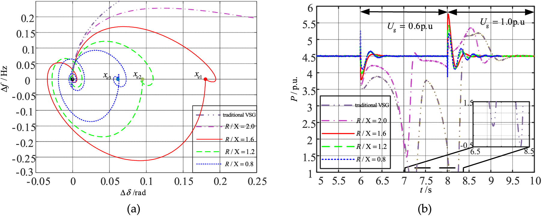
Figure 12: VSG responses for different R/X when large disturbances (a) frequency-power angle trajectory (b) active power
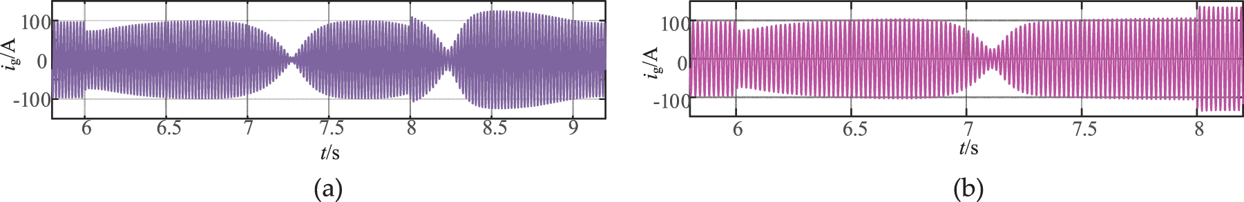
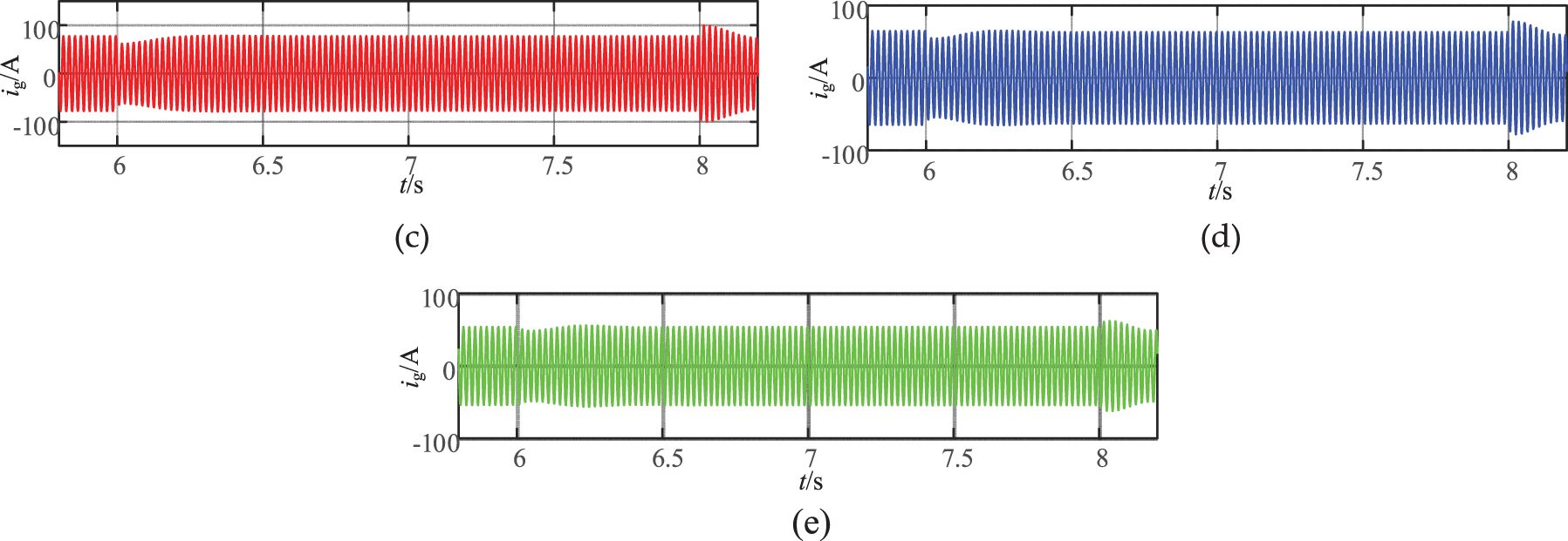
Figure 13: VSG grid-connecting current ig for different R/X when large disturbances (a) VSG grid-connecting current ig (conventional VSG, R/X = 2.0) (b) VSG grid-connecting current ig (ImVSG, R/X = 2.0) (c) VSG grid-connecting current ig (ImVSG, R/X = 1.6) (d) VSG grid-connecting current ig (ImVSG, R/X = 1.6) (e) VSG grid-connecting current ig (ImVSG, R/X = 1.6)
In this paper, an improved VSG (ImVSG) stabilization control strategy, which introduced a frequency difference feedback and a virtual negative impedance to address the problem of deterioration of transient power angle stability induced by large grid impedance ratio R/X, is proposed. The second-order dynamic VSG system mathematical model considering a reactive-voltage loop is established to analyze the small-signal stability at the stable equilibrium point. The transient power angle stability of VSG under different R/X is analyzed and verified by simulation results. The conclusions are as follows:
(1) The proposed ImVSG is theoretically analyzed in terms of the functional relationship between Upcc, Δδ and Δω under high grid impedance ratio R/X; the mathematical model of the second-order dynamic nonlinear VSG system considering the reactive-voltage loop is established, and the mathematical relationship between the control parameters and the characteristic roots is deduced.
(2) For the ImVSG proposed in this paper, the influence of parameters K1 and K2 on the stability of VSG is quantitatively analyzed. When K1 goes from 0 to 200 p.u, the active power overshoot σ1 decreases from 12.4% to 10.4% during the voltage dip, and the active power overshoot σ2 decreases from 18.5% to 21.2% during the voltage recovery, indicating that the increase of K1 is beneficial to suppress the power oscillation during large disturbances. When K2 goes from 0 to 200 p.u, the amplitude of the VSG power angle oscillations Δδ 1 decreases by 0.033 rad, and VSG converges to the new stable equilibrium point during the low voltage period, indicating that K2 increase during voltage dips can enhance the VSG synchronization stability. When the VSG is an underdamped system, K1 and K2 can strengthen the damping effect near the VSG stabilizing equilibrium point and improve the VSG stability; when the VSG is an overdamped system, K1 and K2 deteriorate the VSG stability.
(3) The higher the value of R/X, the weaker the transient power angle stability of the VSG. During the voltage dips with the reduction of R/X from 1.6 to 0.8, Δδ 1 is reduced from 0.194 rad to 0.072 rad, Δf 1 is reduced from 0.170 to 0.093 Hz, which shows better transient power angle stability. Reducing the impedance ratio R/X by the introduced virtual negative impedance can suppress the active power oscillation and improve the transient power angle stability effectively, the new stabilized equilibrium point is reduced from 2.0 to 0.8 due to the induced virtual impedance adjustment of R/X.
Acknowledgement: Xiao Yang is acknowledged for technical assistance in performing experiments.
Funding Statement: This work was supported by the Major Science and Technology Projects of China Southern Power Grid (Grant number CGYKJXM20210328).
Author Contributions: Conceptualization, Dianlang Wang, Qi Yin, Haifeng Wang and Jing Chen; Methodology, Yihan Chen, Haifeng Wang and Hong Miao; Software, Dianlang Wang, Yihan Chen and Qi Yin; Formal analysis, Dianlang Wang, Yihan Chen and Jing Chen; Investigation, Qi Yin and Jing Chen; Resources, Dianlang Wang and Haifeng Wang; Writing—original draft preparation, Dianlang Wang and Yihan Chen; Writing—review and editing, Yihan Chen and Hong Miao; Supervision, Qi Yin, Haifeng Wang and Hong Miao. All authors reviewed the results and approved the final version of the manuscript.
Availability of Data and Materials: Not applicable.
Ethics Approval: Not applicable.
Conflicts of Interest: The authors declare no conflicts of interest to report regarding the present study.
References
1. Gong RX, Gu JY. Adaptive control strategy of inertia and damping for load virtual synchronous machine. Electr Meas Instrum. 2023;60(3):130–5. doi:10.19753/j.issn1001-1390.2023.03.019. [Google Scholar] [CrossRef]
2. Zhu HM, Yuan S, Li CL. Control strategy and analysis of virtual synchronous generator of photovoltaic power plant with energy storage link. Electr Meas Instrum. 2023;60(5):45–50. doi:10.19753/j.issn1001-1390.2023.05.006. [Google Scholar] [CrossRef]
3. Chen M, Zhou D, Blaabjerg F. Enhanced transient angle stability control of grid-forming converter based on virtual synchronous generator. IEEE Trans Ind Electron. 2022;69(9):9133–44. doi:10.1109/TIE.2021.3114723. [Google Scholar] [CrossRef]
4. Zhang Y, Cai X, Zhang C. Transient synchronization stability analysis of voltage source converters: a review. Proc CSEE. 2021;41(5):1687–702. doi:10.13334/j.0258-8013.pcsee.201673. [Google Scholar] [CrossRef]
5. Zhang Y, Cai X, Zhang C. Transient grid-synchronization stability analysis of grid-tied voltage source converters: stability region estimation and stabilization control. Proc CSEE. 2022;42(21):7871–84. doi:10.13334/j.0258-8013.pcsee.211148. [Google Scholar] [CrossRef]
6. Ge PJ, Tu CM. Transient stability enhancement of a VSG based on flexible switching of control parameters. Proc CSEE. 2022;42(6):2109–24. doi:10.13334/j.0258-8013.pcsee.210915. [Google Scholar] [CrossRef]
7. Saffar KG, Driss S, Ajaei FB. Impacts of current limiting on the transient stability of the virtual synchronous generator. IEEE Trans Power Electron. 2023;38(2):1509–21. doi:10.1109/TPEL.2022.3208800. [Google Scholar] [CrossRef]
8. Shuai Z, Shen C, Liu X, Li Z, Shen ZJ. Transient angle stability of virtual synchronous generators using Lyapunov’s direct method. IEEE Trans Smart Grid. 2018;10(4):4648–61. doi:10.1109/TSG.2018.2866122. [Google Scholar] [CrossRef]
9. Cheng H, Shuai Z, Shen C, Liu X, Li Z, Shen ZJ. Transient angle stability of paralleled synchronous and virtual synchronous generators in islanded microgrids. IEEE Trans Power Electron. 2020;35(8):8751–65. doi:10.1109/TPEL.2020.2965152. [Google Scholar] [CrossRef]
10. Tang YJ, Zha XM. Transient stability analysis of virtual synchronous generator and SVG parallel system under weak grid conditions. Power Syst Technol. 2022;46(10):4020–34. doi:10.13335/j.1000-3673.pst.2021.1901. [Google Scholar] [CrossRef]
11. Li XL, Wang Z. Transient stability analysis of PLL synchronization in weak-grid-connected VSCs based on the largest estimated domain of attraction. Proc CSEE. 2022;42(20):7485–97. doi:10.13334/j.0258-8013.pcsee.211899. [Google Scholar] [CrossRef]
12. Dang K, Tian Y. Study on improving LVRT capability and power angle stability of VSG by series braking resistor. Acta Energ Sol Sin. 2022;43(1):323–8. doi:10.19912/j.0254-0096.tynxb.2020-0081. [Google Scholar] [CrossRef]
13. Sun R, Ma J, Yang W, Wang S, Liu T. Transient synchronization stability control for LVRT with power angle estimation. IEEE Trans Power Electron. 2021;36(10):10981–5. doi:10.1109/TPEL.2021.3070380. [Google Scholar] [CrossRef]
14. Xiong X, Wu C, Cheng P, Blaabjerg F. An optimal damping design of virtual synchronous generators for transient stability enhancement. IEEE Trans Power Electron. 2021;36(10):11026–30. doi:10.1109/TPEL.2021.3074027. [Google Scholar] [CrossRef]
15. Wu H, Wang X. A mode-adaptive power-angle control method for transient stability enhancement of virtual synchronous generators. IEEE J Emerg Sel Top Power Electron. 2020;8(2):1034–49. doi:10.1109/JESTPE.2020.2976791. [Google Scholar] [CrossRef]
16. Chen TY, Chen LJ, Zhen TW. LVRT control method of virtual synchronous generator based on mode smooth switching. Power Syst Technol. 2016;40(7):2134–40. doi:10.13335/j.1000-3673.pst.2016.07.030. [Google Scholar] [CrossRef]
17. Shi K, Ye HH, Xu PF. Low-voltage ride through control Strategy of virtual synchronous generator based on the analysis of excitation state. IET Gener Transm Distrib. 2018;12(9):2165–72. doi:10.1049/iet-gtd.2017.1988. [Google Scholar] [CrossRef]
18. Li QH, Ge PJ. Study on fault ride-through method of VSG based on power angle and current flexible regulation. Proc CSEE. 2020;40(7):2071–80+2387. doi:10.13334/j.0258-8013.pcsee.191684. [Google Scholar] [CrossRef]
19. Zhang YY, Zhao JB. VSG fault crossing method based on dynamic compensation of power angle. Power Syst Technol. 2021;45(9):3667–73. doi:10.13335/j.1000-3673.pst.2020.1624. [Google Scholar] [CrossRef]
20. Xiong X, Wu C, Hu B, Pan D, Blaabjerg F. Transient damping method for improving the synchronization stability of virtual synchronous generators. IEEE Trans Power Electron. 2021;36(7):7820–31. doi:10.1109/TPEL.2020.3046462. [Google Scholar] [CrossRef]
21. Xiong X, Wu C, Blaabjerg F. An improved synchronization stability method of virtual synchronous generators based on frequency feedforward on reactive power control loop. IEEE Trans Power Electron. 2021;36(8):9136–48. doi:10.1109/TPEL.2021.3052350. [Google Scholar] [CrossRef]
22. Aziz A, Qays MO, Jawad A, Ishraq Faruqui MF, Hossain ML, Kobeissi A. Optimal placement and sizing of synchronous condenser to enhance system strength of a renewable energy integrated weak grids. In: Proceeding of the EICT; 2023; Khulna, Bangladesh. doi: 10.1109/EICT61409.2023.10427908. [Google Scholar] [CrossRef]
23. Gao F, Iravan MR. A control strategy for a distributed generation unit in grid-connected and autonomous modes of operation. IEEE Trans Power Deliv. 2008;23(2):850–9. doi:10.1109/TPWRD.2007.915950. [Google Scholar] [CrossRef]
24. Shintai T, Miura Y, Ise T. Oscillation damping of a distributed generator using a virtual synchronous generator. IEEE Trans Power Deliv. 2014;29(2):668–76. doi:10.1109/TPWRD.2013.2281359. [Google Scholar] [CrossRef]
25. Chen S, Sun Y, Han H, Fu S, Luo S, Shi G. A modified VSG control scheme with virtual resistance to enhance both small-signal stability and transient synchronization stability. IEEE Trans Power Electron. 2023;38(5):6005–14. doi:10.1109/TPEL.2023.3243025. [Google Scholar] [CrossRef]
26. Zeng CB, Li SD, Wang HW, Miao H. A frequency adaptive scheme based on newton structure of PRRC for LCL-type inverter connected with weak grid. Energies. 2021;14(14):4225. doi:10.3390/en14144225. [Google Scholar] [CrossRef]
27. Wang LW, Miao H. The improved control method of parallel microgrid inverters. In: Proceeding of the ICPSPE; 2023; Nanchang, China. doi:10.1088/1742-6596/2564/1/012035. [Google Scholar] [CrossRef]
Cite This Article
 Copyright © 2025 The Author(s). Published by Tech Science Press.
This work is licensed under a Creative Commons Attribution 4.0 International License , which permits unrestricted use, distribution, and reproduction in any medium, provided the original work is properly cited.
 Downloads
 Citation Tools