
 Submit a Paper
 Propose a Special lssue
 Open Access
ARTICLE

Doubly-Fed Pumped Storage Units Participation in Frequency Regulation Control Strategy for New Energy Power Systems Based on Model Predictive Control
School of Electrical Engineering, Northeast Electric Power University, Jilin, 132012, China
* Corresponding Author: Yuanxiang Luo. Email:
Energy Engineering 2025, 122(2), 765-783. https://doi.org/10.32604/ee.2024.058426
Received 12 September 2024; Accepted 12 November 2024; Issue published 31 January 2025
 View Full Text
 Download PDF
Abstract
Large-scale new energy grid connection leads to the weakening of the system frequency regulation capability, and the system frequency stability is facing unprecedented challenges. In order to solve rapid frequency fluctuation caused by new energy units, this paper proposes a new energy power system frequency regulation strategy with multiple units including the doubly-fed pumped storage unit (DFPSU). Firstly, based on the model predictive control (MPC) theory, the state space equations are established by considering the operating characteristics of the units and the dynamic behavior of the system; secondly, the proportional-differential control link is introduced to minimize the frequency deviation to further optimize the frequency modulation (FM) output of the DFPSU and inhibit the rapid fluctuation of the frequency; lastly, it is verified on the Matlab/Simulink simulation platform, and the results show that the model predictive control with proportional-differential control link can further release the FM potential of the DFPSU, increase the depth of its FM, effectively reduce the frequency deviation of the system and its rate of change, realize the optimization of the active output of the DFPSU and that of other units, and improve the frequency response capability of the system.Graphic Abstract
Keywords
Nomenclature
| DFPSU | Doubly-fed pumped storage unit |
| FM | Frequency modulation |
| MPC | Model predictive control |
| AI | Artificial insemination |
| PV | Photovoltaic |
| AMPC | Adaptive model predictive control |
| SOC | State of charge |
| WTG | Wind turbine generator |
With the increasing proportion of new energy in the power system, the traditional synchronous units can not provide sufficient frequency support for the system, the rotational inertia level of the system is reduced, and the problem of frequency security is becoming more and more prominent [1–4]. Accidents such as distributed power off-grid and low-frequency load shedding due to insufficient inertia support capacity have already occurred in the power systems of many countries [5–7]. Under the low inertia power system, new problems and risks may appear in conventional operation and control methods [8]. Therefore, there is an urgent need to accelerate the construction of power systems to improve new energy consumption and reduce the dependence on traditional units [9–11].
Pumped storage units have become the first choice of energy storage equipment for power systems because of their large capacity, low cost, and unlimited energy storage cycles [12–15]. However, traditional pumped storage units need help with a small power adjustable range and slow response speed, which cannot meet the demands of new power systems. In contrast, the variable speed of DFPSUs can operate at the optimal speed according to the power command of the grid, which enhances the power regulation capability and dramatically alleviates the problem of insufficient primary FM energy brought by the high penetration rate of new energy [16–19]. However, the existing studies cannot make the rotor speed respond quickly to the frequency change. Therefore, it is significant to release the latent inertia of DFPSUs by conducting an in-depth study on their frequency control strategy.
At present, the large-scale access to the system by new energy units represented by wind power makes the penetration rate of wind power in the system increase, and the frequency stability of the power system cannot be guaranteed by relying on the DFPSU only to complete the system frequency regulation task. Meanwhile, artificial insemination (AI) algorithms are constantly applied to new energy units in power forecasting, scheduling optimization, and active power optimization [20]. In the power system, the units involved in frequency regulation must fully consider the constraints of active output to ensure that their output power does not exceed the specified limits. MPC shows significant advantages in dealing with multivariate constraints [21–23], so many researchers and scholars tend to adopt MPC control methods to optimize the active output of each unit. Literature [24] is based on MPC to achieve the coordination between thermal power units and energy storage devices to complete the FM mission and optimize the active power output. Literature [25] proposes a method for wind turbine participation in system frequency control based on MPC inverter interface to ensure that the low inertia power system frequency operates within a safe range. Literature [26] uses MPC control to effectively regulate system frequency by modeling a new energy-combined power plant. Literature [27] proposes an adaptive MPC (AMPC) frequency regulation strategy for a simplified prediction model of a DFPSU, which effectively reduces the maximum frequency deviation of the system. The above studies have mainly focused on exploring power system frequency regulation using MPC technology. However, these studies have yet to fully explore and utilize the potential advantages and application value of DFPSU in multi-unit joint frequency regulation.
This paper proposes a frequency regulation control strategy considering frequency deviation and its rate of change in a large-scale grid-connected scenario of new energy units. The strategy is based on the MPC theory, constructs the overall state space equation of the system, and introduces the proportional-differential control link in the control strategy to release the potential inertia of the DFPSU. The MATLAB/Simulink simulation experiment proves that the strategy proposed in this paper can effectively suppress the rapid frequency fluctuation and improve the frequency response capability of the system.
2 Power System Model Based on MPC
For the problem of system frequency fluctuation caused by changes in load and PV power plant output, the MPC calculates the reference power change amount according to the current and future predicted grid frequency, taking into account the operating status of each FM unit at that moment, to improve the effect of the system FM, and complete the optimal distribution of active power among the units in the system.
The new frequency response model in energy power systems based on model prediction is shown in Fig. 1, which mainly includes conventional units, DFPSUs, wind power units, photovoltaic power plants, lithium battery storage devices, model prediction controllers, and loads, with additional proportional-differential control links that consider the frequency deviation and its rate of change. In the figure, the MPC controller performs rolling optimization calculations and issues active power commands based on the operating status of each of the above units ΔPgk, ΔPhk, ΔPsk, ΔPbk, ΔPwk, and each unit receives and executes the control commands to optimize the active output and to adjust the active power deficit of the system.
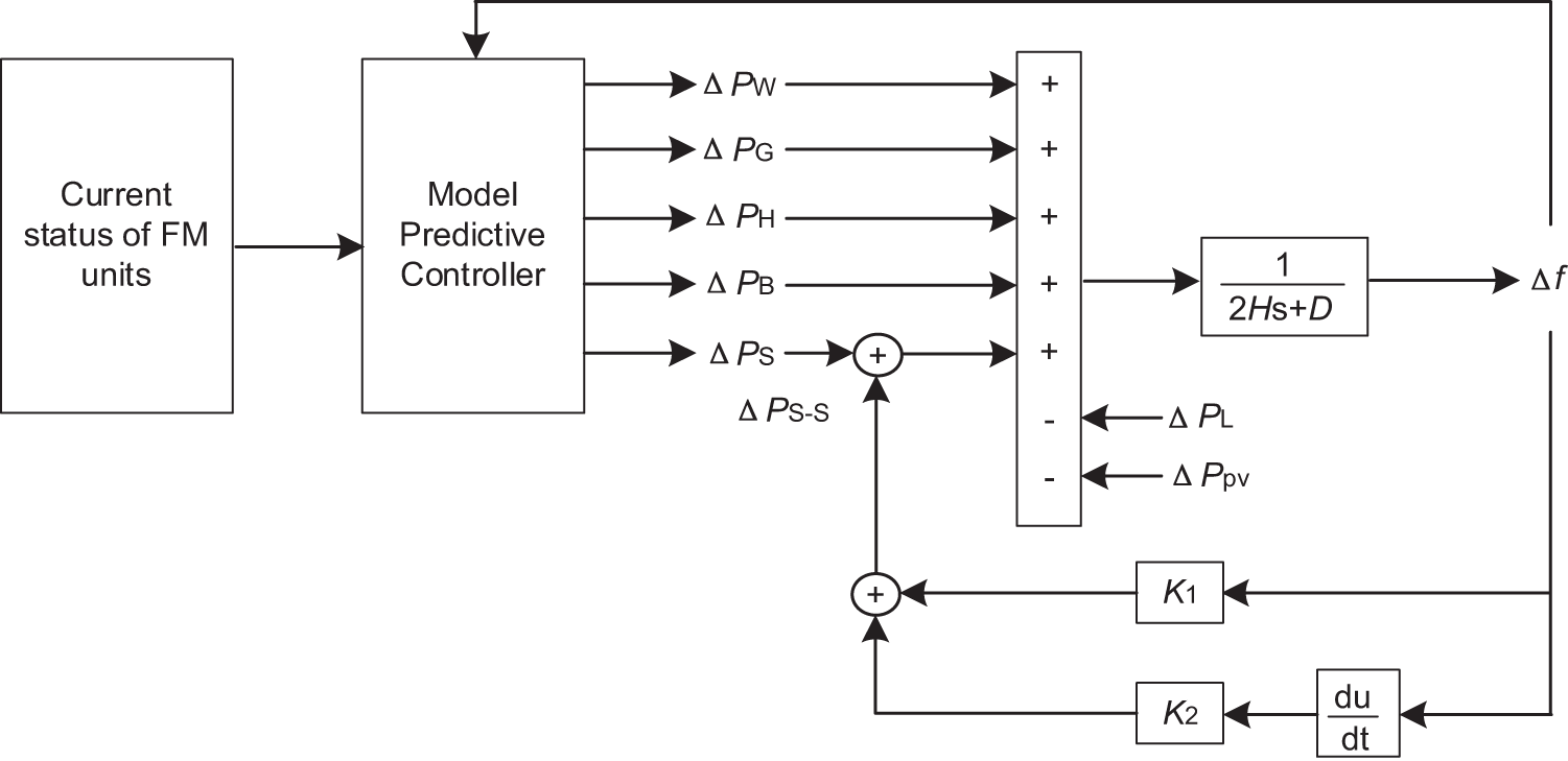
Figure 1: New energy power system frequency response model
The frequency dynamic model containing wind farms and photovoltaic plants is expressed as:
where Δf is the actual frequency deviation, with 50 Hz as the reference value; H is the system inertia constant; D is the load regulation coefficient; PL is the load power; PG, PH, PS, PB and PW are the power provided by thermal power units, hydroelectric power units, DFPSUs, lithium battery storage devices, and wind turbines, respectively; and ΔPpv is the fluctuation of the PV power plant active output.
3.1 Power System State Space Equations
The mathematical model of a reversible pump turbine operating in the turbine state can be expressed as:
where μs is the turbine guide vane opening;
The model of the diversion system accounting for the rigid water strike effect is expressed as:
where h is the head height; q is the turbine flow rate; Tω is the water flow inertia time constant.
The incremental form of the rigid water strike model for the turbine guide vane opening adjustment system under ideal operating conditions is:
where Ty is the time constant of the follower system; us is the turbine regulator output control quantity.
The mathematical model of the doubly-fed generator is expressed as
where
Synthesizing Eqs. (2), (4) and (5) The derivation leads to the equation of state of the DFPSU as:
where As and Bs are the matrix coefficients of DFPSUs, see Appendix A for details.
3.1.2 Modeling of Conventional Units
The first-order model is used for the thermal unit prime mover with the expression [21]:
where
The governor control uses proportional control with the expression:
where ug is the turbine regulator output control quantity; ωg is the generator rotor angular velocity; R is the unit modulation coefficient.
The thermal unit generator model can be expressed as:
where Hg, eg for thermal power unit inertia constants and damping coefficients;
The synthesis of Eqs. (8)–(10) derivation leads to the equation of state of thermal power unit as:
where Ag and Bg are the thermal unit coefficient matrices, see Appendix A for details.
The turbine and diversion system in the prime mover model of the hydropower unit are represented by Eqs. (2) and (3), respectively.
The hydraulic turbine guide vane hydraulic receiver model expression is:
where uh is the output control signal of the turbine governor of the hydropower unit; Yh is the opening degree of the hydraulic turbine guide vane of the hydropower unit.
The generator rotor equation of motion can be expressed as:
where Hh, eh are the inertia constant and damping coefficient of the hydropower unit;
The synthesized Eqs. (2), (3), (12), and (13) can be deduced to obtain that the state equation of the hydropower unit is:
where Ah and Bh are the matrix coefficients of the hydroelectric units, see Appendix A for details.
3.1.3 Modeling of Lithium Battery Storage Devices and Wind Turbine
The lithium battery energy storage device becomes an important means of frequency regulation, which is modeled as:
where Pbess is the actual output mechanical power; Pb.ref is the target value of the output power; TB is the energy storage response time constant.
The output mechanical power of the wind turbine is expressed as:
where
The generator rotor equation of motion can be expressed as:
where Hw, F are the inertia constant and damping coefficient;
Combining Eqs. (7), (11), (14)–(17) yields the system state-space equations as shown in Eq. (18) containing each FM unit:
where the state variables are included:
Control variables include:
Perturbation variables include:
3.2 Objective Function and Constraints
In the new energy power system for primary frequency regulation, the controller needs to meet the following requirements: through the MPC controller accurately tracking the frequency regulation signal and obtain the optimal control amount of each frequency regulation unit to complete the distribution of active power and minimize the actual grid frequency deviation, the objective function is set as follows:
In the formula, k + j|k represents the prediction of the state quantity at k moments for k + j moments; γ1, γ2, γ3, γ4, γ5 and γ6 are the weighting coefficients in the objective function, and the magnitude of its value represents the degree of punishment for this item; j, j − 1 represent the prediction and control time domain.
3.2.2 Constraints for Each FM Unit
In order to ensure the reasonableness of active power output when each FM unit participates in system FM, the active power output variation constraint is added to each unit, where variables with min and max in their subscripts represent their maximum and minimum values.
The constraint on the amount of change in the active output of a thermal unit can be expressed as:
where ΔPeg (k + j|k) denotes the predicted value of the active power control quantity of the thermal power unit at the k moment for the k + j moment.
The constraint on the amount of change in the active output of a hydroelectric unit participating in a primary FM can be expressed as:
where ΔPeh (k + j|k) denotes the predicted value of the active power control quantity of the hydroelectric unit at the moment k for the moment k + j.
The constraint on the change in active output of the DFPSU is expressed as:
where ΔPes (k + j|k) denotes the predicted value of the active power control quantity of the DFPSU at the moment k for the moment k + j.
It is necessary to set a constraint on the state of charge (SOC) of the battery to avoid overcharging and discharging, which can be expressed as:
where EB (k + j|k) denotes the predicted value of the lithium battery state of charge at k moments for k + j moments.
The battery energy storage device is used in practice with a charging and discharging power constraint to ensure safe operation:
where
The constraint on the change in active output of the wind turbine participating in the primary FM can be expressed as:
where ΔPeg (k + j|k) denotes the predicted value of the active power control of the wind turbines at the k moment for the k + j moment.
The wind turbine participates in the primary FM paddle pitch angle variation constraint as:
where β0 is the initial value of the wind turbine pitch angle; and Δβref (k + j|k) represents the predicted value at the k moment for the k + j moment.
3.3 Proportional-Differential Control Link for DFPSUs
The grid connection of large-scale new energy units reduces system inertia and weakens the units’ ability to respond to system frequency changes. To fully utilize the frequency regulation potential of DFPSUs, a proportional-differential control link should be added to them.
The FM auxiliary power of a DFPSU with a proportional-differential control link is:
where K1 and K2 are the coefficients of the frequency deviation value and its rate of change, respectively.
Define K1 as the active FM coefficient of a DFPSU, which is expressed as:
where ΔP, Δf and ΔP*, Δf* are the nominal and standardized values of active change and frequency deviation, respectively; σ* is the standardized value of turbine modulation coefficient; PN − S is the rated power of DFPSU; fN is the rated frequency of the system.
Define K2 as the inertia response coefficient of a DFPSU, and the rectification process is as follows.
Neglecting the damping effect, the rotational kinetic energy stored in the rotor of the DFPSU is:
where JS is the rotational inertia of the DFPSU; ωr is the rotor speed.
The active power ΔPd released or absorbed by the rotor kinetic energy when the system frequency is disturbed is:
The inertia time constant of a DFPSU is expressed as:
where SN − S is the rated capacity of the DFPSU.
Based on the equivalence relationship:
Considering the range of system frequency fluctuation, it can be approximated as ωr ≈ ωs, which is obtained by the coupling of Eqs. (33)–(35):
When the system frequency fluctuates and the angular velocity of the rotor of the DFPSU ωr0 changes to ωr, the kinetic energy ΔEk − S released by the rotor is:
where Jvir is the equivalent virtual moment of inertia of the DFPSU.
From the above equation, the equivalent inertia of the DFPSU virtualized with respect to the system frequency change is:
The rotational kinetic energy stored in the rotor of a wind turbine is:
where JW is the rotational inertia of the wind turbine; ωw − r is the rotor speed of the turbine.
When the system frequency fluctuates and the angular velocity of the wind turbine rotor ωw − 0 changes to ωw − r, the kinetic energy ΔEk − W released by the rotor is:
where Jvir.w is the equivalent virtual moment of inertia of the wind turbine.
From the above equation, the equivalent inertia of the wind turbine virtualized with respect to the system frequency change is:
With the introduction of the proportional-differential control link, the power system inertia is provided by DFPSUs, conventional synchronous units and wind turbines, and the system inertia time constant Htot is denoted as:
where m, n and q are the numbers of DFPSUs, synchronous units and wind turbine s, respectively; Jvir.j is the virtual moment of inertia of the jth DFPSU; Ji is the moment of inertia of the ith synchronous unit; Jvir.p is the virtual moment of inertia of the pth wind turbine; SN is the sum of the rated capacities of the units in the system.
In the previous section, a system prediction model with multiple constraints is developed to optimize the active output allocation of each FM unit involved in FM. The model solution flow is shown in Fig. 2:
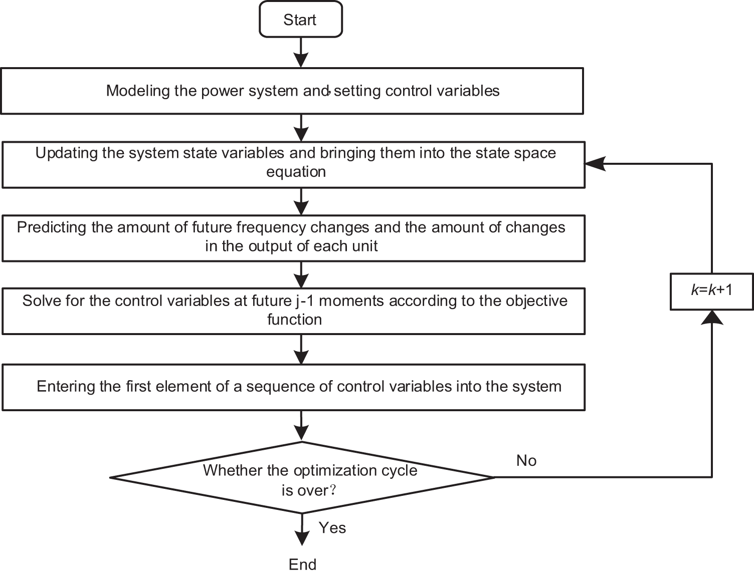
Figure 2: New energy power system MPC flowchart
Step 1: Based on the MPC theory, establish the state-space equations;
Step 2: Obtain the grid frequency deviation at the moment k, update the system state variables, and substitute them into the system state space equation;
Step 3: Based on the state information of the system at time k, predict the amount of change in the output of each unit at the following j times;
Step 4: With the objective function of minimizing the frequency deviation of the power system, a rolling optimization calculation is performed to solve for the active output command that satisfies the constraints at j − 1 future moments;
Step 5: Each unit in the system participating in FM receives and responds to the active output command to release active power.
5 System Simulation and Verification
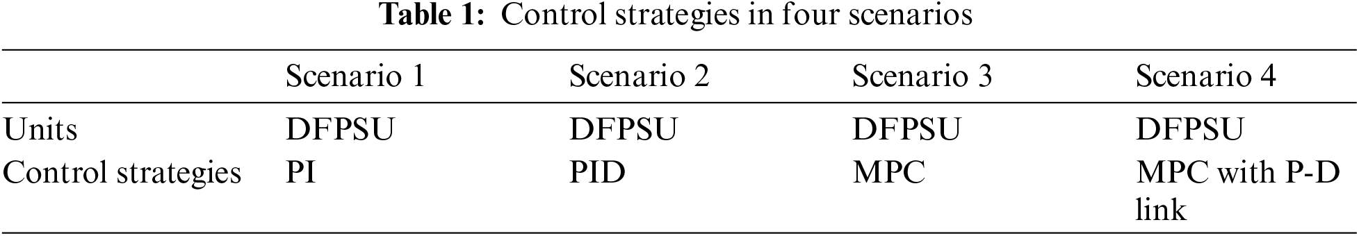
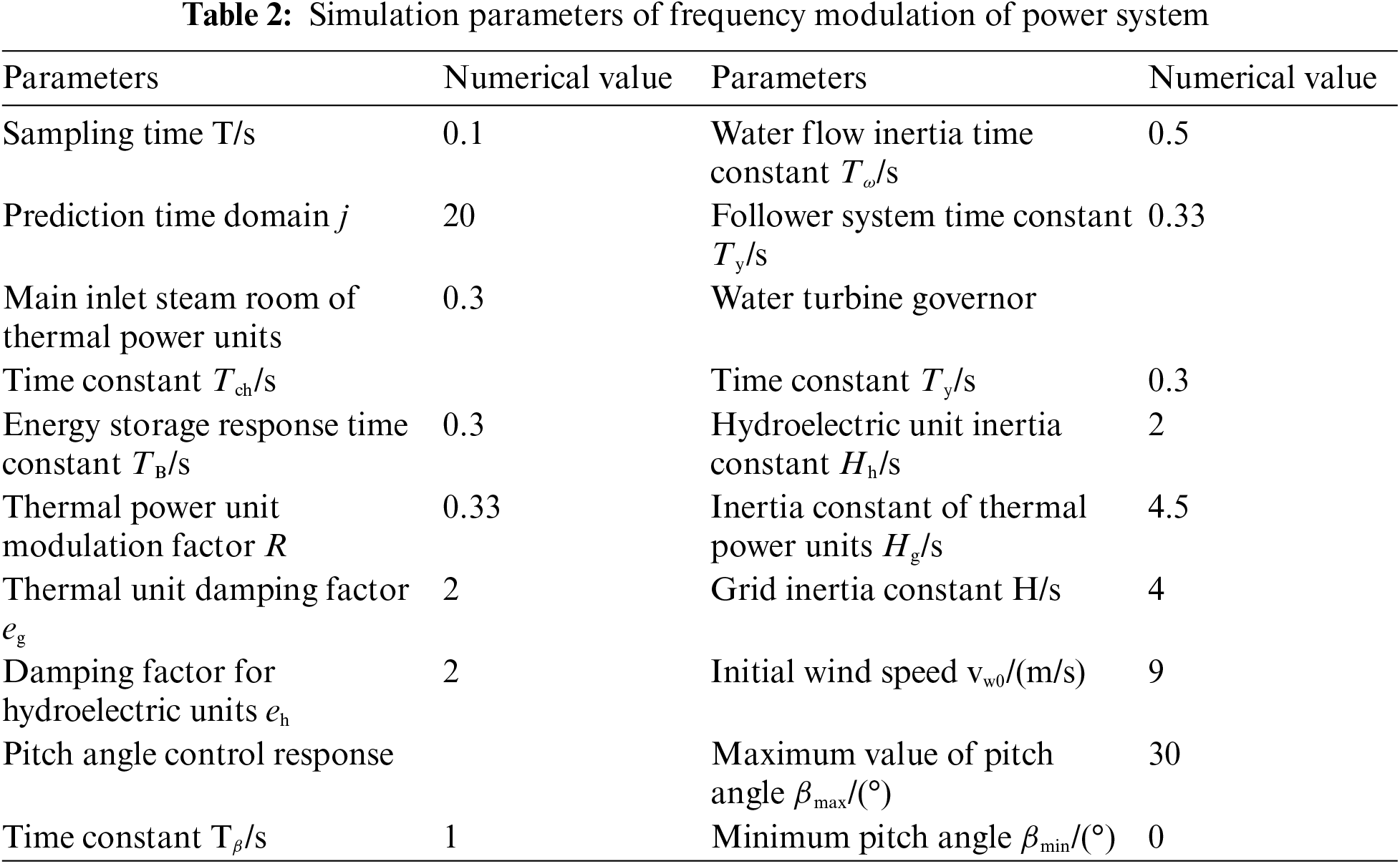
The effectiveness of the proposed control strategy is verified by building a system prediction model in the MATLAB/Simulink simulation platform. The system consists of a thermal power unit, a DFPSU, a hydropower unit with rated capacities of 300, 300, and 200 MW, respectively, a wind power unit consisting of 10 sets of 15 MW wind turbine generators, a lithium battery storage device configured with a capacity of 15 MW/20 MWh, and a photovoltaic power plant with an installed capacity of 150 MW. In this paper, we will construct three different control experiment scenarios aiming to test the practical effectiveness of the proposed control strategy. Specific scenario settings and parameter configurations are detailed in Tables 1 and 2.
For the change of frequency response characteristics of load step disturbance, the system FM indicators are used to measure the frequency fluctuation, which includes the absolute value of the maximum frequency deviation of the system Δfmax, the maximum peak-to-valley difference of the frequency deviation of the system Δfpv.max; the absolute value of the maximum frequency deviation rate of change Δdf/dtmax; the peak-to-valley difference of the frequency deviation rate of change Δdf/dtpv.max.
5.2 System Frequency Response Analysis
The load step fluctuation is shown in Fig. 3, and to simulate the load step occurring in the actual situation, the step is set to occur once every 30 s. This paper sets up the above four scenarios for simulation and analysis, as well as the active output of each unit involved in FM. The results are shown in Fig. 4.
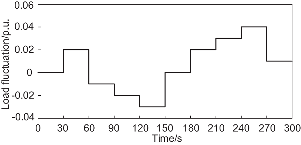
Figure 3: Fluctuations in system load
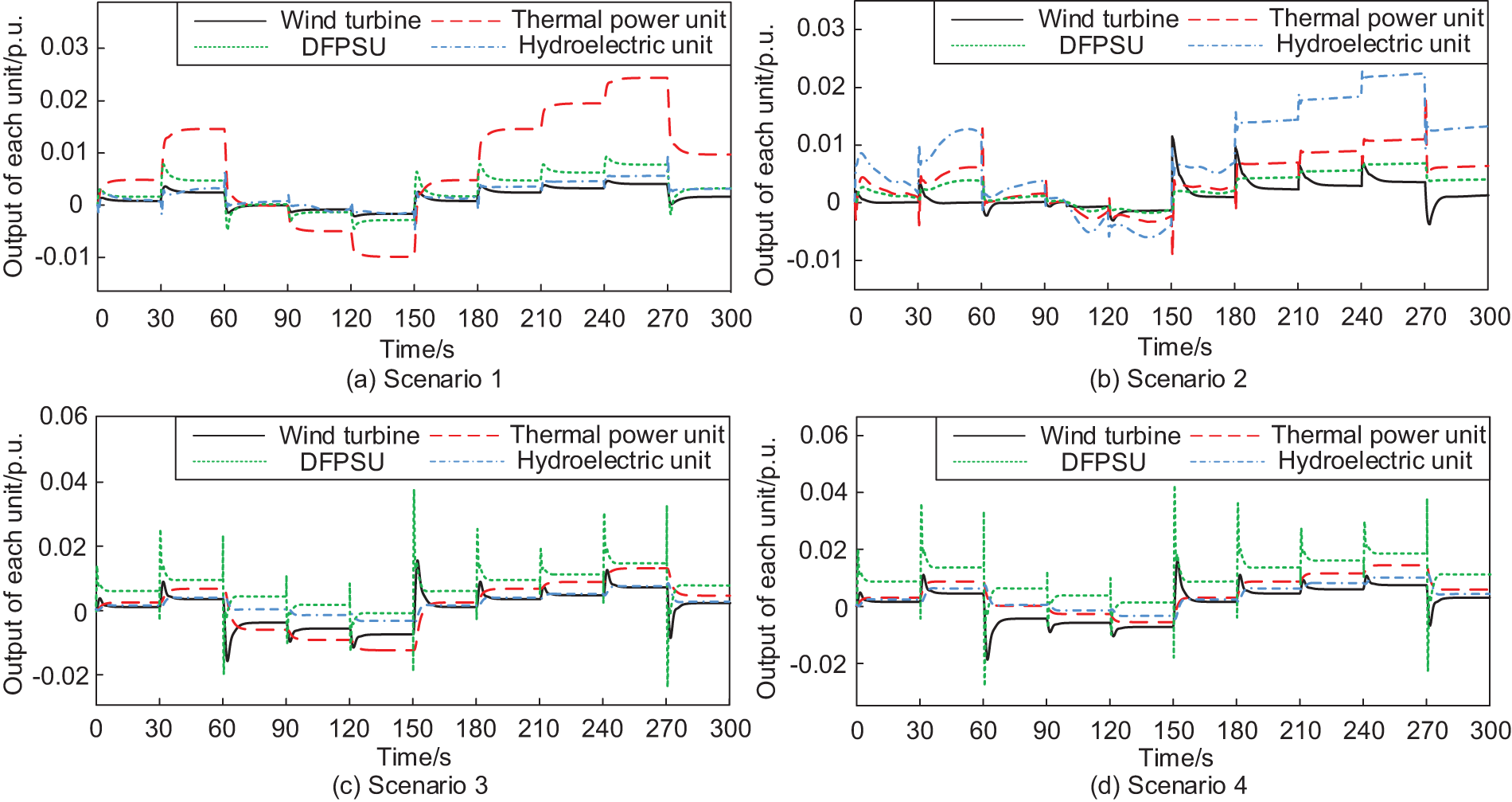
Figure 4: Output change of each unit in four scenarios
From Fig. 4a–d, it can be seen that in Scenario 1, under the action of the proportional-integral (PI) controller, the thermal power unit has the most enormous output, and the output fluctuations of the hydroelectric power unit, DFPSU and wind power unit are more minor; in Scenario 2, under the action of the proportional-integral-differential (PID) controller, the hydroelectric power unit and thermal power unit are used as the main force of frequency regulation, and the output fluctuations of the wind power unit and DFPSU are more minor, with the system frequency response capability being weaker; in Scenario 3, DFPSUs take on more frequency regulation tasks, and the power fluctuation is the largest; in Scenario 4, due to the joint effect of MPC controller and proportional-derivative link, DFPSUs take on more frequency regulation tasks, and wind turbines and hydroelectric generating units participate in the process of regulating the system frequency in concert, effectively reducing the active power burden on thermal generating units, which is the traditional frequency regulation unit, has a slight change amplitude, and the frequency regulation potential of the new energy units is further explored. The frequency regulation potential of new energy units is further explored. Compared to Scenario 3, in Scenario 4, the depth of involvement of thermal units in system FM is reduced, accelerating the system to reach steady state deviation.
Fig. 5 shows the Li-ion battery storage device’s output power and SOC fluctuation in Scenario 4. It can be seen that in the time from 150 to 300 s, with the increase of the output power of the energy storage device, the SOC continues to decrease. However, it is still within the range of SOC constraints, which avoids excessive discharging and effectively ensures the service life of the energy storage device. As seen from Fig. 6, in the case of a step disturbance in the load within 300 s, the primary FM effect of MPC control is better than that of PI and PID control. Among them, the advantage of MPC control is more evident during the periods of 30–60 s and 180–270 s, which is because, under the joint effect of MPC control and proportional-differential control link, the DFPSU releases more FM energy, profoundly participates in the system FM, gives full play to its FM potential, and obtains a better frequency deviation suppression effect.
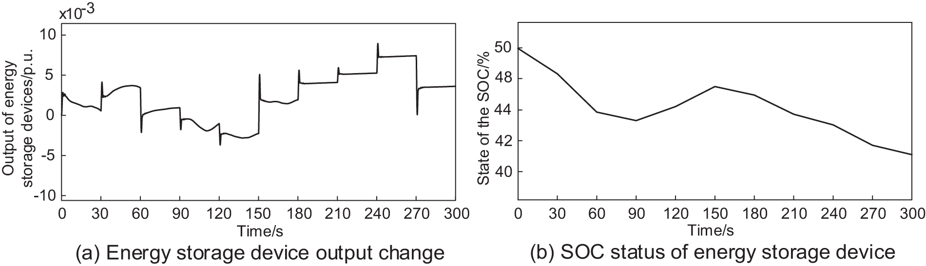
Figure 5: Change in energy storage device output and SOC in Scenario 4
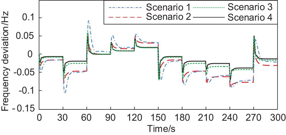
Figure 6: System frequency deviation in four scenarios
The system perturbations are set as output fluctuation of the PV plant and random fluctuation of the load to verify the effectiveness of the proposed control strategy for suppressing the rate of change of frequency deviation, as shown in Figs. 7 and 8. The results of the four cases are shown in Figs. 9 and 10.
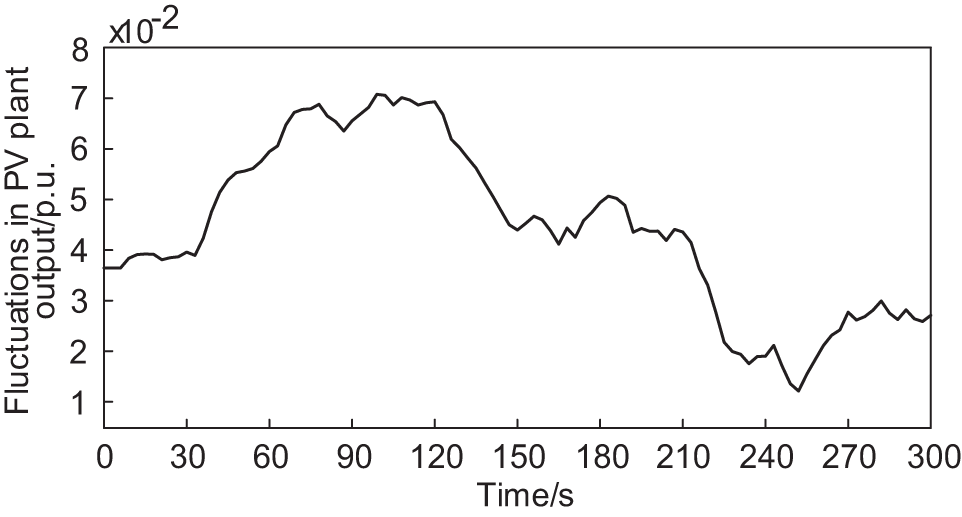
Figure 7: Fluctuations in the output of PV power plants under low light intensity
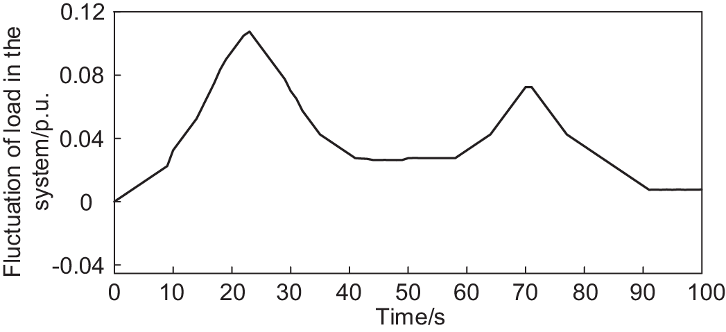
Figure 8: Fluctuations in system load
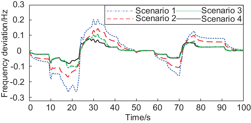
Figure 9: System frequency deviation in four scenarios
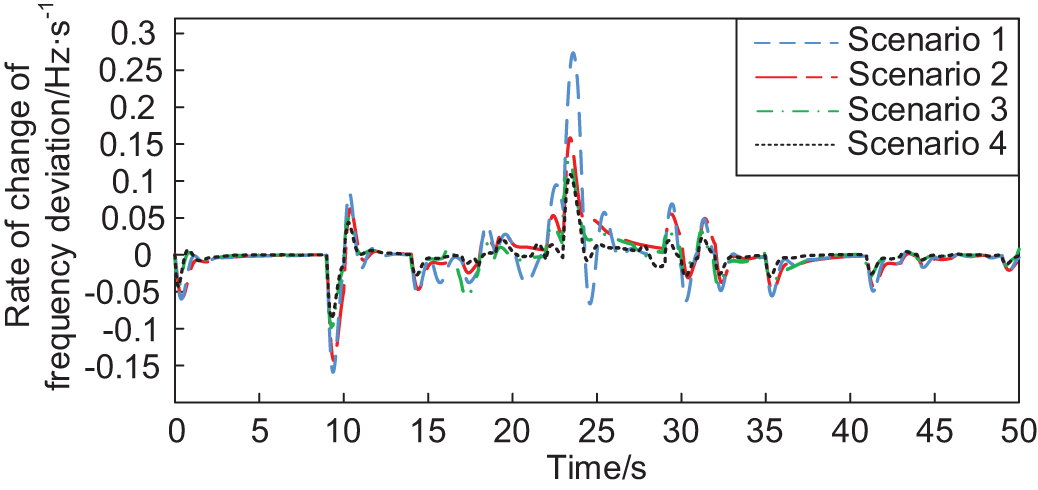
Figure 10: System frequency deviation rate of change
From Fig. 9, it can be seen that under certain light intensity and load perturbation, the one-time FM effect of scene 4 is better than the other three scenes throughout the FM process. Comparison of the curves of Scenario 3 and Scenario 4 shows that the FM curve of Scenario 4 is better than that of Scenario 3 during the period 18–40 s, which is because the proportional-differential control link plays a left and right role in the FM process, increasing the FM depth of the doubly-fed pumped storage unit. Fig. 10 shows that Δdf/dtmax and Δdf/dtpv.max are significantly suppressed by incorporating the proportional-differential control link, and the degree of frequency fluctuation is slowed down. Table 3 compares the system frequency tuning indexes in the four scenarios.
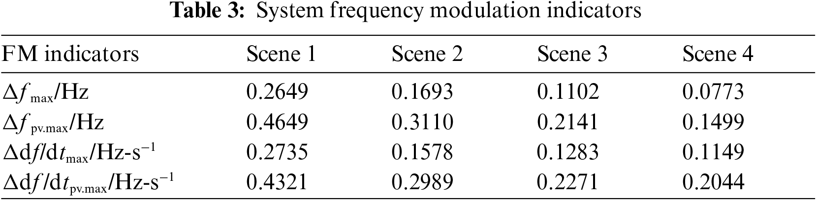
As can be seen from Table 3, Scenario 4 has the smallest values of the four system FM indicators. Compared with the PI and PID control used in Scenarios 1 and 2, the MPC control used in Scenario 4 reduces Δfmax and Δfpv.max by 0.1876, 0.092, and 0.315 and 0.1611 Hz, respectively. Compared with Scenario 3, after adding the control link, Δfmax and Δfpv.max are reduced by 29.9% and 30.0%, respectively. Regarding suppressing the rapid fluctuation of the system frequency, Δdf/dtmax and Δdf/dtpv.max in Scenario 4 are reduced by 58.0%, 27.2% and 52.7%, 31.6%, respectively, compared with Scenario 1 and 2. Meanwhile, compared with Scenario 3, Δdf/dtmax and Δdf/dtpv.max of Scenario 4 were reduced by 10.4% and 10.0%, respectively, with the control link. Therefore, the MPC control strategy with the proportional-differential control link can improve the suppression of system frequency variation by the DFPSU.
Considering the substantial uncertainty of wind speed in a short time, it is unsuitable to participate in system FM when the wind turbine output fluctuates violently, regarded as output disturbance. Setting the wind speed in high, medium, and low three cases of the wind turbine generator (WTG) output disturbance, the system frequency deviation is shown from Figs. 11–13, respectively.
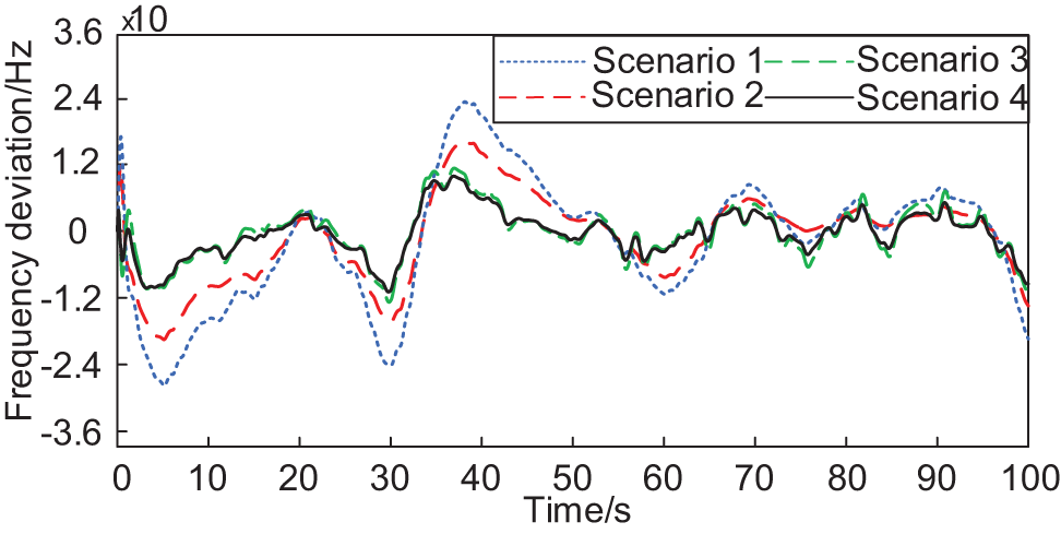
Figure 11: System frequency deviation at low wind speed
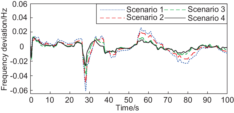
Figure 12: System frequency deviation at medium wind speed
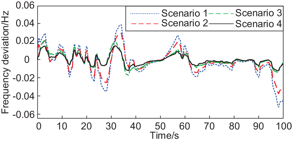
Figure 13: System frequency deviation at high wind speed
From Figs. 11–13, it can be seen that the system frequency fluctuation increases with the increase in wind speed, and the frequency fluctuation of Scene 4 is minimized in all four scenarios for the disturbance of WTG output under different wind speeds. At low wind speeds, the difference between the frequency regulation effects of Scenario 3 and Scenario 4 is slight, and when the uncertainty of wind speed increases, under the action of the proportional-differential control link, the stability of the frequency response under Scenario 4 is more substantial compared to Scenario 3.
The above experimental results confirm that the MPC strategy incorporating the proportional-differential control link suppresses the system frequency deviation and its dynamic rate of change significantly, fully activates the control potential of DFPSUs in the field of system frequency regulation, promotes the further consumption of new energy units, and effectively inhibits the rapid fluctuation of frequency deviation in the new energy power system.
This paper proposes a new energy power system FM control strategy based on MPC to address the system frequency fluctuation problem, and the main conclusions are as follows:
(1) Based on the MPC theory, this paper establishes state-space equations for the units involved in FM within the system according to the operating characteristics of each unit to accurately describe the system’s dynamic behavior.
(2) Considering the rate of change of system frequency deviation, it is proposed to add a proportional-derivative control link to the DFPSU for parameter adjustment to release its FM potential, suppress the rapid fluctuation of system frequency deviation, and establish a system FM index to measure its FM effect.
(3) By comparing with the traditional PI and PID, the results show that the strategy proposed in this paper can optimize the active output of the units in the system, significantly reduce the frequency deviation of the system and its rate of change so that the frequency regulation indexes can reach the optimum, further enhance the capacity of the new energy units to consume, and Improve the system frequency stability.
Acknowledgement: Thanks are due to Muchen Liu for assistance with the experiments and to Ming Guan for valuable discussion.
Funding Statement: This work is supported by the National Natural Science Foundation of China (Project No. 52377082) and the Scientific Research Program of Jilin Provincial Department of Education (Project No. JJKH20230123KJ).
Author Contributions: The authors confirm contribution to the paper as follows: study conception and design: Yuanxiang Luo and Linshu Cai; analysis and interpretation of results: Linshu Cai and Nan Zhang; draft manuscript preparation: Linshu Cai. All authors reviewed the results and approved the final version of the manuscript.
Availability of Data and Materials: Data supporting this study are included within the article.
Ethics Approval: Not applicable.
Conflicts of Interest: The authors declare no conflicts of interest to report regarding the present study.
References
1. J. Fan et al., “Review of black start on new power system based on energy storage technology,” Energy Eng., vol. 120, no. 12, pp. 2857–2878, Nov. 2023. doi: 10.32604/ee.2023.029740. [Google Scholar] [CrossRef]
2. M. N. H. Shazon, A. Jawad, and A. Jawad, “Frequency control challenges and potential countermeasures in future low-inertia power systems: A review,” Energy Rep., vol. 8, no. 4, pp. 6191–6219, Nov. 2022. doi: 10.1016/j.egyr.2022.04.063. [Google Scholar] [CrossRef]
3. P. Makolo, R. Zamora, and T. T. Lie, “The role of inertia for grid flexibility under high penetration of variable renewables—A review of challenges and solutions,” Renew Sustain. Energy Rev., vol. 147, no. 5, Sep. 2021, Art. no. 111223. doi: 10.1016/j.rser.2021.111223. [Google Scholar] [CrossRef]
4. S. A. Mansouri, E. Nematbakhsh, A. Ramos, J. P. Chaves Ávila, J. García-González and S. A. Mansouri, “Bi-level mechanism for decentralized coordination of internet data centers and energy communities in local congestion management markets,” presented at the 2023 IEEE Int. Conf. Energy Technol. Future Grids (ETFGWollongong, Australia, Dec. 3–6, 2023. [Google Scholar]
5. A E M Operator, “Integrated Final Report SA Black System 28 September 2016,” Black System South Australia 28 September 2016–Final Report. Australian Energy Market Operator Limited, 2017. Accessed: Jul. 12, 2024. [Online]. Available: http://www.aemo.com.au/-/media/Files/Electricity/NEM/Market_Notices_and_Events/Power_System_Incident_Reports/2017/Integrated-Final-Report-SA-Black-System-28-September-2016.pdf. [Google Scholar]
6. National Grid ESO, Technical Report on the Events of 9 August 2019, 2020. Accessed: Sep. 6, 2019. [Online]. Available: https://www.nationalgrideso.com/document/152346/download [Google Scholar]
7. ENTSO-E, System Separation in the Continental Europe Synchronous Area on 8 January 2021–Interim Report. Geneva: ENTSO-E, 2021. Accessed: Feb. 26, 2021. [Online]. Available: https://www.entsoe.eu/news/2021/02/26/system-separation-in-the-continental-europe-synchronous-area-on-8-january-2021-interim-report/ [Google Scholar]
8. B. Wang, H. Sun, W. Li, J. Yan, Z. Yu and C. Yang, “Minimum inertia estimation of power system considering dynamic frequency constraints,” Proc. CSEE, vol. 42, no. 1, pp. 114–127, Sep. 2022. doi: 10.13334/j.0258-8013.pcsee.210751. [Google Scholar] [CrossRef]
9. X. Chen, Y. Jiang, V. Terzija, and C. Lu, “Review on measurement-based frequency dynamics monitoring and analyzing in renewable energy dominated power systems,” Int. J. Electr. Power Energy Syst., vol. 155, no. 8, Jan. 2024, Art. no. 109520. doi: 10.1016/j.ijepes.2023.109520. [Google Scholar] [CrossRef]
10. A. Rouhanian, H. Aliamooei-Lakeh, S. Aliamooei-Lakeh, and M. Toulabi, “Improved load frequency control in power systems with high penetration of wind farms using robust fuzzy controller,” Elect. Power Syst. Res., vol. 224, no. 1, Nov. 2023, Art. no. 109511. doi: 10.1016/j.epsr.2023.109511. [Google Scholar] [CrossRef]
11. X. Xiao and Z. Zheng, “New power systems dominated by renewable energy towards the goal of emission peak & carbon neutrality: Contribution, key techniques, and challenges,” Adv. Eng. Sci., vol. 54, no. 1, pp. 47–59, Jan. 2022. doi: 10.15961/j.jsuese.202100656. [Google Scholar] [CrossRef]
12. K. Bruninx, Y. Dvorkin, E. Delarue, H. Pandzic, W. Dhaeseleer and D. S. Kirschen, “Coupling pumped hydro energy storage with unit commitment,” IEEE Trans. Sustain. Energy, vol. 7, no. 2, pp. 786–796, Apr. 2016. doi: 10.1109/TSTE.2015.2498555. [Google Scholar] [CrossRef]
13. J. Zhou, N. Zhang, C. Li, Y. Zhang, and X. Lai, “An adaptive takagi-sugeno fuzzy model-based generalized predictive controller for pumped-storage unit,” IEEE Access, vol. 7, pp. 103538–103555, 2019. doi: 10.1109/ACCESS.2019.2931575. [Google Scholar] [CrossRef]
14. B. Huang, Y. Chen, and R. Baldick, “A configuration based pumped storage hydro model in the MISO day-ahead market,” IEEE Trans. Power Syst., vol. 37, no. 1, pp. 132–141, Jan. 2022. doi: 10.1109/TPWRS.2021.3097270. [Google Scholar] [CrossRef]
15. A. G. Papakonstantinou, A. I. Konstanteas, and S. A. Papathanassiou, “Solutions to enhance frequency regulation in an island system with pumped-hydro storage under 100% renewable energy penetration,” IEEE Access, vol. 11, pp. 76675–76690, 2023. doi: 10.1109/ACCESS.2023.3296890. [Google Scholar] [CrossRef]
16. Z. Zhu, W. Pan, T. Liu, Y. Li, and M. Liu, “Dynamic modeling and eigen analysis of adjustable-speed pumped storage unit in pumping mode under power regulation,” IEEE Access, vol. 9, pp. 155035–155047, 2021. doi: 10.1109/ACCESS.2021.3128627. [Google Scholar] [CrossRef]
17. Y. Chen, W. Xu, Y. Liu, Z. Bao, Z. Mao and E. M. Rashad, “Modeling and transient response analysis of doubly-fed variable speed pumped storage unit in pumping mode,” IEEE Trans. Ind. Electron., vol. 70, no. 10, pp. 9935–9947, Oct. 2023. doi: 10.1109/TIE.2022.3224154. [Google Scholar] [CrossRef]
18. L. Shi, W. Lao, F. Wu, T. Zheng, and K. Y. Lee, “Frequency regulation control and parameter optimization of doubly-fed induction machine pumped storage hydro unit,” IEEE Access, vol. 10, no. 3, pp. 102586–102598, 2022. doi: 10.1109/ACCESS.2022.3208960. [Google Scholar] [CrossRef]
19. Z. Xu, C. Deng, and Q. Yang, “Flexibility of variable-speed pumped-storage unit during primary frequency control and corresponding assessment method,” J. Electr. Power Energy Syst., vol. 145, no. 3, Feb. 2023, Art. no. 108691. doi: 10.1016/j.ijepes.2022.108691. [Google Scholar] [CrossRef]
20. S. Cui, S. Lyu, Y. Ma, and K. Wang, “Improved informer PV power short-term prediction model based on weather typing and AHA-VMD-MPE,” Energy, vol. 307, no. 7, Oct. 2024, Art. no. 132766. doi: 10.1016/j.energy.2024.132766. [Google Scholar] [CrossRef]
21. L. Yang, T. Liu, and D. J. Hill, “Distributed MPC-based frequency control for multi-area power systems with energy storage,” Elect. Power Syst. Res., vol. 190, no. 4, Jan. 2021, Art. no. 106642. doi: 10.1016/j.epsr.2020.106642. [Google Scholar] [CrossRef]
22. C. Wen, Y. Wei, P. Wang, J. Li, J. Zhou and Q. Li, “Modular system of cascaded converters based on model predictive control,” Energy Eng., vol. 121, no. 11, pp. 3241–3261, Oct. 2024. doi: 10.32604/ee.2024.051810. [Google Scholar] [CrossRef]
23. S. V. Raković and W. S. Levine, “The essentials of MPC,” in The Handbook of MPC. Berlin, Germany: Springer, 2019, pp. 4–15. [Google Scholar]
24. Z. Tang, J. Liu, and K. Liu, “Two-stage coordinated frequency regulation control model for thermal power and energy storage based on stochastic MPC,” Automat. Electr. Power Syst., vol. 47, no. 3, pp. 86–95, Feb. 2023. [Google Scholar]
25. B. Kim and E. H. Abed, “Power system fast frequency control in low inertia environment using MPC,” presented at the 2024 IEEE Green Technol. Conf. (GreenTechSpringdale, AR, USA, Apr. 3–5, 2024. [Google Scholar]
26. M. Wang, B. Gao, Y. Jiang, Y. Tian, W. Dong and X. Shi, “MPC based active frequency support strategy for combined wind/photovoltaic/storage power station,” presented at the 2023 IEEE 6th Int. Electr. Energy Conf. (CIEECHefei, China, May 12–14, 2023. [Google Scholar]
27. Z. Xu, C. Deng, and Q. Yang, “A primary frequency control strategy for variable-speed pumped-storage plant in generating mode based on adaptive MPC,” Elect. Power Syst. Res., vol. 221, no. 3, Aug. 2023, Art. no. 109356. doi: 10.1016/j.epsr.2023.109356. [Google Scholar] [CrossRef]
Cite This Article
 Copyright © 2025 The Author(s). Published by Tech Science Press.
This work is licensed under a Creative Commons Attribution 4.0 International License , which permits unrestricted use, distribution, and reproduction in any medium, provided the original work is properly cited.
 Downloads
 Citation Tools