
 Submit a Paper
 Propose a Special lssue
 Open Access
ARTICLE

Design of Voltage Equalization Circuit and Control Method for Lithium-ion Battery Packs
1 School of Electrical and Information Engineering, Jiangsu University of Technology, Changzhou, 213001, China
2 Research and Development Department, Shuangdeng Group Co., Ltd., Taizhou, 225500, China
3 School of Automotive and Traffic Engineering, Jiangsu University, Zhenjiang, 212013, China
* Corresponding Author: Lantian Ge. Email:
(This article belongs to the Special Issue: Advanced Modelling, Operation, Management and Diagnosis of Lithium Batteries)
Energy Engineering 2025, 122(2), 733-746. https://doi.org/10.32604/ee.2024.059453
Received 08 October 2024; Accepted 15 November 2024; Issue published 31 January 2025
 View Full Text
 Download PDF
Abstract
The active equalization of lithium-ion batteries involves transferring energy from high-voltage cells to low-voltage cells, ensuring consistent voltage levels across the battery pack and maintaining safety. This paper presents a voltage balancing circuit and control method. First, a single capacitor method is used to design the circuit topology for energy transfer. Next, real-time voltage detection and control are employed to balance energy between cells. Finally, simulation and experimental results demonstrate the effectiveness of the proposed method, achieving balanced voltages of 3.97 V from initial voltages of 4.10, 3.97, and 3.90 V. The proposed circuit is simple, reliable, and effectively prevents overcharge and overdischarge.Keywords
Nomenclature
| BMS | Battery Management System |
| DC | Direct Current |
| UAVs | Unmanned Aerial Vehicles |
| MOS | MOSFET |
| PWM | Pulse Width Modulation |
| MCU | Microcontroller Unit |
In recent years, the growing severity of global environmental challenges has led to a significant reduction in non-renewable energy reserves, such as coal and oil. As a result, the demand for renewable energy has surged, and lithium-ion batteries are increasingly used in electric vehicles. Voltage imbalance among battery cells can result in overcharge or overdischarge, potentially causing fires or explosions, highlighting the need for improved voltage balancing technology [1]. Lithium-ion batteries are favored by electric vehicle manufacturers due to their high energy density, fast response time, low maintenance costs, and convenience [2]. However, their individual voltages are relatively low, multiple cells must be connected in series to achieve the high voltage needed for electric vehicles, typically exceeding 400 V, which can lead to performance inconsistencies and potential voltage imbalances over time [3–5].
In order to maximize the capacity utilization of the battery pack composed of multiple single batteries, and to prolong the service life of the batteries and while ensuring that the battery pack works in the best operating condition, the battery equalization technology is adopted [6], that is, the energy of each single battery is equalized in the working process of the battery pack to reduce the voltage difference between the batteries so that the voltage of all single batteries can be consistent [7]. This addresses the issue of voltage imbalance, thereby improving the capacity and service life of the entire battery pack. In addition, prolonging the service life of batteries helps to reduce the number of waste batteries, which significantly contributes to environmental protection. The earliest and most widely used equalization circuit is the energy dissipation equalization circuit [8]. By controlling the circuit connecting the high-voltage battery and the resistor, the excess energy of the high-voltage battery is converted into thermal energy and dissipated [9,10], which ensures that the voltage of all batteries tends to be consistent [11]. The main disadvantages include significant energy loss, low utilization efficiency, and increased thermal effects in the battery pack. The active equalization method based on inductance uses inductance as the carrier of energy transfer to realize energy transfer [12]. However, when the number of batteries increases, the circuit becomes more and more complex, and the control method is also more complicated. There is also a balanced topology based on the transformer [13], which uses the transformer as energy. The energy storage and transmission components realize the mutual conversion of electric energy and magnetic energy through the mutual inductance of the transformer, so as to carry out energy transfer. With the increase in the number of series batteries, the winding of the transformer coil increases the complexity of the circuit and the cost of the circuit. In addition, the leakage inductance problem may have a certain impact on the system performance. The equalization topology based on the converter uses DC/DC to convert electricity [14]. However, when the number of equalization units increases, the cost of components and the difficulty of control will greatly increase, and the equalization speed and efficiency will also be affected. It can only transfer energy between adjacent battery cells, and its practicability is limited. Through active voltage equalization, this method allows for real-time monitoring and adjustment during operation, ensuring battery stability. Therefore, various voltage-sharing circuits have found extensive application in electric vehicles, energy storage systems [15], robots and unmanned aerial vehicles (UAVs). At the same time, the battery management system (BMS) requires more efficient and intelligent voltage grading technology to adapt to diverse application scenarios and complex working conditions. As a key component of BMS, the voltage grading circuit needs to be continuously improved to meet the requirements of higher performance, lower cost and higher reliability. Therefore, it is necessary to design an efficient and simple equalization circuit. This paper proposes a simple yet effective equalization circuit design and control method to address the complexity of existing solutions. The feasibility of the proposed method has been validated through both simulations and physical experiments, demonstrating its practical applicability in reducing control complexity.
The objective of this paper is to design an equalization circuit and control method capable of actively balancing lithium-ion battery packs, thereby preventing overcharge and over-discharge. The structure of this paper is arranged as follows: First, the topological working principle of an active balancing circuit using capacitors as energy storage components is introduced; Secondly, the design of a voltage comparison balancing control strategy is discussed; Then, the rationality of the circuit and control method is verified through simulation; Finally, the feasibility of the circuit is verified through physical experiments.
2 Design of Equalization Circuit and Control Method
2.1 Voltage Sharing Principle of the Circuit
In this paper, the single capacitor method is employed to achieve the energy balance between lithium-ion batteries. By controlling the on-off of the switch, the single battery with higher voltage in the battery pack is charged to the capacitor C, and then the capacitor C charges the battery with lower voltage. The energy transfer between the single battery with the highest voltage and the lowest voltage in the whole battery pack is realized through the capacitor C. Thereby realizing the voltage equalization of different batteries among the battery packs within a certain period of time. The equalization circuit topology is displayed in Fig. 1.

Figure 1: Voltage balancing circuit topology of lithium-ion battery pack with single capacitor method
Taking the balancing circuit of two batteries as an example, it is assumed that the voltage of BT1 is higher and the voltage of BT3 is lower. The turn-on and turn-off processes of control switches S11, S12, S31 and S32 are shown in Figs. 2 and 3.

Figure 2: S11 and S12 turn-on and turn-off process

Figure 3: S11 and S12 turn-on and turn-off process
In a period of 0 to t1, S11 and S12 are turned on, that is, the BT1 is directly connected in parallel with the capacitor C, energy is transferred from the BT1 to the capacitor C, the capacitor C is rapidly charged from the initial zero state, rising quickly until it matches the voltage of BT1, after the voltage reaches a balanced state, the capacitance C is turned off, and at this time the capacitance C has stored corresponding energy prepare for the next step of charging BT2, as shown in Fig. 4.

Figure 4: Schematic diagram of current flow direction during 0 to t1
During the time from t1 to t2, S11 and S12 are turned off, and S31 and S32 are turned on. At this time, the voltage of the capacitor C should be the same as the voltage at both ends of BT1 and greater than the voltage at both ends of BT3, so that the current flows from C to BT3, and the energy from BT1 stored in C is gradually released to BT3, as shown in Fig. 5.

Figure 5: Schematic diagram of current flow direction during t1 to t2
The period from 0 to t2 is taken as a period, and the switch is controlled to be alternately turned on and turned off in one period, so that the effect of balancing the voltages of the BT1 and the BT2 can be achieved. The voltage equalization circuit of the multi-cell battery follows the same control principle described above, but the difference is that the voltage equalization is conducted between the highest voltage battery and the lowest voltage battery within the multi-cell system. Therefore, when designing the control method, it is necessary to identify the highest and the lowest voltage prior to equalization to facilitate energy transfer and equalization until the process is completed.
When BT1 discharges the capacitor C in the time of 0 to t1, the equivalent circuit is shown in Fig. 6.

Figure 6: Equivalent circuit from 0 to t1
It is assumed that the internal resistances of all batteries are equal, R is the sum of the internal resistance of battery BT1 and the internal resistance of capacitor C, the initial voltage of capacitor C is 0, the voltage at both ends of BT1 is U0, the voltage at both ends of C is uc. When S11 and S12 are closed, the circuit is a first-order dynamic circuit in the zero state, and according to KVL, the differential equation of the circuit is
The differential equation of Formula (1) has a solution of
The time constant τ = RC in the Formula (2) indicates that the capacitor voltage rises to 0.632U0 after a time constant τ, so when designing the control method and circuit, the turn-on time of switches S11 and S12 should be at least greater than τ.
Similarly, when BT3 is charged by capacitor C during t1 to t2, the equivalent circuit is shown in Fig. 7.

Figure 7: Equivalent circuit from t1 to t2
In Fig. 7, R is the sum of the internal resistance of the battery BT3 and the internal resistance of the capacitor C, and the initial voltage of the capacitor C is Uc. Suppose that the voltage at both ends of BT3 is U1, and the voltage at both ends of C is uc. When S31 and S32 are closed, ignoring the process of charging the capacitor from the battery, the circuit can be approximated as a first-order dynamic circuit with zero input, and the differential equation of the circuit is
Considering that the voltage at both ends of BT3 is U1 and the initial voltage at both ends of the equivalent capacitor is (Uc−U1), the solution of the differential equation of Formula (3) is
Similar to the case of 0~t1, the time constant τ = RC in the Formula (4), after a time constant τ, the capacitor voltage attenuates to 0.368(Uc−U1), so when designing the control method, the turn-on time of switches S31 and S32 should also be at least greater than τ.
2.2 Design of Circuit Control Method
Based on the above analysis, this section uses a voltage balancing circuit with three batteries as an example to design a control method based on the voltage comparison approach. The control method allows energy to flow from a battery with a higher voltage to one with a lower voltage through a capacitor, achieved by comparing the battery voltages and alternately switching the paths connected to the capacitor and batteries.
The control method works as follows: Let V1, V2, and V3 represent the voltages across BT1, BT2, and BT3, respectively. When V1 > V3 > V2, where V1 has the highest voltage, V2 has the lowest, and V3 is intermediate, S11 and S12 are alternately activated with S21 and S22, enabling energy transfer from BT1 to BT2 via capacitor C. During this process, S31 and S32 are turned off, disconnecting BT3 from the circuit to prevent interference with the energy flow between BT1 and BT2.
After several cycles, the energy is continuously output from the battery with the maximum voltage to the battery with the minimum voltage through the capacitor C. When V1 = V2 = V3, S11, S12, S21, S22 and S31, S32 are all turned off, and the equalization is completed. The flow chart is shown in Fig. 8.
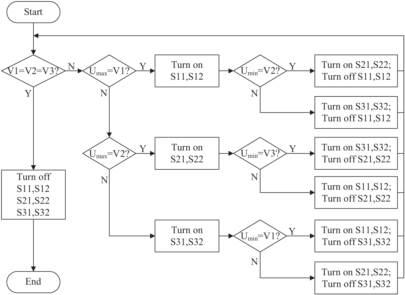
Figure 8: Flow chart of control method for voltage equalizing circuit of three batteries
3.1 Construction of Simulation Circuit
Simulink software is employed to develop the voltage equalization circuit and control method model of three lithium-ion batteries as depicted in Fig. 1. In metal oxide semiconductor (MOS), a parasitic diode exists between the source and drain, which can conduct in the reverse direction. This characteristic affects current control, especially during reverse current flow, even when no control signal is applied. In [16], this paper adopts a solution that connects two MOSs in an anti-series configuration, which involves swapping the source and drain terminals of the MOSs. This configuration effectively blocks the diode path of the MOSs. The flow of the current can be completely controlled in the conduction state, and an ideal power electronic switch effect is realized. The component parameters of the circuit topology are detailed in Table 1.

The control method of the equalization circuit for three lithium-ion batteries is the same as the analysis in Section 2.2 of this paper. Here, only the case of V1 > V2 > V3 is taken as an example. In Simulink, by adjusting the state of charge (state of charge, SOC) of the lithium-ion battery module, the lithium-ion batteries with the same specifications can have different voltages. In this simulation, the voltage of the lithium-ion battery BT1 is set to 4.10 V, and the voltage of BT2 is set to 3.97 V, the voltage of BT3 is 3.90 V.
3.2 Simulation Results of Lithium-ion Battery Voltage Equalization Circuit
Among the three lithium-ion batteries, the battery with the maximum voltage is BT1, and the battery with the minimum voltage is BT3. After the simulation, the conduction waveforms of S11, S12, S21, S22 and S31, S32 control terminals are shown in Fig. 9. It can be seen that V1 is the maximum and V3 is the minimum at the beginning, so S11, S12 and S31, S32 drive the anti-series MOS transistors to conduct alternately, and S21, S22 do not output signals. It is consistent with the control method designed above.

Figure 9: Three-cell equalization simulation input anti-series MOS transistor gate pulse width modulation (PWM) waveform
After simulation, the voltage waveforms of the three batteries are shown in Fig. 10. Initially, energy is transferred from BT1 to BT3 through capacitor C. When V3 exceeds V2, energy is then transferred from BT1 to BT2 through capacitor C. At this point, the voltage difference between V2 and V3 is very small, allowing V2 to exceed V3 in a very short time. Consequently, energy flows from BT1 to BT3 through capacitor C once again, repeating this cycle until the voltage equalization is complete. As seen in Fig. 10, the battery voltages eventually stabilized at 3.98 V after 6 h, successfully achieving voltage balance among the batteries.

Figure 10: Simulation results of voltage equalizing circuit of three batteries voltage waveform
4 Hardware Physical Verification
4.1 Construction of Hardware Experiment Platform
To verify the design of the lithium-ion battery voltage equalization circuit and control method, a voltage equalization circuit with three lithium-ion batteries was constructed as an example. The functional block diagram of the experimental circuit is shown in Fig. 11, and the experimental verification platform is depicted in Fig. 12. Additionally, the oscilloscope used in this physical verification was the Keysight MSOX4104A model.

Figure 11: Functional block diagram of experimental circuit

Figure 12: Overall circuit diagram of experimental verification hardware
The battery used in this experiment is Naijie 10440 lithium-ion battery, with parameters consistent with those in the above simulation, and the capacity is 300 mAh. Small-capacity batteries reach equilibrium faster than large-capacity batteries because they store less energy, allowing them to balance more quickly during the voltage equalization process. This rapid response characteristic is particularly important for the voltage equalization process in experiments and practical applications, which can significantly reduce the equalization time and improve the overall efficiency and response speed of the system.
4.2 Experimental Results of Lithium-ion Battery Voltage Equalization Circuit
At the beginning of the experiment, first verify the accuracy of the measurement value of the physical platform in this paper. Only the accurate voltage value can reflect the real internal state of lithium-ion batteries and achieve better balance. The comparison between the measured value and the actual value of the voltage of the lithium-ion battery cell is shown in Table 2. The error is small and is within the allowable error range.

The output pins of the PWM signals from the microcontroller are connected to the PWM inputs of the three amplification modules. According to the algorithm design, the main program compares the voltages returned by the ADC module to identify the batteries with the maximum, minimum, and intermediate voltages. A positive PWM signal is then output to the battery with the highest voltage, while an inverted PWM signal is applied to the battery with the lowest voltage to drive the MOSFETs. For the battery with the intermediate voltage, no PWM signal is output. The oscilloscope test reveals that the output waveform of the microcontroller unit (MCU) is shown in Fig. 13, which is consistent with the simulation Fig. 9. The positive PWM wave has an amplitude of approximately 3.28 V, the amplitude of the negative PWM wave is 3.35 V, and the turn-on voltage of the MOS transistor IRFZ44N is about 4 V. The direct output PWM wave fails to meet the turn-on voltage requirement of the MOS transistor IRFZ44N used in the experiment, MOSs cannot be controlled by waveforms exported by MCU.

Figure 13: Output PWM waveform of single-chip microcomputer of three-cell voltage equalization circuit
Connect the waveform output by the MCU to the amplification module. The PWM wave output by the out port of the amplification module and the output waveform of the MCU is shown in Fig. 14. Channel 1 is the output waveform of the MCU, with an amplitude of about 3.35 V. Channel 2 is the amplified waveform, with an amplitude of about 8 V and a frequency of 100.02 Hz. The module is a reverse output module, and the output waveform is opposite to the input, but this has no effect on the PWM wave output with a duty cycle of 50% used in the experiment, and the turn-on voltage requirement of the MOS tube IRFZ44N is met.
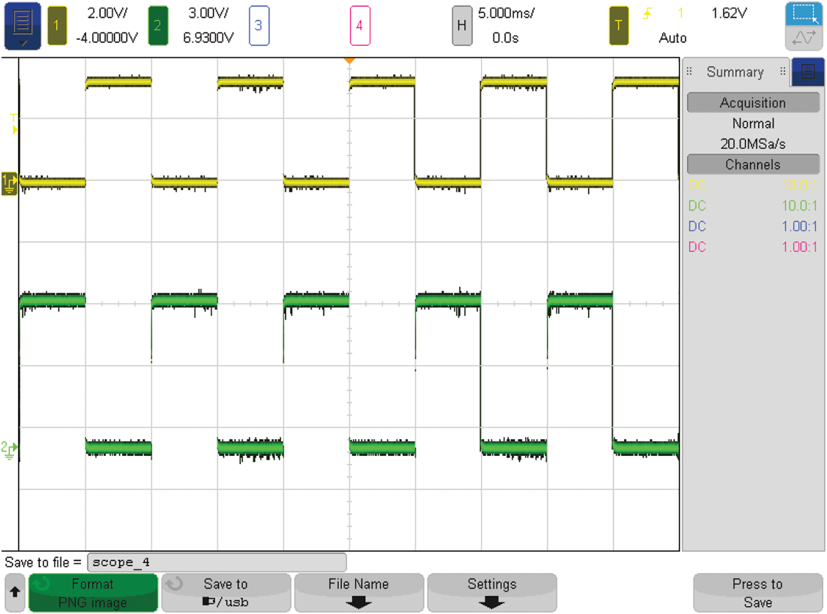
Figure 14: Comparison of waveforms before and after signal amplification module
Finally, amplify the signals S11, S12, S21, S22 and S31, S32, the waveform is as shown in Fig. 15. Channel 1 is a forward PWM wave, and Channel 2 is a reverse PWM wave. The voltage amplitude of both is 8 V, the frequency is 100.02 Hz, and the direction is opposite. Channel 4 continues to be at a low level.

Figure 15: Comparison of output PWM waveform of three-cell equalization circuit amplification module and MCU
To initiate the operation of the entire circuit, connect the output terminals of the three amplification modules to the control module. At time t = 0, the voltage across BT1 is 4.08 V, BT2 is 3.97 V, and BT3 is 3.91 V. After a certain period, the voltages of all three batteries eventually equalize to 3.97 V. The relationship between voltage and time for BT1, BT2, and BT3 is illustrated in Fig. 16. Initially, energy flows from BT1 to BT3 via capacitor C. As the voltages of BT3 and BT2 approach each other, it takes only a brief moment for BT3 to exceed BT2, allowing energy to flow from BT1 to BT2 via capacitor C. Similarly, after a short time, BT2 exceeds BT3, causing energy to flow again from BT1 to BT3. As with the two-cell equalization circuit, the voltage difference is inversely related to the equalization time.

Figure 16: Balancing results of BT1, BT2 and BT3
Compared to the simulation results, the experimental results show that the voltage of the three lithium-ion batteries reaches equilibrium at 3.97 V after 6.14 h. The experimental outcomes are largely consistent with the simulation, with minor discrepancies that may be attributed to the fact that the capacitors, MOSFETs, and other components used in the experiment are not ideal, leading to on-state impedance.
This paper proposes an active voltage equalization circuit and a control strategy to address the unbalanced discharge issue in lithium-ion battery packs. Based on simulation and experimental results, the following conclusions are drawn:
1. The proposed single capacitor equalization circuit has a simple structure, fewer components, and effectively conserves resources.
2. The voltage comparison-based control method effectively balances the cells within the battery pack.
3. The voltage equalization error is less than 0.5%, demonstrating high accuracy.
Future research will focus on improving the voltage equalization rate, achieving better equalization even in cases of minor voltage differences, and addressing heat loss and recovery, which were not considered in this study.
Acknowledgement: We acknowledge Jiangsu University of Technology for providing a stable working environment and express our gratitude to all the authors for their contributions.
Funding Statement: This research was funded by the Basic Science (Natural Science) Research Project of Colleges and Universities in Jiangsu Province, Grant Number 22KJD470002.
Author Contributions: Qi Wang proposed the research direction and conducted the simulation studies. Lantian Ge, Yibo Huang, and Tianru Xie developed the hardware circuit. Yandong Gu and Tao Zhu drafted the manuscript, and Xuehua Gao handled reference formatting. All authors reviewed the results and approved the final version of the manuscript.
Availability of Data and Materials: All data used in this study were obtained through our experiments, with no external datasets involved.
Ethics Approval: Not applicable.
Conflicts of Interest: The authors declare no conflicts of interest to report regarding the present study.
References
1. D. Ouyang, B. Liu, J. Huang, and Z. Wang, “Degradation and safety performance of lithium-ion cells under high-rate charging discharging scenarios,” Process Saf. Environ. Prot., vol. 185, pp. 76–85, Mar. 2024. doi: 10.1016/j.psep.2024.03.064. [Google Scholar] [CrossRef]
2. V. Kabra et al., “Lithium plating characteristics in high areal capacity lithium-ion battery electrodes,” ACS Appl. Mater. Interfac., vol. 16, no. 27, pp. 34830–34839, Jul. 2024. doi: 10.1021/acsami.4c02516. [Google Scholar] [PubMed] [CrossRef]
3. J. Xu and B. Cao, “Battery management system for electric drive vehicles—Modeling, state estimation and balancing,” in New Appl. Electr. Drives, Dec. 2015. doi: 10.5772/61609. [Google Scholar] [CrossRef]
4. W. D. Fang, H. L. Chen, and F. M. Zhou, “Fault diagnosis for cell voltage inconsistency of a battery pack in electric vehicles based on real-world driving data,” Comput. Electr. Eng., vol. 102, Sep. 2022, Art. no. 108095. doi: 10.1016/j.compeleceng.2022.108095. [Google Scholar] [CrossRef]
5. P. Wang, Y. Q. Wei, Q. Peng, C. X. Wen, and J. L. Li, “A new layered bidirectional equalizer based on a novel resonant voltage balance converter for the battery voltage active equalization of energy storage system,” IET Power Electron., vol. 15, pp. 1877–1893, Dec. 2022. doi: 10.1049/pel2.12355. [Google Scholar] [CrossRef]
6. E. Zhang, C. Xu, G. Liu, K. Jiang, and K. Wang, “An active battery equalization scheme for lithium iron phosphate batteries,” Energy Proc., vol. 158, pp. 4702–4707, Feb. 2019. doi: 10.1016/j.egypro.2019.01.733. [Google Scholar] [CrossRef]
7. Y. Hua et al., “A comprehensive review on inconsistency and equalization technology of lithium-ion battery for electric vehicles,” Int. J. Energy Res, vol. 44, no. 14, pp. 11059–11087, Nov. 2020. doi: 10.1002/er.5683. [Google Scholar] [CrossRef]
8. F. Fei, B. Song, J. N. Xu, W. Na, and K. Zhang, “Multiple time scale state-of-charge and capacity-based equalisation strategy for lithium-ion battery pack with passive equaliser,” J. Energy Storage, vol. 53, Sep. 2022, Art. no. 105196. doi: 10.1016/J.EST.2022.105196. [Google Scholar] [CrossRef]
9. I. C. Guran, A. Florescu, and L. A. Perişoară, “SPICE model of a passive battery management system,” IEEE Access, vol. 12, pp. 4000–4014, Jan. 2022. doi: 10.1109/ACCESS.2023.3349186. [Google Scholar] [CrossRef]
10. X. H. Li, X. Yin, Z. B. Tian, X. Y. Jiang, L. Jiang and S. Jeremy, “Multi-layer state of health balancing control for a battery-based energy storage system to extend cycle life based on active equalization circuits,” Front. Energy Res., vol. 10, Sep. 2022, Art. no. 966422. doi: 10.3389/fenrg.2022.966422. [Google Scholar] [CrossRef]
11. W. B. Sun, Y. L. Li, L. Z. Liu, and R. K. Mai, “A switched-capacitor battery equalization method for proving balancing speed,” IET Electric Power Appl., vol. 15, pp. 555–569, Mar. 2021. doi: 10.1049/elp2.12045. [Google Scholar] [CrossRef]
12. A. A. Diazcomas, A. A. Estévez-Bén, J. R. Reséndiz, M. A. M. Prado, R. V. C. Serrano and S. Thenozhi, “A review of battery equalizer circuits for electric vehicle applications,” Energies, vol. 13, no. 21, Oct. 2020, Art. no. 5688. doi: 10.3390/en13215688. [Google Scholar] [CrossRef]
13. C. S. Lu, L. Y. Kang, X. Luo, J. Q. L. Hu, and H. Y. Lin, “A novel lithium battery equalization circuit with any number of inductors,” Energies, vol. 12, no. 24, Dec. 2019, Art. no. 4764. doi: 10.3390/en12244764. [Google Scholar] [CrossRef]
14. L. Tu and M. Xie, “Research on reconfigurable topology layered equalization method based on maximum capacity utilization,” PLoS One, vol. 18, no. 12, Dec. 14, 2023, Art. no. e0295425. doi: 10.1371/journal.pone.0295425. [Google Scholar] [PubMed] [CrossRef]
15. W. B. Liao, Y. R. Chen, J. Zeng, and X. B. Hong, “Analysis and design of composite-structure resonant switched-capacitor voltage equalization topology for series energy storage systems,” J. Power Electron., vol. 22, no. 4, pp. 641–652, Apr. 2022. doi: 10.1007/s43236-021-00378-7. [Google Scholar] [CrossRef]
16. H. A. K. M. Ahasan et al., “Voltage equalization circuit for retired batteries for energy storage applications,” Energy Rep., vol. 8, no. 4, pp. 367–374, Nov. 2022. doi: 10.1016/j.egyr.2022.05.154. [Google Scholar] [CrossRef]
Cite This Article
 Copyright © 2025 The Author(s). Published by Tech Science Press.
This work is licensed under a Creative Commons Attribution 4.0 International License , which permits unrestricted use, distribution, and reproduction in any medium, provided the original work is properly cited.
 Downloads
 Citation Tools