
 Submit a Paper
 Propose a Special lssue
 Open Access
ARTICLE

A Novel Control Strategy Based on -VSG for Inter-Face Converter in Hybrid Microgrid
Department of Electrical Engineering, Jiangsu University, Zhenjiang, 21200, China
* Corresponding Author: Dongyang Yang. Email:
Energy Engineering 2025, 122(2), 471-492. https://doi.org/10.32604/ee.2025.059651
Received 14 October 2024; Accepted 19 December 2024; Issue published 31 January 2025
 View Full Text
 Download PDF
Abstract
The rapid development of new energy power generation technology and the transformation of power electronics in the core equipment of source-grid-load drives the power system towards the “double-high” development pattern of “high proportion of renewable energy” and “high proportion of power electronic equipment”. To enhance the transient performance of AC/DC hybrid microgrid (HMG) in the context of “double-high,” a type virtual synchronous generator (-VSG) control strategy is applied to bidirectional interface converter (BIC) to address the issues of lacking inertia and poor disturbance immunity caused by the high penetration rate of power electronic equipment and new energy. Firstly, the virtual synchronous generator mechanical motion equations and virtual capacitance equations are used to introduce the virtual inertia control equations that consider the transient performance of HMG; based on the equations, the -type equivalent control model of the BIC is established. Next, the inertia power is actively transferred through the BIC according to the load fluctuation to compensate for the system’s inertia deficit. Secondly, the -VSG control utilizes small-signal analysis to investigate how the fundamental parameters affect the overall stability of the HMG and incorporates power step response curves to reveal the relationship between the control’s virtual parameters and transient performance. Finally, the PSCAD/EMTDC simulation results show that the -VSG control effectively improves the immunity of AC frequency and DC voltage in the HMG system under the load fluctuation condition, increases the stability of the HMG system and satisfies the power-sharing control objective between the AC and DC subgrids.Keywords
Glossary/Nomenclature/Abbreviations
| BIC | Bidirectional interface converter |
| G-DCEMF | Generalized DC Electromotive Force |
| HMG | Hybrid microgrid |
| MG | Microgrid |
| PLL | Phase-locked loop |
| SPWM | Sine pulse width modulation |
The power system is establishing the “double high” development trend of “high proportion of renewable energy” and “high proportion of power electronic equipment” as a result of the growth of new energy generation and the evolution of “power electronics” of energy conversion equipment [1]. The use of HMG to address the issue of distributed energy consumption and absorption has grown in popularity to optimize the benefits of distributed power generation. HMG not only reduces the number of energy conversion devices but also has more flexibility than single-system MGs, which can be adapted to the actual needs and is an essential means to improve the utilization of resources in the context of “double-high” [2,3].
Many scholars have made significant contributions to the research of hybrid AC-DC microgrids. For example, literature [4] proposed a planning model to solve the optimal sizing problem of hybrid AC/DC microgrids by a novel GA/AC OPF algorithm, which provides a basis for designing bidirectional interface converters. In addition, research on toughness-driven modelling, operation, and evaluation of hybrid AC/DC microgrids is also of great significance, as it can help to cope better with extreme events and improve the toughness of microgrids [5]. In the HMG system, BIC coordinates the power between MGs, so the study and control of BIC is critical [6,7]. A new active sharing control based on droop control has been proposed to simulate the droop characteristics of a traditional synchronous generator, aiming to realize the power allocation and voltage and frequency regulation functions of the MG [8]. A normalized bidirectional droop control approach was presented for the power-sharing problem in HMGs. This method calculates the transmitted power flow by comparing the two normalized values [9,10]. A hierarchical control strategy for BICs is presented in the literature [11]. This strategy may maximize power interchange between the distribution grid and the MG while limiting the voltage variation brought on by droop control to a particular degree. However, the traditional droop control strategy can no longer actively provide inertia support for the system as distributed power sources become more prevalent in MGs. As a result, the dynamic characteristics of frequency and voltage deteriorate, endangering the stability of the HMG system and failing to fully utilize the potential of BIC to enhance the stability of the HMG system [12,13].
To solve the lack of inertia problem, the virtual synchronous generator (VSG) concept was developed [14]. The VSG technique gives inertia to the power electronic converter by simulating the equations of motion of a traditional synchronous generator’s rotor to enhance the system’s stability. Some scholars have used VSG control as the primary control scheme to improve the frequency transient performance. Usually, VSG control is employed to provide inertia for the AC bus frequency [15]. However, since the traditional VSG technique cannot realize the bidirectional flow of power, literature [16] also proposes an improved VSG control strategy for BICs, which establishes the relationship between VSG active power, voltage, and frequency. The previously mentioned control system disregards the dynamic properties of the DC voltage and only offers inertial support for the AC frequency. The BIC control must consider the stability of both the DC and AC sides to stabilize the MG system. A DC virtual voltage control approach based on VSG control was described in the literature [17] to support the DC bus voltage inertia and realize a bidirectional energy flow during rapid changes in load. However, the previously mentioned control approach aims to enhance one side of the converter’s transient performance by providing a steady source on the other side. Literature [18] proposes a virtual inertia control approach for BIC to limit the power transfer of BIC during the dynamic process, which can restrict the drastic fluctuations to one side of the subgrid, but it cannot play the role of inertia support for the opposite side of the MG. Literature [19] proposes an integrated inertia control approach to improve the dynamic characteristics of HMGs. Still, it relies too much on communication to realize decentralized control and needs to clarify the magnitude of inertia support between the two subgrids. In terms of improving the dynamic response of the BIC through virtual inertia parameters, in the literature [20], the traditional DC electric potential equation is generalized. In contrast, the dynamic response of the BIC is improved by adding a virtual inductor to provide inertia for the system. However, this approach is a current-based control and cannot provide sufficient voltage and frequency support to the HMG during islanding operation.
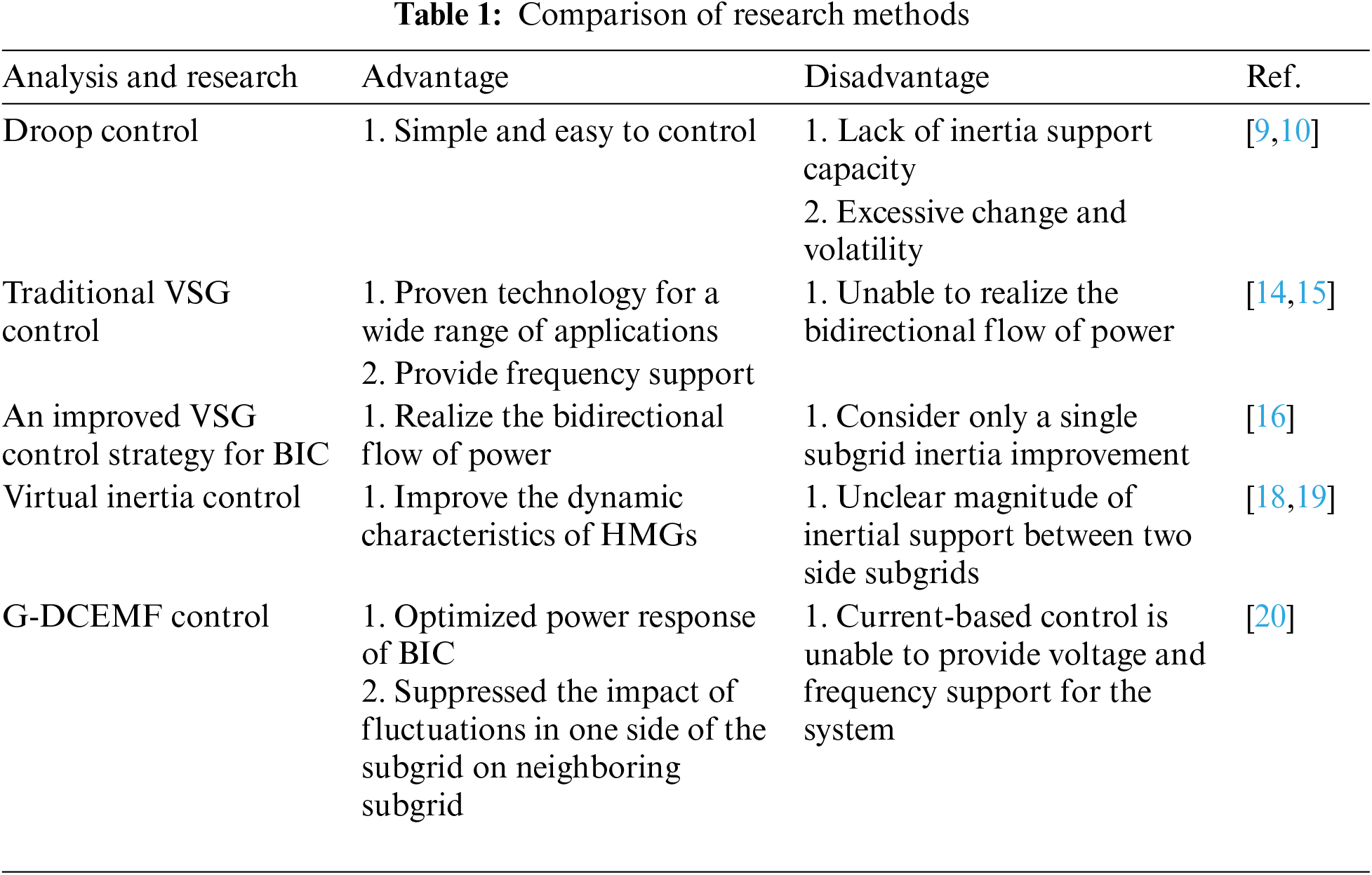
In conclusion, the control requirements for BICs face many new challenges. Table 1 lists the current mainstream control strategies for BICs. In view of the shortcomings of the above studies, this paper considers the inertia demand on both sides of the AC and DC and adopts
To address the bidirectional power transfer requirements, inertia deficit, and stability problems of HMGs, this paper improves the electric potential equation of a traditional DC motor and realizes power sharing and distribution using virtual resistors. For BIC, a
This paper proposes a BIC control strategy based on
(1) Innovative power allocation and bi-directional flow realization: The bi-directional power flow between subgrids is successfully realized by implementing virtual resistors for power sharing and allocation. Compared with other control techniques, this method only changes the external control loop of the converter without mode switching, which reduces the power loss and instability factors and effectively solves the deficiencies of the traditional control strategy in terms of the flexibility and stability of power allocation.
(2) Comprehensive voltage and frequency support and inertia provision: The proposed strategy can provide voltage and frequency support for the AC and DC buses and inertia for the AC and DC subgrids. This feature enables the AC/DC subgrid to share the disturbance effects by adjusting the virtual capacitance during sudden load changes, which improves the situation in which the traditional control strategy cannot consider the dynamic performance of both sides simultaneously.
(3) Improved dynamic response and anti-disturbance performance: Under load fluctuation, the
To confirm the efficacy of this control approach, a standard HMG system was built using PSCAD/EMTDC simulation software for this research.
This paper mainly discusses the BIC control of HMG in island mode. Fig. 1 shows the structure of AC-DC HMG. In the HMG, the offsets of AC frequency and DC bus voltage are the main metrics reflecting the amount of active power inequality in AC and DC MGs, respectively.
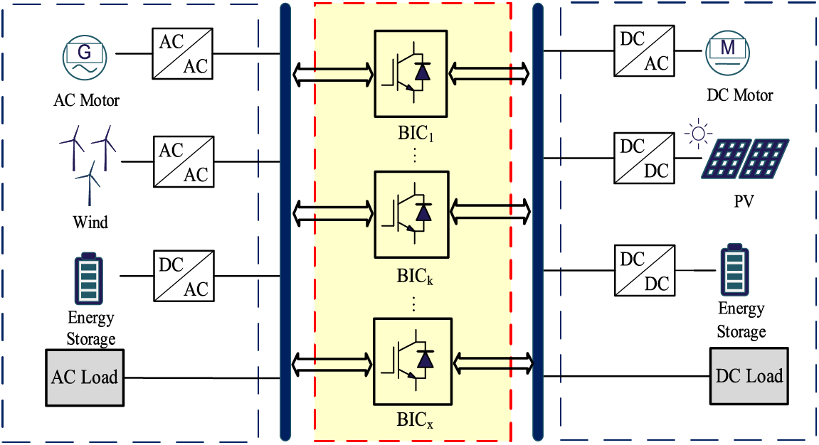
Figure 1: Structure diagram of HMG
Droop control has been used in both AC and DC MGs to balance the distribution of AC and DC active loads [21]. Traditional droop control enables power sharing and provides voltage and frequency support in HMGs, but it suffers from fast response and lack of inertia [22]. Virtual resistors and inductors have been proposed in the literature [20] for power distribution and inertia control via BIC-based generalized DC motor electromotive force (G-DCEMF) control. In Fig. 2, the G-DCEMF control model is displayed.
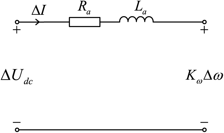
Figure 2: G-DCEMF control model
The G-DCEMF control equations are as follows:
where Ra is the virtual resistance, Kω is the electromotive force coefficient, ΔUdc is the DC voltage deviation, Δω is the AC frequency deviation, and ΔI is the deviation of the current flowing through the BIC.
Neglecting the virtual inductance La, the power-sharing of the G-DCEMF control for the BIC can be expressed as
In (2), Kω can be determined by
The values of Mu and Mω represent the permissible ranges for fluctuations in Udc and ω, respectively.
The active power reference value Pref of BIC can be obtained by
In the proposed G-DCEMF control, SN should be expressed as
As a result, the BIC’s virtual resistance Ra can be calculated using
Virtual capacitors are more suitable for voltage-based control, while virtual inductors used in G-DCEMF control are more suitable for current-based control. To realize sufficient voltage and frequency support for the HMG during islanding operation, virtual inductance in the G-DCEMF is converted to virtual capacitance, thus proposing
2.1 Active Power Loop Control of BIC
The mechanical motion equation of VSG is shown in (7).
where J is moment of inertia, Pm is mechanical power, and Pe is electromagnetic power.
For better integration with the G-DCEMF control, Eq. (7) can be transformed into
where
where Uω is the virtual voltage of the AC frequency converted to the DC side, and Cω is the virtual capacitor on the AC side.
In traditional VSG control, the dynamic response of AC frequency is considered, but the oscillation of DC voltage has not been considered. Consequently, a DC voltage control mode similar to (8) is proposed as
where Cu is the virtual capacitor on the DC side.
Likewise, taking into account the governing equation’s initial state, a
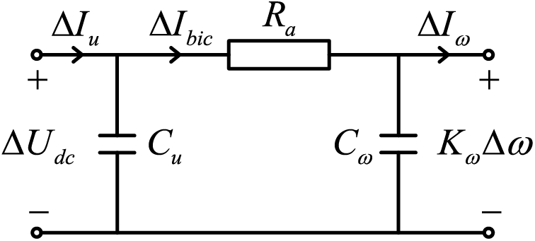
Figure 3: BIC
Based on Fig. 3, Eq. (11) can be obtained.
where
Combining (11) and (12), Eq. (13) can be obtained via Laplace transform.
The BIC transmission power is expressed as Eq. (14), which consists of a steady state component and a transient component. The transient component is the actively transmitted inertial power ΔPvir. The frequency will fall below the rate when there is a sudden rise in the AC load without an additional power supply. To give the AC frequency priority support, the BIC sends the inertial power ΔPvir to the AC subgrid. When the DC load grows significantly and no more power input is available, the BIC transfers inertial power ΔPvir to the DC subgrid to offer prioritised DC voltage support.
And because
where θ is the phase angle.
The control block diagram of the active loop of BIC can be obtained, as shown in Fig. 4.
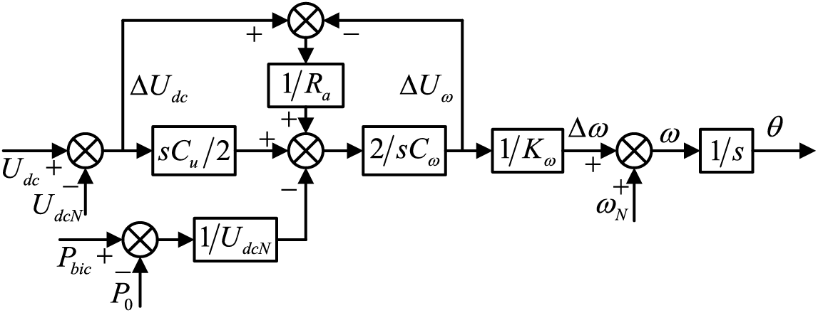
Figure 4: BIC
2.2 Reactive Power Loop Control of BIC
The reactive power loop of the BIC adopts reactive power-voltage (Q-V) droop control, and Eq. (16) is the excitation control of VSG.
where Em is the AC voltage amplitude reference value, KQ is the reactive inertia coefficient, Dq is the droop coefficient of Q-V control, Vn and V are the AC voltage amplitude and actual values, respectively, and Q0 and Qbic are the BIC reactive power initial and actual values, respectively.
The frequency and phase signal output by the active loop and the voltage amplitude signal output by the reactive loop can be synthesized into the reference voltage eabc by
2.3 Voltage and Current Double Closed-Loop Control of BIC
Fig. 5 is the voltage-current double closed-loop control diagram. When the BIC needs to ensure the stability of the HMG, the actual value of the BIC power transmission and the DC side bus voltage are synthesized to obtain the voltage reference value after passing through the
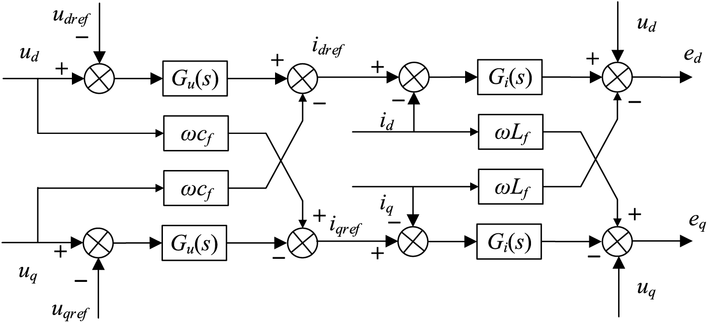
Figure 5: Voltage and current double closed-loop control model
The primary circuit, the
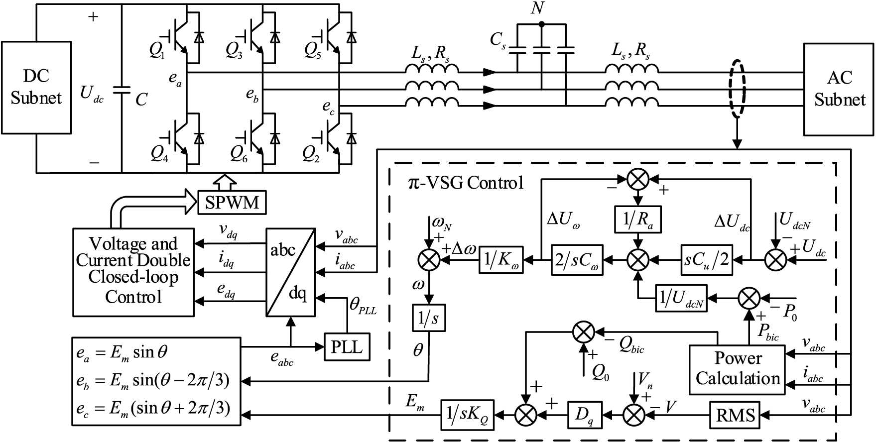
Figure 6: BIC
For the proposed
In the closed-loop control system of the BIC, the underlying voltage-current dual closed-loop control responds very rapidly with negligible response time compared to the response time of the
The BIC is comparable to a voltage source in series with an output impedance, whose reactance value is generally much greater than the resistance value. Thus, the BIC’s active power output may be expressed as
where KPδ is a constant coefficient, U is the output voltage amplitude, E is the amplitude of the output electromotive force of BIC, X is BIC equivalent output impedance, and δ, be expressed by (19), is the phase difference between the output electromotive force and the output voltage.
where ωg is the angular frequency of the output voltage.
The small signal model is formulated based on (13), (18), and (19) and eliminates the steady-state quantity. Due to sin δ ≈ δ and cos δ ≈ 1, the small signal model can be gotten as
In the DC subgrid, ignoring the small signal disturbance of the DC load, Eq. (21) can be obtained as
where kdc is the P-U droop coefficient of the DC subgrid.
According to (20) and (21), the active loop small signal model of BIC
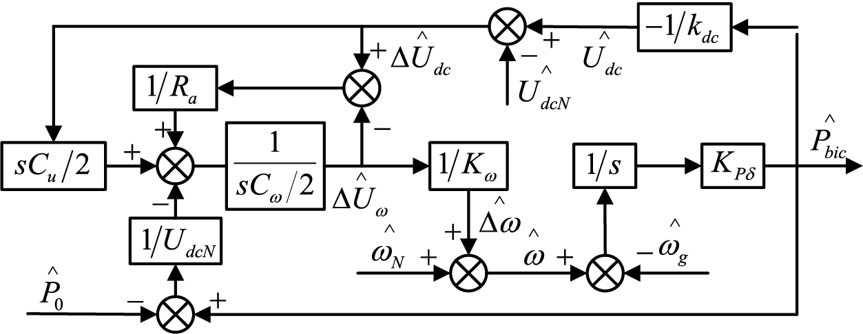
Figure 7: Active loop small signal model of BIC
In the small signal model, the small signal disturbances of UdcN, ωN and ωg can be set to 0, and then the closed-loop transfer function of active power can be obtained as
Assuming the denominator is zero, Eq. (22) can be transformed into
The left side of (18) can be regarded as the equivalent open-loop transfer function, where Cu is the root locus gain. When 1/Cω ranges from 0 to infinity, the pole distribution of the equivalent open-loop transfer function on the s plane is displayed in Fig. 8. It is clear that regardless of the value of Cω, the pole of the open-loop transfer function is always on the left half axis of the s plane. Beginning at the pole of the open-loop transfer function and ending at zero is the root locus of the closed-loop transfer function. There is a root locus that ends at negative infinity since the equivalent open-loop transfer function has two poles and one zero with a value of 0. In the s plane, the pole distribution of the Cu closed-loop transfer function from 0 to infinity is displayed in Fig. 9 for Cω values of 0.1, 1, and 10. So, in the
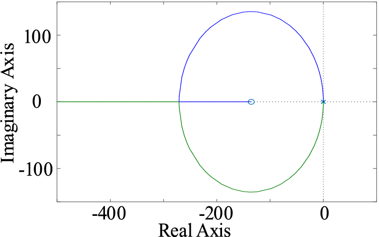
Figure 8: The pole distribution of the equivalent open-loop transfer function on the s plane
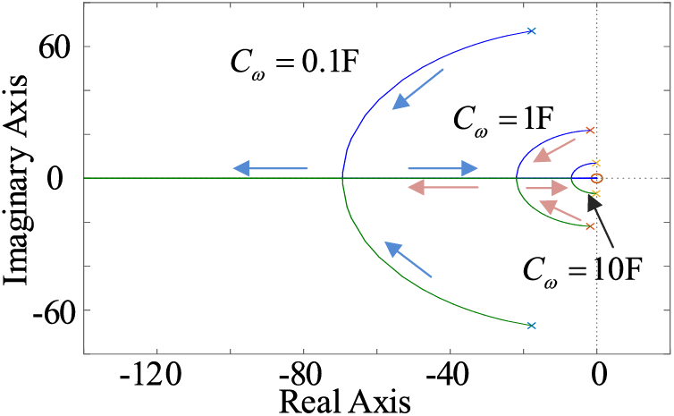
Figure 9: The pole distribution of the closed-loop transfer function on the s plane
3.2 Dynamic Response of AC Frequency and DC Voltage
In HMG, the load power variation ΔPL satisfies (24).
where kac is the P-ω droop coefficient of the AC subgrid, Δωac_L and ΔUdc_L are AC frequency variation and DC voltage variation caused by ΔPL, respectively.
The load power variation in the AC subgrid ΔPLac satisfies (25).
where ΔPi_Lac is the BIC power variation caused by ΔPLac.
In combination with (13) and (25), the AC frequency variation Δωac_Lac and the DC voltage variation ΔUdc_Lac caused by ΔPLac can be expressed as
where
Similarly, the load power variation in the DC subgrid ΔPLdc satisfies (28).
where ΔPbic_Ldc is the BIC power variation caused by ΔPLdc.
Hence, the AC frequency variation Δωac_Ldc and DC voltage variation ΔUdc_Ldc caused by ΔPLdc are
As shown, the values of Cω and Cu only influence the dynamic response, but the value of Ra influences the steady-state values of AC frequency and DC voltage, which are established by (6).
Ignoring the different terms between (26) and (29), the analysis can be simplified to
It is evident from (30) that in the event of a sudden change in the load power, both the AC frequency and the DC voltage will likewise change quickly. However, these changes will eventually recover to the new steady-state operation point. The increase of Cu will lead to the rise of bω0/a0 and the decrease of bu0/a0, which means that the sudden change of AC frequency will increase and the sudden change of DC voltage will decrease. When Cω increases, the AC frequency mutation decreases, and the DC voltage mutation increases. When Cu is 0, the AC frequency will change slowly, similar to the traditional VSG control. However, the sudden change of DC voltage reaches the maximum, which means that the DC bus voltage entirely bears the impact of the load power fluctuation. The proposed
According to Fig. 7, the closed-loop transfer function between Δω and Pbic can be obtained.
According to Fig. 7, the closed-loop transfer function between ΔUdc and Pbic can be obtained.
Fig. 10 gives the output power step response curves caused by the change of virtual capacitance on the AC and DC sides. As shown in Fig. 10a, when the virtual capacitance Cu on the DC side is kept constant, as Cω increases, it will bring some inertia to the system, but at the cost of an increase in the system’s overshoot; Fig. 10b shows that, by fixing the value of the virtual capacitance Cω on the AC side, the DC voltage overshoot will decrease as Cu increases, and at the same time accelerates the system back to a steady state.
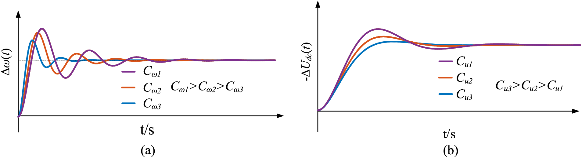
Figure 10: Step response curve of output power Pbic varying with control parameters
Furthermore, Mω0 and Mu0 are the maximum allowable fluctuation ranges of Udc and ω, respectively. The inequalities between Cu and Cω should be
If both AC frequency and DC voltage change rate must satisfy the conditions listed in (34) correspondingly.
where
Then, the values of Cu and Cω should also meet (35).
It can be seen from the previous analysis that the values of Cu and Cω not only provide inertia for the system but also affect the sudden change of AC frequency and DC voltage caused by ΔPL. The increase in Cu will lead to the sudden growth of the abrupt value of AC frequency and the sudden decrease of the abrupt value of DC voltage. The increase in Cω will lead to the sudden decrease of the abrupt value of AC frequency and the sudden increase of DC voltage. In general, the sudden change of DC bus voltage often has less impact on the subgrid than that of AC bus frequency.
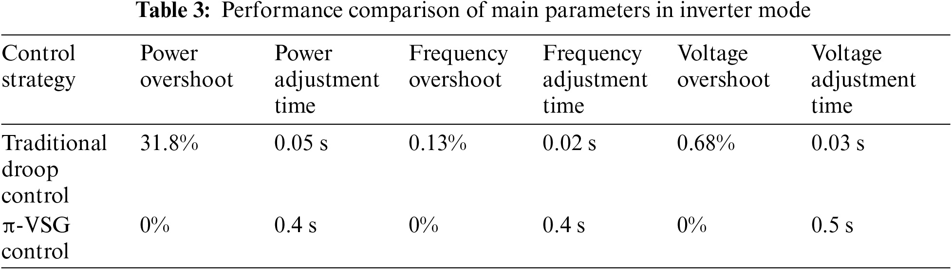
To test the efficacy of
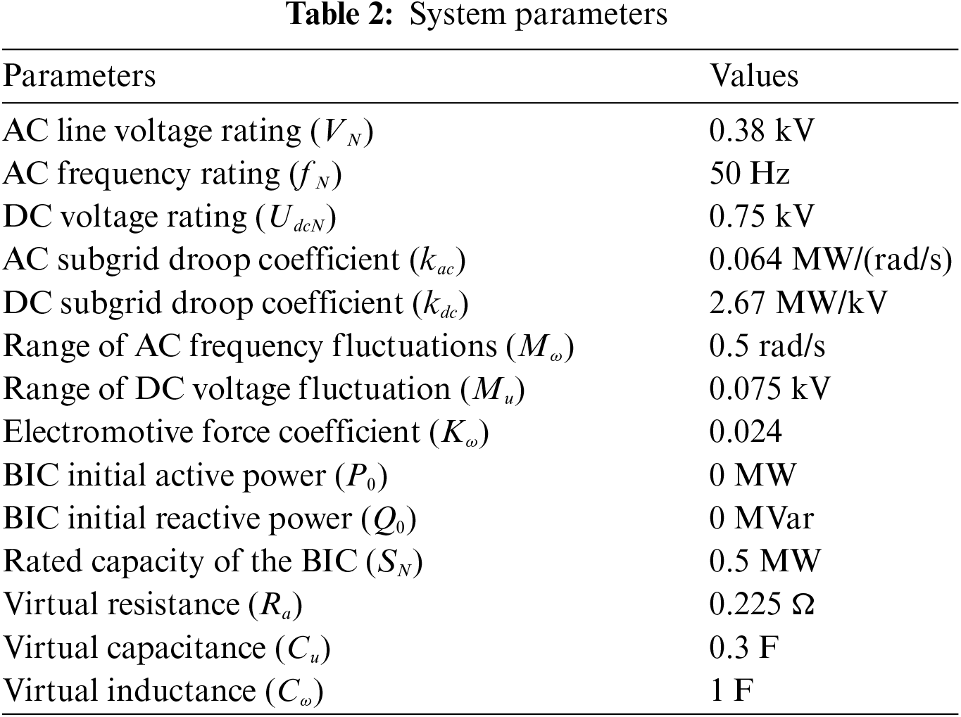
According to the former analysis, when Cu = 0 and Cω = 0, the BIC is under bidirectional droop control. Therefore, to compare different control modes more intuitively and keep other parameters unchanged in this paper, bidirectional droop control is simulated by setting Cu and Cω to 0. In the proposed
1) Inverter mode
At t = 2 s, the AC-side load increases by 100 kW; at t = 4 s, the AC-side load decreases by 100 kW. Fig. 11 shows the AC load change simulation diagrams containing the DC voltage, AC frequency, and transmitted active power, as well as the transmitted virtual inertia power waveforms under the bidirectional droop control and the
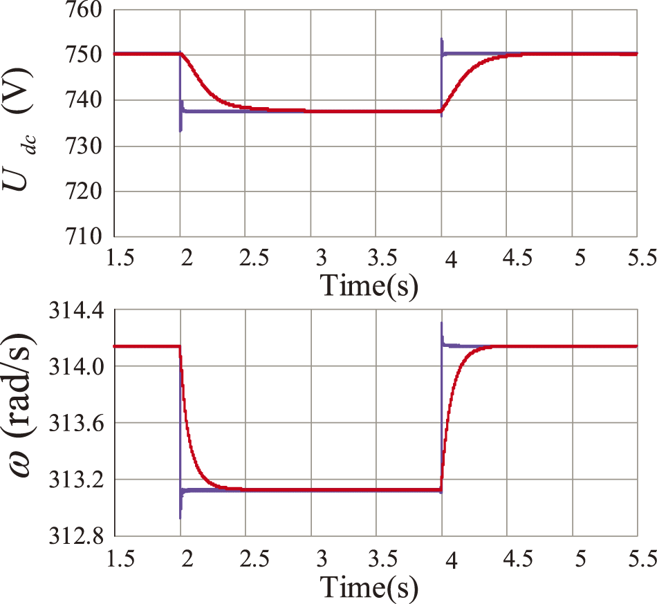
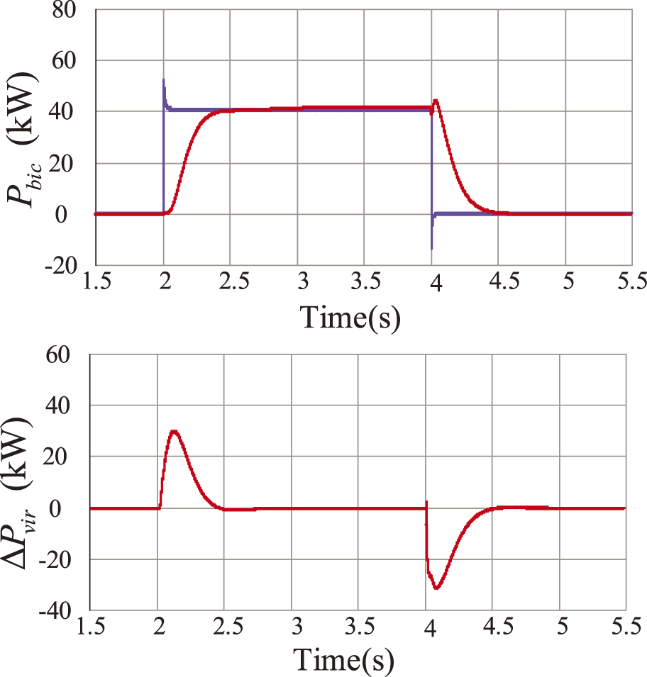
Figure 11: DC bus voltage, BIC active power, AC bus angular frequency waveforms, and virtual inertia power waveforms transferred between subgrids when 100 kW AC load input to the AC subgrid
2) Rectifier mode
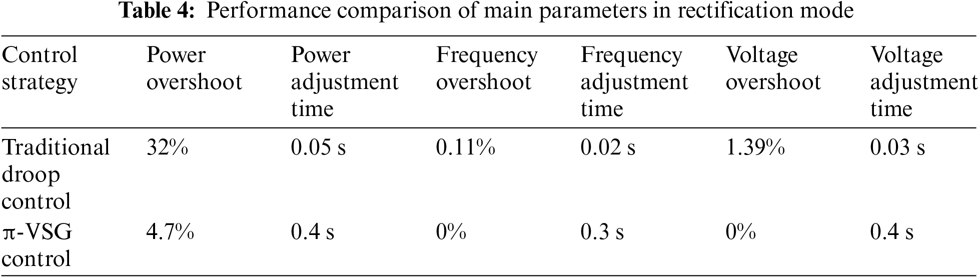
Similarly, at t = 2 s, the DC-side load increases by 100 kW; at t = 4 s, the DC-side load decreases by 100 kW. Fig. 12 shows the DC load change simulation diagrams containing the DC voltage, AC frequency, and transmitted active power, as well as the transmitted virtual inertia power waveforms under the bi-directional droop control and
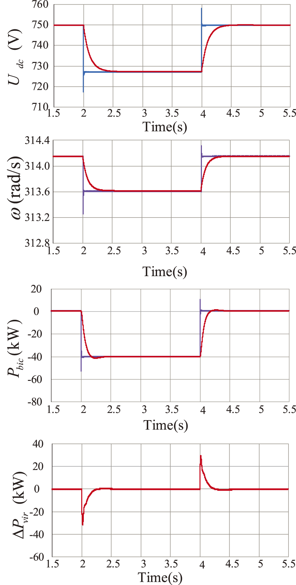
Figure 12: DC bus voltage, BIC active power, AC bus angular frequency waveforms, and virtual inertia power waveforms transferred between subgrids when 100 kW DC load input to the DC subgrid
3) Mode transition
At t = 2 s, a DC load of 50 kW is input to the DC subgrid. At t = 3 s, a 100 kW AC load is input to the AC subgrid. At 2~3 s, the BIC operates in rectifier mode, and the HMG shares the sudden DC load disturbance through the BIC. At 3~4.5 s, the AC subgrid is heavily loaded, and the BIC operates in inverter mode. The improvement in AC frequency and DC voltage inertia can also be realized during the mode-switching process. At t = 4.5 s, the AC and DC loads are removed, and after about 0.5 s, the system returns to the rated state, and the power transfer is 0. According to Fig. 13, it can be seen that the BIC can flexibly adjust the operation mode according to the changes of HMG measured loads to satisfy the requirement of the BIC’s power bidirectional transfer.
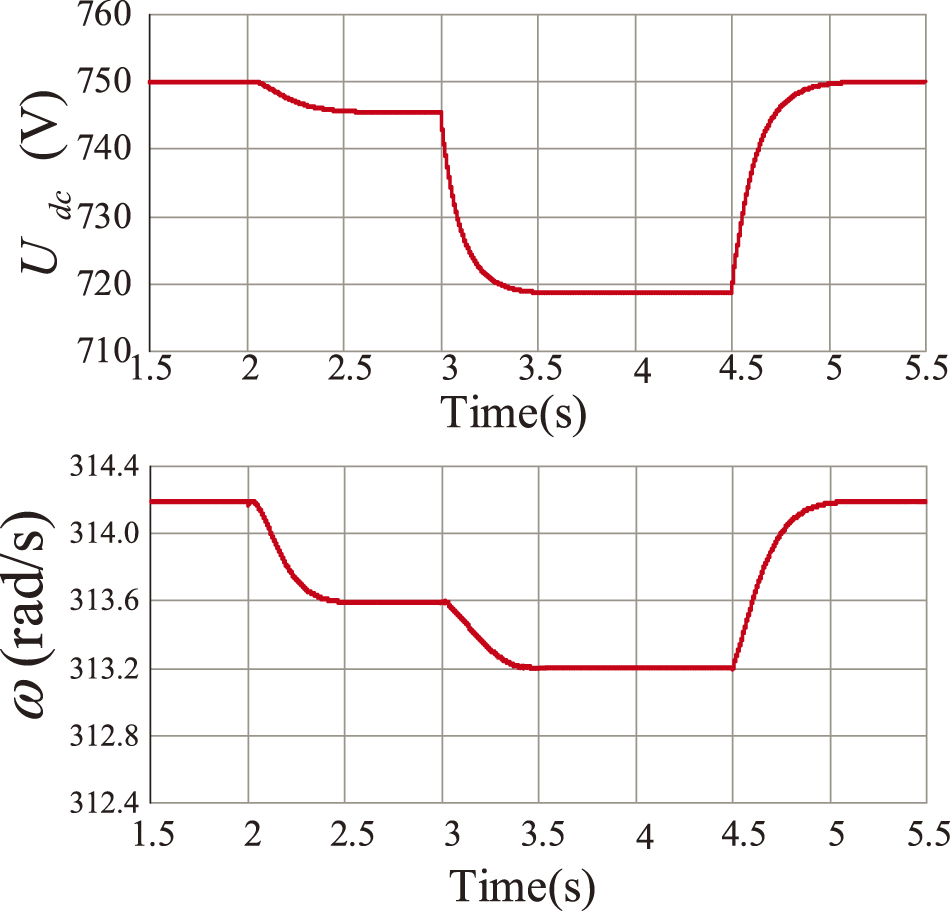
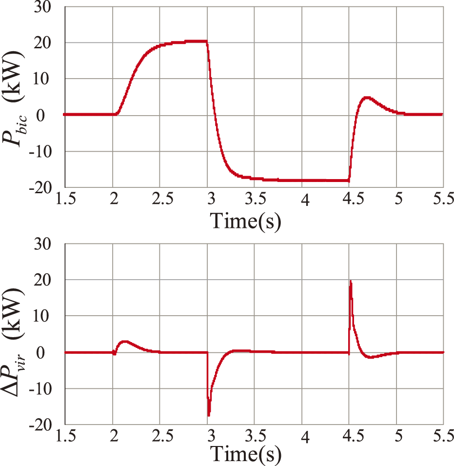
Figure 13: BIC mode transition simulation diagram
4) Power distribution
Meanwhile, to verify the power distribution ability of bidirectional virtual inertia augmentation control, it is known that the power transfer of BIC is related to virtual resistance. Setting the virtual resistance value ratio as R1:R2:R3 = 1:2:3, a 100 kW DC load is put in at t = 2 s to verify the power waveforms at different virtual resistance values. Set the ratio of virtual resistance values as R1:R2:R3 = 1:2:3, and at t = 2 s, put in 100 kW AC load to verify the power waveforms at different virtual resistance values. From Fig. 14, the BIC transmission power ratio is 3:2:1, and a flexible proportional transmission power distribution is realized.
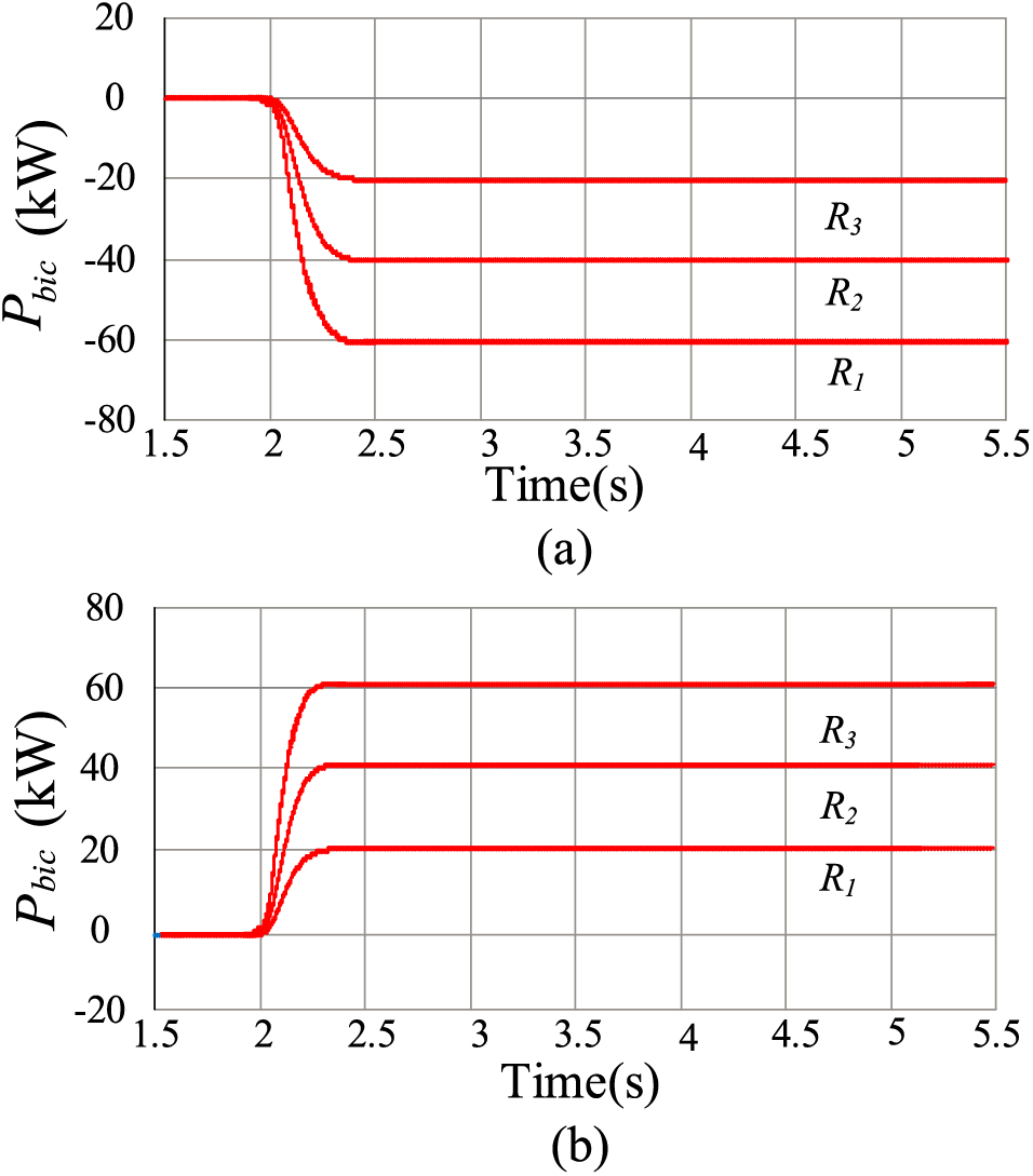
Figure 14: BIC power distribution simulation diagram
In summary, the proposed BIC
The transfer of virtual inertia between subgrids is a way to improve the stability of the HMG system by balancing the individual subgrids through BIC control. This approach enables and improves the transient performance on both sides of the system. So, in this paper, the
(1) BIC’s power-sharing can be flexibly controlled by using virtual resistance, which facilitates the optimization of power transfer in the islanded HMG system.
(2) The
(3) The power distribution and dynamic response of the BIC can be adapted to different operating modes. The virtual inertia parameters Cω and Cu provide inertial support for AC and DC subgrids without affecting the steady-state values of the control system.
Meanwhile, future work and research directions are as follows:
(1) Parameter optimization research: further explore the optimization methods of virtual capacitance Cω and Cu, virtual resistance Ra to adapt to more complex operating conditions.
(2) Research on parallel operation of multiple machines: for parallel operation of multiple machines, in-depth research on their interaction and coordination control methods to ensure the stability and reliability of the system in large-scale applications.
(3) Combination with other control strategies: Consider combining the
Acknowledgement: None.
Funding Statement: This research was funded by “The Fourth Phase of 2022 Advantage Discipline Engineering-Control Science and Engineering”, grant number 4013000063.
Author Contributions: The authors confirm their contribution to the paper as follows: study conception and design: Dongyang Yang; data collection: Kai Shi; analysis and interpretation of results: Dongyang Yang, Kai Shi; draft manuscript preparation: Dongyang Yang. All authors reviewed the results and approved the final version of the manuscript.
Availability of Data and Materials: The authors confirm that the data used in this study are available on request.
Ethics Approval: Not applicable.
Conflicts of Interest: The authors declare no conflicts of interest to report regarding the present study.
References
1. X. R. Xie, J. B. He, H. Y. Mao, and H. Z. Li, “Discussion on new issues and categorization of “double-high” power system stability,” Chin. J. Electr. Eng., vol. 41, no. 10, pp. 461–475, Nov. 2021. doi: 10.13334/j.0258-8013.pcsee.201405. [Google Scholar] [CrossRef]
2. A. A. Eajal, A. H. Yazdavar, E. F. El-Saadany, and M. M. A. Salama, “Optimizing the droop characteristics of hybrid AC/DC MGs for precise power sharing,” IEEE Syst. J., vol. 15, no. 1, pp. 560–569, Mar. 2021. doi: 10.1109/JSYST.2020.2984623. [Google Scholar] [CrossRef]
3. F. Sayeed et al., “A novel and comprehensive mechanism for the energy management of a hybrid micro-grid system,” Energy Rep., vol. 8, no. 5, pp. 847–862, Nov. 2022. doi: 10.1016/j.egyr.2022.09.207. [Google Scholar] [CrossRef]
4. A. O. Rousis, I. Konstantelos, and G. Strbac, “A planning model for a hybrid AC-DC microgrid using a novel GA/AC OPF algorithm,” IEEE Trans. Power Syst., vol. 35, no. 1, pp. 227–237, Jan. 2020. doi: 10.1109/TPWRS.2019.2924137. [Google Scholar] [CrossRef]
5. Y. Wang, A. O. Rousis, and G. Strbac, “Resilience-driven modeling, operation and assessment for a hybrid AC/DC microgrid,” IEEE Access, vol. 8, pp. 139756–139770, 2020. doi: 10.1109/ACCESS.2020.3013662. [Google Scholar] [CrossRef]
6. Z. Liu, S. Miao, W. Wang, and D. Sun, “Comprehensive control scheme for an interlinking converter in a hybrid AC/DC MG,” CSEE J. Power Energy Syst., vol. 7, no. 4, pp. 719–729, Jul. 2021. doi: 10.17775/CSEEJPES.2020.00970. [Google Scholar] [CrossRef]
7. X. Shen, D. Tan, Z. Shuai, and A. Luo, “Control techniques for bidirectional interlinking converters in hybrid microgrids: Leveraging the advantages of both ac and dc,” IEEE Power Electron. Mag., vol. 6, no. 3, pp. 39–47, Sep. 2019. doi: 10.1109/MPEL.2019.2925298. [Google Scholar] [CrossRef]
8. Z. Gao, C. Li, Y. Liu, C. Tian, W. Teng and Y. Rao, “Bidirectional droop control of AC/DC hybrid MG interlinking converter,” in Proc. 2nd Int. Conf. Saf. Produce Inf. (IICSPI), 2019, pp. 213–217. doi: 10.1109/IICSPI48186.2019.9095894. [Google Scholar] [CrossRef]
9. S. Peyghami, H. Mokhtari, and F. Blaabjerg, “Autonomous operation of a hybrid AC/DC MG with multiple interlinking converters,” IEEE Trans. Smart Grid, vol. 9, no. 6, pp. 6480–6488, Nov. 2018. doi: 10.1109/TSG.2017.2713941. [Google Scholar] [CrossRef]
10. M. Ahmed, L. Meegahapola, M. Datta, and A. Vahidnia, “A novel hybrid AC/DC microgrid architecture with a central energy storage system,” IEEE Trans. Power Deliv., vol. 37, no. 3, pp. 2060–2070, Jun. 2022. doi: 10.1109/TPWRD.2021.3103742. [Google Scholar] [CrossRef]
11. J. Wang, C. Jin, and P. Wang, “A uniform control strategy for the interlinking converter in hierarchical controlled hybrid AC/DC microgrids,” IEEE Trans. Ind. Electron., vol. 65, no. 8, pp. 6188–6197, Aug. 2018. doi: 10.1109/TIE.2017.2784349. [Google Scholar] [CrossRef]
12. M. Najafzadeh, R. Ahmadiahangar, O. Husev, I. Roasto, T. Jalakas and A. Blinov, “Recent contributions, future prospects and limitations of interlinking converter control in hybrid AC/DC microgrids,” IEEE Access, vol. 9, pp. 7960–7984, Jan. 2021. doi: 10.1109/ACCESS.2020.3049023. [Google Scholar] [CrossRef]
13. G. Melath, S. Rangarajan, and V. Agarwal, “A novel control scheme for enhancing the transient performance of an islanded hybrid AC-DC microgrid,” IEEE Trans. Power Electron., vol. 34, no. 10, pp. 9644–9654, Oct. 2019. doi: 10.1109/TPEL.2019.2891637. [Google Scholar] [CrossRef]
14. K. Shi, W. Song, H. Ge, P. Xu, Y. Yang and F. Blaabjerg, “Transient analysis of microgrids with parallel synchronous generators and virtual synchronous generators,” IEEE Trans. Energy Convers., vol. 35, no. 1, pp. 95–105, Mar. 2020. doi: 10.1109/TEC.2019.2943888. [Google Scholar] [CrossRef]
15. K. Shi, Y. Wang, Y. Sun, P. Xu, and F. Gao, “Frequency-coupled impedance modeling of virtual synchronous generators,” IEEE Trans. Power Syst., vol. 36, no. 4, pp. 3692–3700, Jul. 2021. doi: 10.1109/TPWRS.2021.3050568. [Google Scholar] [CrossRef]
16. C. Jin, C. Jia, J. Fu, and S. Wang, “Inertia control and dynamic performance optimization of interlinking converter based on parameter adaptation,” in 2022 Asian Conf. Front. Pow. Energy (ACFPE), Chengdu, China, 2022, pp. 489–493. doi: 10.1109/ACFPE56003.2022.9952343. [Google Scholar] [CrossRef]
17. A. Hosseinipour and H. Hojabri, “Virtual inertia control of PV systems for dynamic performance and damping enhancement of DC MGs with constant power loads,” IET Renew. Pow. Generat., vol. 12, no. 4, pp. 430–438, Jan. 2018. doi: 10.1049/iet-rpg.2017.0468. [Google Scholar] [CrossRef]
18. Z. W. Liu, S. H. Miao, Z. H. Fan, J. Y. Liu, and Q. Y. Tu, “lmproved power flow control strategy of the hybrid AC/DC microgrid based on VSM,” IET Generat., Transmiss. Distribut., vol. 13, no. 1, pp. 81–91, Dec. 2018. doi: 10.1049/iet-gtd.2018.5839. [Google Scholar] [CrossRef]
19. J. R. Shi, Y. Li, L. He, Z. Y. Wang, and S. Q. Jiao, “An integrated inertia control method to enhance the dynamic characteristics of AC-DC hybrid microgrid,” J. Electrotechnol., vol. 35, no. 2, pp. 337–345, Jan. 2020. doi: 10.19595/j.cnki.1000-6753.tces.181573. [Google Scholar] [CrossRef]
20. K. Shi, Y. Chen, P. Xu, Y. Sun, M. Liu and X. Wang, “A generalized DC electromotive force control strategy for Bi-directional interface converters in a standalone hybrid microgrid,” IEEE Trans. Energy Convers., vol. 38, no. 2, pp. 1155–1165, Jun. 2023. doi: 10.1109/TEC.2022.3229272. [Google Scholar] [CrossRef]
21. J. Wang, W. Huang, N. Tai, M. Yu, R. Li and Y. Zhang, “A bidirectional virtual inertia control strategy for the interconnected converter of standalone AC/DC hybrid microgrids,” IEEE Trans. Power Syst., vol. 39, no. 1, pp. 745–754, Jan. 2024. doi: 10.1109/TPWRS.2023.3246522. [Google Scholar] [CrossRef]
22. L. He, Y. Li, J. M. Guerrero, and Y. Cao, “A comprehensive inertial control strategy for hybrid AC/DC microgrid with distributed generations,” IEEE Trans. Smart Grid, vol. 11, no. 2, pp. 1737–1747, Mar. 2020. doi: 10.1109/TSG.2019.2942736. [Google Scholar] [CrossRef]
Cite This Article
 Copyright © 2025 The Author(s). Published by Tech Science Press.
This work is licensed under a Creative Commons Attribution 4.0 International License , which permits unrestricted use, distribution, and reproduction in any medium, provided the original work is properly cited.
 Downloads
 Citation Tools