
 Submit a Paper
 Propose a Special lssue
 Open Access
ARTICLE

Design and Development of a Small-Scale Green Hydrogen Vehicle: Hydrogen Consumption Analysis under Varying Loads for Zero-Emission Transport
1 Research Centre for Sustainable Technologies, Faculty of Engineering, Computing and Science, Swinburne University of Technology, Jalan Simpang Tiga, Kuching, 93350, Sarawak, Malaysia
2 College of Engineering, Faculty of Computing, Engineering and the Built Environment, Birmingham City University, Birmingham, B4 7XG, UK
* Corresponding Author: Hadi Nabipour Afrouzi. Email:
Energy Engineering 2025, 122(5), 1789-1804. https://doi.org/10.32604/ee.2025.060124
Received 24 October 2024; Accepted 28 February 2025; Issue published 25 April 2025
 View Full Text
 Download PDF
Abstract
With growing interest in its potential applications across both stationary and transportation sectors, hydrogen has emerged as a promising alternative for environmentally responsible power generation. By replacing traditional fuels, hydrogen can significantly reduce greenhouse gas emissions in the transportation sector. This study focuses on the design and downsizing of a green hydrogen fuel cell car, aiming to scale the concept for larger vehicles. Key components, including fuel cells, electrolysers, and solar panels, were evaluated through extensive laboratory testing. The findings reveal that variations in sunlight impact the solar panel’s hydrogen production rate, with differences of approximately 4.9% attributed to changes in time and date. Analysis of consumption rates showed that a 17.4% increase in current consumption leads to a significant reduction in operational time. Further testing under varying loads demonstrated that higher current demands, such as those from a DC motor, accelerate hydrogen depletion, whereas lower currents extend operational duration. These results underscore the importance of maximizing solar energy efficiency, reducing reliance on conventional energy sources, and regulating consumption rates to optimize fuel cell performance. Since hydrogen is produced using renewable energy, fuel cell technology is virtually emission-free. Additionally, the study highlights the viability of powering vehicles with renewable energy, emphasizing the potential of green hydrogen fuel cell technology as a sustainable transportation solution.Graphic Abstract
Keywords
In 1788, the distinguished British scientist Henry Cavendish made a groundbreaking discovery by isolating hydrogen gas through a chemical reaction between zinc metal and hydrochloric acid. This significant achievement led to the identification of hydrogen as a distinct element. Moreover, this revelation enabled him to uncover the composition of water (H2O), demonstrating that it consists of hydrogen and oxygen. The year 1800 marked a pivotal moment in the field of chemistry when English scientists William Nicholson and Sir Anthony Carlisle coined the term “electrolysis.” They achieved this by applying an electric current to water, resulting in the production of both hydrogen and oxygen gases. In 1839, Swiss chemist Christian Friedrich Schönbein made a remarkable discovery known as the “fuel cell effect,” which involved combining hydrogen and oxygen to generate electricity. Building on Schönbein’s findings, Sir William Grove transformed this scientific breakthrough into a practical application. By creating a gas battery, he earned the title of the “Father of the Fuel Cell” [1].
Fossil fuels have long served as the primary energy source in developed countries. However, with the global population increasing, there is an urgent need to transition to more sustainable energy sources to protect the environment and ensure long-term ecological balance [2]. Therefore, renewable energy has emerged as a leading source for electricity production. Known for its clean and recyclable properties, renewable energy holds immense potential for future development, offering a sustainable alternative to traditional energy sources [3]. The six principal sources of renewable energy are solar energy, wind energy, geothermal energy, hydropower, ocean energy, and bioenergy [4]. The primary motivation for generating electricity through renewable sources lies in their ability to produce zero greenhouse gas emissions and reduce air pollution [5]. Recently, another promising renewable energy source gaining attention is hydrogen energy. Hydrogen is increasingly recognized as a potential replacement for conventional fuels, offering the promise of a greener alternative with zero emissions, as its only by-products are heat and water vapor [6,7]. In addition to the aforementioned renewable energy options, another promising trend in the energy sector is the utilization of hydrogen energy. Hydrogen has emerged as a leading contender for future fuel applications due to its numerous advantages. For instance, it offers the potential to achieve zero emissions in road transportation, enhances the driving range of vehicles, facilitates the decarbonization of industrial sectors, boasts ease of storage and utilization, and even finds utility in space travel [8,9]. Therefore, hydrogen has the potential to be a key solution to climate change and a pivotal energy source for transitioning toward a sustainable energy future [10]. A fuel cell operates by using hydrogen as fuel to generate electricity and heat. A catalyst splits hydrogen into protons and electrons, with the electrons providing electrical power through an external circuit. The protons move to the cathode, where they combine with oxygen, producing electricity, water, and heat [11].
When comparing hydrogen to conventional solid fuels, a remarkable disparity in energy density becomes evident. Hydrogen boasts an impressive energy density of 140 MJ/kg, significantly surpassing the 50 MJ/kg offered by solid fuels. The versatility of hydrogen as an energy source further highlights its appeal, as it can be produced from both renewable and non-renewable sources. For example, hydrogen can be generated through various processes, including fossil fuel extraction, steam reforming of methane, oil or naphtha reforming, coal gasification, biomass conversion, biological sources, and water electrolysis.
When discussing hydrogen production, it is essential to note that a significant 96% of global hydrogen is currently produced from non-renewable sources, primarily through steam reforming of methane. Unfortunately, this method yields lower-purity hydrogen and generates substantial amounts of harmful greenhouse gases as by-products. Consequently, water electrolysis stands out as the most promising method for producing high-purity hydrogen, with the potential to achieve purity levels as high as 99.999%. A global evaluation reveals that South Korea (19,270 vehicles) and the United States (12,283 vehicles) lead the world in fuel-cell vehicle adoption. Passenger cars dominate the market, accounting for 82% of the share, followed by buses at 9.2% and trucks at 8.7% [12].
Researchers are actively exploring alternative low-cost electrocatalysts, improved efficiency, and energy-saving techniques. Their goal is to address the challenges of high energy consumption and low hydrogen evolution rates, thereby contributing to a cleaner and more sustainable future for hydrogen production [13]. In this project, several research questions need to be explored, as outlined below:
1. What are the types of water electrolysis?
2. What are the types of fuel cell?
3. Is solar panel feasible to be combined with hydrogen technologies?
4. What are the components required to build a hydrogen fuel cell car?
5. What is the best configuration for a solar hydrogen fuel cell car?
6. Do we need to include battery into the solar hydrogen fuel cell car?
The overarching objective of this project is to develop a practical and innovative green hydrogen fuel cell car by designing and implementing real-life hydrogen vehicle concepts. To achieve this goal, we will begin with a comprehensive review of existing literature and technologies to acquire the essential knowledge required for building a green hydrogen fuel cell car. This foundational understanding will guide our design choices and technical decisions. Next, we will focus on the meticulous design and construction of a functional prototype, drawing inspiration from real-world hydrogen vehicle designs. The aim is to demonstrate the feasibility of integrating solar and hydrogen technologies for sustainable transportation. Additionally, an in-depth analysis will be conducted to identify the most efficient configuration for the small-scale system, with a strong emphasis on optimizing efficiency, performance, and reliability. By pursuing these objectives, this project aspires not only to create a functional green hydrogen fuel cell car but also to contribute to the advancement of sustainable transportation technology. This aligns with global efforts to promote clean and eco-friendly alternatives. The following section of the research will be structured as follows:
• Section 2: Literature Review—Review relevant to electrolyser and fuel cell technology
• Section 3: Methodology—The idea of designing the green hydrogen fuel cell car
• Section 4: Result and Discussion—Review and discuss the finding throughout the lab
• Section 5: Conclusion—Conclude the research and recommend future work
Through comprehensive analysis, this research aims to offer valuable insights into hydrogen energy and contribute to the advancement of sustainable transportation technology.
2.1 Proton Exchange Membrane Water Electrolysis (PEMWE)
Fig. 1 illustrates the working principle of the Proton Exchange Membrane Water Electrolyzer (PEMWE). The PEMWE was developed to address the limitations of alkaline water electrolysis. Polysulfonated membranes, such as Nafion or Fumapem, are commonly used as electrolytes, serving as excellent proton conductors in the Proton Exchange Membrane (PEM). PEMs offer several advantages, including lower gas permeability, higher proton conductivity, a more compact design, and the ability to operate at high pressures. Furthermore, the Proton Exchange Membrane Electrolyzer (PEME) is highly compatible with renewable energy solutions due to its superior efficiency and a lifespan of approximately 10 years, Arunachalam et al. [14].The PEMWE is the preferred method for converting renewable energy into high-purity hydrogen due to its compact design, high current density (above 2 A/cm2), exceptional efficiency, rapid response, small footprint, operation at lower temperatures (20–80 degrees Celsius), and production of ultra-pure hydrogen. The electrocatalysts used in PEMWE are high-activity noble metals, such as platinum (Pt) or palladium (Pd) for the hydrogen evolution reaction (HER) at the cathode, and iridium oxide (IrO2) or ruthenium oxide (RuO2) for the oxygen evolution reaction (OER) at the anode. As a result, this component is more expensive compared to alkaline water electrolysis. Currently, the primary objective for PEMWE is to reduce manufacturing costs while maintaining its high efficiency [13]. PEM electrolyzers are highly sensitive to water contaminants. As a result, it is essential to conduct desalination and demineralization processes before initiating the electrolysis process. Using saline water in electrolysis can lead to the formation of chlorine instead of oxygen [15]. The working principle of the PEMWE is straightforward. At the anode, water molecules are split into oxygen (O2), protons (H+), and electrons (e−). Oxygen is released at the anode, while protons pass through the proton-conducting membrane. Electrons flow through an external circuit, and at the cathode, they recombine with protons to produce hydrogen gas (H2) [16,17].
Figure 1: Working principle of PEMWE
2.2 Proton Exchange Membrane Fuel Cell (PEMFC)
Fuel cells (FCs) are devices that generate direct current (DC) electricity by converting chemical energy through electrochemical reactions. In most fuel cells, hydrogen serves as the energy source and undergoes oxidation at the anode, splitting into protons and electrons [18]. Due to its efficiency, power density, and durability, the Proton Exchange Membrane Fuel Cell (PEMFC) is currently the fuel cell technology that has attracted the most attention from the automotive industry and stationary applications [19,20]
Referring to Fig. 2, it is evident that as hydrogen flows to the anode, it splits into two hydrogen ions and two electrons. The hydrogen ions migrate through the membrane, while the electrons travel through the external circuit to the cathode. At the cathode, these electrons combine oxygen and hydrogen ions, resulting in the production of water as a byproduct. The chemical equation illustrating the operation of a PEMFC is presented below:
Figure 2: Working illustration of PEMFC
A PEMFC consists of bipolar plates and a membrane electrode assembly (MEA). The MEA, in turn, comprises three essential layers: a dispersed catalyst layer, a carbon cloth or gas diffusion layer, and a proton-conducting membrane. Within the PEMFC, protons migrate from the anode to the cathode through the membrane while effectively blocking the passage of electrons and reactants. The gas diffusion layer ensures uniform fuel flow, enabling electrons to travel through the external circuit and generate electricity. PEMFCs are classified as low-temperature fuel cells, operating within a range of 60 to 100 degrees Celsius. These fuel cells offer several advantages, including rapid start-up times, extended lifetimes, and cost-effective manufacturing. Higher operating temperatures can improve efficiency due to enhanced reaction rates. However, exceeding 100 degrees Celsius can cause membrane dehydration, which reduces proton conductivity. The efficiency of PEMFCs typically ranges from 40% to 50%, and they can generate output power of up to 250 kW. These characteristics make PEMFCs highly suitable for transportation applications, where continuous electrical energy is essential, and they require minimal maintenance [21]. The PEMFC is commonly used in transportation applications, such as cars and buses, as well as in portable electronics, backup power systems, and small stationary power units [22].
2.3 Hydrogen Production Method
This study’s approach to hydrogen production will primarily focus on utilizing solar energy. Solar energy has been widely adopted for hydrogen generation. The photovoltaic (PV) system will generate electricity, which will then be used in conjunction with an electrolszer to separate hydrogen and oxygen from water. However, it is important to note that solar energy has limitations in meeting production demands, as it is only available during daylight hours and is susceptible to issues such as shading and temperature fluctuations. The schematic diagram for hydrogen production using solar energy is illustrated in Fig. 3. This diagram will serve as a visual aid to support the research on harnessing solar energy for hydrogen production [22].
Figure 3: Schematic diagram of Hydrogen production from solar energy
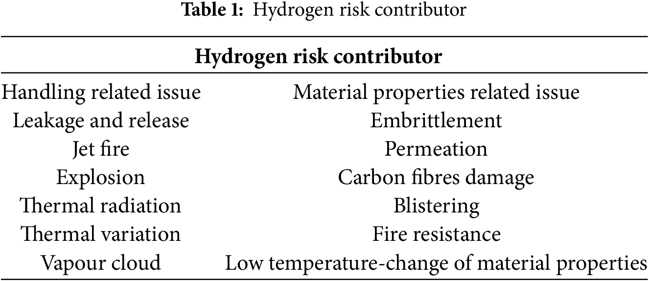
Hydrogen has been proven to be safer than conventional fuels such as petrol or natural gas. Due to its extremely low density, hydrogen disperses rapidly into the atmosphere if it leaks, significantly reducing the risk of explosion [23]. Hydrogen is a non-toxic gas that poses no direct risk to human health. However, certain safety concerns must still be addressed when handling hydrogen fuel. Table 1 outlines the risks associated with hydrogen. Consequently, further research is needed to mitigate these risks and implement effective safety measures for hydrogen applications [24]. As presented in Table 2, these are key studies, findings, and future research directions from the reviewed literature.

The initial phase of the project involves pre-modelling to identify the parameters for creating a green hydrogen fuel cell car. This is achieved through a review of literature or the design of a prototype fuel cell car. Understanding the electrolyser type, fuel cell type, and storage options for implementation into the small-scale green hydrogen fuel cell car is crucial. The design specifies a green hydrogen fuel cell car requiring three main components: a solar panel, an electrolyser, and a fuel cell.
The solar panel used in the research is a monocrystalline solar panel (FIT0601) with a voltage and current rating of 5 V and 1 A, respectively. This solar panel was selected due to its appropriate size for the small-scale car, roughly equivalent to the dimensions of an A4 paper (21.0 cm × 29.7 cm). Additionally, it is very lightweight, weighing only 90 g.
The electrolyser employed in the research is a double reversible fuel cell (R104). This fuel cell can operate in two modes: electrolyser mode and fuel cell mode. In electrolyser mode, it functions as a hydrogen and oxygen generator, capable of producing 20 mL of hydrogen gas and 10 mL of oxygen per minute when supplied with DC voltage. The fuel cell can handle a power input of up to 5.5 W, with a permissible current of up to 1.5 A. The double reversible fuel cell weighs 63 g [26]. In fuel cell mode, it can operate in both H2/O2 and H2/Air modes. In H2/O2 operation, the fuel cell can generate 1 W of power and 750 mA of current. In H2/Air operation, the output power and current are slightly lower, at 400 mW and 300 mA, respectively. This project will utilize one set of this component. The term “reversible fuel cell” is aptly used because it can function both as an electrolyser and as a fuel cell. Being a double reversible fuel cell, it has the advantage of producing more hydrogen and oxygen compared to a single reversible fuel cell. Although the double reversible fuel cell is versatile enough to operate in both electrolyser mode and fuel cell mode, it will exclusively serve as an electrolyser in this project, dedicated to the production of hydrogen and oxygen. This choice is motivated by its commendable production rate, compact form factor, and lightweight design, which align seamlessly with the project’s requirements.
The fuel cell selected for the research is the Quattro fuel cell (F105). This particular fuel cell is capable of operating in both H2/O2 and H2/Air modes. Notably, the fuel cell configuration consists of four cells integrated into a single module. In H2/O2 mode, the fuel cell exhibits an output power ranging from 2.4 to 2.6 W, accompanied by an output current of 1.5 A. Conversely, during H2/Air operation, the output power ranges from 720 to 800 mW, with an output current of 375 mA. The overall weight of the module is 78 g [27]. The selection of this fuel cell is grounded in its impressive output power capabilities and lightweight construction, both of which are crucial factors for this project.
During the modelling phase, the process begins with lab testing and the design of the car setup. The primary objective of lab testing is to gain a comprehensive understanding of the components required for constructing the green hydrogen fuel cell car. After this verification, additional components will be incorporated into the construction of the solar hydrogen fuel cell vehicle. These components include a buck converter, a boost converter, an MX1508 motor controller, a Nano microcontroller, two 47 µF capacitors, two N20 DC motors, a hydrogen storage tank, and an oxygen storage tank.
As shown in Fig. 4, the front half of the green hydrogen fuel cell car is connected as follows: The solar panel is linked to a buck converter to reduce the output voltage of the solar panel. This step is crucial because the permissible voltage for the electrolyser is approximately 3.7 V. To ensure that the voltage supplied to the electrolyser does not exceed this limit, the buck converter steps down the 5 V output to 3.7 V. The electrolyser is then connected to a 30 mL storage tank, enabling continuous production of hydrogen and oxygen when the solar panel is connected to the electrolyser via the buck converter.
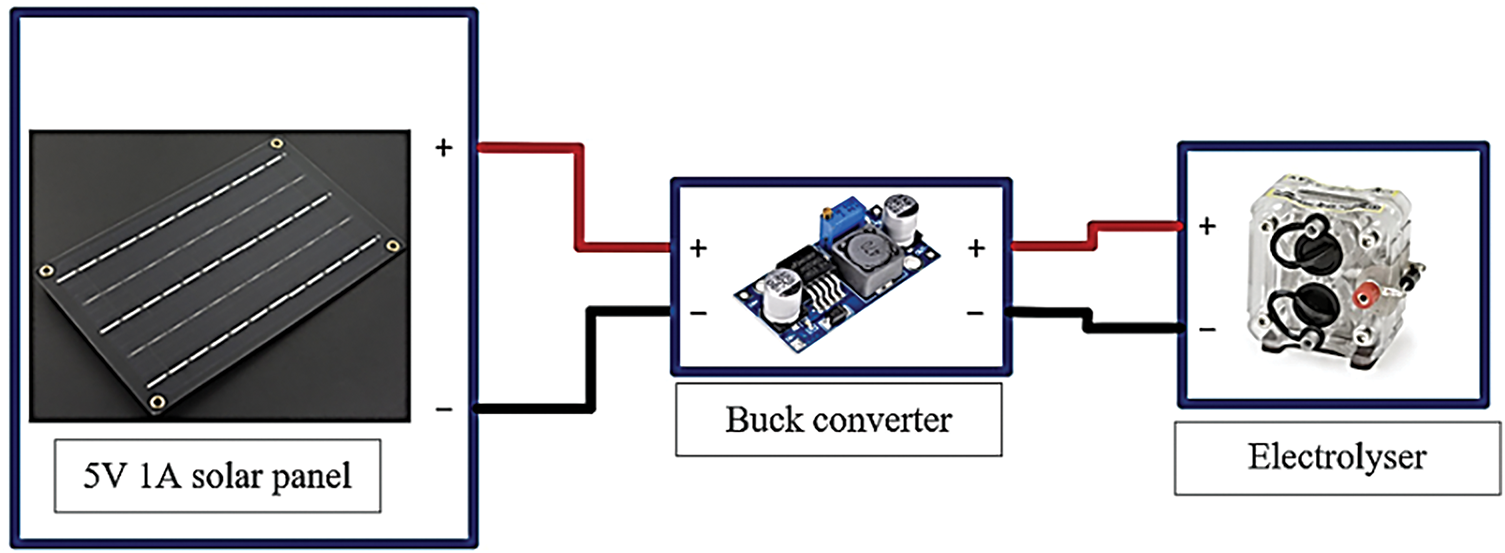
Figure 4: Front half segment
The connection of the rear half of the green hydrogen fuel cell car is illustrated in Fig. 5. The fuel cell acts as the car’s battery, supplying voltage to both the motor controller and the boost converter. Hydrogen and oxygen stored in the 30 mL storage tank flow into the fuel cell, where electricity is generated. The boost converter and motor controller are connected in parallel. The boost converter increases the voltage from the fuel cell (typically 3.7 V) to 5 V, which is the operating voltage required for the Arduino Nano. This voltage conversion is essential for the proper functioning of the microcontroller. The Arduino Nano sends signals to the motor controller to regulate the forward and backward movement of the N20 motor. Pins 7, 8, 9, and 10 on the Arduino Nano are connected to the four inputs on the motor controller. By configuring these pins in the code, the N20 motor can be controlled via the motor controller.
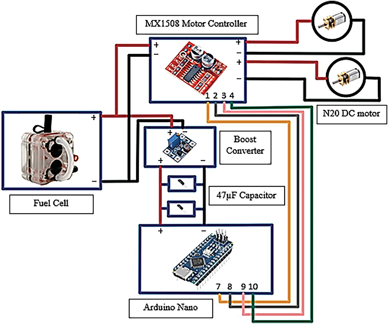
Figure 5: Back half segment
The complete connection structure of the solar hydrogen fuel cell car is illustrated in Figs. 4 and 5, which also demonstrate how the various components are integrated to form the overall design. To connect the front and rear sections of the vehicle, the 30 mL hydrogen and oxygen storage tanks are essential. This capacity was determined to be suitable for the small size of the green hydrogen fuel cell car, ensuring sufficient gas storage for efficient operation without compromising the vehicle’s compact design.
The two 47 µF capacitors are connected between the Nano microcontroller and the boost converter. Their primary function is to absorb voltage spikes that may occur during the microcontroller’s operation and to provide a stable voltage supply. This stabilization is crucial for maintaining the functionality and reliability of the electronic components, especially under varying loads.
It is important to note that when the solar panel is exposed to sunlight, the electrolyser continuously produces hydrogen and oxygen gas. This production continues as long as the solar panel remains exposed to sunlight. The generated hydrogen and oxygen gases are stored in two 30 mL storage tanks. When these gases are directed to the Quattro fuel cell, the cell generates electricity, which powers the load, including the motor controller and the Arduino Nano. Unlike conventional vehicles, the green hydrogen fuel cell car does not use a traditional battery; instead, the fuel cell acts as the battery to power the car. When the switch is turned on, the car begins to move and continues to do so until the hydrogen and oxygen gases in the 30 mL storage tanks are depleted, or the switch is turned off. Even if the solar panel is not exposed to sunlight or during cloudy conditions, the car will continue to operate as long as there is hydrogen and oxygen gas remaining in the storage tanks.
The design of the green hydrogen fuel cell car utilizes the Arduino programming language, as shown in Fig. 6, which depicts a flowchart of the complete program. This programming framework automates the car’s functions, enabling it to move forward, backward, and turn left or right as required. The programming flow can be summarized as follows: when the switch is turned on, the green hydrogen fuel cell car executes a specific sequence of movements. First, the car moves forward for 5 s and then pauses for 5 s. After this delay, the car turns left for 2.5 s and pauses again for 5 s. Next, the car moves backward for 5 s and pauses for another 5 s. Finally, the car turns left for 5 s and pauses once more for 5 s. If the switch remains on, the car will continuously repeat this sequence of movements. However, if the switch is turned off, the car will stop moving.
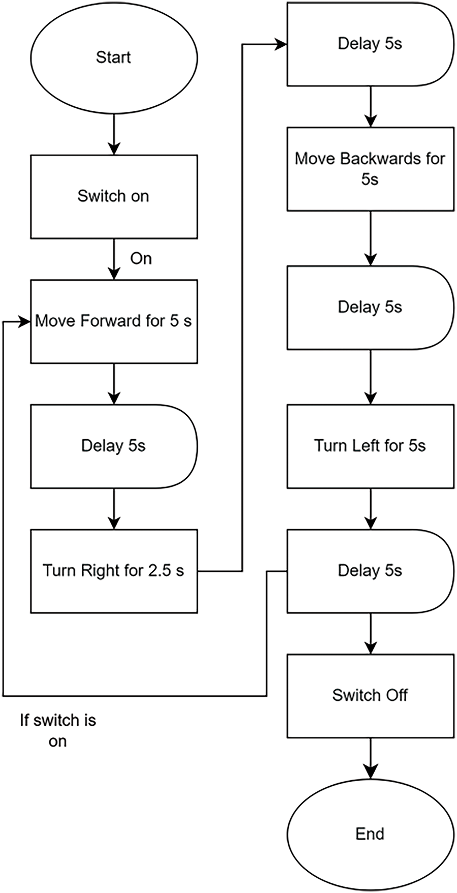
Figure 6: Programming for car movement
The results will demonstrate the production speed of the electrolyser powered by a DC power supply, evaluate its production rate when using a solar panel, and assess the consumption rates under varying load conditions.
4.1 Double Reversible Fuel Cell Testing
Referencing Table 3, the production speed of the electrolyser is measured when a DC power supply provides voltages of 3.6 and 3.7 V. The purpose of conducting this lab experiment is to determine the most optimized solar panel rating suitable for hydrogen and oxygen production. These specific voltage values were selected because they fall within the permissible operating range of the electrolyser, with 3.7 V being the upper limit. The data clearly shows that the production rate improves at the higher voltage of 3.7 V. This increase is attributed to the fact that a higher voltage allows more current to flow through the electrolyser, accelerating the production process.
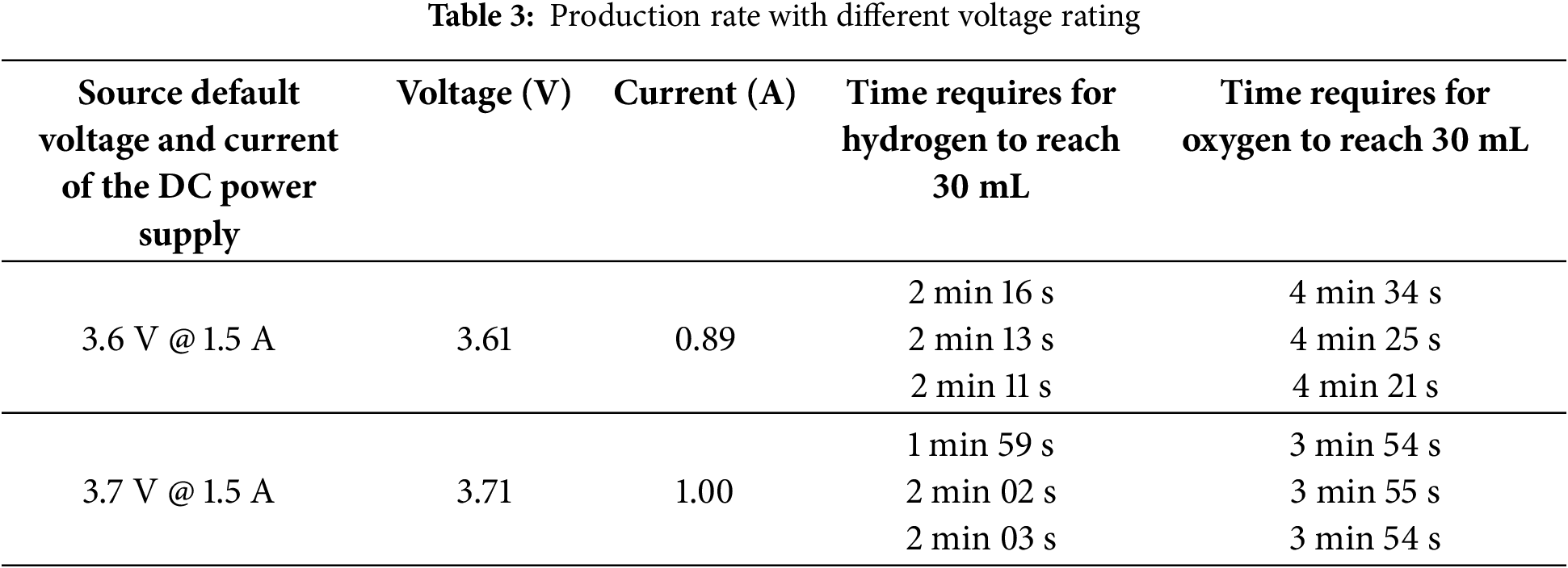
From Table 3, it can be observed that the default current value is 1.5 A; however, there is a significant drop to 0.89 and 1.00 A. This decrease is due to the resistance encountered when passing through the jumper wire while connecting to the double reversible fuel cell. This indicates that the resistance of the cable affects the output current of both the solar panel and the double reversible fuel cell. However, this effect is minimal and acceptable. By increasing the voltage of the DC power supply by 0.1 V, the current rises from 0.89 to 1.00 A. This increase in current enhances the production speed of hydrogen and oxygen. Therefore, to achieve a higher production rate, the voltage of the solar panel should be adjusted to allow more current to pass through the double reversible fuel cell. Based on lab testing, the recommended solar panel for the car should have a minimum voltage of 3.7 V and be capable of supplying at least 1 A.
However, it is challenging to source a solar panel that delivers exactly 3.7 V. To address this, a buck converter is used to step down the voltage from a selected solar panel output of 5 V to the required 3.7 V for the electrolyser. The electrolyser is designed to handle a maximum permissible current of 1.5 A; however, the chosen solar panel supplies only 1 A. Therefore, the monocrystalline solar panel (FIT0601) was selected due to its suitable size and weight, making it an optimal choice for integration into the solar hydrogen fuel cell car.
Additionally, it is important to note that the production of hydrogen was consistently twice that of oxygen. This means that while waiting for the oxygen volume to reach 30 mL, the hydrogen would have accumulated to 60 mL, reflecting the stoichiometric relationship in water electrolysis.
This section describes the integration of the chosen solar panel with the electrolyser to assess the production rate of the electrolyser on two different days. A detailed analysis of the data as shown in Table 4 shows that during the first part of the experiment, which required timing the amount of time it took for the hydrogen to build up to 30 mL, there were no disruptions caused by shadows blocking the solar panel. The constant time needed for the hydrogen to achieve the desired volume can be explained by this unbroken exposure to sunlight.
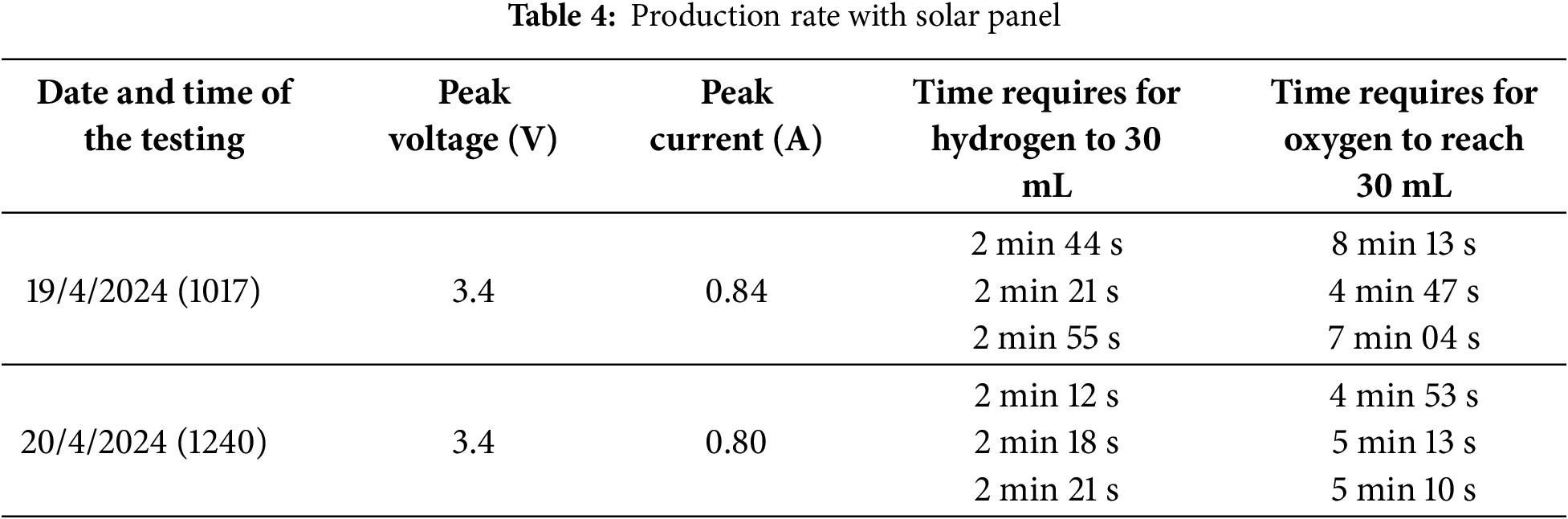
The data showed that the actual voltage recorded was only 3.4 V, even though the intended voltage supplied to the electrolyser was set at 3.7 V. This variance can be explained by the voltage drop in the circuit, but it has no impact on the overall conclusion of the research because the high current of the solar panel was what essentially drove the output rate. It is acknowledged that the output rate of solar energy can vary throughout the day or under different weather conditions due to sunlight being an uncontrollable factor. This aligns with the discussion in Section 2.3, which highlights the limitations of solar energy in meeting production demands, as it is only available during daylight hours and is affected by shading and temperature fluctuations. However, the outcomes of the solar panel integration are quite satisfactory, indicating the system’s efficiency in using solar energy to produce hydrogen.
4.3 Consumption Rate with Different Load
In addition to laboratory trials with the solar panel and electrolyser, several tests were conducted to determine the Quattro fuel cell’s consumption rate under various load conditions. These studies aimed to gain a better understanding of how different loads affect the fuel cell’s performance and efficiency. As shown in Table 3, four distinct types of loads were selected for these tests, each representing a different operational scenario that the fuel cell might encounter. To ensure accuracy and consistency, each load was tested three times, with the current from each experiment carefully recorded and averaged as shown in Table 5.
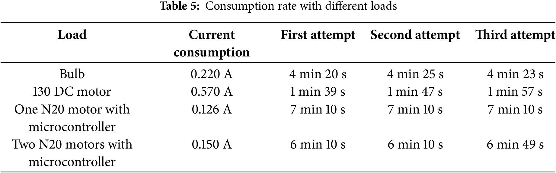
The 130 DC motor was the most demanding load among those examined, with the highest current consumption of 0.570 A, according to the data gathered from the lab studies. The 130 DC motor used all the available hydrogen in 1–2 min, making it the fastest to drain the hydrogen gas from the 30 mL storage tank because of its high current draw. This quick depletion demonstrates how increased power requirements drastically cut down on the fuel cell’s operating time. A bulb running at a far lower current of 0.220 A, on the other hand, had a significantly longer runtime, lasting roughly 4 min and 23 s before the hydrogen ran out. This suggests that the fuel cell can operate for longer periods of time with lower-current loads, underscoring the significance of load selection for efficiency. Additionally, tests were carried out with N20 DC motors connected to a microcontroller to investigate their effects on hydrogen consumption. When using a single N20 motor, the system drew the 0.126 A, allowing it to run for an astonishing 7 min and 10 s before the hydrogen ran out. On the other hand, running two N20 motors at the same time resulted in a current draw of 0.150 A, which was slightly greater than that of a single motor. This design allowed the motors to run for 6 min and 10 s, which was a significant reduction in runtime compared to utilizing only one motor. These findings highlight how current consumption affects the overall endurance and efficiency of the hydrogen fuel cell system.
These tests effectively show that combining the fuel cell, electrolyser, and solar panel into a single, integrated system is feasible. Analyzing the production rates revealed that the electrolyser produced 30 mL of hydrogen on average in 2 min and 28 s, while producing the 30 mL of oxygen took a little longer, on average 5 min and 48 s. The system’s effectiveness in transforming solar energy into useful hydrogen and oxygen gases is demonstrated by these timings. According to the consumption tests, it took the system 6 min and 10 s to use up all the hydrogen and oxygen in the 30 mL tank when two N20 DC motors were controlled by a microcontroller. Notably, the fuel cell’s ability to operate continuously depends on this balance between production and consumption rates. A prolonged consumption time indicates that the output rate of the electrolyser is adequate to meet the demands of the motors because the generation of hydrogen and oxygen continues while the gases are being consumed. This ongoing cycle of production and consumption highlights the possibility of creating a self-sufficient and effective system, where the combination of hydrogen fuel technology and renewable energy sources can sustain steady operation for long stretches of time. These results support the viability of powering devices with such a system and point to encouraging prospects for the advancement and improvement of green hydrogen fuel cell technology.
Fig. 7 is the prototype of the solar hydrogen fuel cell car, where the overall connection and components used were explained in the above sections.
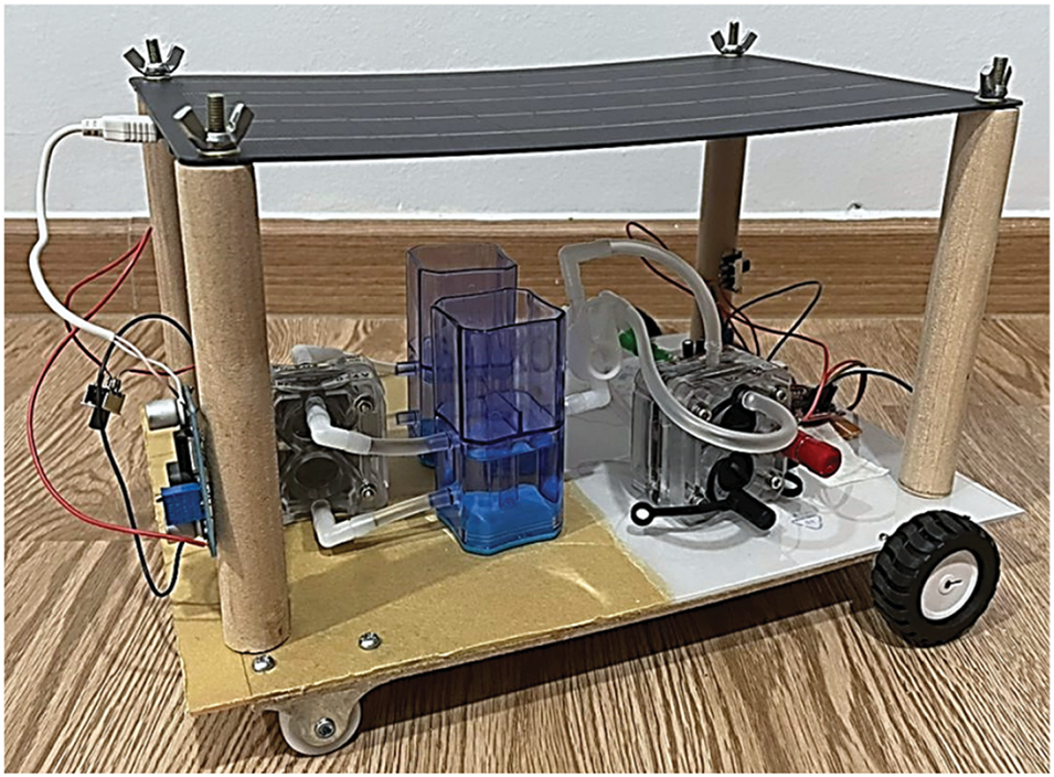
Figure 7: Prototype solar hydrogen fuel cell car
Fig. 8 illustrates the overall operational flow of the solar hydrogen fuel cell car. Initially, the solar panel provides power to the electrolyser, where electrolysis occurs to separate hydrogen and oxygen from distilled water. These gases are then directed into storage tanks before being supplied to the PEM fuel cell (PEMFC). As hydrogen and oxygen enter the PEMFC, electricity is generated to power the boost converter, microcontroller, and two motors. The car continues to operate until the hydrogen and oxygen are exhausted.
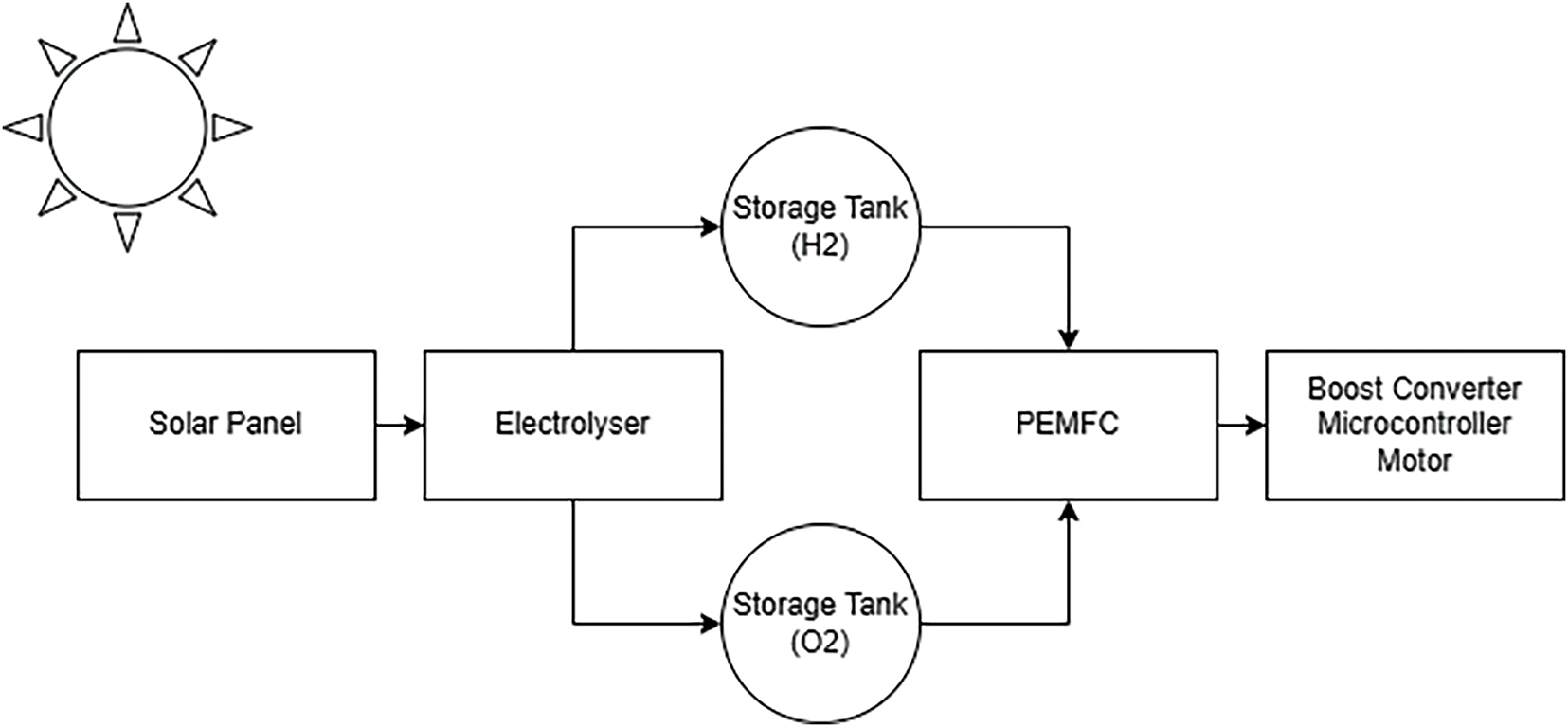
Figure 8: The operating flow of the solar hydrogen fuel cell car
The successful development of a green hydrogen fuel cell vehicle demonstrates the feasibility of integrating solar and hydrogen energy to achieve zero-emission transportation. The study yielded promising results, showing that current influences both the rate of hydrogen production in the electrolyser and the vehicle’s consumption rate. Testing revealed that using a microcontroller to operate two N20 motors increased current consumption by 17.4% compared to a single motor, leading to a significant reduction in runtime—approximately one minute less. Despite this, the hydrogen generation rate consistently met consumption demands, ensuring a stable supply of hydrogen and oxygen for the fuel cell. The combination of solar and hydrogen energy proved to be a viable power source, with the electrolyser’s output effectively sustaining the load, particularly when the solar panel was exposed to sunlight.
Since the consumption rate with two N20 DC motors is slower, hydrogen and oxygen depletion occur more gradually, allowing the electrolyser to maintain a balanced production-to-consumption ratio. This balance ensures a continuous supply of hydrogen and oxygen, enabling extended vehicle operation as long as sunlight is available. The successful lab experiments confirm that solar-hydrogen integration is a practical solution for powering a green hydrogen fuel cell car.
However, certain limitations were identified, including variations in solar panel output due to fluctuating sunlight conditions and mechanical challenges with the front tire and storage tank. These issues highlight areas for further improvement in the vehicle’s performance and reliability on a small scale. Future research should focus on large-scale validation under controlled conditions to assess the feasibility of scaling this technology for full-sized, zero-emission vehicles. Enhancing sunlight capture, improving mechanical components, and optimizing power supply efficiency—such as implementing switching modes for day and night operation—could significantly boost overall system performance. Additionally, integrating smartphone-based directional control could enhance usability and functionality.
This project underscores the potential of sustainable energy solutions, paving the way for a cleaner, more environmentally friendly future. With continued advancements in green automotive technology, this research could contribute to the development of a new generation of eco-friendly vehicles.
Acknowledgement: The authors would also like to thank and acknowledge the Swinburne University of Technology (Sarawak Campus).
Funding Statement: This research did not receive any specific grant or financial support from funding agencies in the public, commercial, or not-for-profit sectors. The authors conducted the study independently, and no external party influenced the study design, data collection, analysis, or decision to publish.
Author Contributions: Perry Yang Tchie Hunn: Conceptualization, Methodology, Writing—Original Draft, Data Curation, Formal Analysis, Visualization, Investigation, Writing—Editing. Hadi Nabipour Afrouzi: Review, Supervision, Project Administration. All authors reviewed the results and approved the final version of the manuscript.
Availability of Data and Materials: The authors confirm that the data used in this study is available on request.
Ethics Approval: Not applicable.
Conflicts of Interest: The authors declare no conflicts of interest to report regarding the present study.
Nomenclature
| PEMWE | Proton Exchange Membrane Water Electrolysis |
| PEMFC | Proton Exchange Membrane Fuel Cell |
| PEM | Proton Exchange Membrane |
| PEME | Proton Exchange Membrane Electrolyser |
| FC | Fuel Cell |
| DC | Direct Current |
| PV | Photovoltaic |
References
1. The History of Hydrogen [Internet]. altenergymag; 2009. [cited 2025 Feb 27]. Available from: https://www.altenergymag.com/article/2009/04/the-history-of-hydrogen/555/. [Google Scholar]
2. Adeyanju A, Agboola O. Fuel cells: an overview of its green value and readiness levels [Internet].ResearchGate; 2023. [cited 2025 Feb 27]. Available from: https://www.researchgate.net/publication/373726127_Fuel_Cells_An_Overview_of_Its_Green_Value_and_Readiness_Levels. [Google Scholar]
3. Li Y, Xu X, Bao D, Rasakhodzhaev B, Jobir A, Chang C, et al. Research on hydrogen production system technology based on photovoltaic-photothermal coupling electrolyzer. Energies. 2023;16(24):7982. doi:10.3390/en16247982. [Google Scholar] [CrossRef]
4. What is renewable energy? [Internet]. United Nations. [cited 2025 Feb 27]. Available from: https://www.un.org/en/climatechange/what-is-renewable-energy. [Google Scholar]
5. Local Renewable Energy Benefits and Resources [Internet]. United States Environmental Protection Agency; 2023. [cited 2025 Feb 27]. Available from: https://www.epa.gov/statelocalenergy/local-renewable-energy-benefits-and-resources#:~:text=Benefits%20of%20Renewable%20Energy,-Environmental%20and%20economic&text=Generating%20energy%20that%20produces%20no,in%20manufacturing%2C%20installation%2C%20and%20more. [Google Scholar]
6. Abbasi T, Abbasi SA. Renewable’ hydrogen: prospects and challenges. Renew Sustain Energy Rev. 2011;15(6):3034–40. doi:10.1016/j.rser.2011.02.026. [Google Scholar] [CrossRef]
7. Reda B, Elzamar AA, AlFazzani S, Ezzat SM. Green hydrogen as a source of renewable energy: a step towards sustainability, an overview. Environ Dev Sustain. 2024 May 2. doi:10.1007/s10668-024-04892-z. [Google Scholar] [CrossRef]
8. 5 Reason Why Hydrogen is the Fuel of the Future [Internet]. FuelCellWorks; 2020. [cited 2025 Feb 27]. Available from: https://fuelcellsworks.com/news/5-reasons-why-hydrogen-is-the-fuel-of-the-future/. [Google Scholar]
9. Maka AOM, Mehmood M. Green hydrogen energy production: current status and potential. Clean Energy. 2024;8(2):1–7. doi:10.1093/ce/zkae012. [Google Scholar] [CrossRef]
10. Hassan Q, Azzawi IDJ, Sameen AZ, Salman HM. Hydrogen fuel cell vehicles: opportunities and challenges. Sustainability. 2023;15(15):11501. doi:10.3390/su151511501. [Google Scholar] [CrossRef]
11. Fuel Cell Basics [Internet]. U.S. Department of Energy. [cited 2025 Feb 27]. Available from: https://www.energy.gov/eere/fuelcells/fuel-cell-basics#:~:text=Fuel%20cells%20work%20like%20batteries,)%E2%80%94sandwiched%20around%20an%20electrolyte. [Google Scholar]
12. Soleimani A, Hosseini Dolatabadi SH, Heidari M, Pinnarelli A, Mehdizadeh Khorrami B, Luo Y, et al. Progress in hydrogen fuel cell vehicles and up-and-coming technologies for eco-friendly transportation: an international assessment. Multiscale Multidiscip Model Exp Des. 2024;7(4):3153–72. doi:10.1007/s41939-024-00482-8. [Google Scholar] [CrossRef]
13. Shiva Kumar S, Himabindu V. Hydrogen production by PEM water electrolysis—a review. Mater Sci Energy Technol. 2019;2(3):442–54. doi:10.1016/j.mset.2019.03.002. [Google Scholar] [CrossRef]
14. Arunachalam M, Han DS. Efficient solar-powered PEM electrolysis for sustainable hydrogen production: an integrated approach. Emergent Mater. 2024;7(4):1401–15. doi:10.1007/s42247-024-00697-y. [Google Scholar] [CrossRef]
15. Acar C, Dincer I. 3.1 Hydrogen production. In: Comprehensive energy systems. Elsevier; 2018. p. 1–40. doi:10.1016/B978-0-12-809597-3.00316-3. [Google Scholar] [CrossRef]
16. Shiva Kumar S, Lim H. An overview of water electrolysis technologies for green hydrogen production. Energy Rep. 2022;8(10):13793–813. doi:10.1016/j.egyr.2022.10.127. [Google Scholar] [CrossRef]
17. Naimi Y, Antar A. Hydrogen generation by water electrolysis. In: Advances in hydrogen generation technologies. InTech; 2018. doi:10.5772/intechopen.75533. [Google Scholar] [CrossRef]
18. Kamran M, Fazal MR. Renewable energy conversion systems [Internet]. Elsevier Science; 2021. doi:10.1016/C2019-0-04294-4. [Google Scholar] [CrossRef]
19. Weber AZ, Balasubramanian S, Das PK. Proton exchange membrane fuel cells. In: Advances in chemical engineering [Internet]; 2012. p. 65–144. doi:10.1016/B978-0-12-386874-9.00002-3. [Google Scholar] [CrossRef]
20. Tellez-Cruz MM, Escorihuela J, Solorza-Feria O, Compan V. Proton exchange membrane fuel cells (PEMFCsadvances and challenges. Polymers. 2021;13(18):3064. doi:10.3390/polym13183064. [Google Scholar] [PubMed] [CrossRef]
21. Mekhilef S, Saidur R, Safari A. Comparative study of different fuel cell technologies. Renew Sustain Energy Rev. 2012;16(1):981–9. doi:10.1016/j.rser.2011.09.020. [Google Scholar] [CrossRef]
22. Benhala B, Marghani A, Chater EA, Bouganssa I, Sefiani N, Elakkary A, et al. Hydrogen production and applications: a review. E3S Web Conf. 2023;469(17):00088. doi:10.1051/e3sconf/202346900088. [Google Scholar] [CrossRef]
23. Dawood F, Anda M, Shafiullah GM. Hydrogen production for energy: an overview. Int J Hydrog Energy. 2020;45(7):3847–69. doi:10.1016/j.ijhydene.2019.12.059. [Google Scholar] [CrossRef]
24. Khan MMK, Azad AK, Oo AMT. Hydrogen energy conversion and management. Elsevier; 2023. doi:10.1016/C2021-0-02785-3. [Google Scholar] [CrossRef]
25. Tenba RS. Hydrogen fuel cell integration: automotive, residential power generation & portable devices. Int J Multidiscip Res. 2023;5(6). [Google Scholar]
26. Operating instructions. H-Tech Education; 2019. [cited 2025 Feb 27]. Available from: https://www.fuelcellstore.com/manuals/r104-double-reversible-fuel-cell.pdf [Google Scholar]
27. Nguyen VN, Blum L. Reversible fuel cells. In: Compendium of hydrogen energy [Internet]. Woodhead Publishing; 2016. p. 115–45. doi:10.1016/B978-1-78242-363-2.00006-3. [Google Scholar] [CrossRef]
Cite This Article
 Copyright © 2025 The Author(s). Published by Tech Science Press.
This work is licensed under a Creative Commons Attribution 4.0 International License , which permits unrestricted use, distribution, and reproduction in any medium, provided the original work is properly cited.
 Downloads
 Citation Tools