
 Submit a Paper
 Propose a Special lssue
 Open Access
ARTICLE

Frequency Adaptive Grid Synchronization Detection Algorithm Based on SOGI
1 China Southern Power Grid Co., Ltd., Guangzhou, 510663, China
2 School of Energy and Electrical Engineering, Chang’an University, Xi’an, 710064, China
* Corresponding Author: Xianfeng Xu. Email:
Energy Engineering 2025, 122(6), 2291-2307. https://doi.org/10.32604/ee.2025.063302
Received 10 January 2025; Accepted 14 April 2025; Issue published 29 May 2025
 View Full Text
 Download PDF
Abstract
In response to the complex working conditions of the power grid caused by the high proportion of new energy access, which leads to insufficient output accuracy of the second-order generalized integrator (SOGI) phase-locked loop, this article proposes an improved frequency adaptive phase-locked loop structure for SOGI. Firstly, an amplitude compensation branch is introduced to compensate for the SOGI tracking fundamental frequency signal, ensuring the accuracy of the SOGI output orthogonal signal under frequency fluctuation conditions. Secondly, by cascading two adaptive SOGI modules, the suppression capability of low-order harmonics and Direct Current (DC) components has been improved. Finally, the positive and negative sequence separation method of orthogonal signals is introduced to eliminate the influence of unbalanced components on the phase-locked loop. The comparative experiment with the classic SOGI-PLL method shows that the proposed phase-locked loop structure effectively improves the accuracy of power grid synchronization detection under complex working conditions such as harmonic components, unbalanced components, and frequency fluctuations. It can complete frequency detection within 1.5 power frequency cycles, and the detected fundamental frequency positive sequence voltage has a higher sinuosity and harmonic distortion rate within 0.5%.Keywords
With the expansion of renewable energy, the application of grid-connected inverters in the power system continues to increase [1]. As a key interface connecting distributed power sources and the power grid, precise control of the injected current into the grid can achieve grid synchronization support and power quality management, ensuring the stability and safety of the power system [2–5]. The implementation of high-quality synchronous grid-current injection for grid-connected inverters requires proper grid synchronization algorithms [6].
The existing grid synchronization algorithms are mainly based on PLL technology, which can effectively track changes in grid voltage [7,8]. However, due to the intermittency of renewable energy and the nonlinearity of power electronic devices, different operating conditions such as unbalanced components, harmonic distortion, and frequency fluctuations occur in the system [9,10]. Therefore, it is crucial to improve the steady-state accuracy and dynamic response performance of PLL under different operating conditions.
In order to improve performance under complex power grid conditions, researchers have proposed improvement measures applicable to different working conditions by enhancing the filtering ability of phase-locked loops, mainly including loop filtering and pre-filtering methods [11,12]. The loop filter will affect the adjustment of PLL parameters, resulting in poor stability and tracking speed [13], while the pre-filter faces the filtering problem of multiphase grid voltage [14]. Integrating delay filtering methods such as Moving Average Filter (MAF) and Delay Single Cancellation (DSC) in Synchronous Rotating Frame-PLL (SRF-PLL) [15–17] can be applied to pre-filtering and loop filtering, effectively reducing the impact of specific frequency grid harmonics and achieving better filtering capabilities, thereby obtaining more accurate grid voltage synchronization signals. In terms of frequency adaptive detection, by concatenating multiple filters with the same parameters and increasing the width of the notch frequency band, it is possible to achieve adaptive detection of small frequency fluctuations [18]; There are also studies that use negative feedback to compensate for amplitude and phase angle errors, achieving wideband frequency adaptive detection [19]. However, the above two filtering methods are cumbersome in parameter design for complex harmonic signals, and when the frequency of power grid harmonics changes, the overall filtering structure needs to be redesigned, which is not universal. A notch filter (NF) similar to delay filtering can also selectively eliminate harmonic components [20], however, multiple NFs need to be cascaded in the PLL control loop, which increases the complexity of the PLL structure. Reference [21] proposed a structurally simple complex coefficient filtering phase-locked loop (CCF-PLL), which can achieve fast and accurate phase locking under unbalanced power grid voltage. However, the bandpass filtering performance limits the filtering effect, and the detection phase and frequency errors are relatively large.
The classic generalized integrator structure is widely used in pre-filtering, and its output orthogonal signal features can stably extract the positive and negative sequence components of the grid voltage, with good steady-state and transient performance. Reference [22] proposed a Sine amplitude integrator phase-locked loop (SAI-PLL), which uses two cross decoupled sine amplitude integrators to separate the positive and negative sequence components of the grid voltage. It also introduces a frequency adaptive unit, which can effectively detect the frequency and phase of the grid voltage when the three-phase voltage is unbalanced and there is a frequency step. Reference [23] proposes a phase-locked loop structure based on the SOGI, which has better filtering performance than SAI-PLL, but cannot eliminate the influence of DC components. Reference [24] proposes adding a filtering element to the second-order generalized integrator to form a third-order generalized integrator phase-locked loop (TOGI-PLL), which can further suppress the influence of DC components. However, due to the limitation of the frequency selection characteristics of the generalized integrator, the filtering effect on low-order harmonics is poor, and the low-order harmonic content in the power grid is often high, which has a significant impact on the accuracy of the phase-locked loop. And frequency fluctuations will cause errors in the output fundamental wave. In addition, researchers have combined the different filters mentioned above to leverage their optimal characteristics and applied them separately to in-loop filtering and pre-filtering, achieving a hybrid filtering phase-locked loop structure [25]. However, the design structure of hybrid filtering is relatively complex and may also have significant delays.
This article optimizes the SOGI structure in terms of frequency adaptation and filtering, based on its superior filtering and output performance. By analyzing the characteristics of SOGI output under frequency fluctuations, an amplitude compensation branch was designed to eliminate errors, ensuring the stability and accuracy of tracking the fundamental frequency grid signal under different frequency conditions; Aiming at the problem of SOGI lacking DC component and insufficient filtering ability, a cascaded structure of two adaptive SOGI was designed for optimization, and the resulting cascaded structure has better filtering ability and DC bias suppression ability; Furthermore, for the orthogonal signals output by SOGI, a positive-negative sequence separation method is introduced to achieve the separation of positive and negative sequence voltages in unbalanced power grids. Finally, the optimized structure designed should be included in the PLL pre-filtering stage to achieve grid synchronization detection function. Through two experiments, it was verified that the designed phase-locked loop structure could stably detect power grid information under frequency fluctuations, harmonic disturbances, and unbalanced component disturbances. Compared with SOGI-PLL, the designed structure has higher accuracy and faster dynamic response speed.
2 SOGI Pre-Filter Phase-Locked Loop Structure
This section mainly discusses the structure of the phase-locked loop and the SOGI pre-filtering method.
The structure of the phase-locked loop with pre-filtering is shown in Fig. 1.
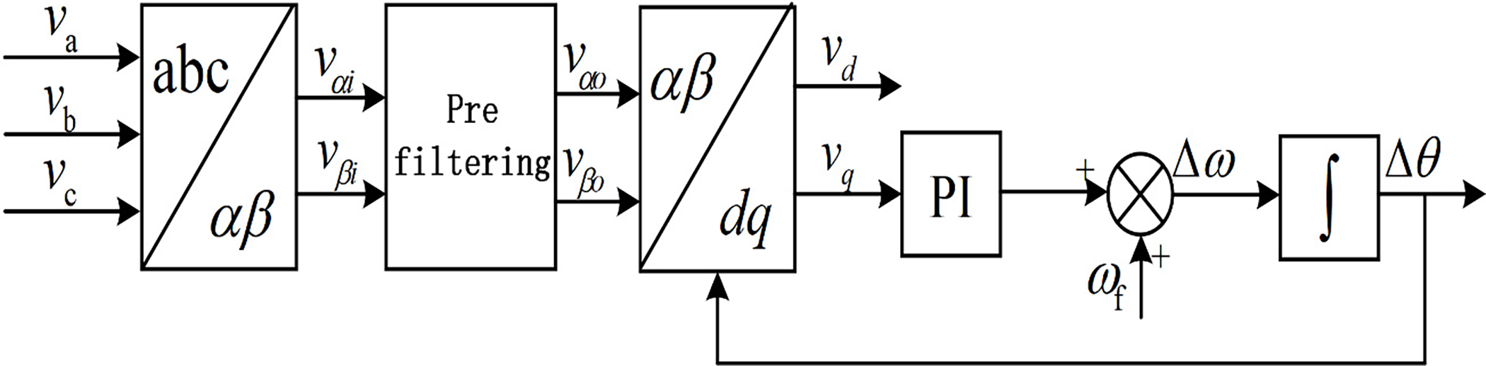
Figure 1: Structure diagram of SRF-PLL for pre-filtering
SRF-PLL converts the three-phase voltage signals (
By eliminating the disturbance components in the power grid through pre-filtering, the fundamental frequency orthogonal signals
Among them,
SOGI is a bandpass filter, which can track the fundamental signal and eliminate high-order harmonics in the pre-filtering stage. Its structure is shown in Fig. 2. In Fig. 2, vi is the input grid voltage, vo and qvo are the two output signals of SOGI, with equal amplitudes and a phase difference of 90°. k is the damping coefficient of SOGI, and
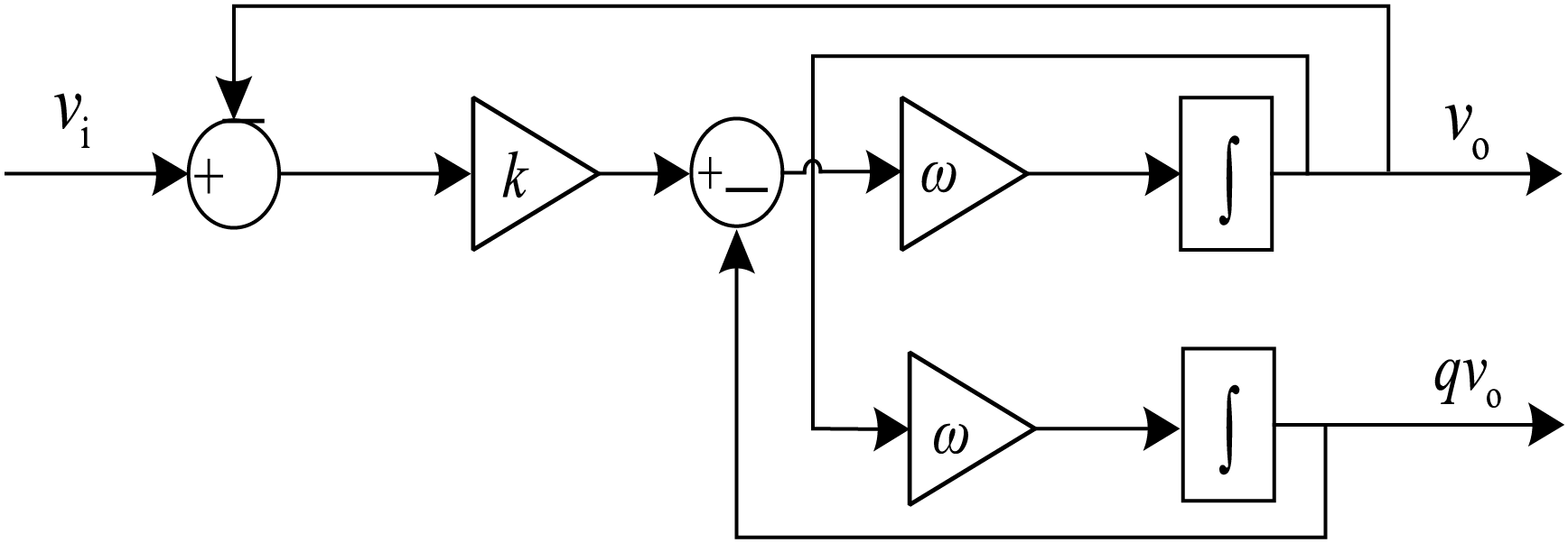
Figure 2: SOGI structure diagram
As shown in Fig. 2, the transfer function of SOGI [1,2]:
The value of coefficient k determines the dynamic response capability and filtering capability of SOGI. Fig. 3 shows the Bode plots for
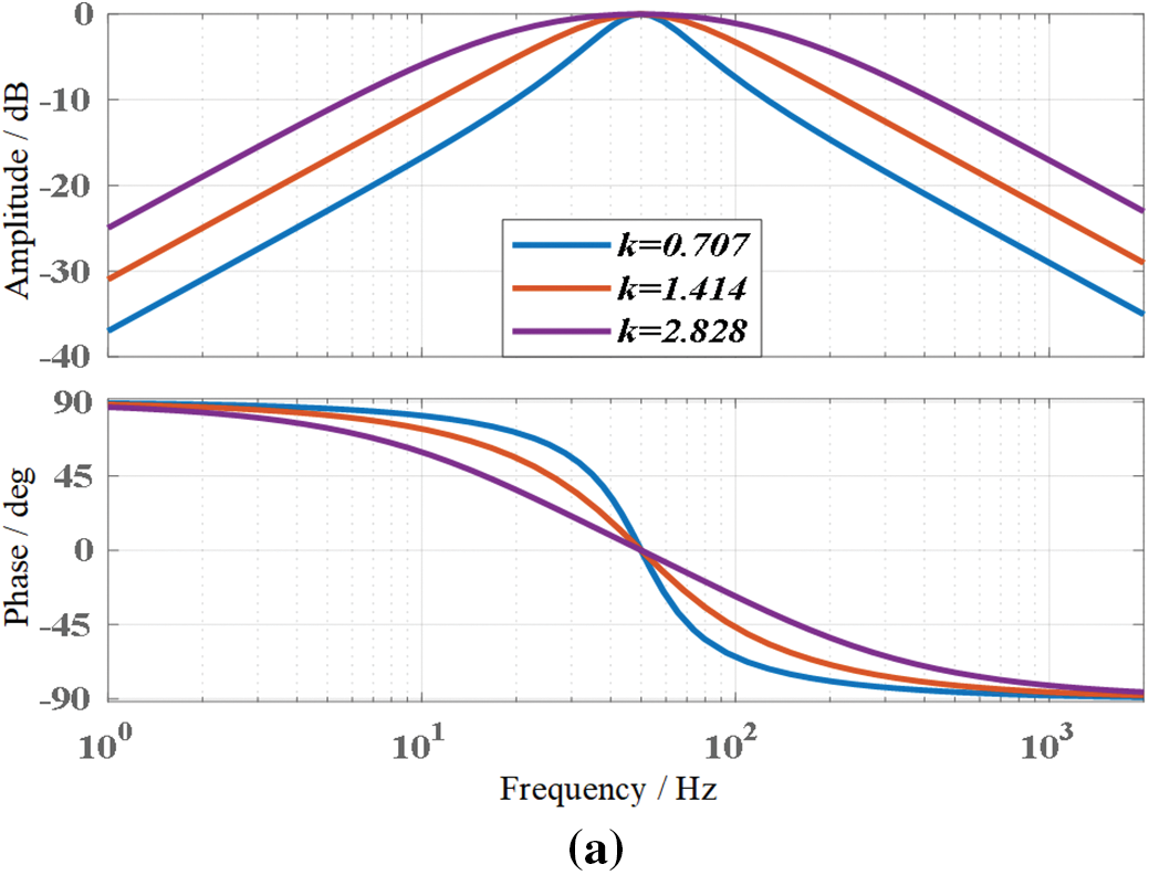
Figure 3: Bode plot of SOGI under different coefficients. (a) DSOGI(s) bode plot; (b) QSOGI(s) bode plot
From the Bode plot of SOGI, it can be seen that when the frequency fluctuates, the fundamental frequency grid voltage signal tracked by SOGI output will experience amplitude attenuation. And SOGI has weak filtering ability for low-order harmonics. When the frequency decreases, the frequency points of each harmonic shift to the left, which will further weaken the filtering ability of low-order and low-order harmonics. Ultimately, it will have an impact on the accuracy of grid synchronization detection.
3 Improved SOGI Pre-Filter Phase-Locked Loop Structure
This section is based on the classic SOGI and designs suitable structures in terms of frequency adaptation and filtering capabilities.
3.1 Optimization of SOGI Frequency Adaptation
Assuming the grid voltage
In Eqs. (5) and (6), parameters A and
When the system is in steady state, the voltage of the power grid on the
Convert the above four equations into input and output representations:
If
According to Eqs. (16)–(19), frequency fluctuations will cause error terms in the output of the original SOGI, and the error term can be calculated from the orthogonal signal corresponding to that channel. Therefore, based on the orthogonal signal output by SOGI, a frequency adaptive amplitude compensation branch is constructed, and the corresponding frequency adaptive SOGI (FSOGI) structure is shown in Fig. 4.
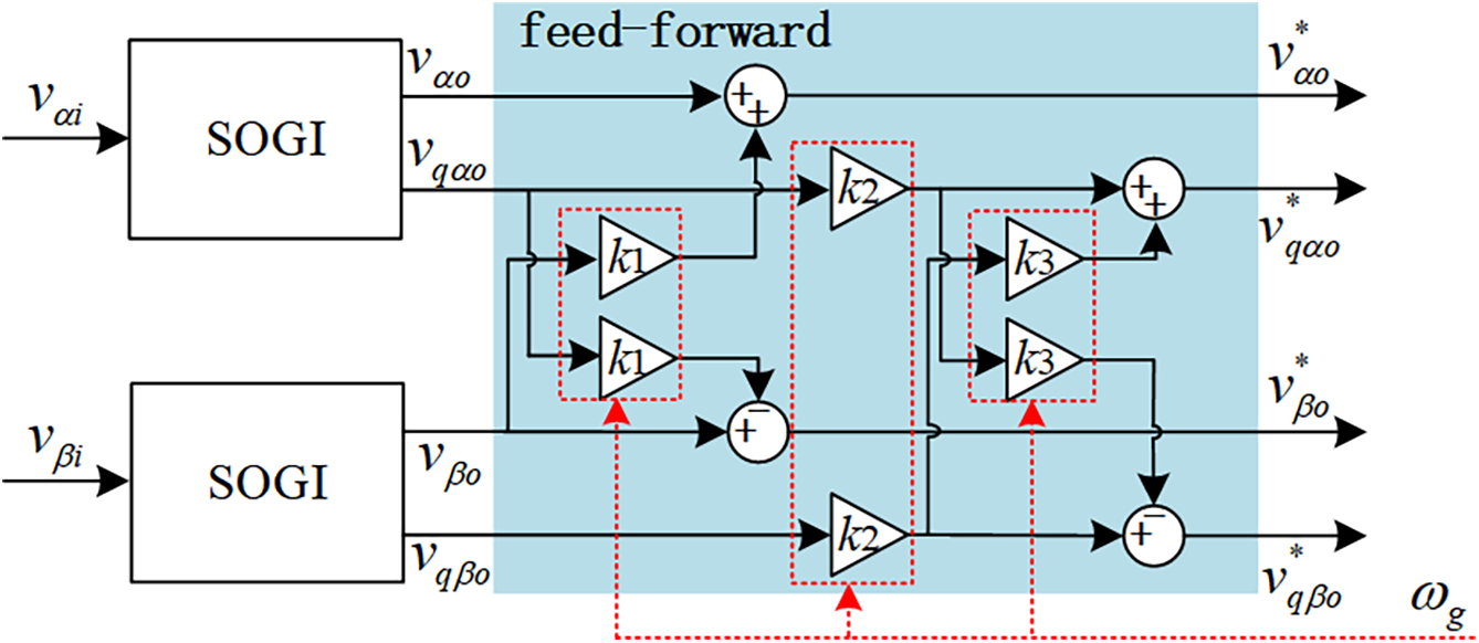
Figure 4: FSOGI frequency adaptive feedforward compensation structure
In Fig. 4, k1, k2 and k3 correspond to three error coefficients, which are obtained through digital operations using fixed
3.2 Optimization of SOGI Filtering Performance
In order to optimize the problem that SOGI cannot eliminate DC components and has weak filtering ability, two FSOGIs are metered to form Frequency Cascade SOGI (FCSOGI), and the channel with equal amplitude and phase angle output from FSOGI is used as the input of the next stage FSOGI. The overall structure is shown in Fig. 5.
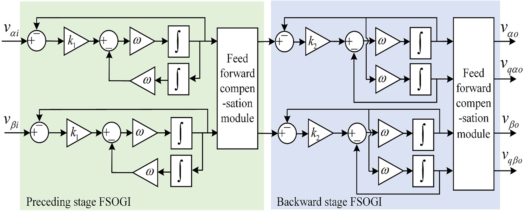
Figure 5: FCSOGI structure diagram
The constructed FCSOGI has two adjustable proportional parameters, which can provide a wider range of adjustments for filtering ability and dynamic response-ability. By adjusting and selecting the dynamic response and filtering capabilities of FCSOGI, the Bode plots under different parameters are shown in Fig. 6.
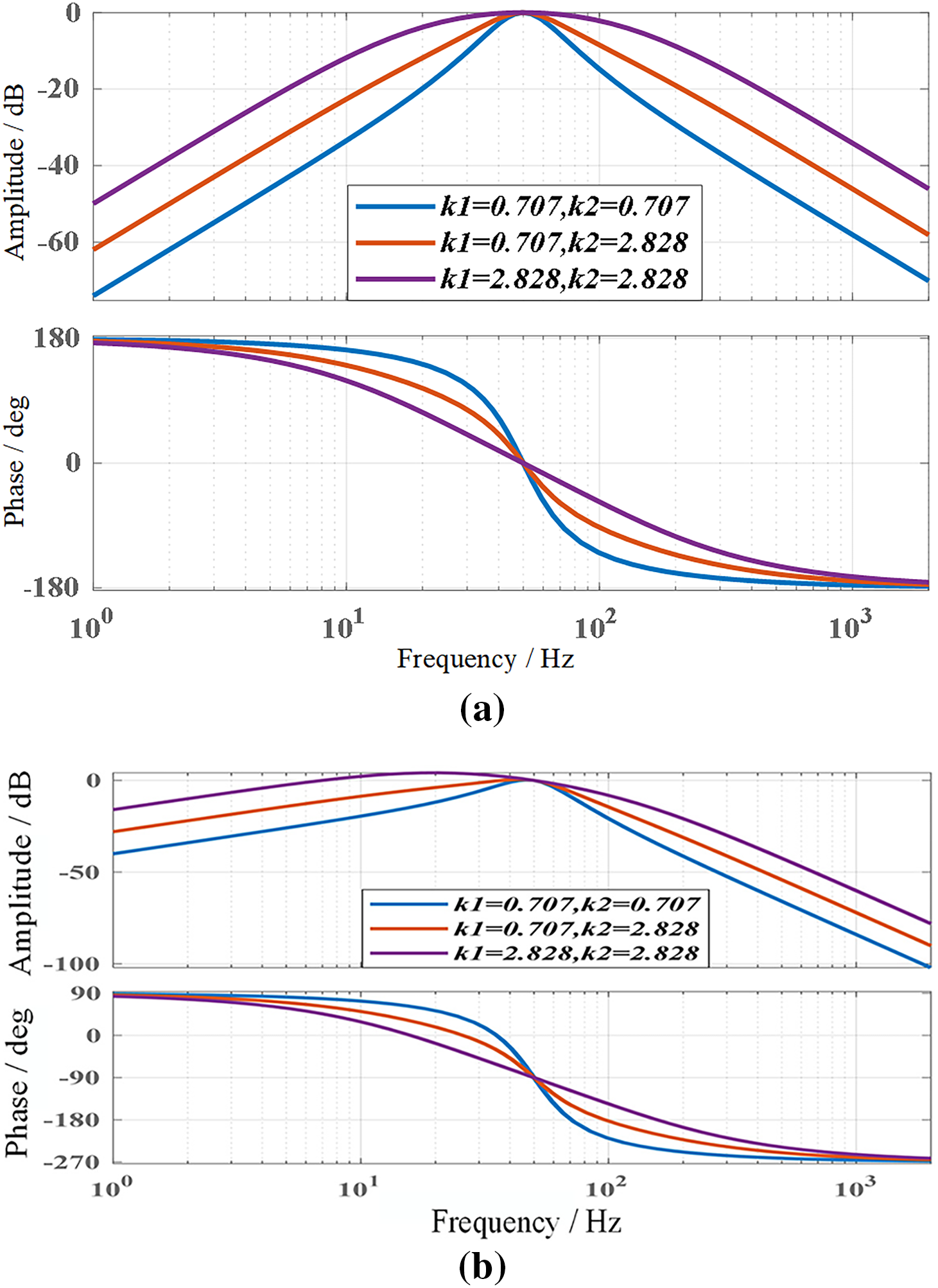
Figure 6: Bode plot of FCSOGI under different coefficients. (a) DFCSOGI(s) bode plot; (b) QFCSOGI(s) bode plot
From Fig. 6, it can be seen that as
Fig. 7 compares the Bode plots of the transfer functions of SOGI and FCSOGI under approximate dynamic response time. Among them, the dynamic response curve is shown in Fig. 8, with a time of about 30 ms. From Fig. 7, it can be seen that FCSOGI has stronger filtering ability at harmonics of various frequencies, and improves the suppression defect of the original QSOGI(s) that cannot suppress DC signals. FCSOGI has a filtering ability of over 90% for harmonics of 5 or more. Compared with SOGI, FCSOGI keeping a good dynamic response time, and the filtering ability of each harmonic is improved, thereby better eliminating the impact of low-order harmonics on the accuracy of power grid signal synchronization detection.
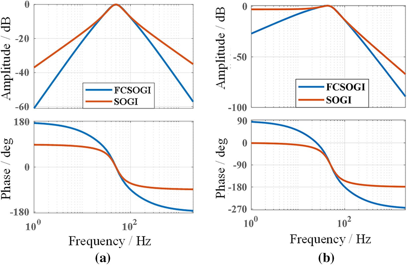
Figure 7: FCSOGI and SOGI Bode plots. (a) D(s); (b) Q(s)
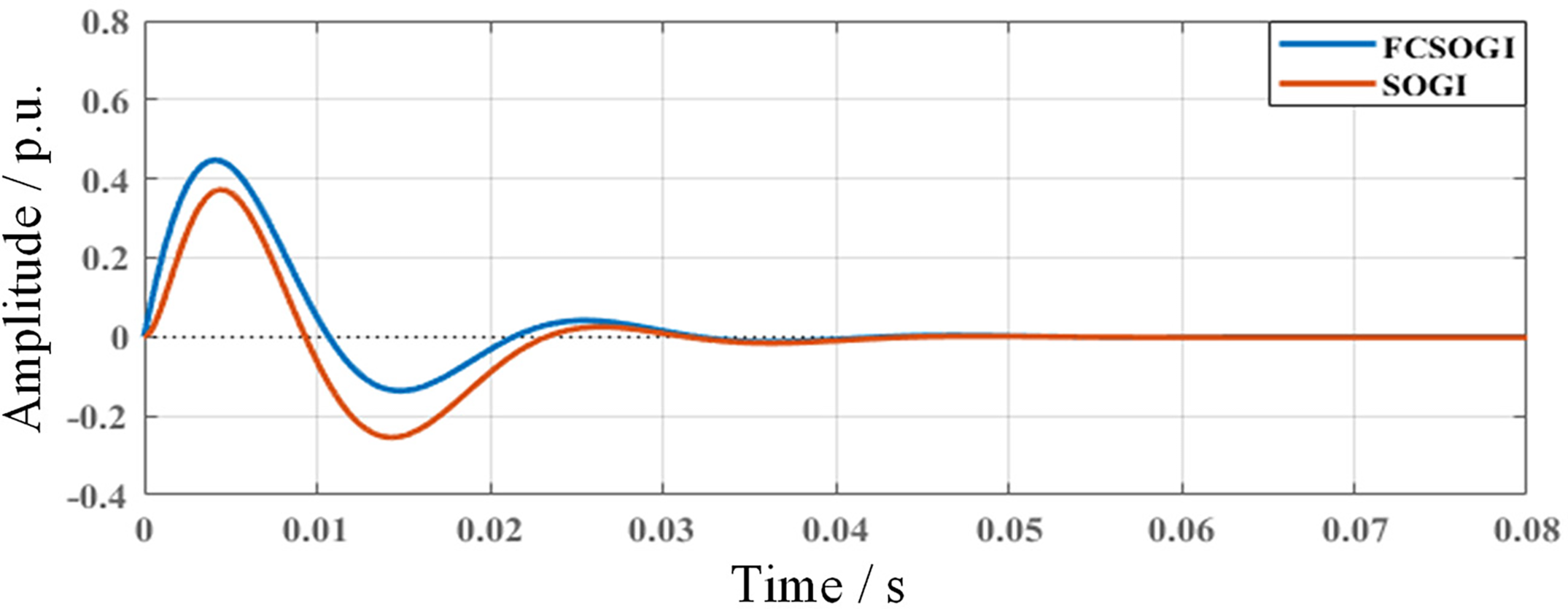
Figure 8: FCSOGI and SOGI step response diagram
Table 1 compares the distortion rates of signals
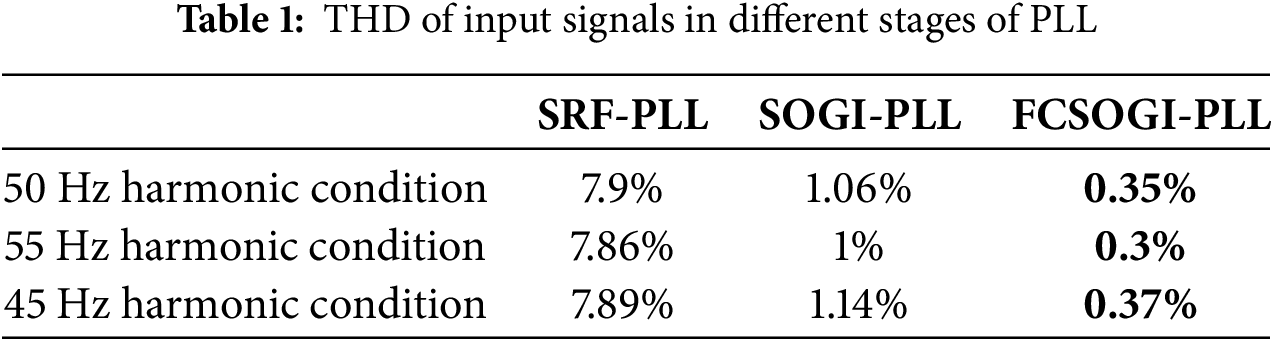
From Table 1, it can be seen that the proposed FCSOGI-PLL method can ensure high-quality signals under different frequency conditions, thereby avoiding interference with the phase-locked loop, and the filtering ability is relatively stable. Meanwhile, using the SOGI-PLL method, the amplitude error of the output signal vd under frequency fluctuation conditions is ±1.5%, while the FCSOGI-PLL error proposed in this paper is only ±0.4%. Therefore, the proposed FCSOGI-PLL method can better filter and output orthogonal signals, and ensure the accuracy of amplitude and phase angle detection under frequency fluctuations.
In order to eliminate the influence of the second harmonic component generated by the Park transformation of the unbalanced voltage component in the power grid on the two-phase signals of the phase-locked loop vd and vq. In the
Based on the above analysis, the overall formed FCSOGI-PLL phase-locked loop is shown in Fig. 9. The phase-locked loop can first suppress the disturbance of DC components and complex harmonic components through a pre-filtering link, and at the same time compensate for orthogonal output based on the grid frequency. The extraction of positive and negative sequence components of unbalanced components can be achieved through the positive and negative sequence separation process. Finally, the real-time phase, frequency, and amplitude of the power grid are calculated using a phase-locked loop.
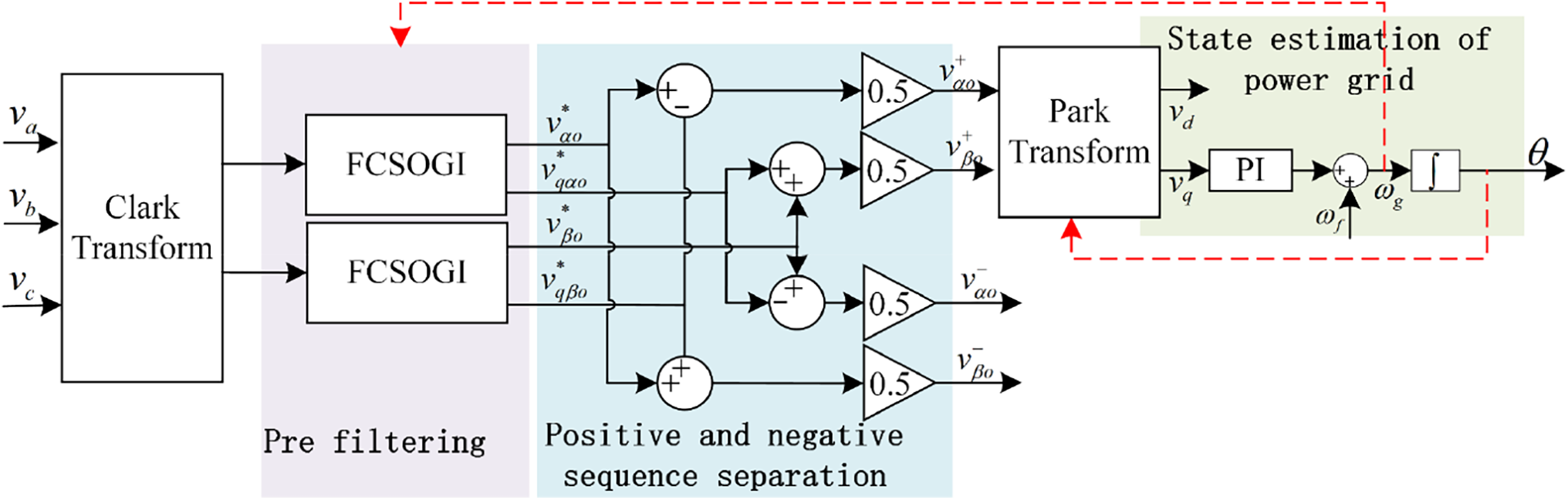
Figure 9: Structure of FCSOGI-PLL phase locked loop
In order to verify the effectiveness of the designed phase-locked loop structure, two experiments were conducted. Firstly, the FSOGI a frequency adaptive grid synchronization detection capability designed in Section 3.1 was validated under frequency fluctuation conditions to verify the rationality of the amplitude compensation branch designed. Secondly, verify the grid synchronization detection capability of the FCSOGI designed in Section 3.2 under complex grid conditions to validate the rationality of the designed series FSOGI structure. In the experiment, the main circuit of the three-phase power grid system was imported into the real-time simulator through the StarSim HIL software of the upper computer, and the phase-locked loop control structure was imported into the controller through the RCP software of the upper computer. The sampling frequency is 15 kHz, and the two are transmitted through wiring terminals. The experimental platform is shown in Fig. 10.
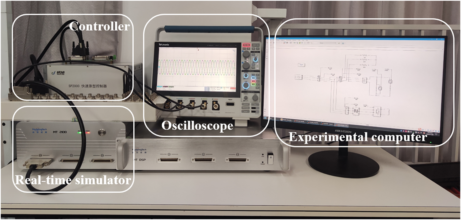
Figure 10: Experimental platform
Experiment 1: Design two power grid operating conditions, and compare the grid synchronization detection capabilities of FSOGI-PLL and SOGI-PLL phase-locked loops. The first condition is to increase the frequency by 5 Hz, while the second condition is to decrease the frequency by 5 Hz. Figs. 11–13 respectively show the actual power grid voltage waveform, the phase-locked loop detection frequency, the positive sequence voltage waveform detected by the phase-locked loop (phase A), and the detection of positive sequence voltage error.
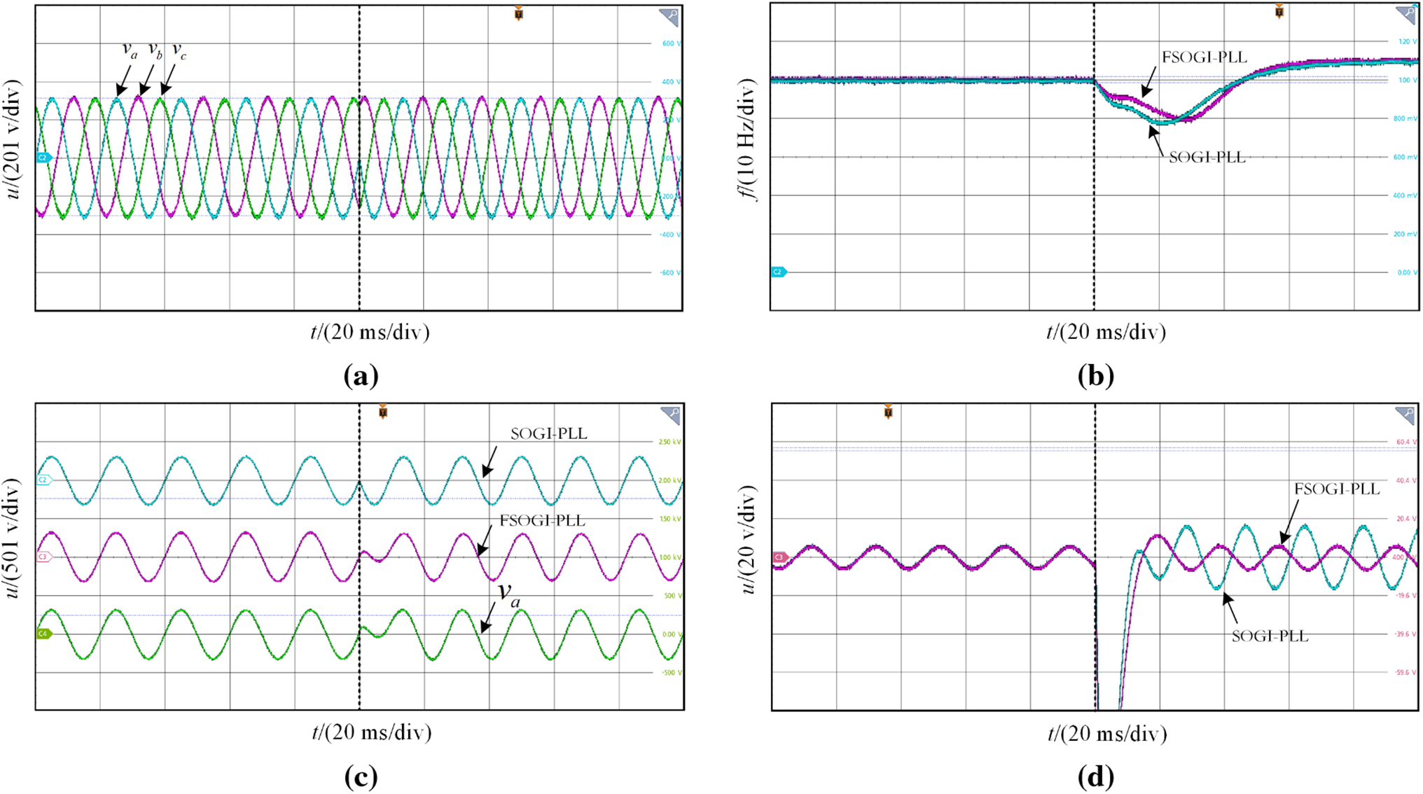
Figure 11: Condition one: Frequency increase by 5 Hz. (a) Grid voltage waveform; (b) PLL detection frequency; (c) Detection positive sequence; (d) Voltage detection error
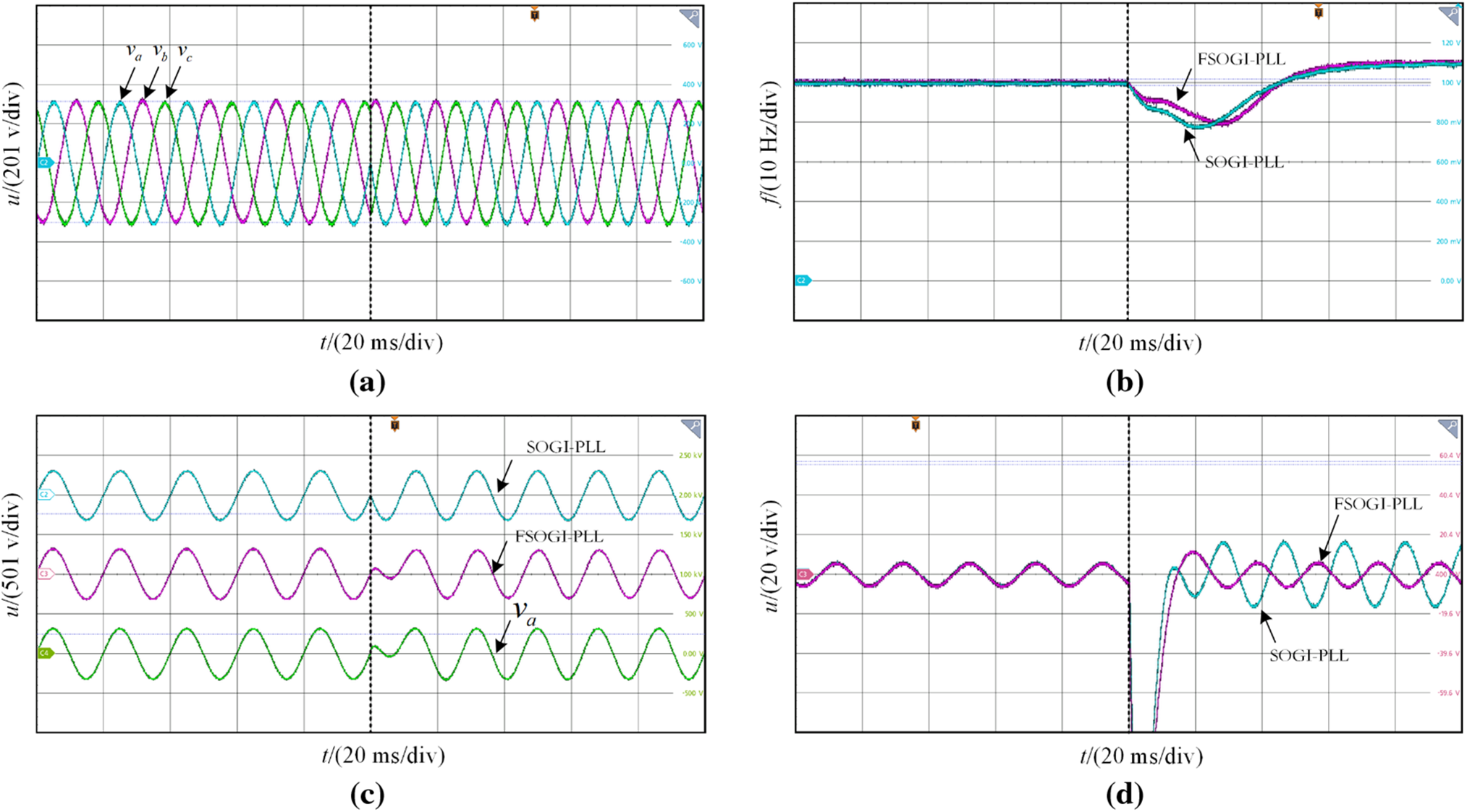
Figure 12: Condition two: Frequency decrease by 5 Hz. (a) Grid voltage waveform; (b) PLL detection frequency; (c) Detection positive sequence; (d) Voltage detection Error
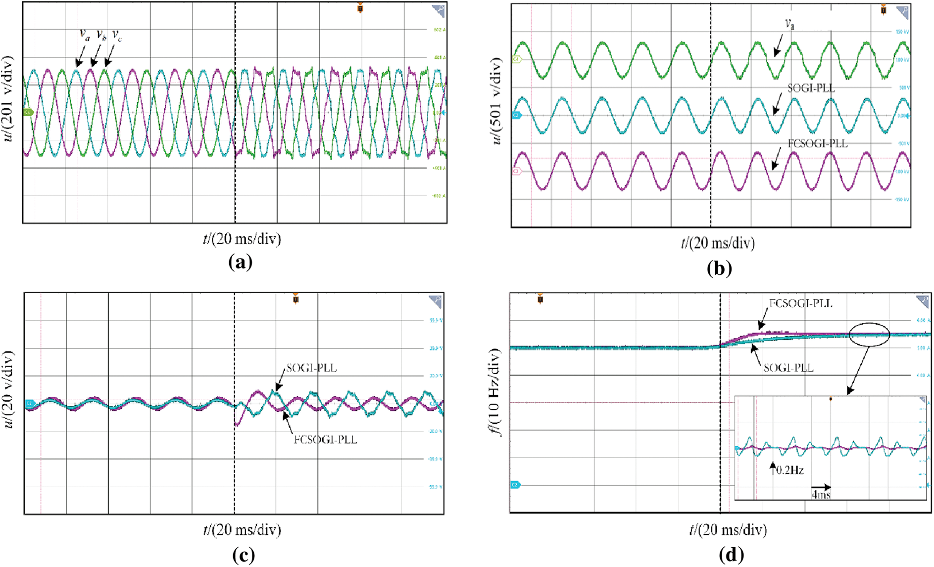
Figure 13: Grid synchronization detection condition one. (a) Grid voltage waveform; (b) Detection positive sequence; (c) Voltage detection error; (d) PLL detection frequency
From Figs. 11 and 12, it can be seen that under the conditions of increasing and decreasing frequency, FSOGI-PLL has a faster frequency detection speed compared to SOGI-PLL. This is mainly because the designed amplitude compensation branch has frequency adaptive adjustment ability for the fundamental frequency signal, which can track the fluctuations of the power grid frequency faster. From Figs. 11c and 12c, both phase-locked loops can detect the positive sequence voltage of the power grid. From Figs. 11c and 12c, FSOGI has a smaller error in detecting the positive sequence voltage of the power grid, and there is almost no additional error under frequency fluctuations. This further verifies that the designed amplitude compensation branch applied to SOGI can achieve higher precision grid synchronization detection under frequency fluctuation conditions.
Experiment 2: Design three power grid operating conditions, and compare the grid synchronization detection capabilities of FCSOGI-PLL and SOGI-PLL phase-locked loops, to verify the accuracy of the designed phase-locked loop in synchronous detection of power grids under complex conditions of harmonics, frequency fluctuations, and three-phase imbalance. The experimental conditions for the three working conditions are as follows:
Condition one: Inject 5% of the 5th and 7th harmonics into the system under ideal grid conditions; 2.5% of the 11th and 13th harmonics, and 1.5% of the 17th and 19th harmonics, while increasing the frequency by 5 Hz.
Condition two: Inject the same harmonics as Scenario 1 into the system under ideal grid conditions, while reducing the frequency by 5 Hz.
Condition three: Under ideal grid conditions, inject the same harmonics as Scenario 1 into the system, while reducing the frequency by 5 Hz and lowering the A-phase voltage and C-phase voltage.
Figs. 13–15 show the voltage waveforms of the power grid under three different operating conditions, the fundamental positive sequence voltage detected by the phase-locked loop (taking phase A as an example), the voltage error diagram, and the output frequency diagram of the phase-locked loop.
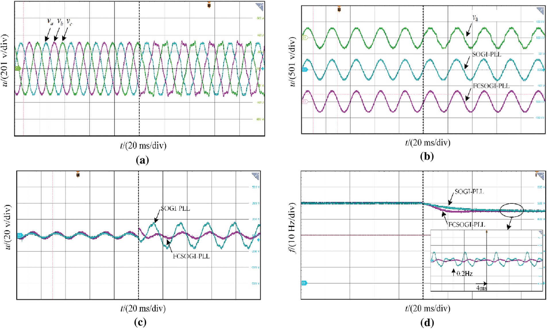
Figure 14: Grid synchronization detection condition two. (a) Grid voltage waveform; (b) Detection positive sequence; (c) Voltage detection error; (d) PLL detection frequency
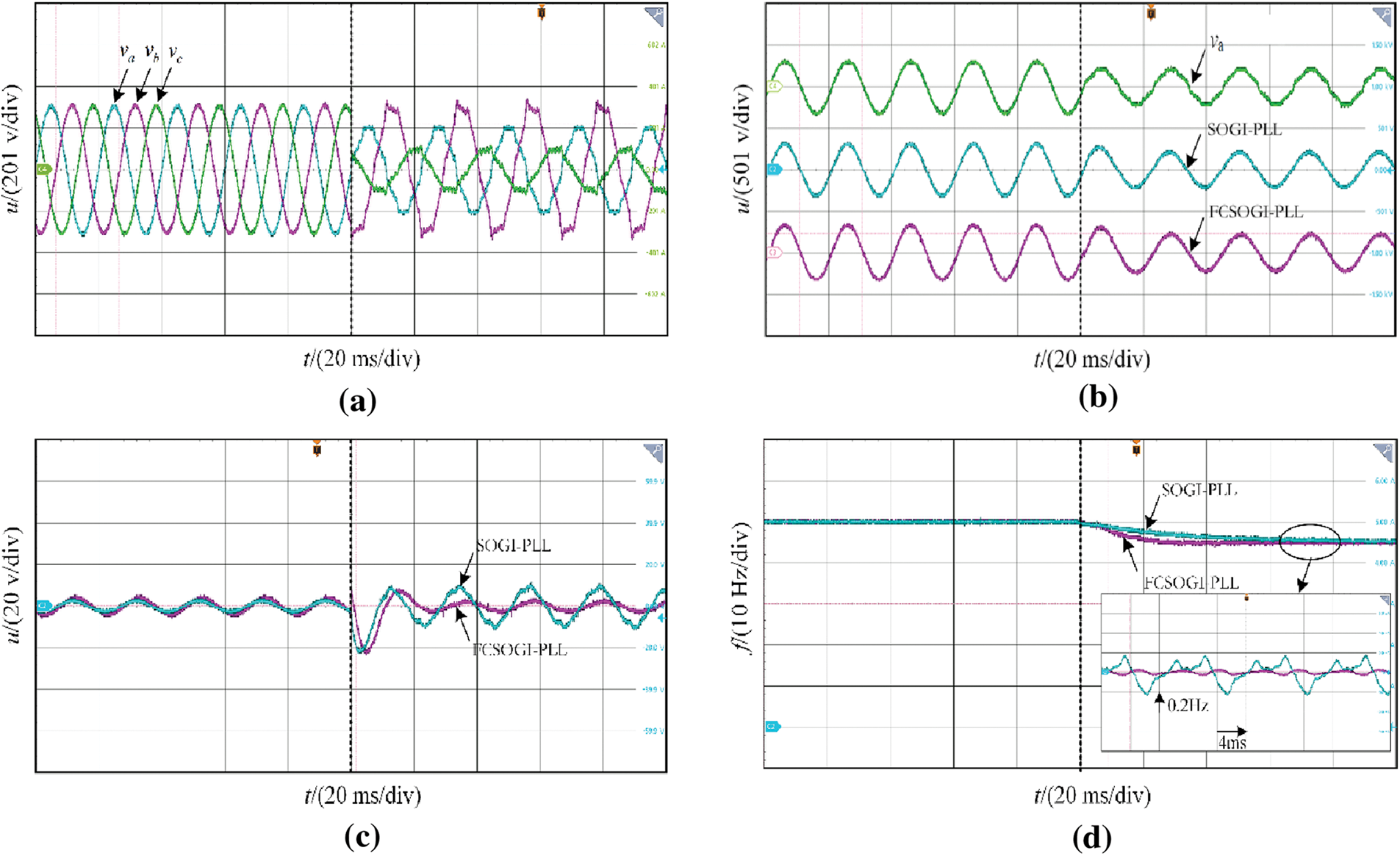
Figure 15: Grid synchronization detection condition three. (a) Grid voltage waveform; (b) Detection positive sequence; (c) Voltage detection error; (d) PLL detection frequency
Taking the A-phase voltage as an example, Figs. 13b, 14b, and 15b compare the actual voltage of the power grid with the positive sequence voltage detected by two types of phase-locked loops. It can be seen that the designed FCSOGI-PLL can better filter out harmonics in the power grid under different operating conditions, with a harmonic distortion rate maintained below 0.5%. The voltage distortion rate detected by the SOGI-PLL is around 1%, which verifies that the positive sequence fundamental frequency power grid voltage quality detected by the designed series structure is higher. Meanwhile, by introducing the positive and negative sequence separation modules, it can be seen that both phase-locked loops can stably detect the fundamental positive sequence voltage of the power grid under three-phase unbalanced conditions.
Figs. 13c, 14c, and 15c show the voltage errors detected under three operating conditions. It can be seen that due to frequency fluctuations, there is a significant error in tracking the fundamental frequency voltage of SOGI-PLL under fixed parameters, with voltage errors ranging from ±3% to ±5% at different frequencies. The designed FCSOGI-PLL has an amplitude compensation loop, which can ensure the detection accuracy of the fundamental frequency voltage at different frequencies. Under three different frequency variations, there is almost no additional error, and the voltage error is approximately the same as that under the original ideal power grid, and remains unchanged at ±1.2%. This error is the inherent error of the filter. It also verifies that it has better frequency adaptation capability while ensuring the quality of the detected fundamental frequency positive sequence voltage.
It can be seen from the detection frequency in Figs. 13d, 14d and 15d, both phase-locked loops can track the changes in system frequency. The output frequency dynamic response of SOGI-PLL is slow due to the fixed parameters, and the output frequency error is ±0.2 Hz due to the lack of filtering ability. Under different working conditions, FCSOGI-PLL can detect the power grid frequency stably in about 30 ms, and the accuracy of frequency detection is greatly improved, with an error of only ±0.02 Hz, which can meet the standard requirements of detection. It also verifies that the designed FCSOGI-PLL has better power grid synchronization detection capability.
In response to the problem of insufficient output accuracy of the original SOGI-PLL under complex power grid conditions, this paper designs an FCSOGI-PLL phase-locked loop structure. A feedforward amplitude compensation method was designed to compensate for the output orthogonal signal caused by frequency fluctuations, ensuring the accuracy of fundamental frequency voltage detection; In response to the insufficient filtering ability of SOGI, a two-stage series structure was designed to enhance the filtering ability and the suppression ability of DC components. The experimental results show that the FCSOGI-PLL designed for detecting the fundamental frequency positive sequence voltage of the power grid has higher quality, with a distortion rate of less than 0.5%, and the detected voltage error remains basically unchanged at different frequencies. The phase-locked loop detection system has higher frequency accuracy, with an error of only ±0.02 Hz under different operating conditions, and can achieve tracking within 1.5 power frequency cycles. The output of this phase-locked loop can provide stable support for the power grid under complex operating conditions, further enhancing the stability and safety of the power system.
Acknowledgement: The authors received funding from the Science and Technology Project of China Southern Power Grid Co., Ltd., the National Key R&D Program of China, and the Innovation Capability Support Program of Shaanxi. We gratefully acknowledge these contributions.
Funding Statement: This research was supported by the Science and Technology Project of China Southern Power Grid Co., Ltd. (Grant No. ZBKJXM20232471), the National Key R&D Program of China (Grant No. 2021YFB1600200), the Innovation Capability Support Program of Shaanxi (Grant No. 2022KXJ-144).
Author Contributions: The authors confirm their contribution to the paper as follows: Conceptualization, Jie Shao and Zihao Zhang; Experiment, Quan Xu and Tiantian Cai; Writing—original draft preparation, Junye Li and Baicheng Xiang; Writing—review and editing, Shijie Li and Xianfeng Xu. All authors reviewed the results and approved the final version of the manuscript.
Availability of Data and Materials: Not applicable.
Ethics Approval: Not applicable.
Conflicts of Interest: The authors declare no conflicts of interest to report regarding the present study.
References
1. Rosso R, Wang X, Liserre M, Lu X, Engelken S. Grid-forming converters: control approaches, grid-synchronization, and future trends—a review. IEEE Open J Ind Appl. 2021;2:93–109. doi:10.1109/OJIA.2021.3074028. [Google Scholar] [CrossRef]
2. Xiao H, He H, Zhang L, Liu T. Adaptive grid-synchronization based grid-forming control for voltage source converters. IEEE Trans Power Syst. 2024;39(2):4763–6. doi:10.1109/TPWRS.2023.3338967. [Google Scholar] [CrossRef]
3. Lin X, Wen H, Yu J, Yu R. Adverse influence of PLL on the bus voltage feed-forward with band pass filter under harmonic and unbalance condition. IEEE Trans Power Deliv. 2021;36(2):1233–6. doi:10.1109/TPWRD.2020.3025465. [Google Scholar] [CrossRef]
4. Lin X, Yu R, Yu J, Wen H. Constant-coupling-effect-based PLL for synchronization stability enhancement of grid-connected converter under weak grids. IEEE Trans Ind Electron. 2023;70(11):11310–23. doi:10.1109/TIE.2022.3227268. [Google Scholar] [CrossRef]
5. Silwal S, Karimi-Ghartemani M, Karimi H, Davari M, Zadeh SMH. A multivariable controller in synchronous frame integrating phase-locked loop to enhance performance of three-phase grid-connected inverters in weak grids. IEEE Trans Power Electron. 2022;37(9):10348–59. doi:10.1109/TPEL.2022.3164878. [Google Scholar] [CrossRef]
6. Eskandari M, Savkin AV. Robust PLL synchronization unit for grid-feeding converters in micro/weak grids. IEEE Trans Ind Inform. 2023;19(4):5400–11. doi:10.1109/TII.2022.3180074. [Google Scholar] [CrossRef]
7. Golestan S, Guerrero JM, Vasquez JC. A PLL-based controller for three-phase grid-connected power converters. IEEE Trans Power Electron. 2018;33(2):911–6. doi:10.1109/TPEL.2017.2719285. [Google Scholar] [CrossRef]
8. Kanjiya P, Khadkikar V, El Moursi MS. Obtaining performance of type-3 phase-locked loop without compromising the benefits of type-2 control system. IEEE Trans Power Electron. 2018;33(2):1788–96. doi:10.1109/TPEL.2017.2686440. [Google Scholar] [CrossRef]
9. Vasudevan N, Venkatraman V, Ramkumar A, Muthukumar T, Sheela A, Vetrivel M, et al. Design and development of an intelligent energy management system for a smart grid to enhance the power quality. Energy Eng. 2023;120(8):1747–61. doi:10.32604/ee.2023.027821. [Google Scholar] [CrossRef]
10. Zhang B, Jin Y. Grid-connected control strategy of VSG under complex grid voltage conditions. Energy Eng. 2022;119(4):1467–82. doi:10.32604/ee.2022.018233. [Google Scholar] [CrossRef]
11. Verma AK, Jarial RK, Rao UM, Roncero-Sánchez P. A robust three-phase prefiltered phase locked-loop for the subcycle estimation of fundamental parameters. IEEE Trans Ind Appl. 2021;57(6):6155–66. doi:10.1109/TIA.2021.3105615. [Google Scholar] [CrossRef]
12. Gude S, Chu CC, Vedula SV. Recursive implementation of multiple delayed signal cancellation operators and their applications in prefiltered and in-loop filtered PLLs under adverse grid conditions. IEEE Trans Ind Appl. 2019;55(5):5383–94. doi:10.1109/TIA.2019.2927190. [Google Scholar] [CrossRef]
13. Singh JK, Prakash S, Behera RK. A nonlinear loop filter based PLL with harmonic filtering capability for single-phase grid integrated system with improved dynamic performance. IEEE Trans Power Deliv. 2022;37(6):4869–79. doi:10.1109/TPWRD.2022.3162071. [Google Scholar] [CrossRef]
14. García JI, Candela JI, Catalán P. Prefiltered synchronization structure for grid-connected power converters to reduce the stability impact of PLL dynamics. IEEE J Emerg Sel Top Power Electron. 2021;9(5):5499–507. doi:10.1109/JESTPE.2020.3026916. [Google Scholar] [CrossRef]
15. Li J, Wang Q, Xiao L, Hu Y, Wu Q, Liu Z. An αβ-frame moving average filter to improve the dynamic performance of phase-locked loop. IEEE Access. 2020;8:180661–71. doi:10.1109/ACCESS.2020.3028237. [Google Scholar] [CrossRef]
16. Taheri P, Amini J, Moallem M. Variable window size moving average filter for phase-locked-loop synchronization. IEEE Access. 2024;12:88111–21. doi:10.1109/ACCESS.2024.3417179. [Google Scholar] [CrossRef]
17. Sevilmiş F, Karaca H, Ahmed H. High-order delayed signal cancellation-based PLL under harmonically distorted grid voltages. IEEE Trans Instrum Meas. 2023;72:9003609. doi:10.1109/TIM.2023.3298411. [Google Scholar] [CrossRef]
18. Golestan S, Guerrero JM, Vasquez JC, Abusorrah AM, Al-Turki Y. Advanced single-phase DSC-based PLLs. IEEE Trans Power Electron. 2019;34(4):3226–38. doi:10.1109/TPEL.2018.2856931. [Google Scholar] [CrossRef]
19. da Silva MJ, Ferreira SC, da Silva JP, dos Santos MG, Paganotti AL, Barbosa LM. Equivalency between adaptive Notch filter PLL and inverse park PLL by modeling and parameter adjustment. IEEE Lat Am Trans. 2020;18(12):2112–21. doi:10.1109/TLA.2020.9400439. [Google Scholar] [CrossRef]
20. Gautam S, Xiao W, Ahmed H, Lu DD. Enhanced single-phase phase locked loop based on complex-coefficient filter. IEEE Trans Instrum Meas. 2022;71:9001408. doi:10.1109/TIM.2022.3147891. [Google Scholar] [CrossRef]
21. Du X, Liu Y, Wang G, Sun P, Tai HM, Zhou L. Three-phase grid voltage synchronization using sinusoidal amplitude integrator in synchronous reference frame. Int J Electr Power Energy Syst. 2015;64(5):861–72. doi:10.1016/j.ijepes.2014.08.005. [Google Scholar] [CrossRef]
22. Prakash S, Singh JK, Behera RK, Mondal A. A type-3 modified SOGI-PLL with grid disturbance rejection capability for single-phase grid-tied converters. IEEE Trans Ind Appl. 2021;57(4):4242–52. doi:10.1109/TIA.2021.3079122. [Google Scholar] [CrossRef]
23. Ahmed H. Low-order measurement offset rejection methods in single-phase SOGI-PLL. IEEE Sens Lett. 2024;8(1):7000604. doi:10.1109/LSENS.2023.3347676. [Google Scholar] [CrossRef]
24. Xian X, Wen M, Yong L, Yang Y, Zhen Z. Frequency adaptive active power filtering control strategy based on harmonic characteristics of a charging station. Power Syst Prot Control. 2024;52(21):24–34. doi:10.19783/j.cnki.pspc.240488. [Google Scholar] [CrossRef]
25. Mellouli M, Hamouda M, Ben Hadj Slama J, Al-Haddad K. A third-order MAF based QT1-PLL that is robust against harmonically distorted grid voltage with frequency deviation. IEEE Trans Energy Convers. 2021;36(3):1600–13. doi:10.1109/TEC.2021.3061027. [Google Scholar] [CrossRef]
26. Mohamadian S, Pairo H, Ghasemian A. A straightforward quadrature signal generator for single-phase SOGI-PLL with low susceptibility to grid harmonics. IEEE Trans Ind Electron. 2022;69(7):6997–7007. doi:10.1109/TIE.2021.3095813. [Google Scholar] [CrossRef]
Cite This Article
 Copyright © 2025 The Author(s). Published by Tech Science Press.
This work is licensed under a Creative Commons Attribution 4.0 International License , which permits unrestricted use, distribution, and reproduction in any medium, provided the original work is properly cited.
 Downloads
 Citation Tools