
 Submit a Paper
 Propose a Special lssue
 Open Access
ARTICLE

Numerical Simulation of Hydraulic Fracture Propagation in Deep Elasto-Plastic Reservoirs
1 Natural Gas Research Institute Branch of Shaanxi Yanchang Petroleum (Group) Co., Ltd., Xi’an, 710061, China
2 School of Petroleum Engineering, China University of Petroleum (East China), Qingdao, 266580, China
3 State Key Laboratory of Deep Oil and Gas, China University of Petroleum (East China), Ministry of Education, Qingdao, 266580, China
* Corresponding Author: Tiankui Guo. Email:
(This article belongs to the Special Issue: Integrated Geology-Engineering Simulation and Optimizationfor Unconventional Oil and Gas Reservoirs)
Energy Engineering 2025, 122(8), 3013-3039. https://doi.org/10.32604/ee.2025.066033
Received 27 March 2025; Accepted 27 May 2025; Issue published 24 July 2025
 View Full Text
 Download PDF
Abstract
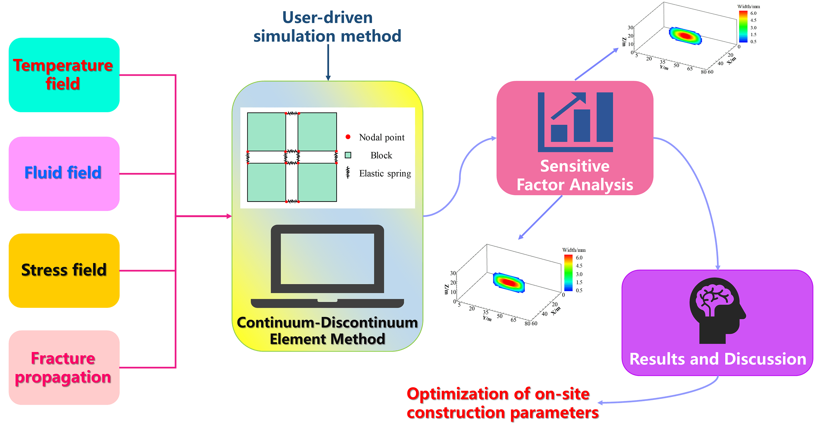
Hydraulic fracturing is a key technology for the efficient development of deep oil and gas reservoirs. However, fracture propagation behavior is influenced by rock elastoplasticity and thermal stress, making it difficult for traditional linear elastic models to accurately describe its dynamic response. To address this, this study employs the Continuum-Discontinuum Element Method (CDEM), incorporating an elastoplastic constitutive model, thermo-hydro-mechanical (THM) coupling effects, and cohesive zone characteristics at the fracture tip to establish a numerical model for hydraulic fracture propagation in deep elastoplastic reservoirs. A systematic investigation was conducted into the effects of fluid viscosity, reservoir temperature, injection rate, elastic modulus, and horizontal stress difference on fracture propagation. The findings show that a larger horizontal stress differential results in a more rectangular fracture geometry, a shorter fracture length, and a wider fracture. An increase in elastic modulus has a negligible impact on fracture length but reduces fracture width, resulting in a rounded rectangular morphology. Elevated reservoir temperature induces thermal tensile stress around the fracture, mitigating in-situ stress effects and reducing both breakdown and propagation pressures. Higher injection rates and fluid viscosity increase fracture initiation difficulty, promoting shorter but wider fractures with enhanced height growth beyond interlayer barriers. Additionally, horizontal stress significantly affects near-fracture plastic deformation: when the stress difference increases from 10 to 25 MPa, the maximum cumulative plastic strain in the surrounding rock rises by 66.67%. By integrating elastoplasticity and thermal stress effects, this study overcomes the limitations of conventional hydraulic fracturing simulations, offering novel insights for optimizing extraction strategies in deep unconventional reservoirs.Graphic Abstract
Keywords
From the perspective of global oil and gas development trends, deep reservoirs represent a key frontier for future exploration. Complementing conventional carbonate and clastic reservoirs, shale gas and coalbed methane are now prioritized in advanced geological exploration initiatives [1–5]. Due to their greater burial depth, deep hydrocarbon reservoirs exhibit distinct characteristics compared to shallow and intermediate formations, typically described as “three highs and one strong”: high temperature, high pressure, high geostress, and strong plasticity. Overall, they are characterized by ultra-low permeability, low porosity, high compressive strength, and limited fracture propagation capacity [6–8]. Therefore, it is essential to specifically account for the elasto-plastic behavior of deep reservoirs and the “three-high” geological conditions when studying the fracture propagation mechanisms during hydraulic fracturing. These studies lay the groundwork for optimizing production methods in deep, unconventional reservoirs [9,10].
The plastic deformation of rocks significantly impacts the propagation patterns and geometric configurations of hydraulic fractures. Previous studies have predominantly used one of the two criteria, Mohr-Coulomb or Drucker-Prager, to describe the plastic behavior of rocks or concrete. Wang et al. [11] created a completely integrated poroelastic model of hydraulic fracturing by combining a cohesive zone approach with Mohr-Coulomb plasticity theory. Their finite element simulations showed that plastic deformation in the formation elevates the fracture initiation pressure and net extension pressure, decreases the fracture propagation length, and increases the fracture width. Liu et al. [12] formulated a multi-physics coupled model for stimulated deep shale reservoirs by integrating the Drucker-Prager plastic yield criterion and cohesive zone theory with Finite Element Method-Finite Volume Method (FEM-FVM) hybrid modeling. Their computational results revealed that rock plastification induces a 15%–20% contraction in fracture activation zones, 30%–50% expansion in mean fracture aperture, and 40%–60% amplification of propagation pressure. Liao et al. [13] constructed a 3D FEM-based hydraulic fracturing framework incorporating the Drucker-Prager yield criterion to explore vertical fracture growth dynamics within stratified geological systems. Xing et al. [14] established a thermally responsive Drucker-Prager thermomechanical model for shale through integration of temperature-driven hardening criteria, cyclic thermal loading protocols, and fully coupled thermo-stress-strain constitutive relationships. The framework effectively captures shale’s nonlinear deformation behavior under multiscale confining pressure and temperature gradients. Sharafisafa et al. [15] conducted thermo-hydro-mechanical (THM) coupled simulations of hydraulic fracturing in deep high-temperature reservoirs using the finite-discrete element method (FDEM). Their results revealed that high fracture density significantly alters hydraulic fracture trajectories and exacerbates near-wellbore pressure accumulation, while thermal exchange between fluid and rock under elevated temperatures induces fracture branching. To date, studies that comprehensively address the combined effects of rock elastoplasticity and THM coupling on hydraulic crack propagation dynamics in deep reservoirs remain scarce.
State-of-the-art numerical simulation methodologies for hydraulic fracture propagation analysis predominantly encompass the Finite Element Method (FEM), Extended Finite Element Method (XFEM), Displacement Discontinuity Method (DDM), Discrete Element Method (DEM), and Continuum-Discontinuum Element Method (CDEM). The FEM has been extensively employed in reservoir geomechanics to tackle multiphysics challenges, demonstrating robust capabilities in precisely characterizing nonlinear elastoplastic behavior and resolving heterogeneous boundary constraints inherent to hydraulic fracturing simulations. However, FEM-based fracture propagation simulations are inherently governed by predefined mesh topologies, which fundamentally restrict the accurate representation of stochastic fracture propagation pathways and complex bifurcation behaviors [16–18]. The XFEM is an enhanced version of the traditional FEM. XFEM employs enrichment functions within conventional FEM displacement approximations to precisely resolve displacement discontinuities and stress singularities at fracture tips and void interfaces, while preserving the computational efficiency inherent to FEM’s sparse matrix formalism. Its key advantage lies in mesh independence, allowing fracture propagation without remeshing, which makes it suitable for simulating complex, branched, or intersecting fractures. However, XFEM typically struggles to accurately capture the interactions among multiple fractures and is limited in handling large-scale material flow and post-failure block movement [19–21]. The DDM is a boundary element-based numerical technique that models fractures as discontinuities in the displacement field. Since only the fractures are discretized, DDM offers high computational efficiency and has certain advantages in simulating randomly propagating fractures. However, its limitations include the omission of the rock matrix’s permeability and reduced accuracy of the traditional Stress Intensity Factor (SIF) approach under realistic in-situ stress conditions [22,23]. The DEM is effective in the simulation of initiation, propagation, and interaction of cracks in discontinuous media such as rock and concrete. It does not require predefining fracture paths and can naturally capture dynamic fracturing processes. DEM is well-suited for modeling the deformation of discrete blocks. However, it struggles to directly simulate the elastic or plastic deformation of continuous media, and it typically suffers from high computational cost and limited numerical accuracy [24–26]. The CDEM is a hybrid numerical approach for simulating the dynamic transition of materials from continuum to discontinuum states. Due to the dynamic coupling mechanisms between continuum and discontinuum mechanics, it suffers from high computational complexity and low efficiency when simulating material dynamic failure. However, this method enables the simulation of progressive failure processes by representing continuum characteristics through bulk elements and discontinuum behaviors through interfaces. Fracture propagation is achieved by the failure of element boundaries and internal bulk regions. By integrating the advantages of both continuum and discontinuum calculations—where continuum modeling employs methods such as the FEM, FVM, or spring-network models, while discontinuum modeling adopts the DEM—this framework provides a robust solution for addressing complex engineering problems involving multi-physics coupling [27–29].
Compared with the above computational simulation methods, CDEM effectively combines the advantages of continuum-based and discrete element-based methods. This methodology enables precise characterization of the complete process spanning continuous deformation, fracture nucleation, and subsequent block displacement. Such capability demonstrates distinct advantages in modeling highly nonlinear deformation and fracturing behavior inherent to deep elasto-plastic reservoirs. Consequently, a THM coupled model based on the CDEM framework was developed to simulate hydraulic crack propagation in deep elasto-plastic reservoirs, with the aim of systematically evaluating the impacts of key operational and geological factors on fracture propagation dynamics.
2 CDEM-Based Numerical Model of Fracture Propagation in Deep Reservoirs
2.1 Continuum-Discontinuum Element Method
CDEM establishes a time-explicit dynamic formulation employing fracturable element modules in Lagrangian computational schemes. By combining the FEM and the DEM, it provides a unified approach to model both continuous and discontinuous behaviors. This method captures progressive material failure by simulating fractures along block boundaries and within blocks. It can represent the entire process of material response, from continual deformation to fracture and subsequent block motion.
As illustrated in Fig. 1, the CDEM numerical framework comprises two fundamental components: blocks and interfaces. The blocks, discretized as Finite Elements, simulate continuum mechanical responses including plastic deformation and damage evolution. An interface is defined as the shared boundary between two adjacent blocks. It explicitly identifies behaviors such as fracture initiation and frictional sliding that are discontinuous. The interfaces in CDEM include both real and virtual types. Real interfaces delineate prospective fracture planes between adjacent blocks, whereas virtual interfaces mediate mechanical interactions and establish predefined propagation pathways for explicit crack advancement. Inter-block connectivity is governed by contact springs comprising orthogonally oriented normal and tangential stiffness components. The failure of these contact springs simulates the extension of fractures.
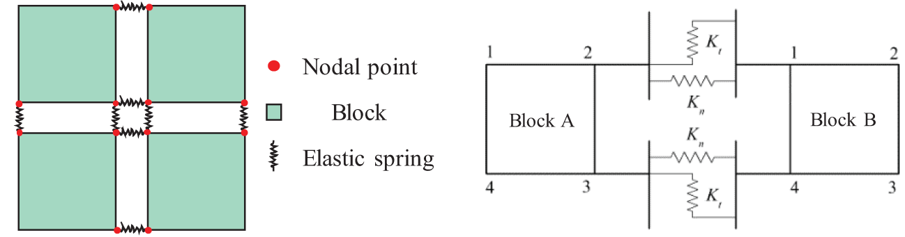
Figure 1: Schematic representation of the CDEM computational element
2.2 Multi-Physical Field Mathematical Model of Fracture Propagation in Deep Elastic-Plastic Reservoirs
The mathematical model of multi-physical field coupling of hydraulic fracture evolution in the deep elastic-plastic reservoir is established by using the continuous-discontinuous element method (CDEM). As illustrated in Fig. 2, a cohesive zone exists at the hydraulic fracture tip in the CDEM framework. When fracturing fluid is injected, stress concentration occurs at the fracture tip. Zones of high shear stress develop on either side of the tip, and the surrounding rock may undergo plastic deformation. As the fluid pressure continues to increase, the interface between blocks fails, initiating fracture propagation [30].
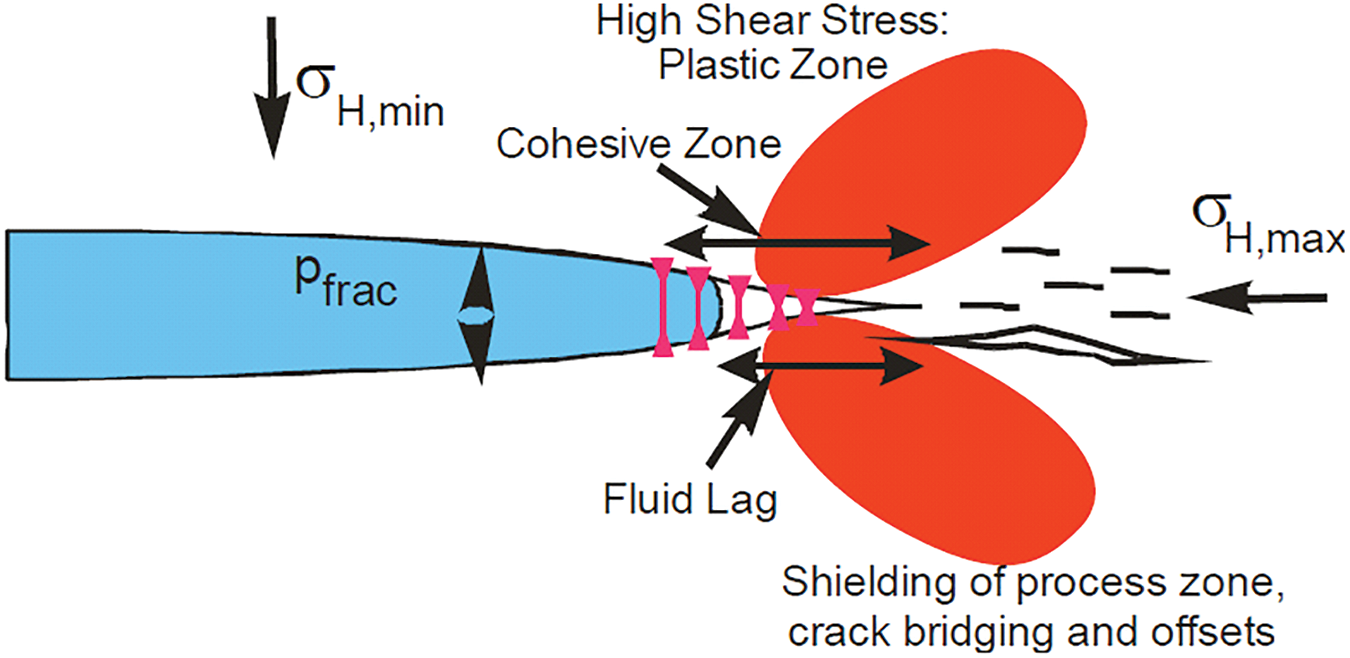
Figure 2: Schematic diagram of hydraulic fracture propagation [30]
Therefore, strong coupling exists among rock deformation, fluid flow, and fracture propagation. In the context of deep reservoirs, it is also necessary to consider the influence of temperature. As shown in Fig. 3, hydraulic fracture propagation in deep formations is a multi-physical coupling process. The mathematical model thus consists of four main components: (1) Solid Mechanics Model; (2) Fluid Flow Model; (3) Thermal Field Model; (4) Fracture Propagation Criterion.
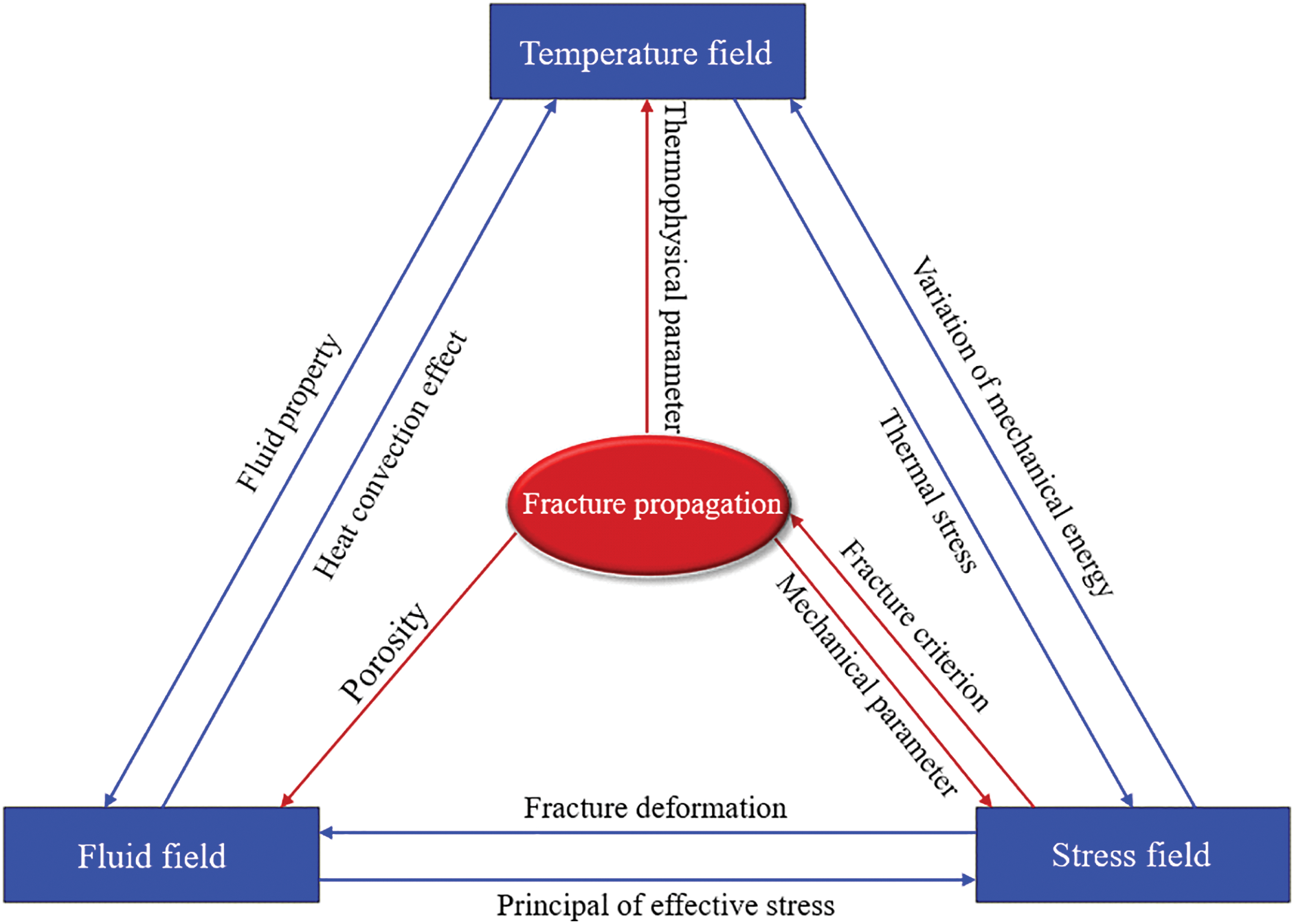
Figure 3: Schematic diagram of thermo-hydro-mechanical coupling
According to D’Alembert’s principle, a body in dynamic “equilibrium” satisfies the following motion governing equation [31]:
where
Currently, the elasto-plastic behavior of rock is commonly described using the Drucker–Prager criterion. The corresponding constitutive equation is given by:
where
The principal stress invariants
The parameters α and β are typically determined based on the Mohr-Coulomb criterion. When the respective vertices of the Mohr-Coulomb hexagonal pyramid and Drucker-Prager conical yield surfaces coincide, the constitutive correspondence between cohesion and internal friction angle can be mathematically established:
The effective stress tensor σij is formulated through the generalized Hooke’s constitutive framework as:
where
The elastic stiffness tensor
where
Considering the thermal strain and elastoplastic strain, the total strain tensor can be expressed as:
where
The plastic strain requires characterization of both its increment and flow direction, typically governed by either associated or non-associated flow rules. This study employs a non-associated flow rule for constitutive modeling:
where
The volumetric plastic strain is expressed as:
The thermoelastic strain
where
Substituting Eqs. (8), (11), and (13) into Eq. (6) yields the effective stress increment as:
where
Under elastoplastic deformation, the stress tensor is constrained to the yield criterion boundary, necessitating compliance with the consistency criterion for geological material yielding:
Eq. (13) can be expressed as:
Substituting Eq. (14) into Eq. (16) yields the plastic multiplier:
Substituting Eq. (17) into Eq. (14) yields the incremental formulation of the effective stress-strain constitutive model:
where
The strain and displacement fields must satisfy the kinematic compatibility equations:
where
According to Hooke’s law, the contact spring forces between the end nodes of contact springs at element interfaces are linearly related to their relative displacements. The predictive normal/tangential contact force components for the subsequent computational step are formulated through an incremental algorithmic framework:
where
In incompressible Newtonian viscous flow regimes, the fundamental field equations originate in the mass-momentum conservation principles:
where
The velocity at fracture element nodes can be described by the cubic law for fluid flow within fractures, which gives:
where
The nodal flow rate within fracture elements is determined through the element’s velocity field analysis.
where
The total flow rate at fracture nodes can be determined by accounting for the flow rate through individual fracture nodes and external source/sink terms, with its mathematical representation consistent with the relationship expressed in Eq. (26).
where
The dynamic relaxation method is employed to address the seepage field within fractures, with nodal pressure formulated as:
where
For pore fluid flow, Darcy’s law applies and can be expressed as:
where
The porous element’s volumetric flux is formulated as:
where
The total flow rate at pore element nodes can be determined by accounting for the flow rate through individual pore nodes and external source/sink terms, with its mathematical representation consistent with the relationship expressed in Eq. (31).
where
The nodal saturation can be expressed as:
where
A zero-pressure condition is prescribed at nodes where fluid saturation is less than 1. Upon reaching unit saturation, the total nodal fluid pressure can be expressed as:
The fluid exchange between pore and fracture elements can be calculated using Darcy’s law, expressed as:
where
By applying
Thermal disequilibrium develops between the injected fracturing fluid and formation matrix during hydraulic fracturing operations, triggering time-dependent thermal convection processes. The heat transfer mechanisms governing the evolution of the reservoir temperature field primarily include convective heat transfer and thermal conduction [33–35]. The governing equation for the reservoir heat field, under the local thermal equilibrium premise, can be expressed as follows:
where
2.2.4 Fracture Propagation Criterion
In the field of non-linear mechanics, the most commonly used approach to describe fracture propagation is the cohesive zone model. As shown in Fig. 4, the cohesive hydraulic fracture model consists of three regions: (1) Initial Fracture Zone; (2) Fracture Process Zone; (3) Intact Zone [36–38]. Progressive intensification of stress concentration occurs at fracture tips during sustained stimulation fluid injection. When the tip stress reaches the material’s ultimate strength, damage initiates, and a fracture process zone forms. Progressive crack aperture development induces attenuation of cohesive traction along the fracture plane. When the cohesive force drops to zero, the traction between the fracture surfaces vanishes, and the fracture fully propagates, resulting in a newly formed visible crack.
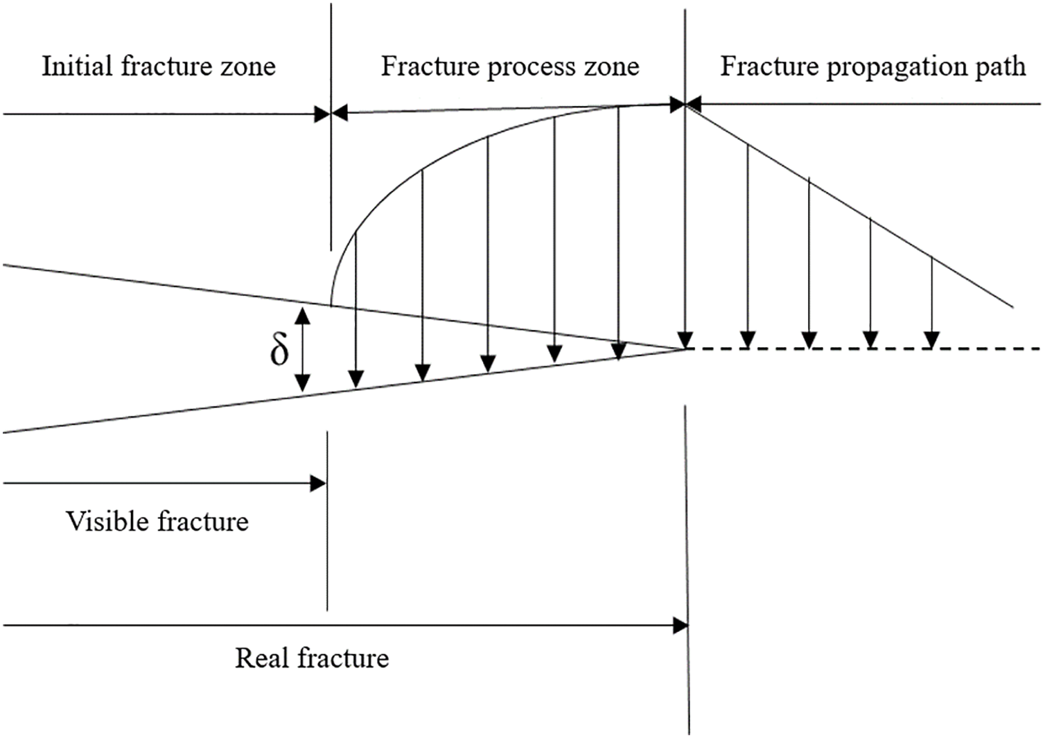
Figure 4: Schematic diagram of the cohesion model
According to the bilinear cohesion ontological model, as shown in Fig. 5, the interface behavior is considered linearly elastic prior to the onset of damage. When the fracture displacement reaches a critical threshold, the cohesive traction within the fracture process zone progressively diminishes to zero during crack propagation, ultimately resulting in complete fracture.
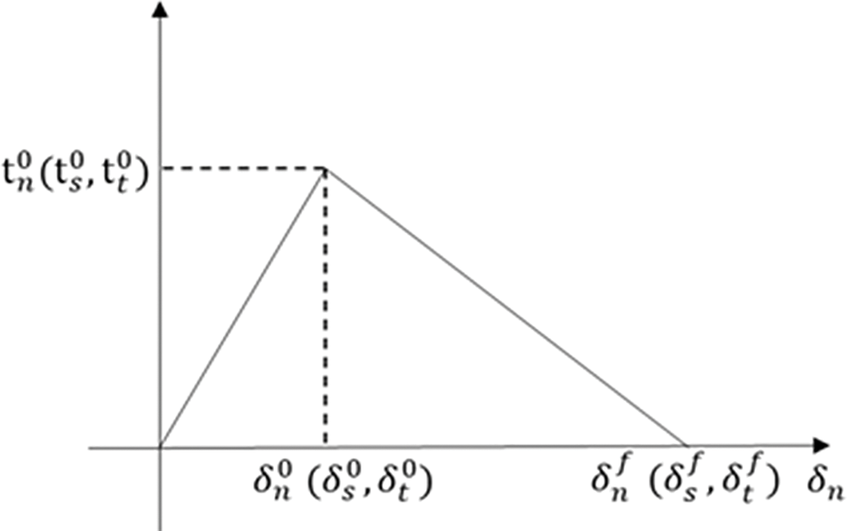
Figure 5: Schematic diagram of the bilinear traction-displacement ontological model
In Mode I fracture mechanics, the critical energy release rate
where
When the fracture tension displacement reaches a certain level, the fracture completely breaks, and the complete damage displacement can be expressed as:
The expression for cohesion at the fracture interface can be categorized as before and after the appearance of damage at the virtual interface:
where
where
2.3 Calculation Model for Fracture Propagation in Deep Reservoir Fracturing
2.3.1 Numerical Simulation Model
A 3D fracture propagation model for deep vertical well fracturing was established, as illustrated in Fig. 6. The model dimensions were set to 80 m × 60 m × 30 m, with the injection point located at the center. The numerical characterization of stress fields in deep geological structures was realized through the following loading configurations: maximum horizontal principal stress orientation aligned with the X-axis, minimum horizontal principal stress directionality assigned to the Y-axis, and high-stress barrier layers were established at the upper and lower boundaries of the reservoir to simulate the vertical stress confinement conditions in actual formations. To enhance computational efficiency while ensuring model accuracy, hexahedral meshes with structured gridding were employed. Uniformly distributed 1 m grids were implemented perpendicular to the minimum principal stress direction, while gradually coarsened grids were adopted along the minimum principal stress direction, featuring a 1 m grid size at the central region and an 8 m at the outer boundaries.
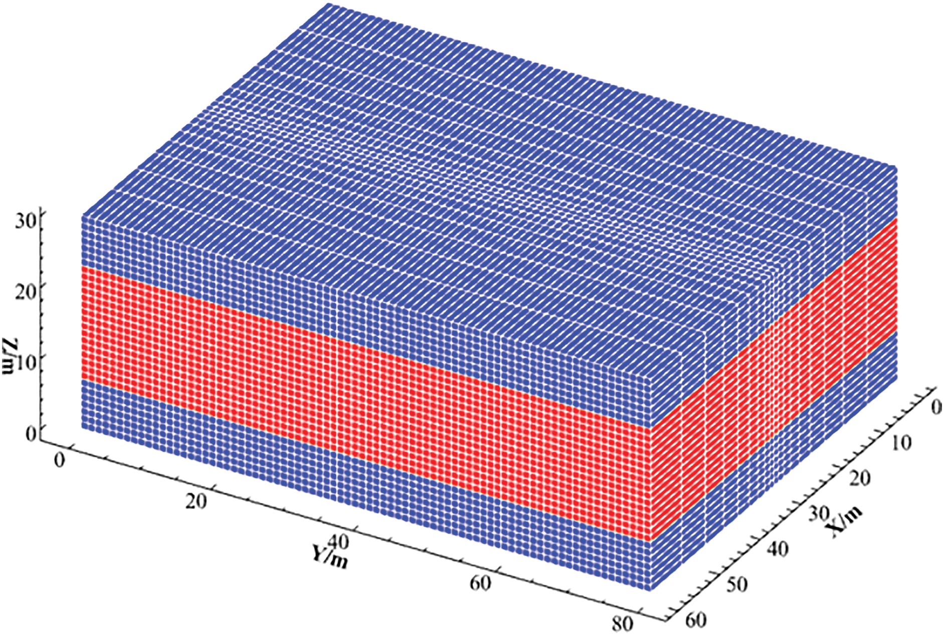
Figure 6: Numerical simulation model of hydraulic fracturing
The relevant parameters in the model are summarized in Table 1, which mainly include rock mechanical parameters, porosity, permeability, geostress, temperature, and so on. In this hydraulic fracturing simulation, water-based fracturing fluid was utilized, with fluid parameters configured based on the properties of water.

The model used in this paper focuses on viscously dominated hydraulic fracture extensions, and in order to verify the accuracy of the model, reference is made to the analytical model of circular fracture penny derived by Dontsov [39] for comparison. Dontsov et al. derived an analytical equation for the viscous dominated circular hydraulic fracture as:
where
According to Table 1, a three-dimensional hydraulic fracture extension model is established as shown in Fig. 7a, with the model size of 60 m × 60 m × 10 m, the grid size of 1 m in the plane, and the grid size of 2.5 m in the vertical direction, and the injection point is set at the center of the model, the displacement is set at 0.02 m3/s of the constant displacement, the elastic modulus is 25 GPa, and the fracturing time is 50 s. As shown in Fig. 7b, the final simulation results indicate that the fracture morphology is circular and that the overall area is consistent with the analytical solution.
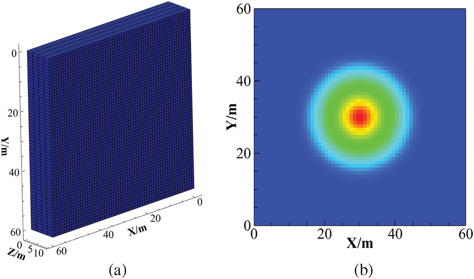
Figure 7: Comparison of Penny fracture numerical model and analytical model results. (a) Numerical model schematic; (b) fracture width distribution
Temporal evolution of fracture aperture and propagation distance at the model centroid was tracked to benchmark numerical solutions against analytical predictions, with comparative results shown in Fig. 8. The average discrepancy between numerical and analytical solutions for fracture width is 3.6%, while that for fracture length is 1.7%. The numerical results in the viscous-dominated regime are in excellent accordance with the analytical results, thereby validating the precision of the proposed 3D fracture propagation model.
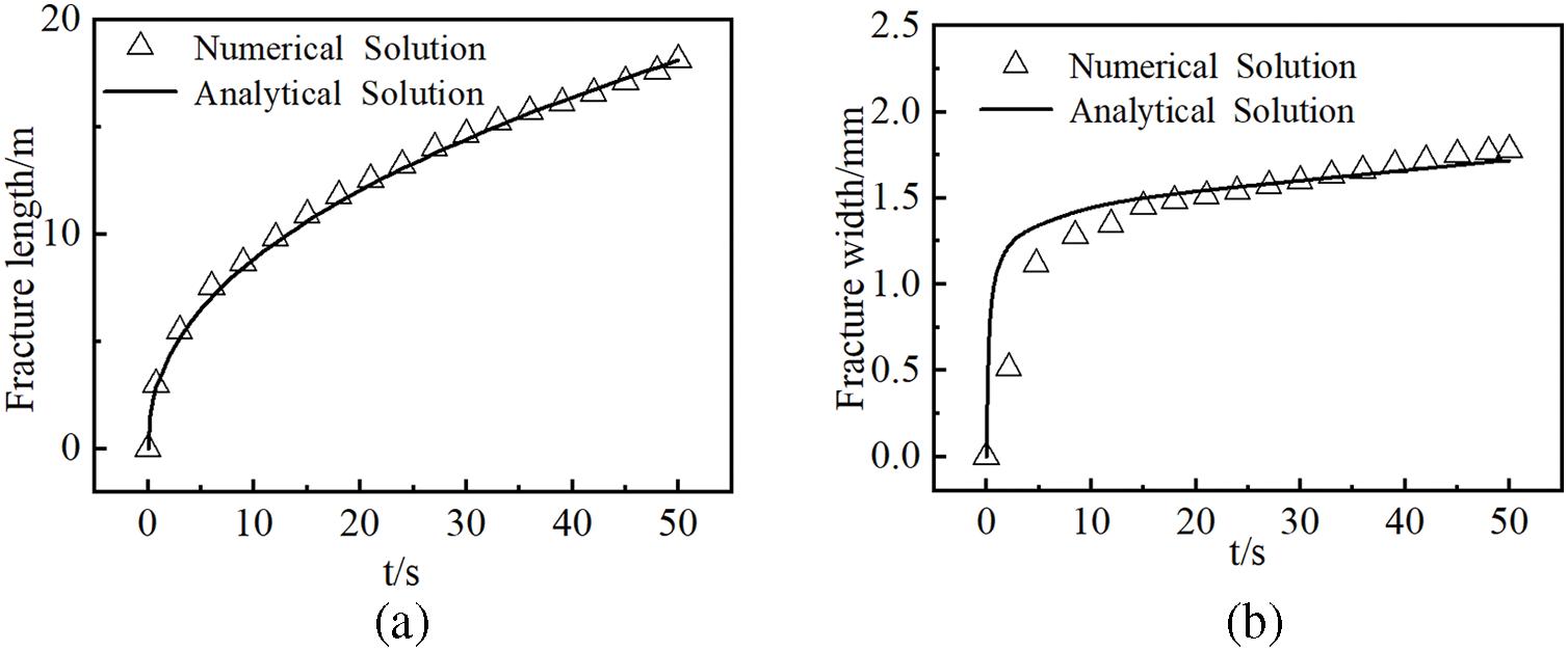
Figure 8: Comparison of numerical simulation and analytical solutions for hydraulic crack propagation: (a) fracture length vs. time; (b) fracture width vs. time.
3 Numerical Simulation Results
3.1 Influence of Differential Horizontal Ground Stress
By maintaining constant geological and engineering parameters while holding the maximum horizontal principal stress fixed and varying exclusively the minimum horizontal principal stress, this study investigated hydraulic fracture propagation characteristics in deep reservoirs under differential horizontal stress conditions ranging from 10 to 25 MPa, with corresponding propagation patterns presented in Fig. 9. As graphically demonstrated in the accompanying illustration, an increase in the horizontal in-situ stress difference results in shorter hydraulic fracture length, greater fracture width, and a transition in fracture geometry toward a rectangular morphology.
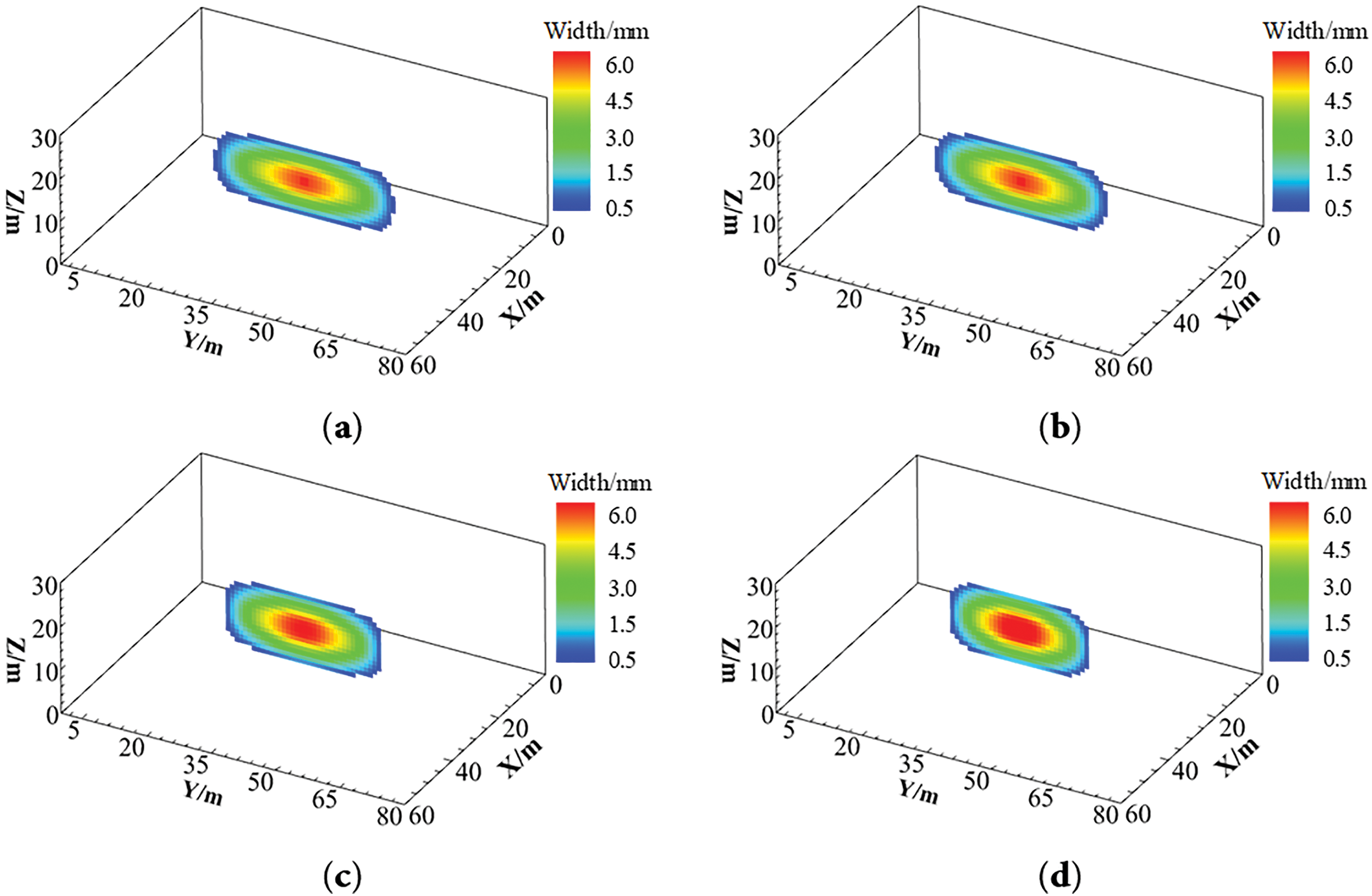
Figure 9: Geometric shape diagram of hydraulic fracture under different horizontal stress difference. (a) 10 MPa; (b) 15 MPa; (c) 20 MPa; (d) 25 MPa
As shown in Fig. 10, an elevated horizontal in-situ stress difference makes crack propagation more challenging, accompanied by significant elevation of both breakdown pressure and propagation pressure in the reservoir. Elevating the horizontal stress differential from 10 to 25 MPa induced a 10.61 MPa escalation in breakdown pressure and a 6.62 MPa augmentation in net extension pressure, concurrent with a 21.58% contraction in fracture propagation length and a 12.53% expansion in aperture width. Fig. 11 quantifies a 66.7% escalation in peak cumulative plastic strain within the perifracture domain resulting from enhanced horizontal stress contrast. Increasing the horizontal stress difference will strengthen the stress concentration effect at the tip of the fracture extension process, and the rocks around the tip of the fracture are more likely to enter the plastic state during the extension process, which makes the fracture consume more energy during the extension process, and then reduces the extension capacity of the fracture.
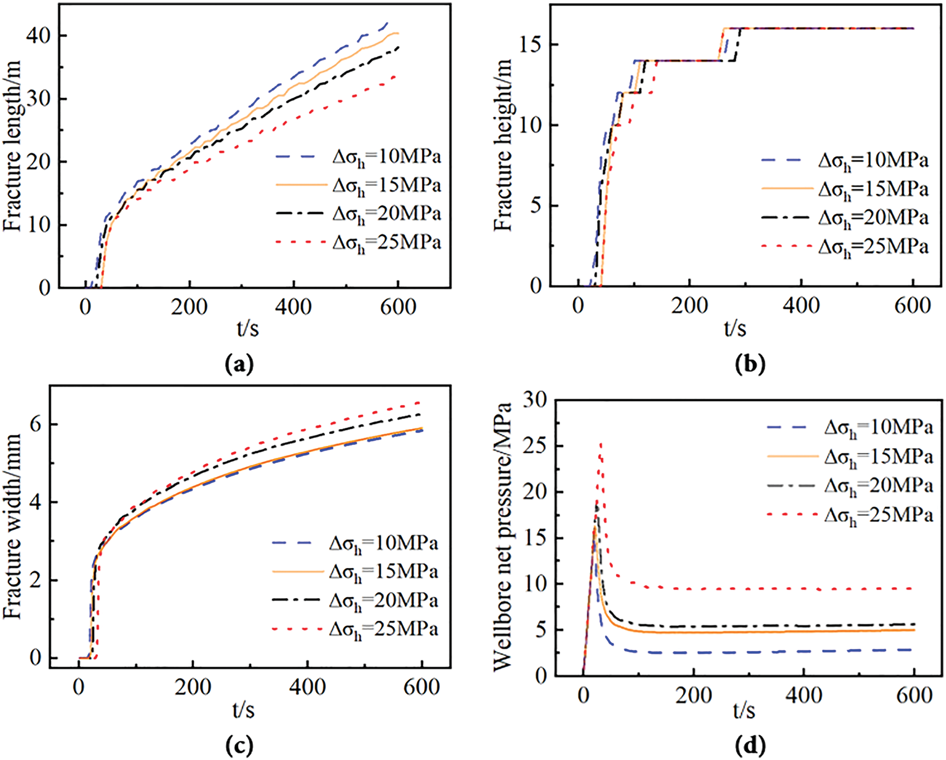
Figure 10: Numerical simulation results of hydraulic fracturing under different levels of in-situ stress differences. (a) Fracture length vs time curve; (b) fracture height vs time curve; (c) fracture width at the injection point vs time curve; (d) net pressure at the wellbore vs time curve
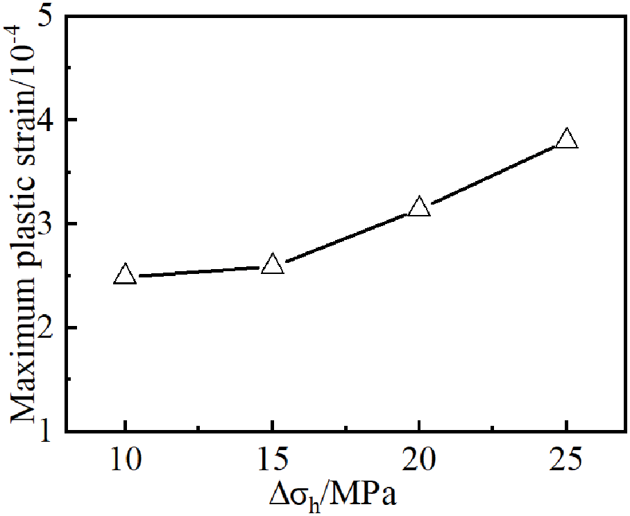
Figure 11: Maximum cumulative plastic strain at different levels of in-situ stress differences
3.2 Influence of Modulus of Elasticity
Keeping the rest of the geological parameters and construction parameters unchanged, the modulus of elasticity of the formation was changed (15, 20, 25, 30 GPa) and the impact of the deep reservoir’s modulus of elasticity on fracture extension was examined. The results are shown in Fig. 12. With increasing elastic modulus of the formation, the hydraulic fracture geometry transitions toward a rounded rectangular morphology. While the fracture length exhibits negligible variation, the fracture width progressively diminishes.
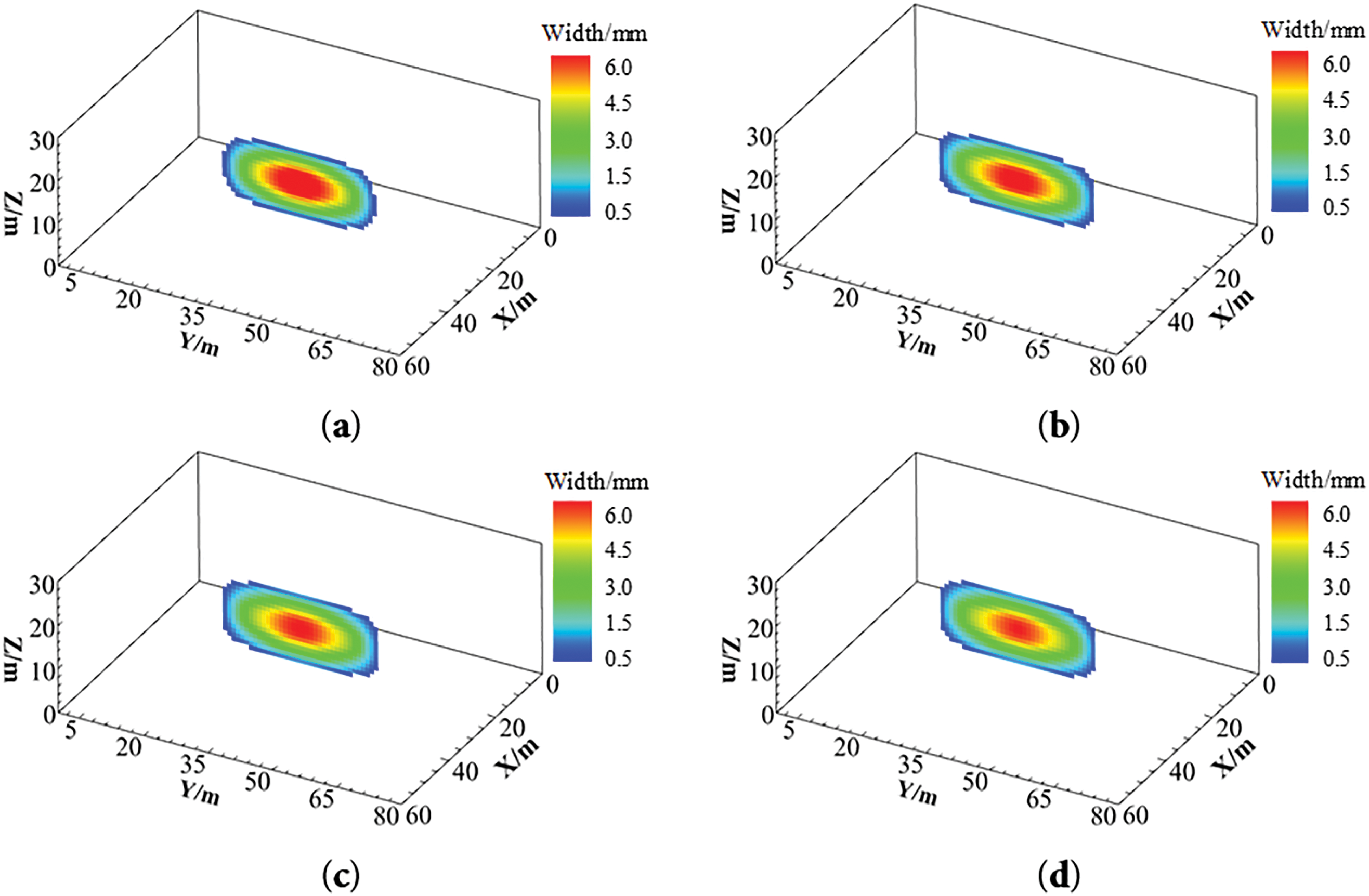
Figure 12: Hydraulic fracture patterns in different strata with different modulus of elasticity. (a) 15 GPa; (b) 20 GPa; (c) 25 GPa; (d) 30 GPa
Numerical simulation results (Fig. 13) indicate that increasing the elastic modulus significantly influences hydraulic fracture width and height propagation. Specifically, fracture width decreases markedly, vertical propagation time shortens, and both breakdown and propagation pressures increase substantially. As the elastic modulus increases from 15 to 30 GPa, hydraulic fracture width decreases by 12.29%, vertical propagation time reduces by 32.05%, reservoir breakdown pressure rises by 9.98 MPa, and fracture propagation pressure increases by 2.71 MPa. As shown in Fig. 14, under deep reservoir conditions, elevating the elastic modulus exhibits limited efficacy in enhancing rock plasticity. The maximum cumulative plastic strain in the reservoir decreases by only 7.37% with increasing elastic modulus. From the thermal stress calculation formula, the increase of elastic modulus will lead to the increase of thermal stress and thus the decrease of original stress in the formation, which will make the reservoir easier to rupture. From a petrophysical perspective, the elastic modulus primarily represents the rock’s resistance to elastic deformation. Higher elastic modulus corresponds to greater rock strength and reduced susceptibility to fracturing, thereby requiring elevated fluid pressure within the fracture and resulting in increased reservoir breakdown pressure and propagation pressure. In reservoirs with high elastic modulus, enhanced energy propagation efficiency enables fractures to propagate preferentially along the maximum principal stress direction after rupture, generating fractures with greater length and reduced width. Concurrently, the vertical growth tendency of fractures is amplified, leading to fracture geometries that more closely approximate rectangular profiles.
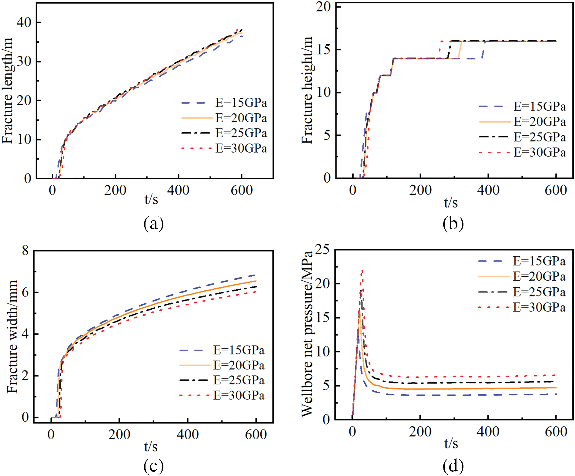
Figure 13: Numerical simulation results curve of hydraulic fracturing with different elastic modulus. (a) Fracture length vs time curve; (b) fracture height vs time curve; (c) fracture width at the injection point vs time curve; (d) Net pressure at the wellbore vs time curve
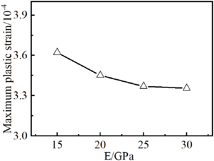
Figure 14: Maximum cumulative plastic strain for different modulus of elasticity
3.3 Influence of Reservoir Temperature
The fracture propagation behavior in deep reservoirs under varying temperatures (50°C, 200°C, 400°C, 600°C) was investigated while maintaining constant geological and operational parameters. Numerical results (Fig. 15) demonstrate that increasing reservoir temperature induces significant variations in fracture geometric parameters, while the fundamental fracture morphology remains largely unchanged.
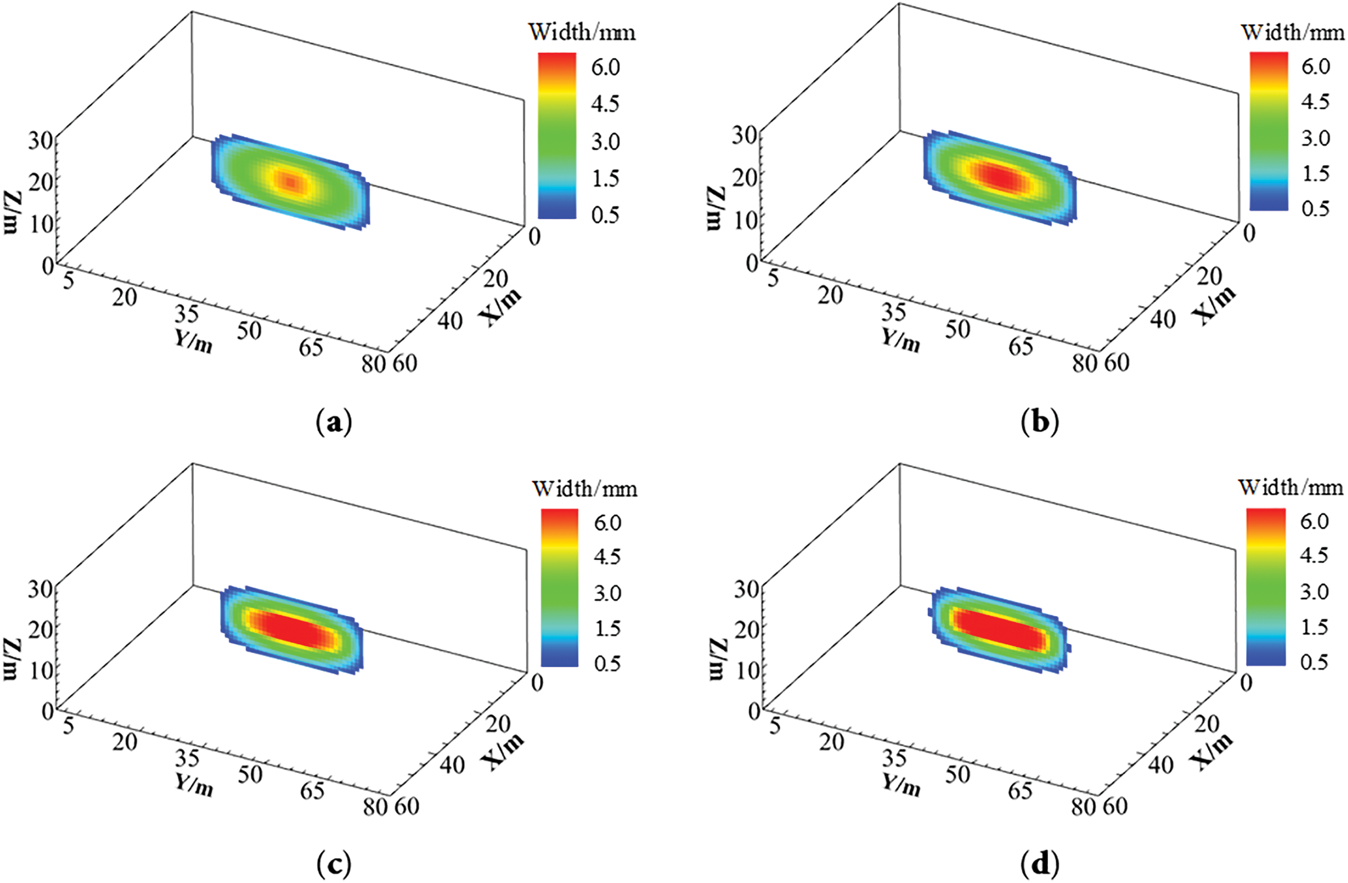
Figure 15: Hydraulic fracture morphology at different reservoir temperatures. (a) 50°C; (b) 200°C; (c) 400°C; (d) 600°C
As shown in Fig. 16, increasing reservoir temperature exerts a pronounced influence on hydraulic fracture propagation. Specifically, breakdown pressure, propagation pressure, and fracture length decrease with rising temperature, whereas fracture width increases. Under progressive thermal loading elevating the reservoir from 50°C to 600°C, the reservoir breakdown pressure decreased by 9.92 MPa, with the fracture length reduced by 6.68 m and the fracture width increased by 1.89 mm. Fig. 17 reveals that variations in reservoir temperature exhibit minimal impact on cumulative plastic strain in the rock, suggesting that temperature is not a dominant factor controlling reservoir plastic deformation. The temperature difference between the high-temperature reservoir and the low-temperature fracturing fluid generates thermal tensile stress around the fractures. This thermal stress reduces the impact of in-situ stresses, making the reservoir more susceptible to failure. Thereby reducing the rock breakdown pressure and propagation pressure. Nevertheless, due to the thermal cooling effects propagating slower than the fracture advancement rate, the thermal tensile stresses exhibited negligible influence at the fracture tip. This resulted in no enhancement of fracture propagation capacity along the length direction, while under constant injection rate, the fracture width experienced significant enlargement. In deep reservoirs, although the injection of low-temperature fluid can significantly decrease formation crack pressure and reduce the impact of high pressure at depth, the length of the fracture will decrease accordingly. Combined with the effects of rock plastic deformation, this ultimately makes extending fractures in deeper reservoirs more difficult than in shallower ones.
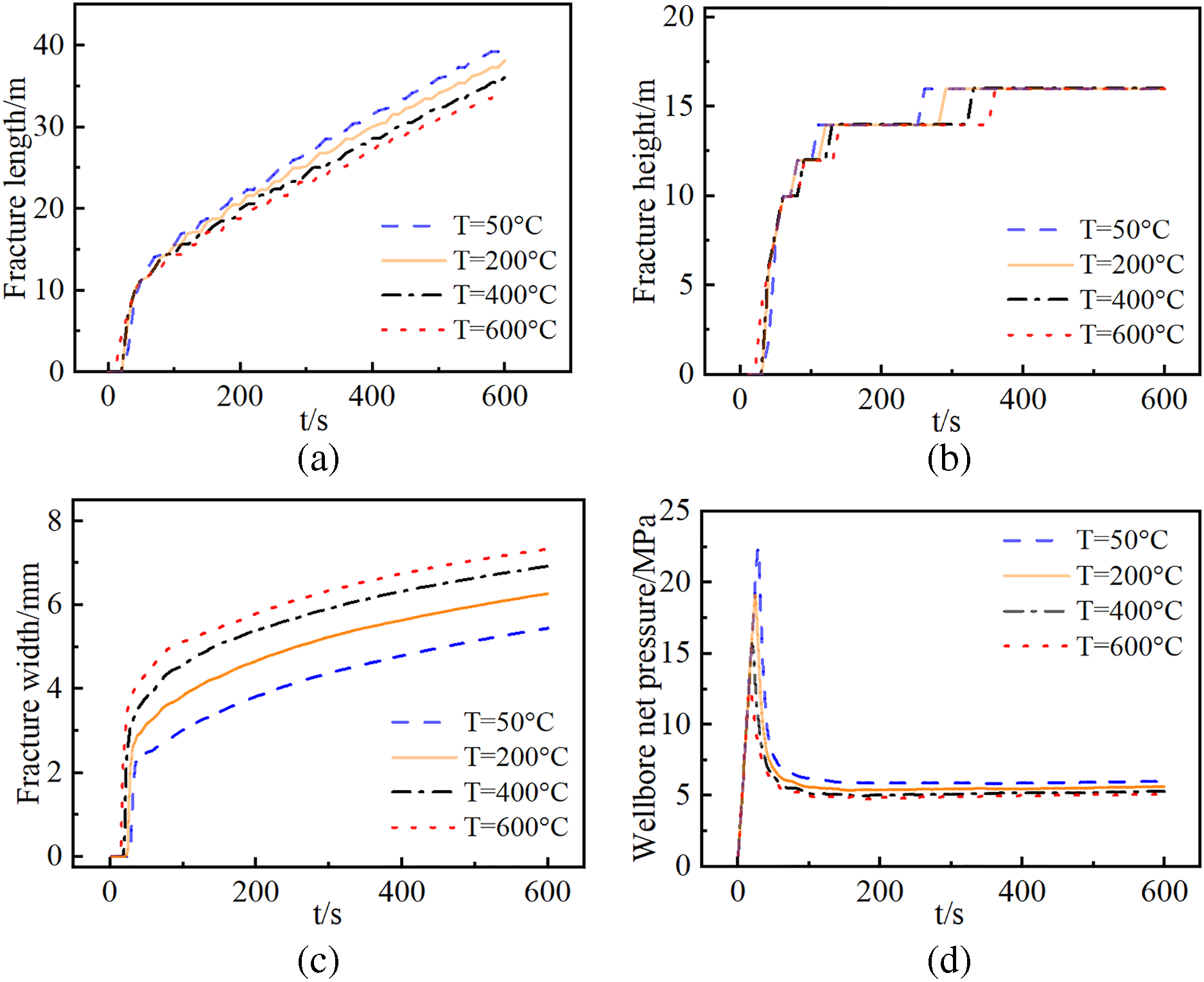
Figure 16: Numerical simulation results of hydraulic fracturing at different reservoir temperatures. (a) Fracture length vs time curve; (b) fracture height vs time curve; (c) fracture width at the injection point vs time curve; (d) net pressure at the wellbore vs time curve

Figure 17: Maximum cumulative plastic strain at different reservoir temperatures
3.4 Influence of Fracturing Fluid Displacement
Hydraulic fracturing simulations were conducted under constant total fluid volume while varying injection rates (0.9, 1.8, 3.6, and 5.4 m3/min) and corresponding injection durations (1200, 600, 300, and 200 s) to investigate their effects on fracture propagation in deep elastic-plastic reservoirs. As shown in Fig. 18, increasing injection rate results in significantly reduced fracture length, increased fracture width, and a transition toward short-wide fracture geometry. When the injection rate reaches 3.6 m3/min, the fracture height penetrates the barrier layers.
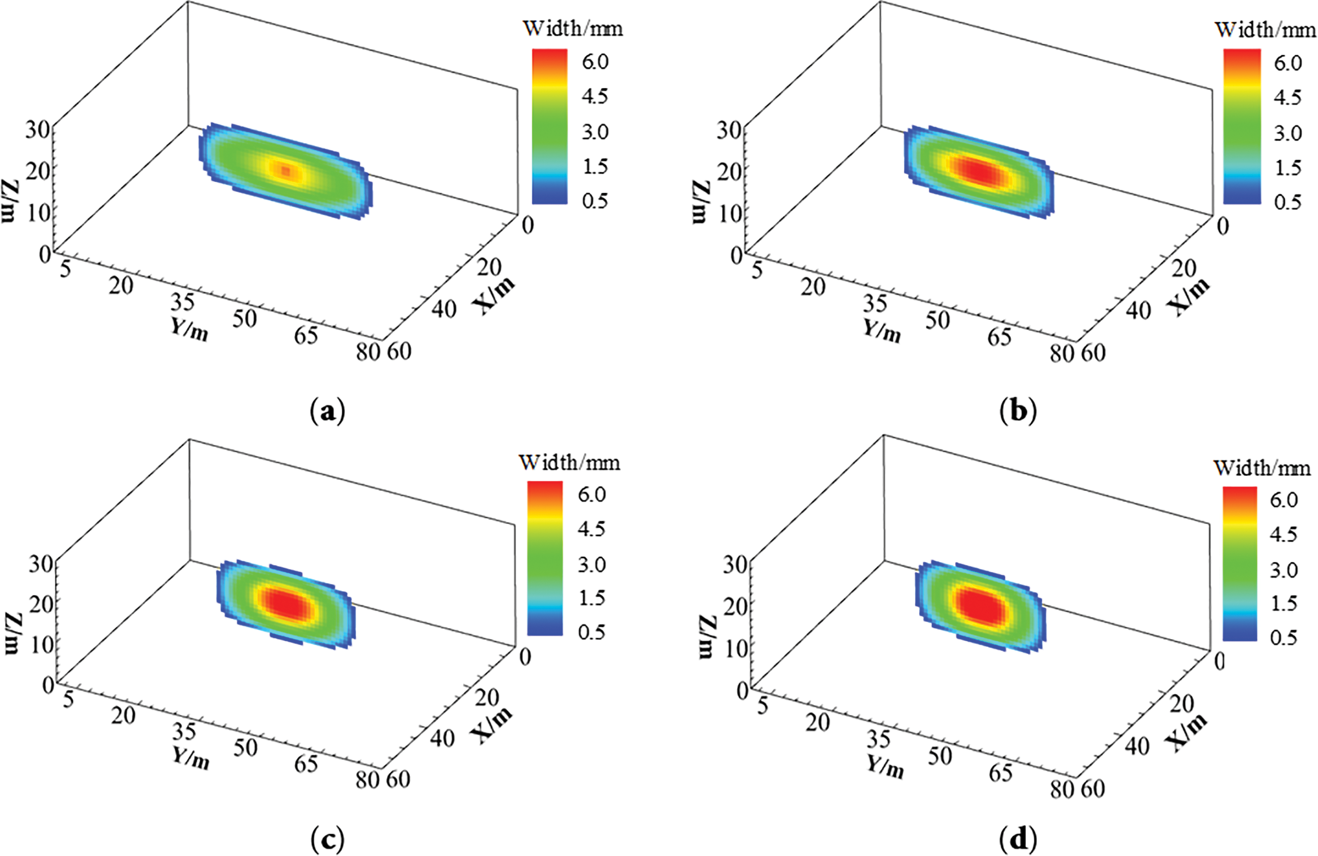
Figure 18: Fracture width distribution under different injection rates. (a) 0.9 m3/min; (b) 1.8 m3/min; (c) 3.6 m3/min; (d) 5.4 m3/min
As shown in Fig. 19, increasing the injection rate elevates fracture propagation resistance, resulting in significant rises in reservoir breakdown pressure and propagation pressure. As the rate of injection went up from 0.9 to 5.4 m3/min, the reservoir’s breakdown pressure climbed by 5.56 MPa. The crack propagation pressure increased by 3.09 MPa, which was accompanied by a 11.71 m reduction in crack length and a 1.63 mm increase in crack width. Augmented injection rates generate intensified pressurization kinetics within fractures, causing concomitant escalation of fracture initiation pressure and net propagation pressure. This reduces the fracture’s ability to extend in the longitudinal direction, while increasing the fracture width and enhancing its ability to break through vertical barriers. Moreover, at high injection rates, the contact time between the low-temperature fluid and the high-temperature reservoir rock is shortened, limiting thermal exchange. As a result, the influence of thermal stress is reduced, further increasing the breakdown and propagation pressures compared to lower injection rates. As shown in Fig. 20, the effect of injection rate on plastic deformation is relatively minor, exhibiting a trend of initial decrease followed by an increase with rising injection rate. Compared to shallow reservoirs, deep reservoirs are more sensitive to injection rate due to the combined effects of high temperature and rock plasticity. To maximize fracture length in deep reservoirs, fracturing designs should prioritize lower injection rates whenever possible.
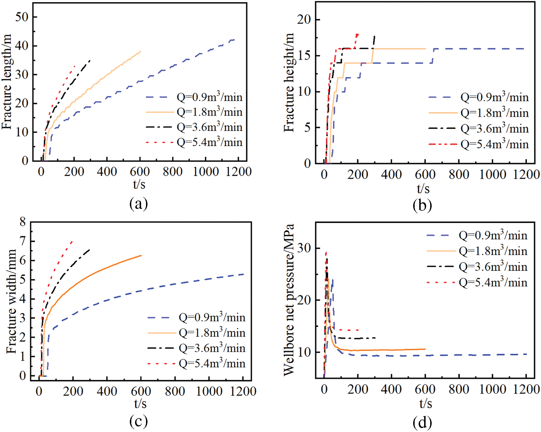
Figure 19: Hydraulic fracture geometry under different injection rates. (a) Fracture length vs time curve; (b) fracture height vs time curve; (c) fracture width at the injection point vs time curve; (d) net pressure at the wellbore vs time curve
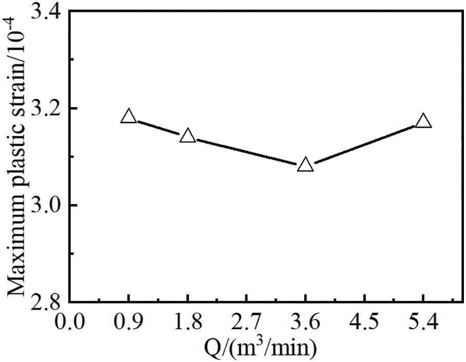
Figure 20: Maximum accumulated plastic strain under different injection rates
3.5 Influence of Fracturing Fluid Viscosity
Hydraulic fracturing simulations were conducted under constant geological and operational conditions with varying fracturing fluid viscosities (1, 2, 5, and 10 mPa·s) to assess their impacts on fracture propagation in deep reservoirs. As shown in Fig. 21, under constant injection rate, increasing fracturing fluid viscosity significantly reduces fracture length while enhancing fracture width. When viscosity reaches 5 mPa·s, fracture height propagation breaches interlayer barriers, and the fracture geometry transitions toward a circular morphology.
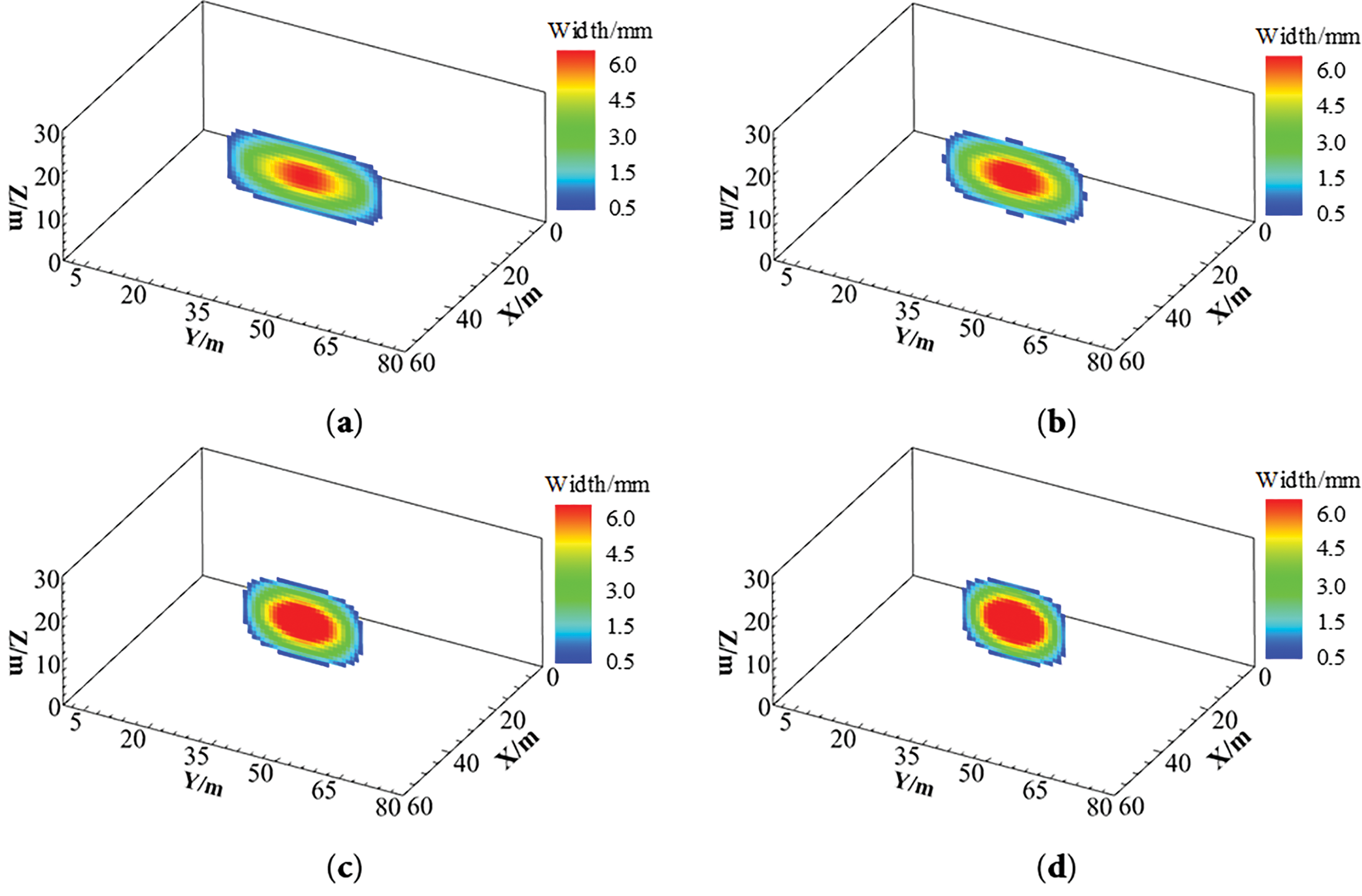
Figure 21: Hydraulic fracture morphology under varying fracturing fluid viscosities. (a) 1 mPa·s; (b) 2 mPa·s; (c) 5 mPa·s; (d) 10 mPa·s
As shown in Fig. 22, increasing fracturing fluid viscosity leads to significant increases in reservoir breakdown pressure and propagation pressure. As the viscosity of the fracturing fluid raises from 1 to 10 mPa·s, breakdown pressure rises by 6.90 MPa, propagation pressure increases by 9.78 MPa, fracture length decreases by 13.22 m, and fracture width enlarges by 3.71 mm. High-viscosity fracturing fluids exhibit restricted flow mobility within fractures and reduced fluid loss to the matrix, promoting pressure accumulation within the fracture. This elevates the pressure gradient, thereby increasing both the reservoir breakdown pressure and fracture propagation pressure. The increased difficulty in fracture propagation results in enhanced fracture width and improved capability to penetrate barrier layers. As the viscosity of the fracturing fluid reaches 5 mPa·s, the fracture penetrates the barrier layers vertically. As shown in Fig. 23, the viscosity of the fracturing fluid has a limited impact on the plastic behavior of the rock surrounding the fracture. In deep reservoir environments, the adverse effects of high-viscosity fluids on fracture propagation can compound with the influence of rock plasticity, making fracture extension even more difficult.
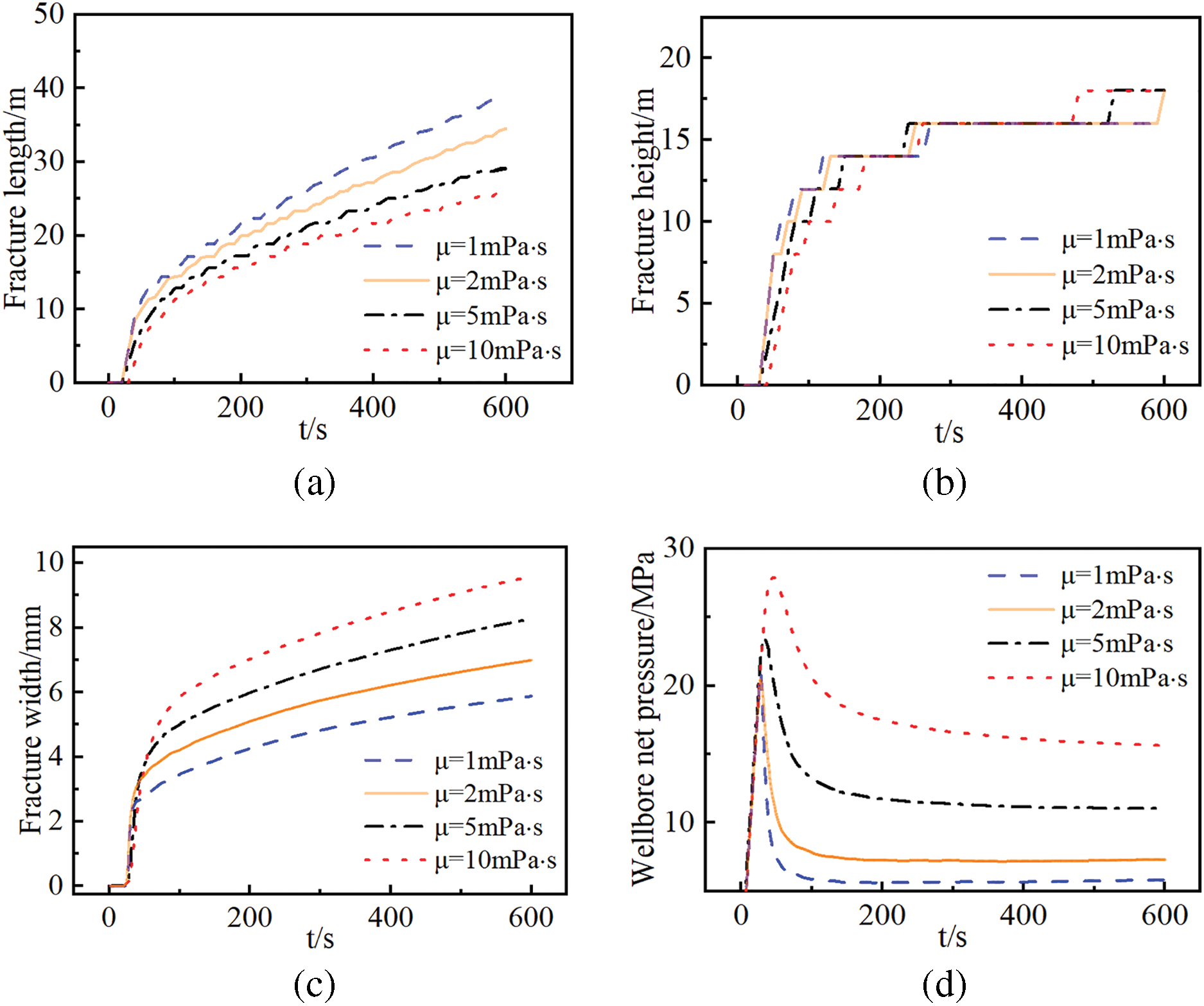
Figure 22: Numerical simulation results of hydraulic fracturing under different fracturing fluid viscosities. (a) Fracture length vs time curve; (b) fracture height vs time curve; (c) fracture width at the injection point vs time curve; (d) net pressure at the wellbore vs time curve
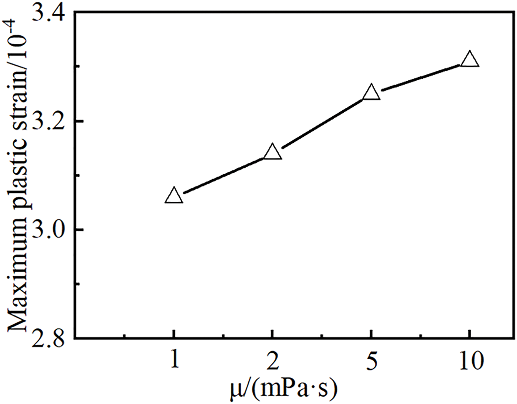
Figure 23: Maximum accumulated plastic strain under different fracturing fluid viscosities
This study used the CDEM to create a numerical model of hydraulic crack propagation in deep reservoirs. Using a controlled variable approach, the impact of horizontal in-situ stress differences, elastic modulus, reservoir temperature, injection rate, and fluid viscosity on fracture length, height, and width was systematically examined. The key findings are as follows:
1. During hydraulic fracturing in deep reservoirs, rock plastic deformation consumes additional energy, weakens the stress concentration at the fracture tip, and makes fracture propagation more difficult. This leads to higher breakdown and propagation pressures, reduced fracture length, and increased fracture width.
2. In deep reservoirs, elevated horizontal in-situ stress differences and elastic modulus significantly increase the difficulty of rock fracturing. A larger horizontal stress difference leads to shorter fracture length, greater fracture width, and a transition of hydraulic fracture geometry toward rectangular morphology. Conversely, reservoirs with higher elastic modulus tend to develop longer and narrower fractures.
3. Elevated reservoir temperature enhances the effect of thermal tensile stress, significantly reducing the breakdown pressure. However, the resulting hydraulic fractures tend to be shorter in length and wider in aperture.
4. Higher injection rates and fracturing fluid viscosities increase the difficulty of reservoir breakdown, resulting in shorter but wider hydraulic fractures. Concurrently, the fractures demonstrate enhanced capability to penetrate barrier layers in the vertical direction.
Acknowledgement: Thank you to Shaanxi Yanchang Petroleum (Group) Co., Ltd., Natural Gas Research Institute Branch and China University of Petroleum (East China) Deep Oil and Gas Ministry of Education Key Laboratory for this work support.
Funding Statement: This research was financially supported by the Shandong Provincial Natural Science Foundation for Distinguished Young Scholars (Grant No. ZR2024JQ012). This research was financially supported by the National Natural Science Foundation of China (General Program, Grant No. 52474069). This research was financially supported by the Natural Gas Research Institute of Shaanxi Yanchang Petroleum (Group) Co., Ltd. (Grant No. TYTY0824SFW0003).
Author Contributions: The authors confirm their contributions to the paper as follows: Study conception and design: Xin Wan, Shuyi Li; Data collection: Tiankui Guo, Ming Chen; Analysis and interpretation of results: Xing Yang; Draft manuscript preparation: Guchang Zhang, Zi’ang Wang. All authors reviewed the results and approved the final version of the manuscript.
Availability of Data and Materials: The dataset generated and analyzed during the current study is available from the corresponding author upon reasonable request.
Ethics Approval: Not applicable.
Conflicts of Interest: The authors declare no conflicts of interest to report regarding the present study.
References
1. Jia C. Key scientific and technological problems of petroleum exploration and development in deep and ultra-deep formation. J China Univ Pet. 2023;47(5):1–12. (In Chinese). doi:10.3969/j.issn.1673-5005.2023.05.001. [Google Scholar] [CrossRef]
2. Zhao J, Ren L, Lin C, Lin R, Hu D, Wu J, et al. A review of deep and ultra-deep shale gas fracturing in China: status and directions. Renew Sustain Energy Rev. 2025;209:115111. doi:10.1016/j.rser.2024.115111. [Google Scholar] [CrossRef]
3. Qu Z, Wang J, Guo T, Shen L, Liao H, Liu X, et al. Optimization on fracturing fluid flowback model after hydraulic fracturing in oil well. J Petrol Sci Eng. 2021;204(4):108703. doi:10.1016/j.petrol.2021.108703. [Google Scholar] [CrossRef]
4. Wu H, Kong X. Analysis of geological characteristics and potential factors of formation damage in coalbed methane reservoir in Northern Qinshui basin. Sci Rep. 2025;15(1):3025. doi:10.1038/s41598-025-87026-3. [Google Scholar] [PubMed] [CrossRef]
5. Guo XS, Hu DF, Li YP, Duan JB, Zhang XF, Fan XJ, et al. Theoretical progress and key technologies of onshore ultra-deep oil/gas exploration. Engineering. 2019;5(3):233–58. doi:10.1016/j.eng.2019.01.012. [Google Scholar] [CrossRef]
6. Han L, Li X, Liu Z, Guo W, Cui Y, Qian C, et al. Study on rock mechanics characteristics of deep shale in Luzhou block and the influence on reservoir fracturing. Energy Sci Eng. 2023;11(1):4–21. doi:10.1002/ese3.1360. [Google Scholar] [CrossRef]
7. Zhang Y, Zhao GF. A global review of deep geothermal energy exploration: from a view of rock mechanics and engineering. Geomech Geophys Geo Energy Geo Resour. 2019;6(1):4. doi:10.1007/s40948-019-00126-z. [Google Scholar] [CrossRef]
8. Jiang M, Liu Q. Geochemical characteristics of ultra-deep natural gases. Org Geochem. 2025;203:104964. doi:10.1016/j.orggeochem.2025.104964. [Google Scholar] [CrossRef]
9. Lin R, Peng S, Zhao J, Jiang H, Ren L, Zhou B, et al. Multiple hydraulic fracture propagation simulation in deep shale gas reservoir considering thermal effects. Eng Fract Mech. 2024;303(8):110147. doi:10.1016/j.engfracmech.2024.110147. [Google Scholar] [CrossRef]
10. Yang S, Zheng K, Zhang J, Dai N, Wang L, Wang Z, et al. Study on the influencing factors of hydraulic fracture propagation in deep unconventional gas reservoirs. Chem Technol Fuels Oils. 2024;60(3):802–11. doi:10.1007/s10553-024-01737-3. [Google Scholar] [CrossRef]
11. Wang H, Marongiu-Porcu M, Economides MJ. Poroelastic and poroplastic modeling of hydraulic fracturing in brittle and ductile formations. SPE Prod Oper. 2016;31(1):47–59. doi:10.2118/168600-pa. [Google Scholar] [CrossRef]
12. Liu W, Zeng Q, Yao J. Poroelastoplastic modeling of complex hydraulic-fracture development in deep shale formations. SPE J. 2021;26(5):2626–50. doi:10.2118/205357-pa. [Google Scholar] [PubMed] [CrossRef]
13. Liao S, Hu J, Zhang Y. Mechanism of hydraulic fracture vertical propagation in deep shale formation based on elastic-plastic model. Eng Fract Mech. 2024;295(5):109806. doi:10.1016/j.engfracmech.2023.109806. [Google Scholar] [CrossRef]
14. Xing Y, Zhang G, Li S. Thermoplastic constitutive modeling of shale based on temperature-dependent Drucker-Prager plasticity. Int J Rock Mech Min Sci. 2020;130(6):104305. doi:10.1016/j.ijrmms.2020.104305. [Google Scholar] [CrossRef]
15. Sharafisafa M, Aliabadian Z, Sato A, Shen L. Coupled thermo-hydro-mechanical simulation of hydraulic fracturing in deep reservoirs using finite-discrete element method. Rock Mech Rock Eng. 2023;56(7):5039–75. doi:10.1007/s00603-023-03325-z. [Google Scholar] [CrossRef]
16. Chen Z, Jeffrey RG, Zhang X, Kear J. Finite-element simulation of a hydraulic fracture interacting with a natural fracture. SPE J. 2017;22(1):219–34. doi:10.2118/176970-pa. [Google Scholar] [CrossRef]
17. Cao YL, He QS, Liu C. Numerical simulation of hydraulic fractures intersecting natural fractures in shale with plastic deformation. Appl Math Mech. 2023;44(6):679–93. (In Chinese). doi:10.21656/1000-0887.430300. [Google Scholar] [CrossRef]
18. Shauer N, Duarte CA. A three-dimensional generalized finite element method for simultaneous propagation of multiple hydraulic fractures from a wellbore. Eng Fract Mech. 2022;265(2):108360. doi:10.1016/j.engfracmech.2022.108360. [Google Scholar] [CrossRef]
19. Wang X, Shi F, Liu C, Lu D, Liu H, Wu H. Extended finite element simulation of fracture network propagation in formation containing frictional and cemented natural fractures. J Nat Gas Sci Eng. 2018;50(5):309–24. doi:10.1016/j.jngse.2017.12.013. [Google Scholar] [CrossRef]
20. Ren Q, Dong Y, Yu T. Numerical modeling of concrete hydraulic fracturing with extended finite element method. Sci China Ser E Technol Sci. 2009;52(3):559–65. doi:10.1007/s11431-009-0058-8. [Google Scholar] [CrossRef]
21. Karekal S, Das R, Mosse L, Cleary PW. Application of a mesh-free continuum method for simulation of rock caving processes. Int J Rock Mech Min Sci. 2011;48(5):703–11. doi:10.1016/j.ijrmms.2011.04.011. [Google Scholar] [CrossRef]
22. Zhang RH, Chen M, Tang HY, Xiao HS, Zhang DL. Production performance simulation of a horizontal well in a shale gas reservoir considering the propagation of hydraulic fractures. Geoenergy Sci Eng. 2023;221(5):111272. doi:10.1016/j.petrol.2022.111272. [Google Scholar] [CrossRef]
23. Cong Z, Li Y, Liu Y, Xiao Y. A new method for calculating the direction of fracture propagation by stress numerical search based on the displacement discontinuity method. Comput Geotech. 2021;140(11):104482. doi:10.1016/j.compgeo.2021.104482. [Google Scholar] [CrossRef]
24. Yoon JS, Zimmermann G, Zang A. Numerical investigation on stress shadowing in fluid injection-induced fracture propagation in naturally fractured geothermal reservoirs. Rock Mech Rock Eng. 2015;48(4):1439–54. doi:10.1007/s00603-014-0695-5. [Google Scholar] [CrossRef]
25. Zou Y, Ma X, Zhang S, Zhou T, Li H. Numerical investigation into the influence of bedding plane on hydraulic fracture network propagation in shale formations. Rock Mech Rock Eng. 2016;49(9):3597–614. doi:10.1007/s00603-016-1001-5. [Google Scholar] [CrossRef]
26. Safari Varzaneh AA, Ahmadi M, Goshtasbi K. Simulation of hydraulic fracturing and Darcy fluid flow in a porous medium using a coupled discrete element method with fluid flow. J Petrol Sci Eng. 2021;204(8):108706. doi:10.1016/j.petrol.2021.108706. [Google Scholar] [CrossRef]
27. Li J, Wang L, Feng C, Zhang R, Zhu X, Zhang Y. Study on the influence of perforation parameters on hydraulic fracture initiation and propagation based on CDEM. Comput Geotech. 2024;167(3):106061. doi:10.1016/j.compgeo.2023.106061. [Google Scholar] [CrossRef]
28. Zhang B, Guo T, Chen M, Xue L, Wang Y, Wang H, et al. Research on hydraulic fracture propagation and interwell interference mechanisms during multi-well pad fracturing in shale reservoirs. Eng Geol. 2025;346(3):107905. doi:10.1016/j.enggeo.2025.107905. [Google Scholar] [CrossRef]
29. Ren Q, Zhao Y, Zhu X, Zhou Y, Jiang Y, Wang P, et al. CDEM-based simulation of the 3D propagation of hydraulic fractures in heterogeneous Coalbed Methane reservoirs. Comput Geotech. 2022;152(4):104992. doi:10.1016/j.compgeo.2022.104992. [Google Scholar] [CrossRef]
30. de Pater CJ. Hydraulic fracture containment: new insights into mapped geometry. In: SPE Hydraulic Fracturing Technology Conference; 2015 Feb 3–5; The Woodlands, Texas, USA. doi:10.2118/spe-173359-ms. [Google Scholar] [CrossRef]
31. Zhu X, Feng C, Cheng P, Wang X, Li S. A novel three-dimensional hydraulic fracturing model based on continuum-discontinuum element method. Comput Meth Appl Mech Eng. 2021;383(6):113887. doi:10.1016/j.cma.2021.113887. [Google Scholar] [CrossRef]
32. Ju Y, Liu P, Chen J, Yang Y, Ranjith PG. CDEM-based analysis of the 3D initiation and propagation of hydrofracturing cracks in heterogeneous glutenites. J Nat Gas Sci Eng. 2016;35(13):614–23. doi:10.1016/j.jngse.2016.09.011. [Google Scholar] [CrossRef]
33. Wang J, Guo T, Chen M, Qu Z, Zhang B, Zhang W, et al. Numerical simulation of fracture propagation morphology in hydraulic fracturing development of geothermal reservoirs based on the CDEM-THM3D. Comput Geotech. 2024;172(5):106444. doi:10.1016/j.compgeo.2024.106444. [Google Scholar] [CrossRef]
34. Liu X, Qu Z, Guo T, Sun Y, Rabiei M, Liao H. A coupled thermo-hydrologic-mechanical (THM) model to study the impact of hydrate phase transition on reservoir damage. Energy. 2021;216(1):119222. doi:10.1016/j.energy.2020.119222. [Google Scholar] [CrossRef]
35. Ji Y, Hou J, Zhao E, Liu C, Guo T, Liu Y, et al. Pore-scale study on methane hydrate formation and dissociation in a heterogeneous micromodel. J Nat Gas Sci Eng. 2021;95(23):104230. doi:10.1016/j.jngse.2021.104230. [Google Scholar] [CrossRef]
36. Zeng H, Jin Y, Wang D, Yu B, Zhang W. Numerical simulation on hydraulic fracture height growth across layered elastic-plastic shale oil reservoirs. Processes. 2022;10(8):1453. doi:10.3390/pr10081453. [Google Scholar] [CrossRef]
37. Guo T, Qu Z, Gong F, Wang X. Numerical simulation of hydraulic fracture propagation guided by single radial boreholes. Energies. 2017;10(10):1680. doi:10.3390/en10101680. [Google Scholar] [CrossRef]
38. Guo T, Zhang S, Qu Z, Zhou T, Xiao Y, Gao J. Experimental study of hydraulic fracturing for shale by stimulated reservoir volume. Fuel. 2014;128(10):373–80. doi:10.1016/j.fuel.2014.03.029. [Google Scholar] [CrossRef]
39. Dontsov EV. An approximate solution for a penny-shaped hydraulic fracture that accounts for fracture toughness, fluid viscosity and leak-off. Roy Soc Open Sci. 2016;3(12):160737. doi:10.1098/rsos.160737. [Google Scholar] [PubMed] [CrossRef]
Cite This Article
 Copyright © 2025 The Author(s). Published by Tech Science Press.
This work is licensed under a Creative Commons Attribution 4.0 International License , which permits unrestricted use, distribution, and reproduction in any medium, provided the original work is properly cited.
 Downloads
 Citation Tools