
 Submit a Paper
 Propose a Special lssue
 Open Access
ARTICLE

Simulation Platform for the Optimal Configuration of Hybrid Energy Storage Assisting Thermal Power Units in Secondary Frequency Regulation
1 Key Laboratory of Modern Power System Simulation and Control & Renewable Energy Technology, Ministry of Education (Northeast Electric Power University), Jilin, 132012, China
2 Huadian Electric Power Research Institute Co., Ltd., Hangzhou, 310030, China
3 Inner Mongolia UHV Branch of State Grid Inner Mongolia Eastern Electric Power Co., Ltd., Xilinhot, 026000, China
4 Suichang County Power Supply Company, State Grid Zhejiang Electric Power Co., Ltd., Lishui, 323300, China
* Corresponding Author: Junhui Li. Email:
(This article belongs to the Special Issue: Integration of Hybrid Renewable Energy Systems for Sustainable Development)
Energy Engineering 2025, 122(9), 3459-3485. https://doi.org/10.32604/ee.2025.066629
Received 13 April 2025; Accepted 30 May 2025; Issue published 26 August 2025
 View Full Text
 Download PDF
Abstract
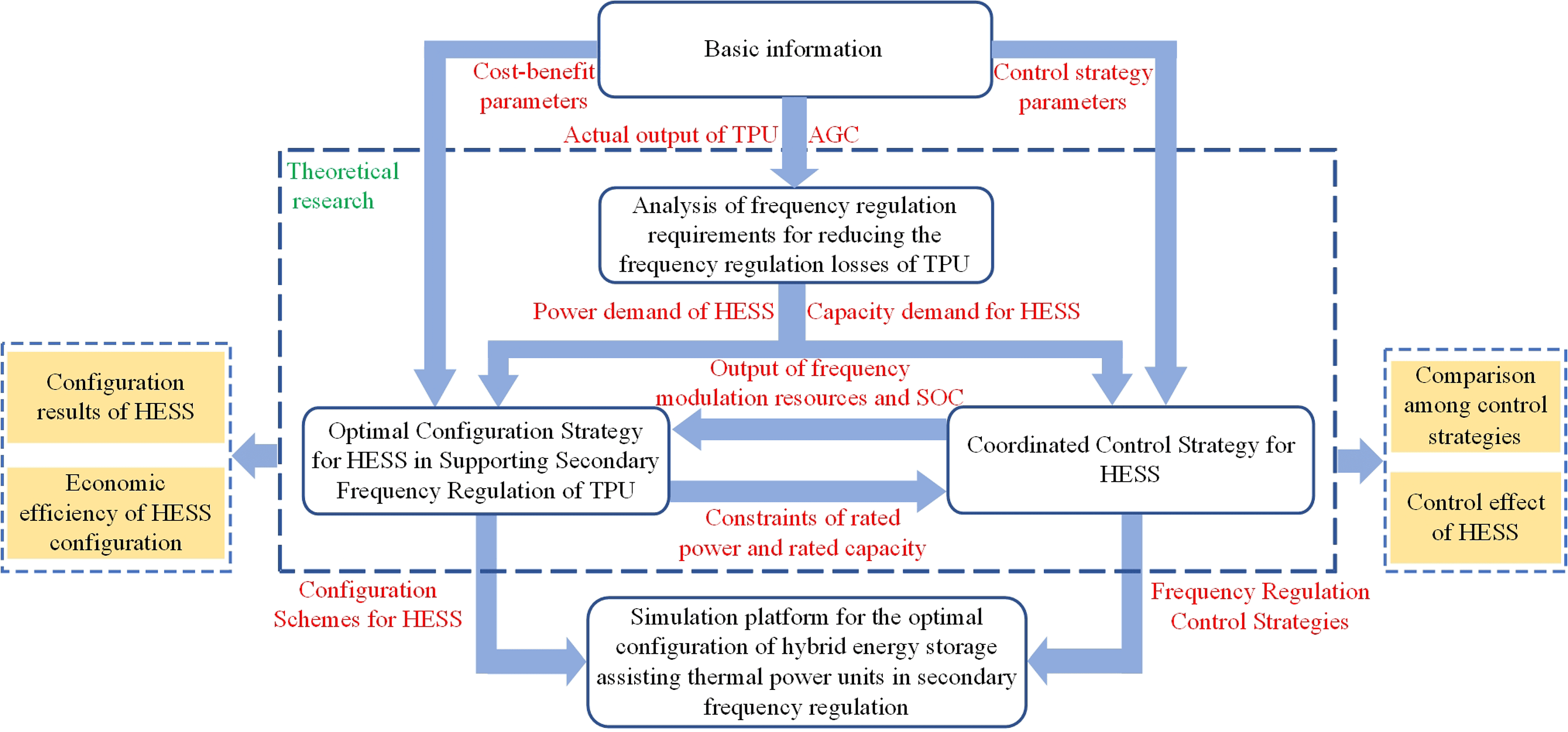
In response to the issue of determining the appropriate capacity when hybrid energy storage systems (HESS) collaborate with thermal power units (TPU) in the system’s secondary frequency regulation, a configuration method for HESS based on the analysis of frequency regulation demand analysis is proposed. And a corresponding simulation platform is developed. Firstly, a frequency modulation demand method for reducing the frequency modulation losses of TPU is proposed. Secondly, taking into comprehensive consideration that flywheel energy storage features rapid power response and battery energy storage has the characteristic of high energy density, a coordinated control strategy for HESS considering the self-recovery of state of charge (SOC) is put forward. Then, to measure the economic and technical performance of HESS in assisting the secondary frequency modulation of TPU, an optimized configuration model considering the full-life-cycle economy and frequency modulation performance of TPU and HESS system is constructed. Finally, a visual simulation platform for the combined frequency modulation of TPU and HESS is developed based on Matlab Appdesigner. The results of calculation examples indicate that the proposed configuration method can improve the overall economic efficiency and frequency modulation performance of TPU and HESS; The control strategy can not only prolong the service life of battery energy storage but also enhance the continuous response ability of HESS; The visual simulation platform is easy to use, and the simulation results are accurate and reliable.Graphic Abstract
Keywords
To address climate change and enhance energysecurity, the “14th Five-Year Plan for the Modern Energy System” proposes to facilitate the transformation of the power system to accommodate large-scale and high-proportion renewable energy integration. Additionally, it aims to accelerate the large-scale deployment of advanced energy storage technologies and promote the development of energy storage on the power generation side [1,2]. The randomness, intermittency, and volatility of renewable energy output result in significant power imbalances and frequency fluctuations within the power system [3–6]. As traditional frequency modulation resources, TPU exhibit limited start-stop capabilities and slow response speeds. In contrast, energy storage systems represent high-quality flexible frequency regulation resources. Integrating energy storage to assist TPU in frequency modulation can significantly enhance the system’s resilience to uncertainties and promote the integration of renewable energy [7–9].
Regarding the demand analysis of energy storage assisting TPU in frequency regulation, in Reference [10], the deviation of TPU in following the Automatic Generation Control (AGC) command is regarded as the frequency regulation demand for energy storage. Reference [11] proposes to allocate the AGC command to TPU and energy storage using the filtering principle, thereby reducing the power output of TPU. In Reference [12], Ensemble Empirical Mode Decomposition (EEMD) is employed to decompose the frequency regulation signal of the regional control error. Subsequently, the frequency regulation commands are allocated to energy storage and TPU based on high-frequency and low-frequency components, resulting in a more precise frequency regulation demand for energy storage.
For the power allocation strategy between HESS, Reference [13] uses low-pass filtering to allocate the HESS power demand to batteries and supercapacitors, which reduces the number of switching times for battery charging and discharging, but supercapacitors are prone to overcharge and over-discharge; Reference [14] put forward a control strategy where the supercapacitors respond preferentially, followed by the batteries. This strategy effectively reduces the degradation of the battery energy storage lifespan. Reference [15] implemented power distribution by partitioning the SOC of batteries and flywheels. This measure successfully avoided the problem of SOC going beyond the limit. Nevertheless, it did not account for the recovery of SOC, which had an impact on the lifespan of battery energy storage. All of the above-mentioned strategies took into consideration that power-type energy storage exhibits a rapid response speed, while energy-type energy storage has a relatively slower response speed. However, they failed to consider SOC recovery. As a result, during the initial stage of energy storage operation, the frequency regulation performance was satisfactory. But in the later stage, due to the relatively low SOC of the energy storage itself, it might not respond to some frequency regulation signals, thereby weakening the continuous operation ability of the energy storage system. In this study, a coordinated control strategy for HESS considering SOC self-recovery is proposed. By comprehensively taking into account the dynamic characteristics of flywheel energy storage with rapid power response and battery energy storage with high energy density, this strategy can not only extend the lifespan of battery energy storage but also improve the continuous response ability of HESS.
Regarding the configuration method for HESS to assist TPU in frequency regulation, Reference [16] put forward a capacity configuration approach for HESS that applies to a wide range of application scenarios. This approach took into account the initial investment cost of energy storage, the cost of battery replacement, and the degradation of battery lifespan. Reference [17] developed a capacity configuration model for HESS intending to maximize the average annual profit of HESS in assisting TPU during secondary frequency regulation. The particle swarm optimization algorithm was employed to determine the optimal capacity of the energy storage. In the above-mentioned studies, technical metrics were translated into economic benefits and integrated into the objective function. Nevertheless, constrained by the costs of energy storage and the economic performance of TPU, these approaches might result in an insufficient configuration of energy storage, thereby failing to enhance the frequency regulation performance effectively. In this study, a comprehensive approach has been adopted to address both the economic and technical dimensions of HESS assisting TPU in secondary frequency regulation. A multi-objective optimization configuration model for HESS has been developed, which incorporates the full life cycle economic analysis and the comprehensive frequency regulation performance index Kp. This model not only enhances the frequency regulation capabilities of TPU but also improves the economic efficiency of HESS, thereby addressing the limitation of “overemphasizing economy at the expense of performance” that is prevalent in traditional configuration methods.
As can be inferred from the above analysis, the configuration and control strategies of energy storage remain pivotal issues during the energy storage planning phase. The visualization simulation platform optimizes energy storage configuration and control strategies through data analysis, which holds substantial practical significance for the development of smart grids [18]. With the advancements in the energy internet and energy storage technologies, a solid foundation has been laid for the research on energy storage visualization simulation software. Reference [19] developed a battery energy management system in response to practical problems such as the difficulty in predicting the remaining battery life and the irrationality of energy distribution management. Reference [20] developed a blockchain-based virtual power plant energy management platform, aiming to stimulate diverse energy trading activities among residential users via renewable energy, energy storage, and flexible loads within the virtual power plant. Meanwhile, Reference [21] developed an intelligent communication platform based on low-cost Internet of Things technology, enabling an optimized energy management plan for an interactive hybrid microgrid system integrating solar photovoltaics, biogas, and battery energy storage. Most of the above-mentioned literature focuses on individual energy storage technologies, with limited exploration of hybrid energy storage technologies. Moreover, the scenarios mainly pertain to the energy management of regional power grids, and research is scarce regarding the configuration methods and control strategies of HESS in assisting thermal power units with frequency regulation. In this study, a coordinated control strategy and an optimization configuration model are integrated to develop an interactive simulation platform. This platform encompasses the entire verification process from “demand analysis to configuration optimization and subsequent strategy validation”, enabling the visualization and quantitative evaluation of the design, decision-making, and validation of the frequency modulation system. It supports functions such as simulating frequency modulation demands under multiple scenarios, comparing the economic efficiency of different configuration schemes, and dynamically debugging the control strategies of HESS. This serves as a decision-making tool for the energy storage transformation of TPU, reducing the technical barriers in the transition from theoretical research to engineering applications. Ultimately, it facilitates the dissemination of current theoretical achievements in the field of combined thermal power and energy storage frequency regulation and paves the way for further research.
The remaining sections of this paper are organized as follows: Section 2 analyses the challenges and issues in the thermal power-hybrid energy storage joint frequency regulation system. Section 3 first introduces the method for analyzing the frequency regulation demand of the energy storage system, followed by the proposal of a coordinated control strategy for hybrid energy storage and an optimal configuration approach for hybrid energy storage assisting thermal power units in secondary frequency regulation. Section 4 details the architecture of the simulation platform designed to optimize the configuration of hybrid energy storage systems assisting thermal power units in secondary frequency regulation. Section 5 validates the effectiveness of the simulation platform through case studies, providing a reference for the design of control strategies and the selection of configuration capacities for energy storage systems in practical engineering applications at thermal power plants.
2 Thermal Power and Hybrid Energy Storage Integrated Frequency Regulation System
This paper focuses on the power system integrating TPU and HESS for joint frequency regulation. The system structure is illustrated in Fig. 1. The AGC dis-patch center receives real-time data, including regional grid frequency and tie-line power, generates AGC instructions, and transmits them to the thermal power and hybrid energy storage frequency regulation control center. This center then allocates the frequency regulation instructions to the TPU and HESS. Finally, the hybrid energy storage frequency regulation control system further distributes the instructions between the battery and flywheel components.
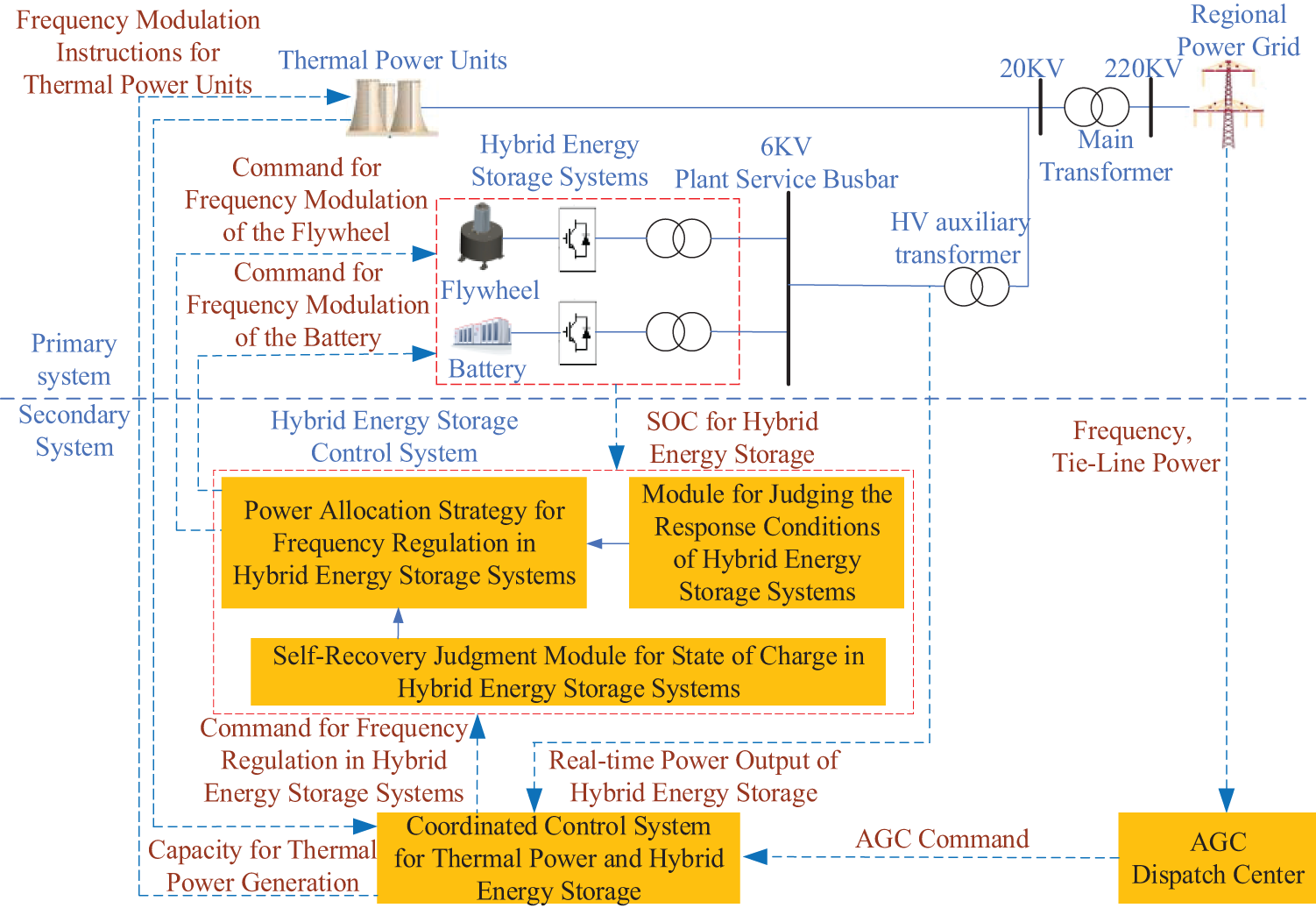
Figure 1: Thermal power and hybrid energy storage integrated frequency regulation system
The auxiliary role of HESS in the frequency regulation of TPU is becoming increasingly significant. The primary concerns currently are twofold: first, achieving optimal economic performance of the integrated thermal power and energy storage system through reasonable configuration of energy storage; second, developing effective control strategies to coordinate the output of various frequency regulation resources to achieve the best frequency regulation performance. Therefore, this paper proposes a hybrid energy storage configuration strategy based on frequency regulation demand analysis and designs a simulation platform for optimizing the configuration of HESS to assist TPU in participating in secondary frequency regulation.
3 Configuration Strategy for Hybrid Energy Storage Systems Based on Frequency Modulation Demand Analysis
Regarding the problem of how to determine the appropriate capacity when the hybrid energy storage combined with thermal power units participates in the secondary frequency regulation of the system, an optimization configuration method for hybrid energy storage based on the analysis of frequency regulation demand is proposed. The framework of the method is depicted in Fig. 2.
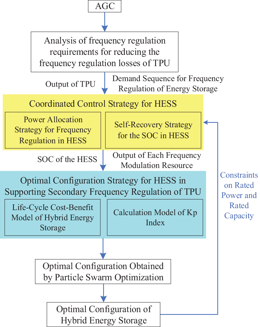
Figure 2: Methodological framework
The plant-level AGC instruction is subjected to frequency modulation demand analysis to obtain the output sequence of thermal power units and the frequency modulation demand sequence of energy storage. Secondly, the power distribution among hybrid energy storages is realized through the coordinated control strategy of HESS, and the SOC change curve of HESS is obtained. The revenue and cost within the entire life cycle and the Kp index are calculated through the configuration method to obtain the optimal configuration of HESS. Finally, the configuration values are transmitted to the control strategy as the power and capacity constraints of HESS.
3.1 Analysis of Frequency Regulation Requirements for Reducing the Frequency Regulation Losses of TPU
In this research, the frequency modulation mileage of TPU is utilized to gauge the frequency modulation loss of TPU. The output of TPU is smoothed through the filtering method to achieve the goal of reducing the frequency modulation mileage of TPU. The lower the frequency modulation mileage of TPU, the smaller the frequency modulation loss of TPU will be. Simultaneously, when smoothing the output of TPU, the actual output of TPU and the frequency modulation demand sequence of energy storage are obtained. They are classified into two scenarios: Firstly, when the actual output of TPU without energy storage configuration is known, the output of TPU is decomposed by filtering. The actual output of TPU is the low-frequency component of thermal power units without energy storage configuration, and the frequency modulation demand sequence of energy storage is the difference between the AGC command and the actual output of TPU.
Secondly, the actual output of TPU without energy storage remains uncertain. By filtering and decomposing the AGC command, we can ascertain that the actual output of this TPU represents the low-frequency component of the AGC command. Furthermore, the frequency regulation demand sequence for energy storage is derived from the difference between the AGC command and the actual output of TPU.
The demand analysis of frequency modulation provides a theoretical foundation for the sub-platform of frequency modulation demand analysis in the visual simulation platform. The AGC command and the actual output of TPU without energy storage configuration are input from the sub-platform of basic information and imported into the sub-platform of frequency modulation demand analysis to obtain the output sequence of TPU and the demand sequence for energy storage frequency modulation.
3.2 Coordinated Control Strategy for HESS
The coordinated control strategy for the HESS presented in this article is classified into the power distribution strategy for frequency modulation of the HESS and the self-recovery strategy for the SOC of HESS. This control strategy considers the preferential response of FESS and takes into account the self-recovery of the SOC of the energy storage. It can not only increase the lifespan of BESS but also improve the continuous response ability of HESS. This control strategy furnishes a theoretical foundation for the development of the sub-platform for HESS configuration and the sub-platform for feasibility analysis.
Firstly, whether to restore the SOC is determined based on the frequency regulation demand power of the HESS and the rated power of the HESS. If the SOC is not restored, the secondary frequency regulation command that the HESS needs to respond to is obtained. Subsequently, based on the SOC state of the HESS, the operating condition Sn of the HESS is determined, and the frequency regulation power of the HESS is distributed. If the SOC is not restored, the SOC self-recovery power command of the HESS is obtained. Only the TPU is involved in the frequency regulation, responding to the secondary frequency regulation command that the HESS has not responded to, enhancing the response to the AGC command. The schematic of the coordinated control strategy for the HESS is illustrated in Fig. 3.
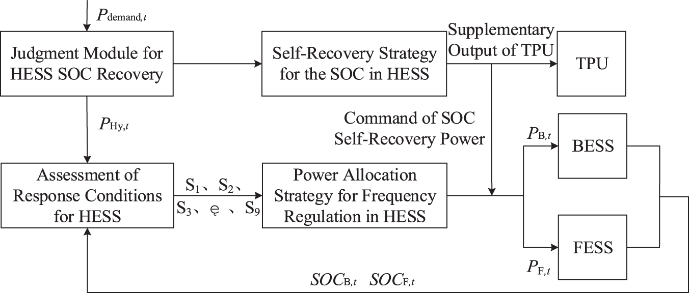
Figure 3: Coordinated control strategy for HESS
3.2.1 Power Allocation Strategy for Frequency Regulation in HESS
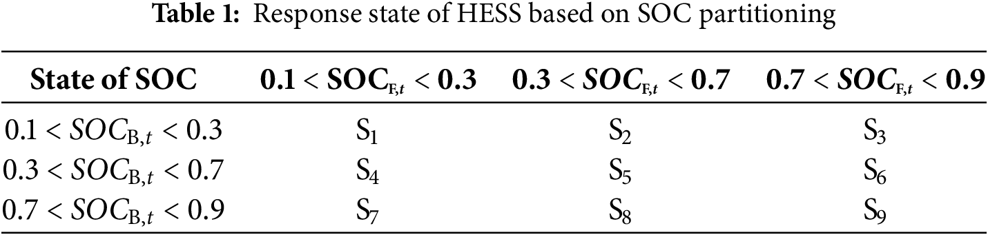
To fully leverage the advantages of each energy storage device and extend the lifespan of BESS, a frequency regulation power allocation strategy for HESS is developed based on the concept of SOC partitioning. When the SOC of FESS is within normal limits, priority in frequency regulation is given to FESS. Conversely, when the SOC of FESS becomes excessively high or low, priority shifts to BESS for frequency regulation. In scenarios where the SOC across HESS is uniformly too high or too low, a dynamic remaining SOC ratio allocation strategy is implemented to enhance responsiveness, thereby improving the continuous response capability of HESS. The various response states of this HESS based on SOC partitioning are summarized in Table 1 below. In this table, S denotes different operational conditions for HESS under varying combinations of SOCs; each condition corresponds to a specific frequency regulation power allocation strategy tailored for HESS.
(1) Charging Strategies for HESS
When the HESS operates under conditions S1, S4, S5, S7 and S8, the SOC of FESS is relatively low. In this scenario, priority is given to charging FESS, while BESS serves as a supplementary source for charging. The command for charging power in HESS is structured as follows:
When the HESS operates under conditions S2, S3 and S6, the SOC of the BESS is relatively low. In this scenario, priority is given to charging the BESS, while the FESS serves as a supplementary source for charging. The command for charging power in HESS is structured as follows:
When the HESS operates under the S9 working condition, both the BESS and FESS exhibit relatively high SOC. To enhance the overall continuous charging capacity of the HESS, a dynamic SOC proportion strategy is implemented for charging. The charging power instruction for HESS is formulated as follows:
(2) Discharge Strategies for HESS
When the HESS operates under conditions S2, S3, S5, S6 and S9, the SOC of FESS is relatively high. In this scenario, the FESS discharges preferentially while the BESS provides supplementary discharge support. The discharge power command for HESS is formulated as follows:
When the HESS operates under conditions S4, S7 and S8 the SOC of BESS is relatively high. In this scenario, the BESS discharges preferentially, while the FESS provides supplementary discharge support. The discharge power command for HESS is formulated as follows:
When the HESS operates under condition S1, the SOC for both BESS and FESS is relatively low. To enhance the overall continuous discharge capacity of HESS, a dynamic SOC ratio strategy is implemented for its discharge process. The command for discharge power in HESS is formulated as follows:
3.2.2 Self-Recovery Strategy for the SOC in HESS
When the demand for frequency regulation power from HESS exceeds its rated power, even if HESS assists the thermal power unit in frequency regulation at maximum output, the combined output of the TPU and HESS still fails to adequately track the AGC command, resulting in suboptimal regulation performance. In such cases, auxiliary frequency regulation provided by HESS may lead to unnecessary energy waste. Therefore, during periods when the maximum output power of HESS is less than or equal to its frequency regulation capacity, it is possible for the SOC of HESS to self-recover. Specifically, both battery and flywheel energy storages can charge and discharge at their rated powers to restore their SOC values to 0.5, thereby enhancing the continuous operational capability of HESS. At this stage, only TPU will participate in frequency regulation by responding solely to secondary frequency control commands that have not been addressed by HESS.
The power commands for the SOC self-recovery of BESS and FESS are presented as follows:
During the self-recovery process of HESS, the methodologies for calculating the SOC for both battery energy storage and flywheel energy storage are presented as follows:
(1) The standard deviation of SOC
To assess the recovery effect of the SOC in the HESS, a SOC standard deviation index of the energy storage system is established to measure the deviation degree between the SOC of the energy storage system and the standard SOC, as follows:
(2) Frequency modulation mileage
To assess the contribution of the hybrid energy storage to frequency modulation, an index of frequency modulation mileage for the energy storage system was constructed, as presented in the following formula:
3.3 Optimal Configuration Strategy for HESS in Supporting Secondary Frequency Regulation of TPU
This paper proposes an optimized configuration methodology for secondary frequency modulation of TPU integrated with HESS, considering both the overall economic efficiency and frequency regulation performance. It is crucial to comprehensively evaluate the cost-revenue disparity of HESS over its entire life cycle, as well as the index. The lifecycle costs include investment expenses, operation and maintenance expenditures, decommissioning and disposal fees, fault-induced loss costs, and frequency modulation costs associated with TPU. The revenues consist of AGC frequency modulation mileage income, indirect benefits from reduced coal consumption costs, and indirect benefits from decreased pollution discharge costs in the power generation system. The index comprises regulation rate metrics, regulation accuracy metrics, and response time metrics, this optimization configuration approach offers a theoretical foundation for the development of the sub-platform for hybrid energy storage configuration.
3.3.1 The Optimal Configuration Model of HESS Assisting the Secondary Frequency Regulation of TPU
The objective functions are respectively the minimization of the difference between the cost and the benefit of HESS throughout its entire life cycle and the
The calculation formula of
(1) The cost throughout the entire life cycle of HESS
① The investment cost of HESS
The investment cost of HESS includes both the initial capital expenditure for the HESS and the replacement cost of BESS. The replacement cost refers to the expenses incurred for replacing the BESS equipment over the entire life cycle. Assuming a 20-year life cycle in this study, as the lifespan of FESS typically exceeds 20 years, only the replacement cost of BESS is considered.
Let DOD denote the depth of charge and discharge of the battery, and let
To facilitate the computation of cycle numbers under varying charge and discharge depths, we define the equivalent charge and discharge coefficient
The depth of charge and discharge of the battery at each frequency modulation stage on a given day is statistically analyzed using the rain-flow counting method. By integrating this analysis with the aforementioned equation, the equivalent number of charge and discharge cycles for that day can be determined as follows:
Therefore, the operational lifespan of BESS can be determined as follows:
② The operating cost of HESS
The operating cost of HESS encompasses both power maintenance costs and energy maintenance costs.
③ The cost of asset scrapping and disposal for energy storage
FESS is a form of physical energy storage, whereas BESS involves electrochemical processes and requires recycling and end-of-life treatment. Consequently, only BESS incurs costs associated with scrapping and disposal.
④ The cost of failure losses in energy storage
The cost of energy storage failure loss comprises the cost of failure treatment and the cost of power outage loss.
⑤ The frequency modulation cost of TPU
The frequency regulation cost of TPU consists of the frequency regulation loss and wear resulting from the inherent performance of TPU during the frequency regulation process, and the penalty cost for frequency regulation deviation electricity.
where
(2) The earnings of HESS within the entire life cycle
① The revenue from AGC frequency modulation mileage
When TPU participates in AGC regulation services, leading to increased coal consumption costs, the market provides economic compensation to AGC units to offset these additional expenses.
② The indirect benefits of coal consumption reduction
The frequency regulation of TPU assisted by energy storage will lead to a reduction in the output of TPU, thereby cutting down the fuel cost of TPU.
③ Environmental benefits
With the reduction in the output of TPU, the corresponding decrease in greenhouse gas emissions can be quantified as an environmental benefit. The formula for calculating this benefit is as follows:
(1) Power balance restriction
(2) Constraint on the rated power of HESS
(3) SOC Constraints of HESS
3.4 The Solution Process of the Optimization Configuration Method
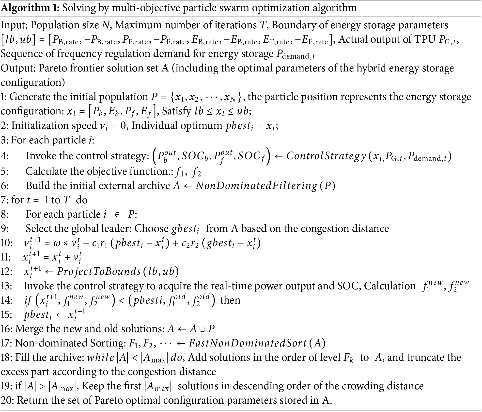
In this scholarly work, the developed HESS optimization configuration model is solved utilizing the multi-objective particle swarm optimization algorithm. The AGC instructions and the output of TPU, among other fundamental information, are processed through the frequency regulation demand methodology outlined in Section 3.1 to derive the actual output of TPU and the sequence of energy storage frequency regulation demands. Parameters such as the population size and the number of iterations for the multi-objective particle swarm optimization algorithm are set, and the velocities and positions of each particle are initialized. Each particle’s coordinates represent the rated power capacity of HESS. By substituting these into the HESS coordinated control strategy, the real-time output and SOC state of HESS are obtained. These values are then substituted into the optimization configuration model to solve the multi-objective optimization function, updating the global best value
4 Development of a Simulation Platform for Optimal Configuration of HESS to Support TPU in System Secondary Frequency Regulation
4.1 More Aligned with Academic Contexts
Based on the requirements for frequency modulation, a coordinated control strategy has been developed for HESS, along with an optimal configuration approach to assist TPU in secondary frequency modulation. This has led to the creation of a visualization simulation platform designed for optimizing the combined frequency modulation of thermal power and energy storage. The framework of this simulation platform is illustrated in Fig. 4.
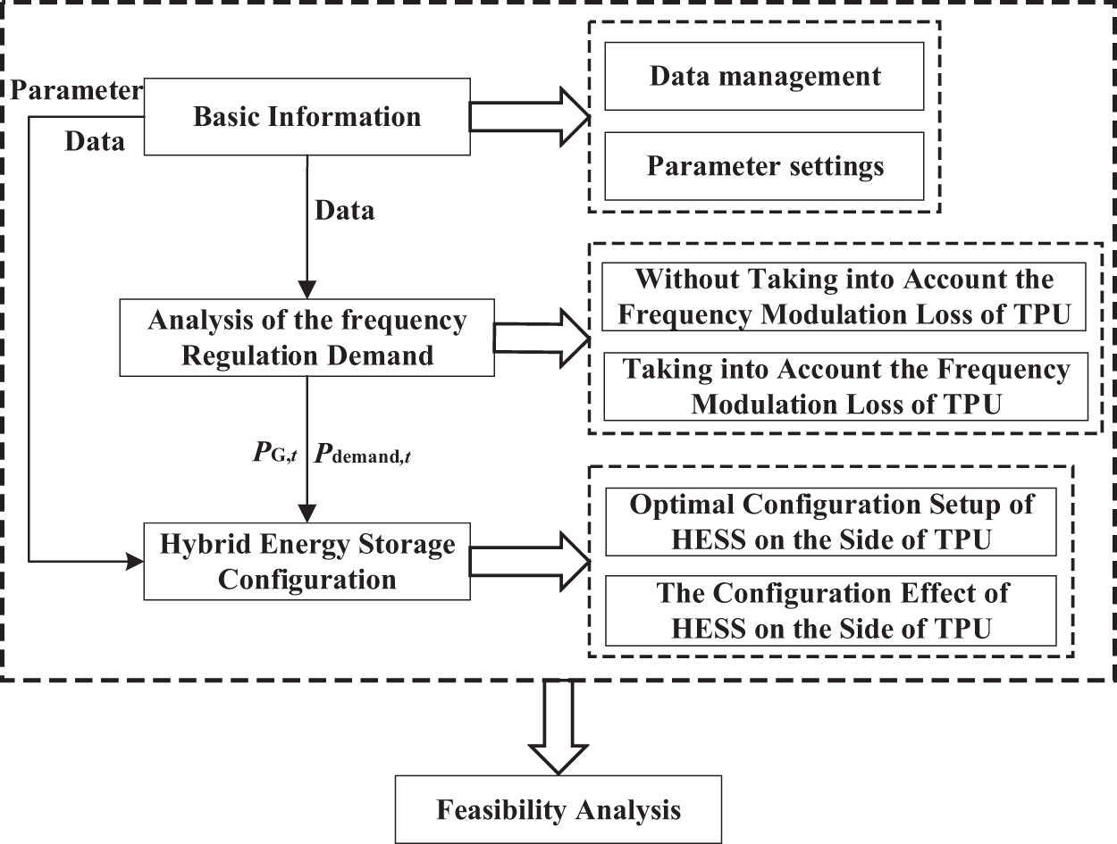
Figure 4: Overall architectural framework
Part 1 provides basic information, including AGC, the management of actual output in TPU, the parameter settings for cost and benefit analysis of energy storage configurations, and the parameter settings related to control strategies.
Part 2 presents an analysis of the frequency regulation demand for TPU supported by energy storage systems. This section examines the frequency regulation requirements with a focus on minimizing the frequency regulation losses associated with TPU. It provides both the output sequence of this TPU and the corresponding frequency regulation demand sequence for energy storage, which will be utilized in Part 3.
Part 3 focuses on the HESS configuration, encompassing both the optimal arrangement of HESS on the thermal power side and the impact of this configuration on TPU.
Part 4 presents the feasibility analysis. Building upon the insights gained from the preceding three sections, a comprehensive feasibility assessment of the HESS configuration scheme is conducted. This section also details the data output and report generation associated with the proposed configuration scheme.
4.2 Design and Functional Specification of Sub-Platforms
4.2.1 Basic Information Sub-Platform
This sub-platform includes AGC instructions, the management of TPU outputs, parameter settings for the cost-benefit analysis of energy storage configurations, and parameter settings for the coordinated control strategy of HESS. The structure is illustrated in Fig. 5. In the data management sub-module, AGC instructions and thermal power data are imported and displayed by selecting a specific date and determining an appropriate sampling interval. In the parameter setting sub-module, parameters related to both the cost-benefit analysis of energy storage configurations and those about the coordinated control strategy of HESS are inputted.
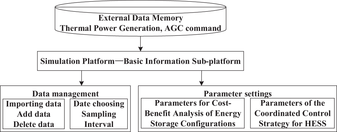
Figure 5: Architectural structure of the basic information sub-platform
4.2.2 Frequency Modulation Demand Analysis Sub-Platform
This sub-platform evaluates the impact of frequency modulation losses from TPU on the frequency modulation demand for energy storage. Utilizing the established frequency modulation demand calculation methodology, it employs the difference method to compute the frequency modulation demand without accounting for TPU losses and the filtering method to calculate the demand when these losses are considered. The analysis of frequency modulation losses includes scenarios where actual output data from TPU are available as well as cases based solely on the frequency modulation response models of these units. The frequency modulation demand analysis sub-platform primarily processes and analyses data from the basic information sub-platform to derive the sequence of frequency modulation demand for energy storage. Additionally, it can generate various statistical characteristics of the analyzed data. The structure is illustrated in Fig. 6.
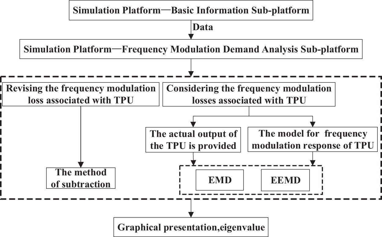
Figure 6: Architectural structure of the frequency modulation demand analysis sub-platform
4.2.3 Hybrid Energy Storage Configuration Sub-Platform
This sub-platform is grounded in the hybrid energy storage coordinated control strategy and the optimized configuration method for HESS assisting TPU in frequency modulation, as proposed in this study. It leverages parameters from the basic information sub-platform and integrates the output of TPU and the frequency modulation demand sequence provided by the frequency modulation demand sub-platform. By employing intelligent optimization algorithms, it determines the optimal configuration of HESS on the TPU side. Additionally, it presents the energy storage status, evaluates the economic efficiency of the hybrid energy storage configuration, and provides a detailed breakdown of cost proportions over the entire life cycle. The structure is illustrated in Fig. 7.
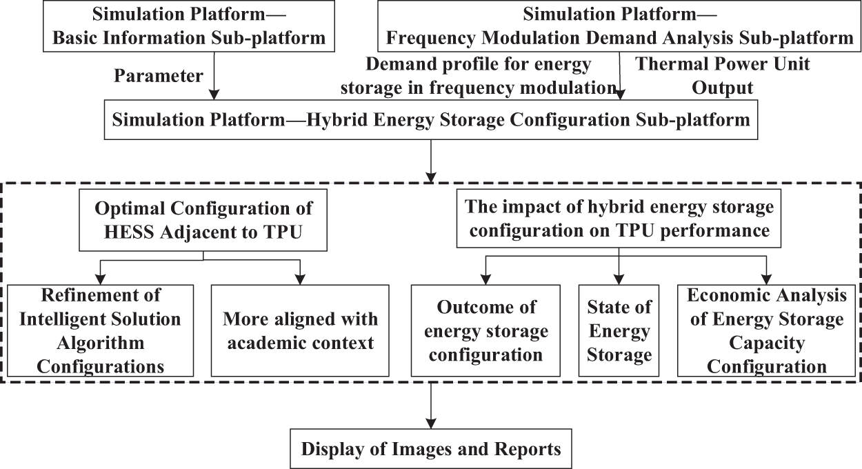
Figure 7: Architectural structure of the hybrid energy storage configuration sub-platform
4.2.4 Feasibility Analysis Sub-Platform
This sub-platform, built upon the optimized configuration outcomes of the hybrid energy storage configuration sub-platform, is designed to conduct comparative analyses of various control strategies under identical configurations. It evaluates factors such as net income, SOC conditions, battery lifespan, and frequency regulation capabilities for thermal storage across different control strategies. The results of these evaluations are presented and can be exported in the format of technical assessment schematic diagrams and performance comparison tables, as illustrated in Fig. 8.
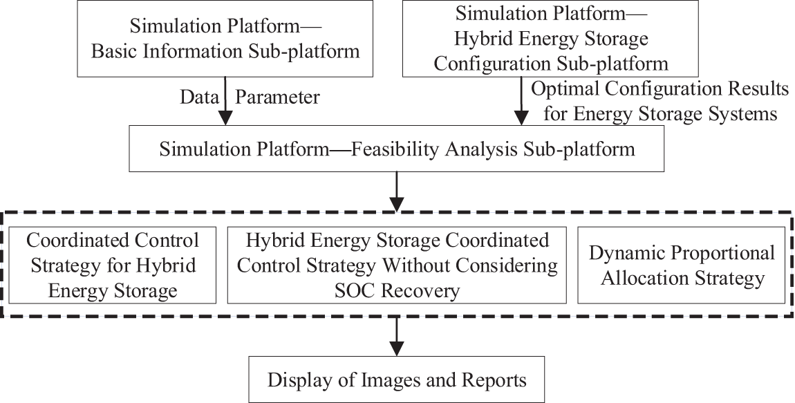
Figure 8: Architectural structure of the feasibility analysis sub-platform
5 Verification of the Simulation Platform
5.1 Computational Example Conditions
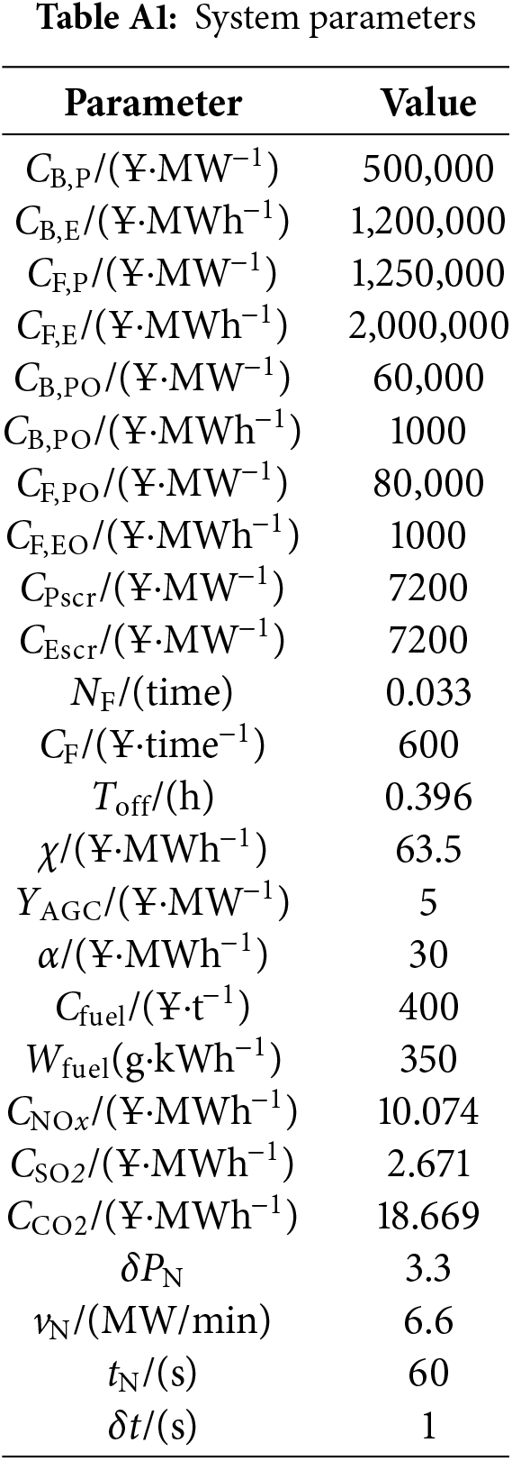
To validate the effectiveness of the simulation platform, this case study utilizes the measured data from a 330 MW TPU in a specific domestic location on the fifth day for analysis. The system parameters are detailed in Table A1 of Appendix B [22,23].
5.2 Validation of the Functional Capabilities of the Simulation Platform
5.2.1 Realization of the Functional Capabilities of the Basic Information Sub-Platform
In the context of the data management module, clicking the “Import Data” button facilitates the import of AGC instructions and thermal power output in various formats. The “Add” button allows for incremental data imports on top of the existing dataset. The “Delete” button enables the removal of selected data entries via mouse selection. Data visualization presents the AGC instructions and thermal power output corresponding to the selected date. As illustrated in Fig. 9.
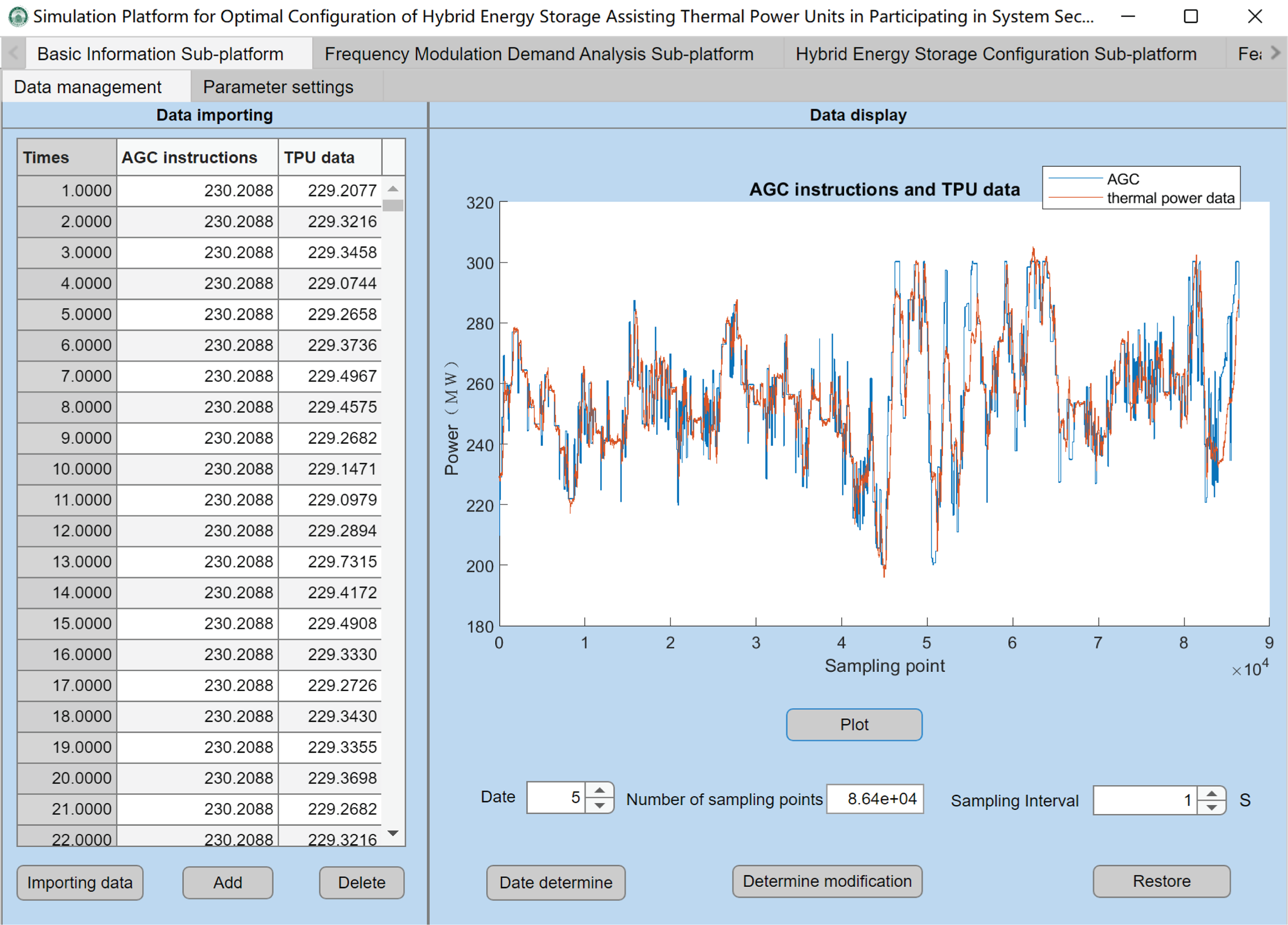
Figure 9: Simulation of the basic information sub-platform
5.2.2 Realization of the Functional Capabilities of the Frequency Modulation Demand Analysis Sub-Platform
When calculating the frequency regulation demand without accounting for the reduction in thermal power frequency regulation losses, clicking the “Confirm” button displays the AGC characteristic values, thermal power output characteristics, and the corresponding frequency regulation demand. Additionally, the frequency regulation demand for a specific time interval within a day can be computed by adjusting the start and end sampling points. As illustrated in Fig. 10, when thermal power frequency regulation losses are not considered, the required energy storage power is 32.6 MW and the required energy storage capacity is 33.09 MWh.
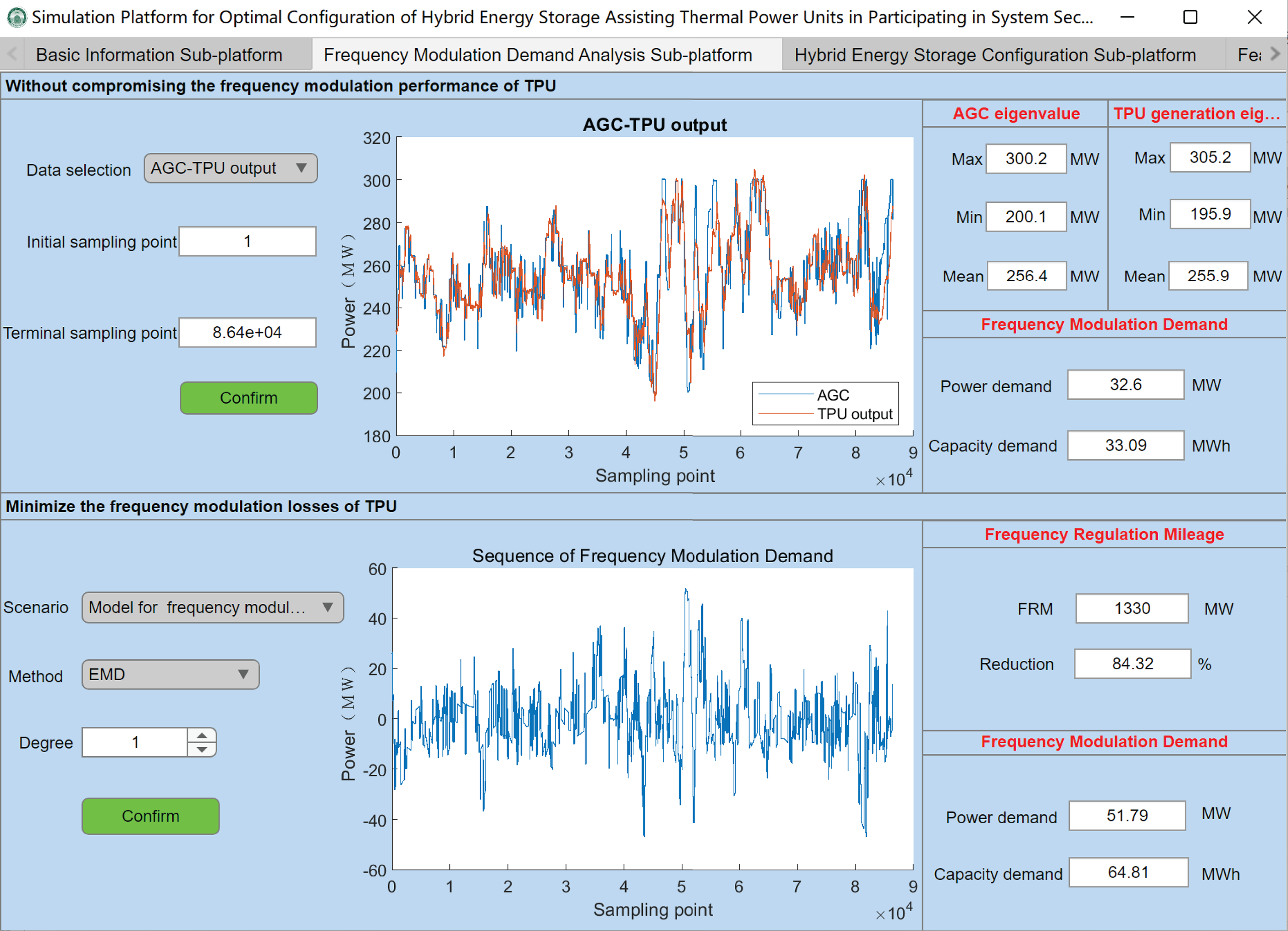
Figure 10: Simulation of the frequency modulation demand analysis sub-platform
When calculating the frequency regulation demand while accounting for the reduction in TPU frequency regulation losses, the frequency regulation mileage of TPU is used as a metric to quantify these losses. Scenarios based on the actual output of known TPU are selected, and the EMD method is employed. By adjusting the order of EMD, the frequency regulation mileage of TPU is minimized to obtain the corresponding frequency regulation demand. As illustrated in Fig. 10, when the frequency regulation mileage decreases by 84.32%, the frequency regulation capacity of the thermal power unit is 1330 MW, the required power for energy storage is 51.79 MW, and the required energy storage capacity is 64.81 MWh.
5.2.3 Realization of the Functional Capabilities of the Hybrid Energy Storage Configuration Sub-Platform
In the hybrid energy storage configuration sub-platform, the battery and flywheel hybrid energy storage configuration scheme are selected. The parameters of the PSO model are configured. Based on the previously described optimization approach for HESS assisting TPU in secondary frequency regulation and the specified case conditions, clicking the “Start” button yields the HESS configuration results, economic performance metrics, and the output and SOC status of the energy storage systems. As illustrated in Fig. 11, the rated power of the lithium-ion battery is 15.35 MW, the rated capacity is 26.46 MWh, the rated power of the flywheel is 28 MW, the rated capacity is 28 MWh, the net income is 2.41 billion yuan, and the Kp is 6.66.
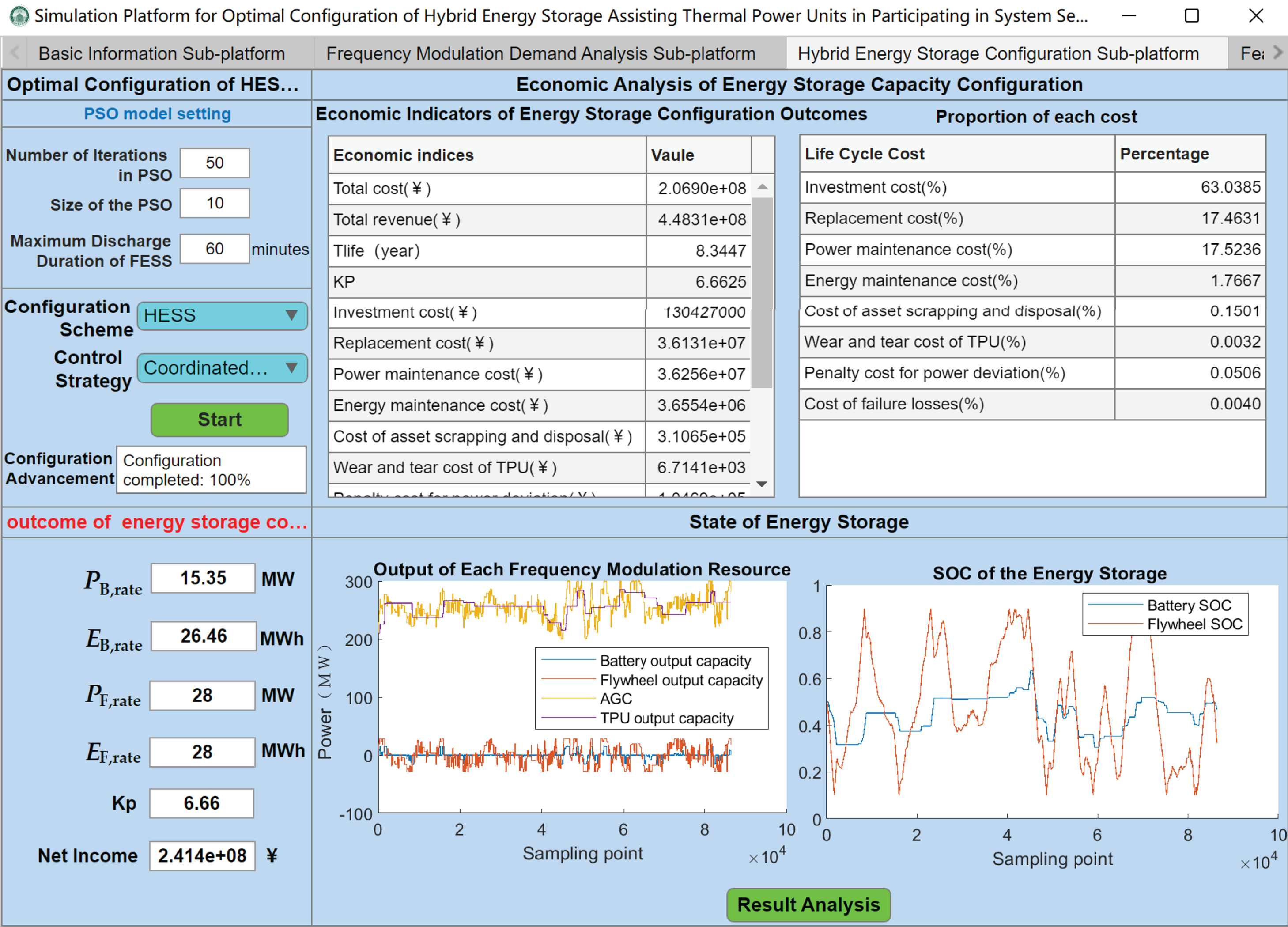
Figure 11: Simulation of the hybrid energy storage configuration sub-platform
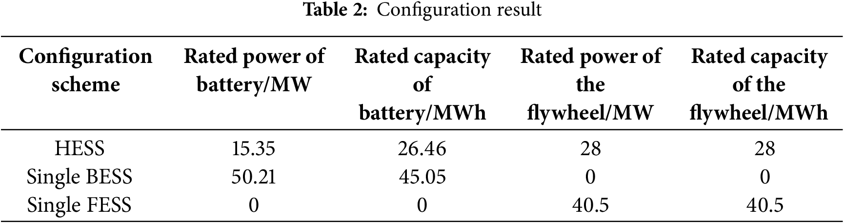
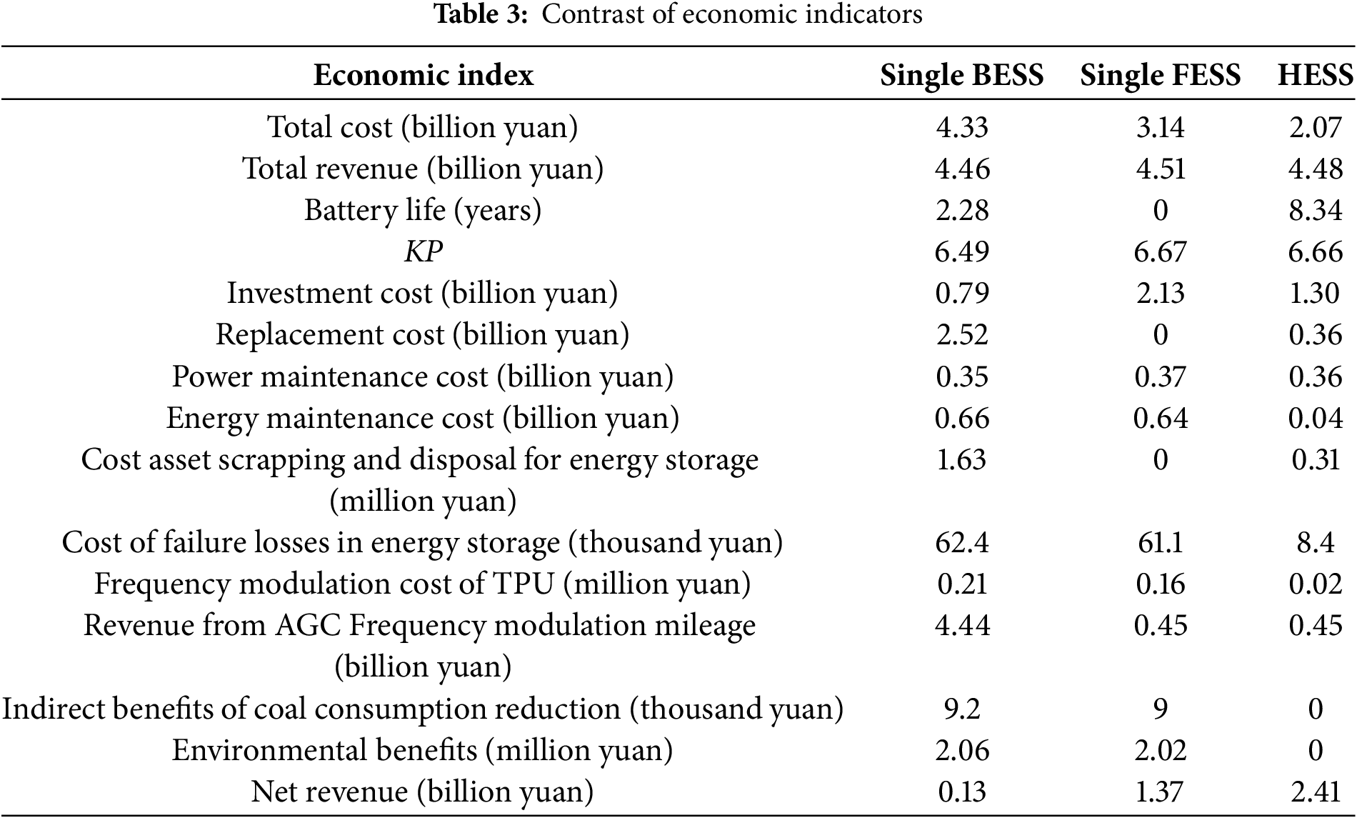
This sub-platform is also capable of operating other configuration schemes. The configuration outcomes and economic indicators of all configuration schemes are presented in Tables 2 and 3 as follows: When a single battery is configured, the replacement cost of the battery constitutes 58.21% of the total cost of frequency modulation throughout the entire lifespan. Compared with the single battery configuration, the lifespan of lithium batteries in the HESS configuration is increased by approximately 2.66 times, effectively reducing the replacement cost of the battery [24]. When a single flywheel is configured, the initial investment cost accounts for 67.67% of the total cost of frequency modulation throughout the entire lifespan. The lower investment cost of lithium batteries in the HESS configuration leads to a reduction of 1.07 billion yuan in the total cost compared with the single flywheel configuration. This demonstrates that this configuration method effectively enhances the economic performance of the HESS.
5.2.4 Realization of the Functional Capabilities of the Feasibility Analysis Sub-Platform
Based on the optimized configuration results obtained from the hybrid energy storage configuration sub-platform, clicking the “Draw Graph and Generate Report” button allows for a comparative analysis of the performance of different control strategies, as illustrated in Fig. 12. Strategy 1 represents the proposed method in this study; Strategy 2 is identical to Strategy 1 but does not consider the self-recovery of the SOC of the HESS; Strategy 3 employs a dynamic SOC proportion allocation approach among the HESS and incorporates the self-recovery of the SOC.
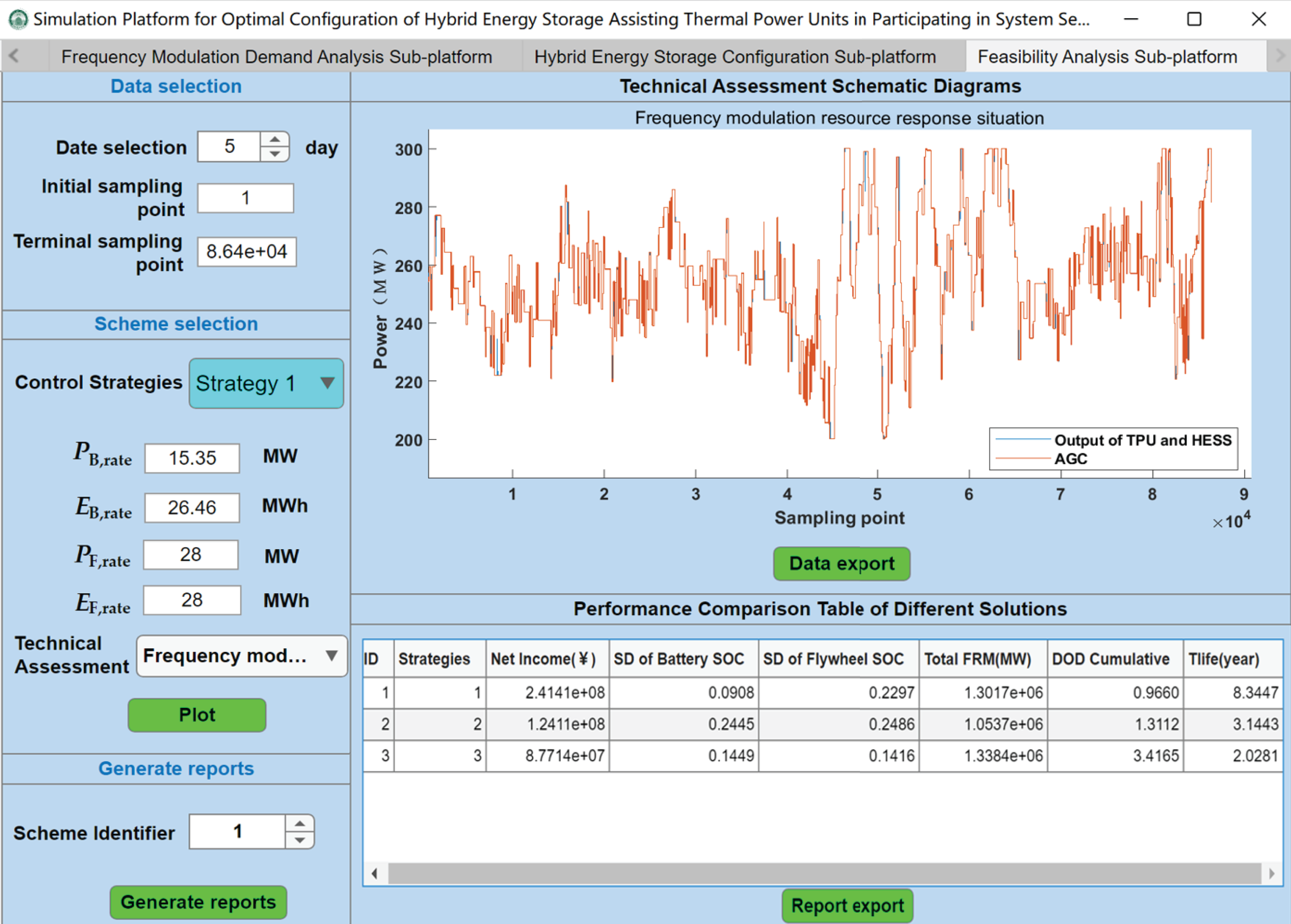
Figure 12: Simulation of the feasibility analysis sub-platform
As illustrated in the figure above, under Strategy 1, the standard deviation of the battery SOC is 0.0908, and that of the flywheel SOC is 0.2297; under Strategy 2, the standard deviations are 0.2445 for the battery and 0.2486 for the flywheel; under Strategy 3, the standard deviations are 0.1449 for the battery and 0.1416 for the flywheel. Strategies 1 and 3 incorporate the self-recovery mechanism of hybrid energy storage SOC, leading to better maintenance of both battery and flywheel SOC levels, thereby enhancing the continuous operation capability of HESS. In contrast, Strategy 2 exhibits a lower total frequency regulation mileage compared to Strategies 1 and 3. This is attributed to the absence of SOC self-recovery in Strategy 2, which results in significant declines in the SOC levels of both the flywheel and battery during the later stages of frequency regulation. Consequently, this leads to reduced frequency regulation mileage and diminished continuous operation capability of HESS.
Under Strategy 1, when the SOC of the flywheel energy storage is within normal or high ranges, the flywheel energy storage responds with priority, while the battery compensates for any power deficiencies. This results in a relatively low DOD cumulative for the battery, thereby extending its service life. In contrast, Strategy 3 employs proportional power distribution between the battery and flywheel based on their real-time SOC levels. Under this strategy, the DOD cumulative of the battery is significantly higher, leading to a substantially greater loss in battery service life compared to Strategy 1. Specifically, the battery service life under Strategy 1 is 3.11 times longer than that under Strategy 3.
This paper proposes a coordinated control strategy for HESS and develops an optimization configuration method for secondary frequency regulation of TPU assisted by HESS. The proposed method aims to minimize the full life-cycle cost of energy storage while enhancing the system’s frequency regulation performance. Based on this optimization approach and utilizing Matlab Appdesigner, a visualization simulation platform has been developed for the optimal configuration and coordinated control of thermal power and energy storage units in frequency regulation applications. The case study employs actual operational data from a 330 MW TPU in North China to validate the effectiveness of the visualization simulation platform. Simulation results demonstrate that the platform can manage data efficiently, conduct demand analysis for energy storage frequency regulation, achieve optimal hybrid energy storage configuration through intelligent algorithms, and perform feasibility studies. The platform is user-friendly, and its configuration results are accurate and reliable.
Acknowledgement: I would like to express my heartfelt gratitude to the other authors for their invaluable contributions and assistance in this research work.
Funding Statement: This work was supported by a Key Project of the National Natural Science Foundation of China under Grant 52337004.
Author Contributions: The authors confirm their contribution to the paper as follows: Cuiping Li: Writing—original draft, methodology, conceptualization. Ziyun Zong: Writing—original draft, software, methodology, formal analysis. Xingxu Zhu: Software, formal analysis. Zheng Fang: Data curation, investigation. Caiqi Jia: Methodology, conceptualization. Wenbo Si: Methodology, conceptualization. Gangui Yan: Validation, formal analysis. Junhui Li: Writing—review & editing, methodology, conceptualization.
Availability of Data and Materials: The authors ensure the authenticity and validity of the materials and data in the article.
Ethics Approval: Not applicable.
Conflicts of Interest: The authors declare no conflicts of interest to report regarding the present study.
Glossary
| PAGC,t | AGC instruction at time t |
| Low-frequency component of the actual output of the thermal power unit without energy storage configuration at time t | |
| Actual output of the thermal power unit at time t | |
| Sequence of frequency regulation demand for energy storage at time t | |
| Low-frequency component of the AGC command | |
| The actual output of battery energy storage at the moment t | |
| The actual output of the flywheel energy storage at the moment t | |
| Rated power of battery energy storage | |
| Rated power of flywheel energy storage | |
| Actual output of hybrid energy storage system | |
| The SOC of battery energy storage at the moment t | |
| The SOC of flywheel energy storage at the moment t | |
| Self-recovery power command of battery energy storage SOC at time t | |
| Self-recovery power command of flywheel energy storage SOC at time t | |
| Rated capacity of battery energy storage | |
| Rated capacity of flywheel energy storage | |
| Charge and Discharge efficiency of battery energy storage | |
| Charge and Discharge efficiency of flywheel energy storage | |
| Single control time | |
| Standard deviation of the SOC of the energy storage system j | |
| Standard SOC | |
| M | Total control period |
| Frequency modulation mileage of energy storage system j | |
| Frequency modulation power of energy storage system j at time t | |
| Cinv | The investment cost of HESS |
| COM | The operating cost of HESS |
| Cscr | The cost of asset scrapping and disposal for energy storage |
| CF | The cost of failure losses in energy storage |
| CTF | The revenue from AGC frequency modulation mileage |
| Bkp | The revenue from AGC frequency modulation mileage |
| Bcoal | The indirect benefits of coal consumption reduction |
| Benv | Environmental benefits |
| K1 | Regulation rate indicator |
| K2 | Regulation accuracy indicator |
| K3 | Response time indicator |
| CB,P | The cost per unit power of battery energy storage |
| CF,P | The cost per unit power of flywheel energy storage |
| CB,E | The cost per unit capacity of battery energy storage |
| CF,E | The cost per unit capacity of flywheel energy storage |
| R | The discount rate |
| TLCC | Entire life cycle |
| N | Replacement frequency |
| Tlife | Battery lifespan |
| DBESS | The charge-discharge depth of the battery |
| NC | Number of charge-discharge cycles |
| DBESS,i | The depth of charge-discharge for the i-th cycle |
| DBESS,R | Rated charge and discharge depth |
| NR | The maximum number of charge-discharge cycles of the battery at the rated depth of charge-discharge |
| Equivalent charge and discharge coefficient | |
| The maximum number of charge-discharge cycles in the case of full charge and discharge | |
| CB,PO | The operation and maintenance cost per unit power of the battery |
| CF,PO | The operation and maintenance cost per unit power of the flywheel |
| CB,EO | The operation and maintenance cost per unit of energy of the battery |
| CF,EO | The operation and maintenance cost per unit of energy of the flywheel |
| WB(t) | The annual charge-discharge quantity of the battery |
| WF(t) | The annual charge-discharge quantity of the flywheel |
| CB, Pscr | The cost of waste disposal per unit power of batteries |
| CB, Escr | The cost of battery scrap disposal per unit of energy |
| NF | Annual average failure frequency of energy storage equipment |
| CF | Average cost of fault treatment |
| Toff | The annual average outage duration of energy storage devices |
| e(t) | The electricity price of the energy storage ancillary service market in the t-th year |
| W(t) | The charge and discharge electricity of energy storage in the t-th year |
| χ | The cost of unit ramping loss |
| Emar | Annual deviation of electricity volume |
| Α | Penalization coefficient |
| YAGC | The price of AGC compensation |
| Et | The frequency regulation discharge volume of energy storage on the same day |
| Cfuel | Unit price of fuel |
| Wfuel | The fuel quantity required per unit of electricity generation |
| CNOx | The emission cost of nitrogen oxides required per unit of electricity generation |
| CSO2 | The emission cost of sulfur dioxide required per unit of electricity generation |
| CCO2 | The emission cost of carbon dioxide required per unit of electricity generation |
| The lower limit of the SOC of battery energy storage | |
| The upper limit of the SOC of battery energy storage | |
| The lower limit of the SOC of flywheel energy storage | |
| The upper limit of the SOC of flywheel energy storage | |
| vi | The regulation rate of the thermal power unit during the i-th regulation |
| P1 | The output of the TPU at the time when the AGC command is updated at the current moment |
| The regulating dead zone of TPU | |
| The regulation dead zone of AGC command | |
| vN | The standard regulation rate of the TPU |
| δPi | The regulation deviation of the TPU during the i-th adjustment period |
| δPN | The permissible regulation deviation of the TPU |
| ti | Response time of the TPU for the i-th regulation |
| tN | Standard response time of the TPU |
It can be inferred from the “Two Rules” governing grid-connected power plants in the North China region that the frequency modulation performance of thermal power units, following the execution of a single AGC command, is assessed using the Kp index. Fig. A1 illustrates the typical AGC response process for a specific unit within the grid. The calculation method for determining the comprehensive frequency modulation performance index Kp is outlined as follows.
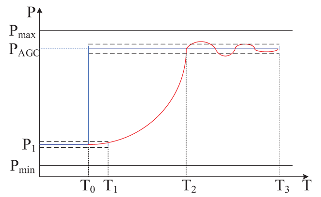
Figure A1: Typical AGC response process of thermal power units
(1) Regulation rate
The regulation rate, which represents the ramping stage of the thermal power unit’s response to the AGC command as shown in the T1–T2 interval, is calculated using the following formula:
(2) Regulatory precision
The regulatory precision corresponds to the stable stage of the thermal power unit’s response to the AGC command, as depicted in the T2–T3 interval in Fig. A1. During this phase, the unit’s output has exceeded the AGC command deadband. The evaluation focuses on the regulation deviation during this period, and the calculation formula is:
(3) Response time
The response time corresponds to the initial response stage of the thermal power unit to the AGC command, as depicted in the T0–T1 interval in Fig. A1. The formula for calculating the actual response time is as follows:
References
1. Hong F, Zhao Y, Ji W, Hao J, Fang F, Liu J. A dynamic migration route planning optimization strategy based on real-time energy state observation considering flexibility and energy efficiency of thermal power unit. Appl Energy. 2025;377(13):124575. doi:10.1016/j.apenergy.2024.124575. [Google Scholar] [CrossRef]
2. Li J, Zhang Y, Chen C, Wang X, Shao Y, Zhu X, et al. Two-stage planning of distributed power supply and energy storage capacity considering hierarchical partition control of distribution network with source-load-storage. Energy Eng. 2024;121(9):2389–408. doi:10.32604/ee.2024.050239. [Google Scholar] [CrossRef]
3. Hao H, Qiu H, Zhang Y, Wang C, Nyakilla EE, Yang N, et al. Recent advancements in the optimization capacity configuration and coordination operation strategy of wind-solar hybrid storage system. Energy Eng. 2025;122(1):285–306. doi:10.32604/ee.2024.057720. [Google Scholar] [CrossRef]
4. Wang Y, Ma Z, Zhang J, Zhou Q, Zhang R, Dong H. Optimal configuration method for the installed capacity of the solar-thermal power stations. Energy Eng. 2023;120(4):949–63. doi:10.32604/ee.2023.025668. [Google Scholar] [CrossRef]
5. Ye X, Tan F, Song X, Dai H, Li X, Mu S, et al. Modeling, simulation, and risk analysis of battery energy storage systems in new energy grid integration scenarios. Energy Eng. 2024;121(12):3689–710. doi:10.32604/ee.2024.055200. [Google Scholar] [CrossRef]
6. Manjula A, Kute UT, Reddy CVK, Mallala B. Power quality improvement of microgrid for photovoltaic ev charging station with hybrid energy storage system using RPO-ADGAN approach. J Energy Storage. 2025;108(5):114970. doi:10.1016/j.est.2024.114970. [Google Scholar] [CrossRef]
7. Yan G, Sha Q, Li J, Fang Z, Lv S, Zhan S, et al. Coordinated frequency regulation for thermal power unit and battery energy storage using dynamic proportional control. Int J Electr Power Energy Syst. 2025;168(05):110724. doi:10.1016/j.ijepes.2025.110724. [Google Scholar] [CrossRef]
8. Lv Y, Sun H, Wu B, Shi Y, Fang F. Research on frequency modulation of thermal power units combined with compressed air energy storage based on model predictive control. Int J Electr Power Energy Syst. 2025;168(4):110646. doi:10.1016/j.ijepes.2025.110646. [Google Scholar] [CrossRef]
9. Zhou J, Zhang L, Zhu L, Zhang W. A data-driven operating improvement method for the thermal power unit with frequent load changes. Appl Energy. 2024;354:122195. doi:10.1016/j.apenergy.2023.122195. [Google Scholar] [CrossRef]
10. Xie X, Guo Y, Wang B, Dong Y, Mou L, Xue F. Improving AGC performance of coal-fueled thermal generators using multi-MW scale BESS: a practical application. IEEE Trans Smart Grid. 2018;9(3):1769–77. doi:10.1109/TSG.2016.2599579. [Google Scholar] [CrossRef]
11. Liu X, Xu X, Wu Q, Chen X, Wen J, Wang W, et al. SoC threshold optimization for battery storage in frequency regulation considering uncertainty of SoC measurement and automatic generation control fatigue loss of thermal power system. Int J Electr Power Energy Syst. 2022;137(8):107771. doi:10.1016/j.ijepes.2021.107771. [Google Scholar] [CrossRef]
12. Li CP, B. SW, Li JH, Yan GG, Jia C. Two-layer optimization of frequency modulated power of thermal generation and multi-storage system based on ensemble empirical mode decomposition and multi-objective genetic algorithm. Trans China Electrotech Soc. 2023;39(7):2017–32. (In Chinese). doi:10.19595/j.cnki.1000-6753.tces.230186. [Google Scholar] [CrossRef]
13. Elwakil MM, El Zoghaby HM, Sharaf SM, Mosa MA. Adaptive virtual synchronous generator control using optimized Bang-Bang for Islanded microgrid stability improvement. Prot Control Mod Power Syst. 2023;8(1):57. doi:10.1186/s41601-023-00333-7. [Google Scholar] [CrossRef]
14. Wilberforce T, Anser A, Swamy JA, Opoku R. An investigation into hybrid energy storage system control and power distribution for hybrid electric vehicles. Energy. 2023;279(16):127804. doi:10.1016/j.energy.2023.127804. [Google Scholar] [CrossRef]
15. Zhu Y, Liu J, Zeng D, Liang L, Xie Y, Li R, et al. Energy management strategy and operation strategy of hybrid energy storage system to improve AGC performance of thermal power units. J Energy Storage. 2024;102:114191. doi:10.1016/j.est.2024.114191. [Google Scholar] [CrossRef]
16. Masih-Tehrani M, Ha’iri-Yazdi MR, Esfahanian V, Safaei A. Optimum sizing and optimum energy management of a hybrid energy storage system for lithium battery life improvement. J Power Sources. 2013;244:2–10. doi:10.1016/j.jpowsour.2013.04.154. [Google Scholar] [CrossRef]
17. Xie DQ, Xu YH, Li HQ, Jia XY, Liang L, Hong F. Optimizing capacity configuration of hybrid energy storage for assistant AGC frequency regulation of thermal power units. Electr Eng. 2023;19:15–8. (In Chinese). doi:10.19768/j.cnki.dgjs.2023.19.005. [Google Scholar] [CrossRef]
18. Lin Y, Luo H, Chen Y, Yang Q, Zhou J, Chen X. Enhancing participation of widespread distributed energy storage systems in frequency regulation through partitioning-based control. Prot Control Mod Power Syst. 2025;10(1):76–89. doi:10.23919/pcmp.2023.000164. [Google Scholar] [CrossRef]
19. Zeng L, Fu J, Sheng C, Li B, Guo Z, Xiang Q, et al. Energy management for proton exchange membrane fuel cell-lithium battery hybrid power systems based on real-time prediction and optimization under multimodal information. J Clean Prod. 2024;434(78):140225. doi:10.1016/j.jclepro.2023.140225. [Google Scholar] [CrossRef]
20. Yang Q, Wang H, Wang T, Zhang S, Wu X, Wang H. Blockchain-based decentralized energy management platform for residential distributed energy resources in a virtual power plant. Appl Energy. 2021;294(1):117026. doi:10.1016/j.apenergy.2021.117026. [Google Scholar] [CrossRef]
21. Samanta H, Bhattacharjee A, Pramanik M, Das A, Bhattacharya KD, Saha H. Internet of Things based smart energy management in a vanadium redox flow battery storage integrated bio-solar microgrid. J Energy Storage. 2020;32(12):101967. doi:10.1016/j.est.2020.101967. [Google Scholar] [PubMed] [CrossRef]
22. Yang W, Chang B. Capacity configuration method and configuration tool for hybrid energy storage system on the generation side accounting for multiple influencing factors. Energy Storage Sci Technol. 2022;11(10):3246–56. (In Chinese). doi:10.19799/j.cnki.2095-4239.2022.0065. [Google Scholar] [CrossRef]
23. Wang J, Liu WX, Li SQ, Wang MY, Guo HM. Evaluation method for the economic benefits of battery energy storage for frequency regulation/peak shaving on the power supply side considering the loss reduction benefits of generating units. Power Syst Technol. 2020;44(11):4236–45. (In Chinese). doi:10.13335/j.1000-3673.pst.2020.014910. [Google Scholar] [CrossRef]
24. Thankaraj Ambujam S, Mallala B, Aggarwal PK, Prasad PV. Enhanced IoT-enabled community microgrid energy management with hybrid COA-HQNN approach with battery degradation consideration. J Energy Storage. 2025;107(4):114739. doi:10.1016/j.est.2024.114739. [Google Scholar] [CrossRef]
Cite This Article
 Copyright © 2025 The Author(s). Published by Tech Science Press.
This work is licensed under a Creative Commons Attribution 4.0 International License , which permits unrestricted use, distribution, and reproduction in any medium, provided the original work is properly cited.
 Downloads
 Citation Tools