
 Submit a Paper
 Propose a Special lssue
 Open Access
ARTICLE
A Coordinated Multi-Loop Control Strategy for Fault Ride-Through in Grid-Forming Converters
1 Department of Electrical Engineering, Jiangsu University, Zhenjiang, 21200, China
* Corresponding Author: Kai Shi. Email:
# Frist Author: Zhuang Liu
Energy Engineering 2026, 123(1), 5 https://doi.org/10.32604/ee.2025.069480
Received 24 June 2025; Accepted 05 August 2025; Issue published 27 December 2025
 View Full Text
 Download PDF
Abstract
Grid-Forming (GFM) converters are prone to fault-induced overcurrent and power angle instability during grid fault-induced voltage sags. To address this, this paper develops a multi-loop coordinated fault ride-through (FRT) control strategy based on a power outer loop and voltage-current inner loops, aiming to enhance the stability and current-limiting capability of GFM converters during grid fault conditions. During voltage sags, the GFM converter’s voltage source behavior is maintained by dynamically adjusting the reactive power reference to provide voltage support, thereby effectively suppressing the steady-state component of the fault current. To address the active power imbalance induced by voltage sags, a dynamic active power reference correction method based on apparent power is designed to mitigate power angle oscillations and limit transient current. Moreover, an adaptive virtual impedance loop is implemented to enhance dynamic transient current-limiting performance during the fault initiation phase. This approach improves the responsiveness of the inner loop and ensures safe system operation under various fault severities. Under asymmetric fault conditions, a negative-sequence reactive current compensation strategy is incorporated to further suppress negative-sequence voltage and improve voltage symmetry. The proposed control scheme enables coordinated operation of multiple control objectives, including voltage support, current suppression, and power angle stability, across different fault scenarios. Finally, MATLAB/Simulink simulation results validate the effectiveness of the proposed strategy, showcasing its superior performance in current limiting and power angle stability, thereby significantly enhancing the system’s fault ride-through capability.Keywords
With the full-scale progression advancement of the energy transition and the high penetration of renewable energy generation coupled with power electronic devices, the traditional centralized power system architecture dominated by synchronous generators (SGs) is undergoing a structural transformation towards a diversified paradigm characterized by the coexistence of distributed microgrids and large-scale renewable energy plants [1,2]. SGs can inherently counteract grid disturbances through prime mover governor systems and rotor inertia dynamics, maintaining grid stability, whereas distributed generation (DG) systems lack such inherent capabilities due to the absence of rotating masses and electromechanical control mechanisms [3]. To improve system stability and robustness under high renewable energy penetration, GFM converters have emerged as a pivotal solution and experienced rapid technological advancement [4].
In grid-connected operation, GFM converters leverage their inherent voltage source behavior to independently establish and regulate grid voltage and frequency, thereby ensuring stable operation under weak grid conditions [5]. However, due to the limitations of power electronic devices in short-circuit current withstand capability, it is urgent to implement effective output current limiting strategies during faults to enhance FRT capability. Currently, the main current limiting strategies for GFM converters include mode switching, power regulation, direct modification of voltage reference, and virtual impedance [6,7].
The mode-switching strategy proposed in [8,9] switches the converter from GFM to grid-following (GFL) control during grid faults. Unfortunately, this approach abandons the inherent voltage and frequency support capabilities of GFM converters, which can compromise grid stability under high renewable penetration. In contrast to mode-switching strategies, power regulation strategies have been extensively utilized in FRT of single GFM converters. In [10], active power commands are dynamically adjusted and virtual resistance is configured to mitigate power imbalance and stabilize the power angle. However, voltage support during faults is not considered, making it unsuitable for high-penetration scenarios. To enhance voltage support capability, Ref. [11] introduces a reactive power compensation based on grid-side voltage deviation, while Ref. [12] incorporates a second-order transient voltage component into the reactive power-voltage control loop to improve the voltage source behavior of GFM converters. However, these methods fail to address power angle deviation issues, and exhibit limited effectiveness in fault current limiting. To resolve these challenges, Refs. [13–15] propose a coordinated control of active and reactive power to provide voltage support while suppressing power angle deviation. Furthermore, Refs. [16,17] enhance FRT capability by dynamically compensating angular frequency and adjusting voltage references, thereby improving both angle stability and voltage support.
The aforementioned control strategies mainly focus on symmetrical faults. For more common and complex asymmetrical faults, Ref. [18] adopts αβ-frame control of voltage and current, avoiding dq-coordinate transformation to improve dynamic response and more intuitively reflect grid asymmetry and harmonic characteristics. However, this method exhibits weak current decoupling capability and limited control accuracy and steady-state performance. To overcome these limitations, Refs. [19,20] directly modify the voltage reference values and incorporate virtual impedance control to effectively suppress fault current during asymmetrical faults.
In complex grid conditions, GFM inverters need to simultaneously address both symmetrical and asymmetrical faults to ensure reliable FRT capability, yet existing research on this respect remains insufficient. To bridge this gap, Ref. [21] integrates virtual impedance with and model predictive control to limit fault current, while Ref. [22] combines adaptive virtual admittance with power loop freezing. Though effective in current control, both approaches neglect reactive voltage support and power angle stability, leading to compromised capability in dynamically regulating fault currents within ideal limits.
Current FRT control strategies typically focus on either symmetrical or asymmetrical faults individually, lacking a unified approach for handling different fault types. In the context of increasing penetration of both renewable energy and power electronic devices, a coordinated inner- and outer-loop control strategy is proposed to enhance the system’s stability and ride-through capability under various fault conditions, while also improving its support for grid voltage and frequency. The main contributions are as follows:
1) A dynamic power reference adjustment method is proposed, which adjust the power setpoint based on the depth of voltage sags and the inverter’s apparent power rating, limiting fault overcurrent and improving system dynamic stability.
2) A dual second-order generalized integrator (DSOGI) based sequence decomposition is employed to decouple fault current and voltage into positive and negative components. An adaptive virtual impedance model is constructed in the positive sequence inner loop, with current limiting to precisely regulate the fault current magnitude.
3) In response to inverter negative-sequence current control requirements [23], a novel dual-loop negative-sequence voltage-current regulation strategy is proposed. This strategy implements coordinated control of negative-sequence voltage and current to achieve reactive current compensation, suppress negative-sequence voltage, and reduce grid voltage asymmetry.
The rest of this paper is organized as follows. Section 2 delineates the main circuit and control strategy of the GFM Converter. Section 3 elaborates critical technical challenges encountered during faults. Section 4 presents the FRT control strategy with adaptive current-limiting mechanisms. Section 5 conducts simulation analysis for different fault types. Section 6 concludes this paper by summarizing key findings and discussing their engineering implications for renewable-integrated power systems.
2 Topology and Control Strategies for GFM Converter
During grid faults, GFM converters can provide voltage and frequency support, thereby enhancing transient stability and fault ride-through capability in weak grids. When combined with virtual synchronous generator (VSG) control, GFM converters can further improve system damping and inertia, demonstrating significant potential for ensuring secure and reliable operation.
2.1 The Main Architecture of GFM Converters
The system structure of a GFM grid-connected inverter is shown in Fig. 1, where Udc represents the DC-side voltage, and Q1–Q6 are the power switches (IGBTs) controlled by gate signals to perform the inversion process. The Lf–Cf filter is used to attenuate high-frequency noise and harmonics, thereby improving inverter performance and efficiency. Vabc and Iabc represent the voltage and current at the point of common coupling (PCC), respectively. Rf denotes the equivalent resistance between the inverter and the PCC. Lg and Rg represent the equivalent inductance and resistance of the grid-side line, respectively. Ug denotes the corresponding grid-side voltage.
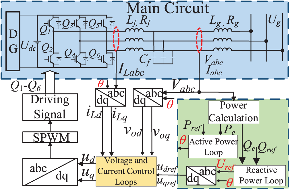
Figure 1: System structure of a GFM grid-connected converter
During the operation of a grid-forming converter, the DC power generated by distributed energy sources is converted into AC power through an inverter, with its core control based on the VSG strategy. The VSG controller first acquires the voltage and current at the PCC, and then calculates the active power Pe and reactive power Qe via a power computation module. Based on this, it generates a reference voltage Uref and phase angle θ.
Subsequently, a Park transformation is applied to convert the three-phase signals Uref, Vabc and Iabc from the stationary abc frame to the synchronous rotating dq0 frame, resulting in steady-state DC quantities. This facilitates simpler and more efficient control. The resulting dq components are fed into a dual-loop voltage and current control structure, enabling precise regulation of the inverter’s output.
Finally, an inverse Park transformation is used to reconstruct the three-phase sinusoidal reference signals. Sinusoidal Pulse Width Modulation (SPWM) is then employed to generate modulation waves and corresponding gate signals to control the switching states of power devices such as IGBTs. This process efficiently achieves DC-AC conversion, and the output is filtered through an LC filter before being delivered to the grid.
The VSG control loop mainly consists of two control layers. The first part is the outer power loop, where the active loop emulates the inertia and frequency modulation characteristics of SG, and the reactive loop stabilizes the output voltage by adjusting reactive power [24]. The corresponding control equations are given in Eq. (1) as follows.
where Pref and Pe, as well as Qref and Qe, respectively, represent the reference and actual values of active and reactive power. Dp and Dq respectively denote the damping factor and the reactive power-voltage droop coefficient. J represents the equivalent virtual moment of inertia, while K is the inertia control coefficient, ω and ωn represent the real-time angular frequency and its rated value, respectively, while V and Vn correspond to the current output voltage and the rated voltage, Em denotes the amplitude of the virtual armature electromotive force (EMF).
The second part is the inner voltage-current loop, which enables precise fault current regulation during FRT. As the LC filter forms a second-order system, the dual-loop control architecture enhances damping, suppresses resonance, and improves stability and response [25]. The voltage outer loop employs a PI controller to generate reference current signals, which are subsequently tracked by the current inner loop to regulate power flow. Eqs. (2) and (3) respectively represent the voltage and current loop control equations.
2.3 Positive and Negative Sequence Separation under Asymmetrical Faults
A three-phase three-wire system is used, where only positive and negative sequence components exist under asymmetrical faults. To achieve precise control, voltage and current signals must undergo positive-negative sequence decomposition, with negative sequence current regulated. As illustrated in Fig. 2, the DSOGI method for second-order filtering effectively extracts positive- and negative-sequence components., enhancing system stability and robustness against disturbances. Specifically, 3S/2S corresponds to the Clarke transformation, 2S/2R corresponds to the αβ–dq transformation, and Kso denotes the proportional gain. Eq. (4) defines the transfer function of the SOGI, where D(s) and Q(s) correspond to the band-pass and low-pass filter structures, respectively [26].
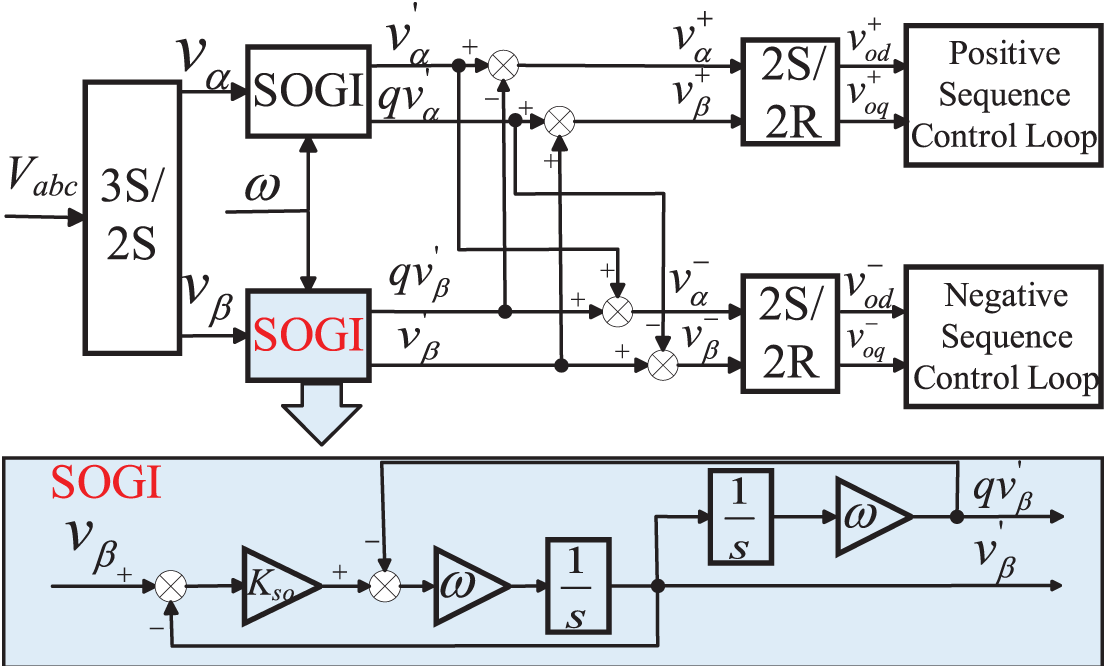
Figure 2: Overall control block diagram of DSOGI
3 Transient Response Characteristics of VSG to Grid Faults
3.1 Power Angle Characteristics
The power angle δ serves as a key indicator for evaluating the transient stability of VSGs. Post-fault system stability is determined by whether δ remains within a bounded range. Divergence of δ will lead to instability. δ represents the phase difference between inverter’s voltage E∠δ and grid voltage Ug∠0°, as mathematically defined Eq. (5).
The active and reactive power outputs of the converter are expressed by Eqs. (6) and (7), respectively.
Based on Eq. (6), the VSG power angle curve is plotted in Fig. 3, where curve I represents the pre-fault curve and curve II denotes the post-fault curve. The power angle variation during the fault is as follows:
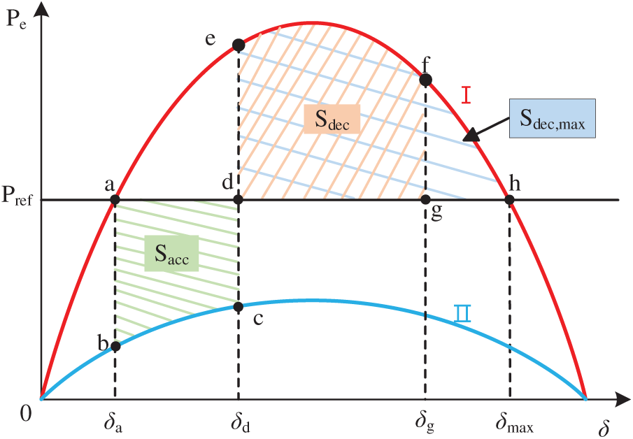
Figure 3: Power angle curve of the GFM converter
① Normal Operation Stage: The output power Pe = Pref, and the power angle is δa, corresponding to operating point a.
② Fault Occurrence Stage: The output power Pe decreases, the power-angle curve shifts from region I to region II, and the operating point moves from a to b.
③ Acceleration Stage: As Pref > Pe, under the action of the outer power control loop, dω/dt > 0, the power angle increases, and the operating point moves from b to c.
④ Fault Clearance Instant: The output power Pe increases, and the operating point shifts from c to e. The corresponding power angle δd is referred to as the critical angle, and the accumulated area is known as the acceleration area Sacc.
⑤ Deceleration Stage: As Pref < Pe, under the continued influence of the power control loop, dω/dt > 0, the power angle keeps increasing, and the operating point moves from e to f. The accumulated area during this stage is called the deceleration area Sdec.
⑥ Transient Stability Assessment: If the power angle δg at point f does not exceed the maximum angle δmax at point h, and the deceleration area Sdec does not exceed the maximum allowable deceleration area Sdec,max, the system is considered transiently stable. The operating point then returns from f to a, and stable operation is restored.
To ensure power angle stability, according to the equal-area criterion, the following condition must be satisfied: Sacc ≤ Sdec ≤ Sdec,max.
During grid faults that induce voltage sags, VSG’s active power decreases, and the limited bandwidth of the power loop results in delayed response, causing transient δ deviation and instability. Although the excitation system exhibits rapid dynamic response characteristics, it fails to provide instantaneous compensation during abrupt voltage drops. Concurrently, the increased reactive power demand can lead to insufficient reactive power injection. Therefore, coordinated active power regulation and reactive power compensation must be implemented simultaneously [27].
3.2 Fault Current Characteristics
During grid faults, the GFM inverter operates as a voltage source, and its constant potential during the initial fault stage causes a sudden voltage discrepancy with the grid, triggering a rapid current surge and active power imbalance. This results in δ expansion and fault overcurrent, threatening system stability. Consequently, coordinated control of δ and stringent fault current limitation are crucial. The equivalent circuit of the GFM inverter is shown in Fig. 4, where upcc(0−) and upcc(0+) respectively represent the grid voltage pre-fault and post-fault.
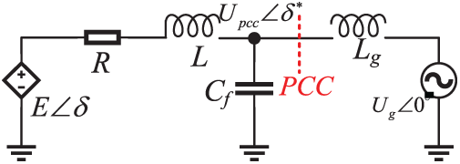
Figure 4: Power angle curve of the GFM converter
With reference to Fig. 4 and incorporating the resistive component of the system, the voltage current relationship can be derived based on Kirchhoff’s Voltage Law (KVL), as shown in Eq. (8).
The output current injected into the grid before the occurrence of the voltage sag is given as follows:
At the moment of the voltage sag, since the instantaneous voltage e of the converter remains unchanged, the instantaneous response of the fault current can be derived as follows:
During a fault, the fault current exhibits different characteristics at different stages, mainly consisting of a transient component iz and a steady-state component iw [16]. Therefore, the fault current if of the GFM inverter can be expressed as:
During grid voltage sags, upcc(0+) decreases. To suppress iz, the equivalent impedance can be adjusted to reduce the linear part and accelerate the decay of the nonlinear part. When iw increases, the steady-state component control is achieved by adjusting the equivalent impedance and power outer loop to control the internal potential.
4 Multi-Loop Coordinated Control Strategy for FRT
With the in-depth investigation of the FRT performance of GFM converters and the analysis of power angle and fault current characteristics, it is necessary to dynamically adjust the power reference in the outer power control loop during voltage sags caused by grid-side faults. Meanwhile, to suppress the increase in fault current, an adaptive virtual impedance is introduced into the inner control loop, enabling dynamic coordination between the inner and outer loops. As shown in Fig. 5, the proposed control strategy aims to mitigate the δ deviation and fault current surge under various fault conditions, thereby ensuring the safe and reliable operation of the GFM converter system.

Figure 5: Coordinated inner and outer loop control structure for FRT
4.1 Dynamic Regulation of the Outer Power Loop
During grid voltage sags, the limited bandwidth of the power control loop causes sluggish reactive current adjustment. Concurrently, the excitation system fails to provide instantaneous voltage compensation,
resulting in insufficient reactive power. To address this, a dynamic reactive power compensation strategy is implemented to provide voltage support [28], as shown in Eqs. (12) and (13).
where Qpu represents the per-unit value of reactive power, Upu denotes the per-unit value of the grid-side voltage amplitude, Spu represents the per-unit value of apparent power, and S represents the apparent power.
To ensure smooth FRT and system stability, a coordinated control strategy encompassing active power control, δ limitation, and fault current suppression are required in addition to reactive power compensation. As analyzed in Section 2.1, the dynamic behavior of δ is crucial for transient stability during voltage sags. Maintaining δ within a bounded stability margin improves system stability. By constraining the active power reference, the acceleration area Sacc is reduced. According to the equal area criterion and the fault ride-through process shown in Fig. 3, the deceleration area also decreases accordingly, thereby shifting the fault power angle δg to the left. This ensures that Sacc ≤ Sdec, minimizing the deviation of δ, as illustrated in Fig. 6.
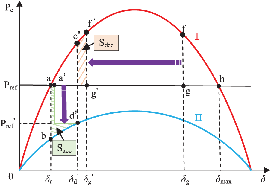
Figure 6: Improved active power loop’s power angle curve
The capacity of grid-connected converters is limited by their rated apparent power capacity. During grid faults, active power is regulated according to the relationship with apparent power, and the specific control method is shown in Eq. (14).
where Plim represents the maximum limit amplitude of the active power reference value, determined by the fault current multiplier Ilim. Due to the influence of power electronic devices within converters, it is essential to prevent thermal breakdown, overcurrent shutdown, and reduced device lifespan during FRT events. Therefore, the control strategy should be designed in accordance with the IEEE 1547–2018 standard [27] for electric power systems, which is designed as 1.2 p.u. The per-unit amplitudes of the converter’s active and reactive current components are denoted as Ipu,d and Ipu,q, as shown in Eqs. (15) and (16), respectively.
Thus, the maximum amplitude limit for obtaining the maximum active power reference value can be calculated using Eq. (17):
Through the dynamic regulation of active and reactive power, power angle deviation is minimized, the steady-state component of the fault current is reduced, and system stability is enhanced. At the same time, reactive power compensation is provided, offering strong voltage support on the grid side. However, the power control loop suffers from limitations such as narrow bandwidth and slow response, making it ineffective in controlling the transient components of the fault current during fault conditions. To address these transient issues, an analysis of the system’s dynamic behavior is conducted, and virtual impedance is employed to achieve effective control.
4.2 Dynamic Regulation of Positive-Sequence Voltage and Current Loops
The narrow bandwidth and sluggish response of the power loop significantly impair its capability to regulate the transient fault current components. As derived from Eq. (11), adjusting the equivalent impedance can suppress the current amplification. Since Rf and Lf are fixed, an adaptive virtual impedance Zv = Rv + jXv, as illustrated in Fig. 7, is introduced prior to the outer voltage and current loops to limit the voltage reference value, thereby reducing the current reference value and effectively limiting the fault current [29]. The virtual impedance Zv can be calculated by Eqs. (18) and (19).
where m denotes the virtual impedance coefficient, nX/R represents the virtual impedance ratio, Io is the root mean square (RMS) value of the fault current, while IL is the fault current threshold. To enhance the robustness of overcurrent limitation, IL is chosen to be slightly lower than Ilim, IL = 1.1 p.u.
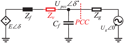
Figure 7: Equivalent circuit diagram with added Virtual Impedance
To accommodate various fault conditions, especially single-phase faults during voltage sags, the proposed control strategy dynamically adjusts the virtual impedance based on the maximum phase current. This aims to enhance the converter’s FRT capability by limiting the fault current while preserving voltage source characteristics.
To quantify the current magnitudes, the phase currents are decomposed into positive-sequence and negative-sequence components. The dq-frame magnitudes are given by:
Leveraging trigonometric functions, the current magnitudes in each phase (A, B, C) can be expressed as:
Here, the phase angle between the dq axes is denoted as φ(*), the composite phase angle difference α is defined as: α = φ(iP) – φ(iN) + φ(uP) – φ(uN). Therefore, the maximum effective value of the fault current can be expressed as:
This value serves as a critical metric for limiting the peak fault current through virtual impedance control. To mitigate the instantaneous voltage drop caused by sudden current injection during the fault, a dynamic virtual impedance is applied. It is designed to generate a compensating voltage ΔUm, defined as:
Based on Eqs. (23)–(25), the virtual impedance coefficient for the positive sequence component is derived as:
By dynamically adjusting the virtual impedance coefficient, the virtual impedance can adapt to the severity of the fault current, thereby achieving effective current suppression and enhancing fault ride-through capability.
4.3 Negative Sequence Current Loop Control
Under unbalanced faults, controlling only the positive-sequence current exacerbates voltage distortion. Precise control of the negative-sequence current is required to enhance system stability. Due to the limitation of steady-state current, conventional power reference adjustment strategies become ineffective. To achieve balanced three-phase current output, the negative-sequence current reference is enforced to zero [30]. A feedforward decoupling algorithm is implemented, governed by the following dynamic equation:
Recent advancements in GFM converters research have introduced stringent requirements for negative-sequence current control. During asymmetrical faults, it is imperative to inject negative-sequence reactive power must be compensated to reduce negative-sequence voltage and improve power quality. Thus, a dedicated negative-sequence current loop is implemented to regulate the output current. The resultant negative- sequence active and reactive power can be expressed as:
where
From Eqs. (28) and (29), it can be concluded that:
To inject negative-sequence reactive current into the inverter and offset the reverse voltage sags caused by the fault’s negative-sequence voltage,
The reference values of the inverter’s negative-sequence current are:
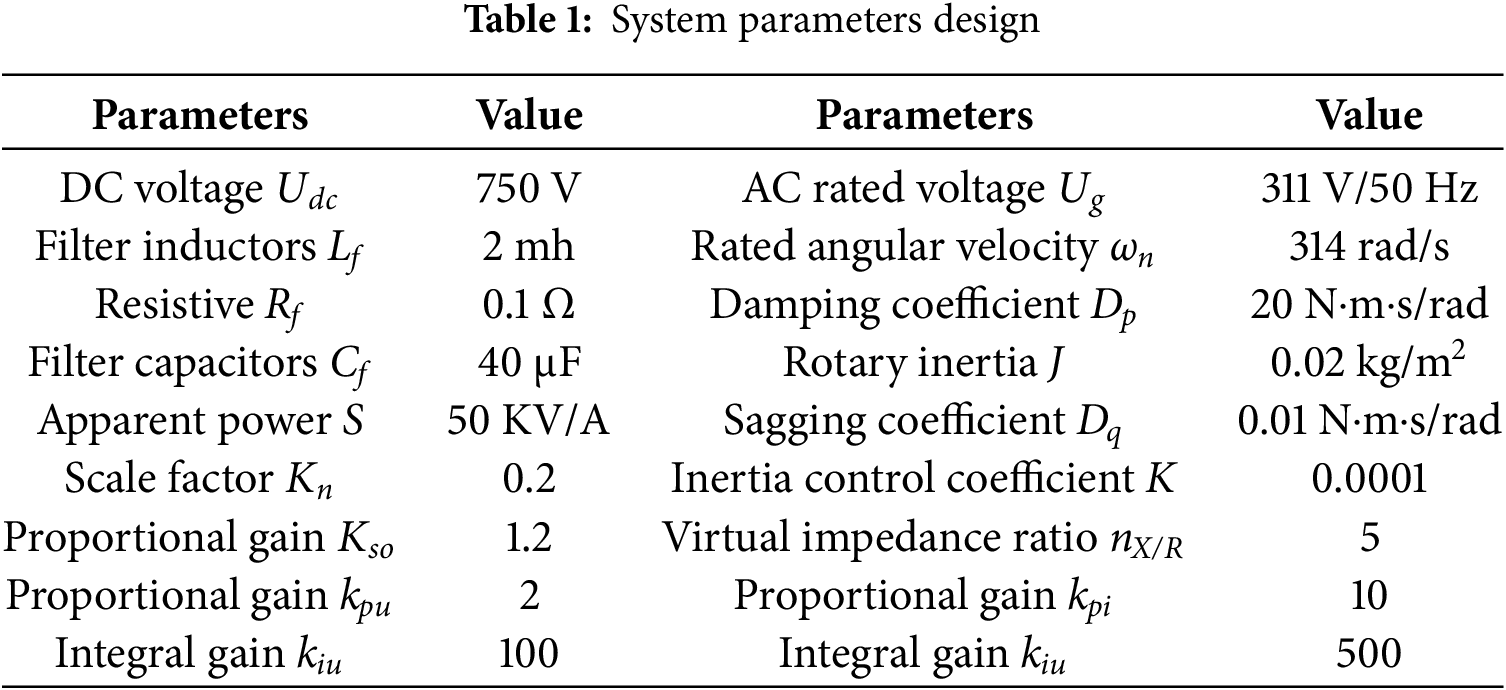
The proposed control strategy aims to limit power imbalance, reduce δ fluctuations, and restrict fault currents to ensure equipment safety. In the FRT simulation, the voltage sag is applied on the grid side at the PCC, corresponding to UPCC. The fault is initiated at t = 0.5 s and cleared at t = 1 s. To verify the effectiveness of the strategy, a converter model is built in MATLAB/Simulink, simulating symmetric and asymmetric faults. Some simulation parameters are shown in Table 1.
5.1 Simulation Analysis of Symmetrical Faults
In the symmetrical FRT simulation, the fault occurs at t = 0.5 s, where the three-phase voltage sags from 1 to 0.2 p.u., and recovers to 1 p.u. at t = 1 s. The power regulation with fixed virtual impedance, which lacks dynamic components, is taken as the baseline control strategy and compared with the improved coordinated inner- and outer-loop control strategy, as shown in Fig. 8. In the improved control simulation, the converter output is evaluated based on measurements at the PCC. The steady-state power angle of 0.126 radians during normal operation is selected as the base value and defined as 1 p.u. With this normalization, the active power output closely follows the reference, effectively mitigating power angle deviations during the fault period. A dynamic reactive power compensation loop is added to provide voltage support, while the adaptive virtual impedance suppresses the transient fault current, limiting it within 1.2 p.u., thereby ensuring system stability.

Figure 8: Performance comparison under symmetrical fault: improved vs. baseline control
5.2 Simulation Analysis of Asymmetrical Faults
In practical power grid operations, asymmetrical faults most commonly manifest as single-phase-to-ground faults and two-phase short-circuit faults. Therefore, to comprehensively evaluate the FRT capability of the proposed control strategy, this section conducts simulation analyses for both single-phase and two-phase fault scenarios, aiming to verify its adaptability and robustness under various types of asymmetrical faults. In the initial simulation analysis, a negative-sequence current suppression strategy is employed to ensure the inverter delivers balanced three-phase currents during fault conditions and to mitigate system impacts. Specifically, the control objective is set as i-dref = i-qref = 0, effectively suppressing the negative-sequence current to reduce system disturbances and prevent thermal damage to equipment. While this method demonstrates clear advantages in enhancing current output quality, it also presents certain limitations. Complete suppression of the negative-sequence current impairs the inverter’s ability to counteract negative-sequence voltage components from the grid, thereby restricting its capability to restore voltage symmetry. Consequently, Section 5.3 provides a separate analysis of a negative-sequence current compensation mechanism to address this issue.
Fig. 9 presents the simulation waveforms of active power, reactive power, power angle, output voltage, and output current under a single-phase-to-ground fault. The asymmetrical fault on the grid side is introduced at t = 0.5 s, where the voltage of phase A instantaneously drops from the rated value of 1.0 to 0.2 p.u., while the other two phases remain at the rated voltage. The fault is cleared at t = 1.0 s, and the grid voltage is restored to the rated level of 1.0 p.u. Fig. 10 shows the simulation results under a two-phase fault scenario. Similarly, the grid-side fault is applied at t = 0.5 s, during which the voltages of phases A and B drop from 1.0 to 0.2 p.u., while phase C remains unaffected. The fault is cleared at t = 1.0 s, and the system voltage returns to its nominal value of 1.0 p.u.
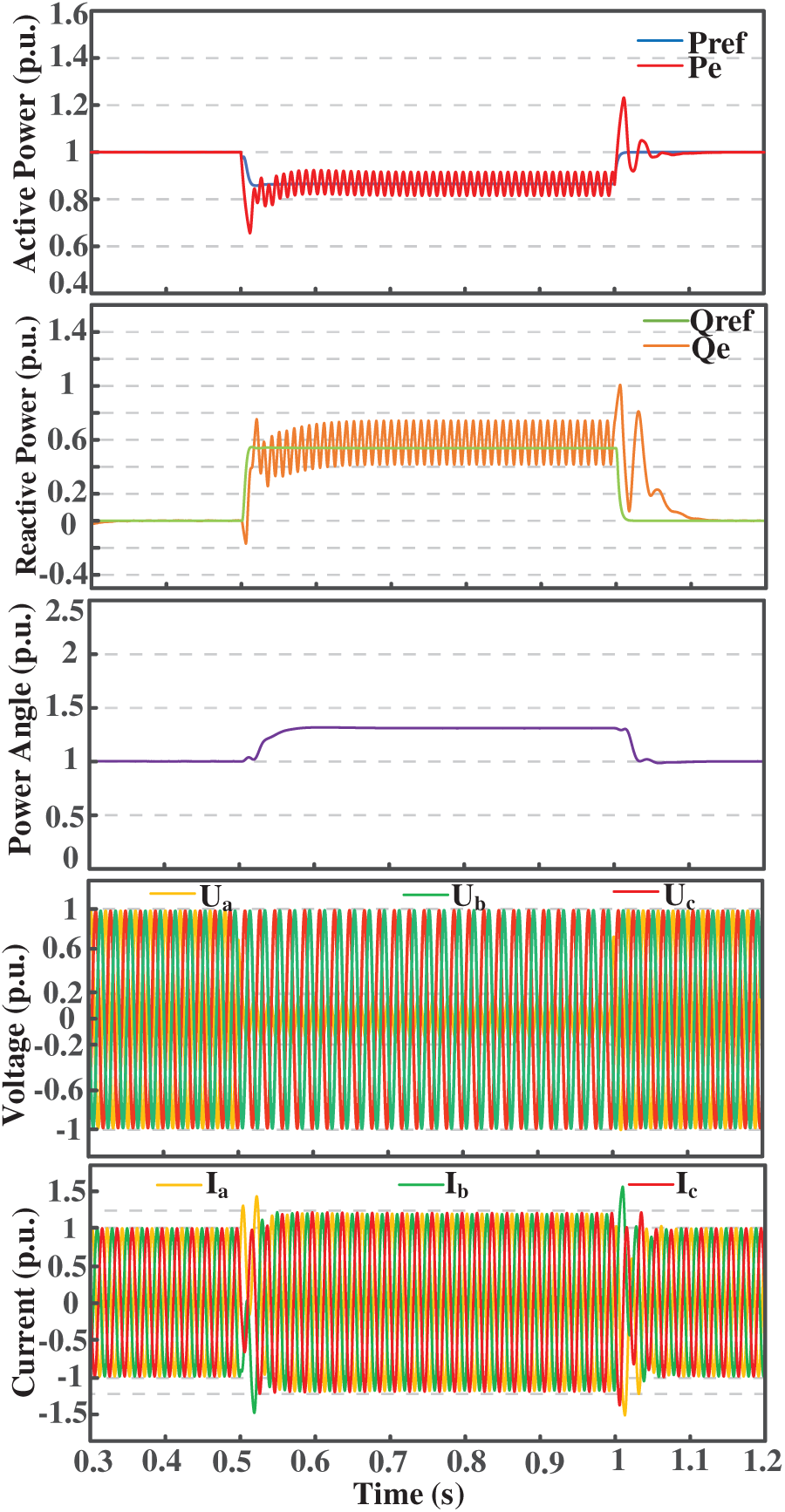
Figure 9: Waveform of single-phase ground fault
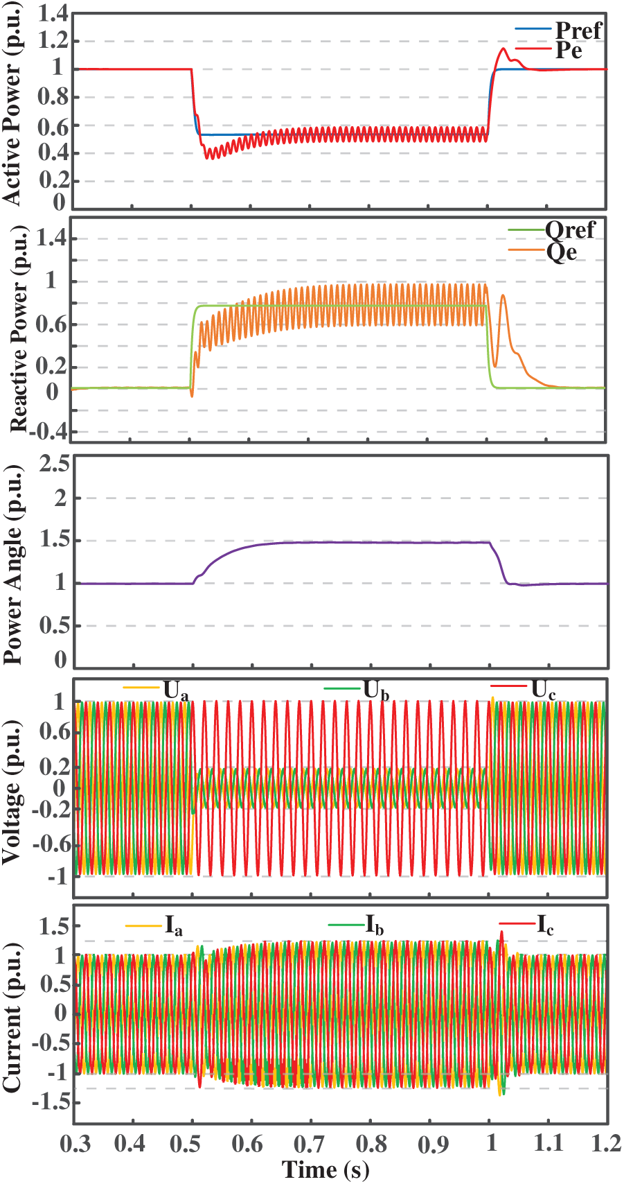
Figure 10: Waveform of two-phase short circuit fault
By utilizing a DSOGI, the fault voltages and currents are decomposed into positive- and negative-sequence components. While maintaining control over the positive-sequence components, the negative-sequence components are effectively suppressed. This approach mitigates double-frequency oscillations during the fault period, ensures that the active power Pe closely tracks the reference Pref, limits the power deviation, and reduces power angle fluctuations. Meanwhile, voltage support is provided during the fault through reactive power compensation, and the fault current is constrained within the predefined threshold of 1.2 p.u.
5.3 Simulation Analysis of Negative-Sequence Reactive Current Compensation
Although the negative-sequence current suppression strategy discussed in Section 5.2 demonstrates significant advantages in terms of current output quality, it also presents certain limitations. Specifically, the complete suppression of the negative-sequence current renders the system incapable of effectively counteracting the negative-sequence voltage components from the grid, thereby limiting its ability to restore voltage symmetry. To address this issue and effectively suppress the negative-sequence voltage generated during asymmetrical faults, a negative-sequence reactive current compensation mechanism described in Section 4.3 is introduced in the negative-sequence control loop. As shown in Fig. 11, when an asymmetrical fault occurs, the negative-sequence control loop outputs reactive current to compensate the grid, thereby mitigating the negative-sequence reactive voltage. Fig. 12 illustrates the waveform of the negative-sequence reactive voltage under both suppression and compensation strategies, highlighting the effectiveness of the compensation mechanism. It can be observed from the figure that, after introducing the negative-sequence reactive current compensation, a portion of the negative-sequence reactive voltage in the grid is offset. This results in a noticeable reduction of the negative-sequence reactive voltage, decreases voltage asymmetry on the grid side, and ultimately improves power quality.

Figure 11: Negative-sequence reactive current compensation

Figure 12: Negative-sequence voltage: suppression vs. compensation
To verify the performance of negative-sequence reactive current compensation under unbalanced fault conditions, a three-phase unbalanced fault scenario is configured. The fault occurs at t = 0.5 s, with A-phase voltage dropping to 0.2 p.u., B-phase to 0.4 p.u., and C-phase to 0.6 p.u., with fault clearance at t = 1 s and grid voltage recovering to 1 p.u. In Fig. 13, to ensure balanced three-phase current output and reduce system impact, a negative-sequence current suppression strategy was used, setting i-dref = i-qref = 0 to reduce disturbance and prevent thermal damage to the equipment. By controlling the positive-sequence components and suppressing the negative-sequence components, the double-frequency oscillations during the fault are reduced. Simultaneously, the active power Pe closely follows the reference Pref, limiting power deviations and minimizing δ fluctuations, with the fault current constrained within 1.2 p.u.
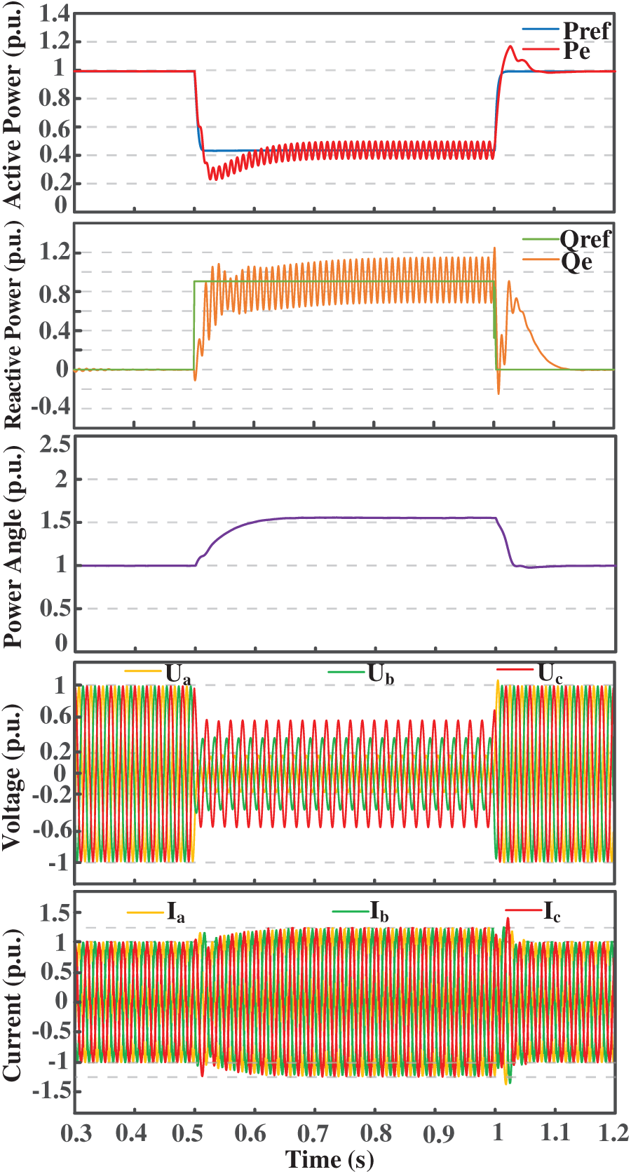
Figure 13: Simulation waveforms under negative-sequence reactive current suppression
Fig. 14 presents the simulation waveforms of asymmetrical fault conditions with negative-sequence reactive current compensation. Although the fault current slightly increases after introducing negative-sequence reactive current compensation compared to Fig. 13 without compensation, and an imbalance in the three-phase output currents appears, this is due to the injection of negative-sequence reactive current. This injection is equivalent to the inverter actively outputting a set of asymmetric current components superimposed on the original symmetrical positive-sequence current components. This is a deliberate trade-off by the inverter to compensate for grid imbalance and support the voltage.
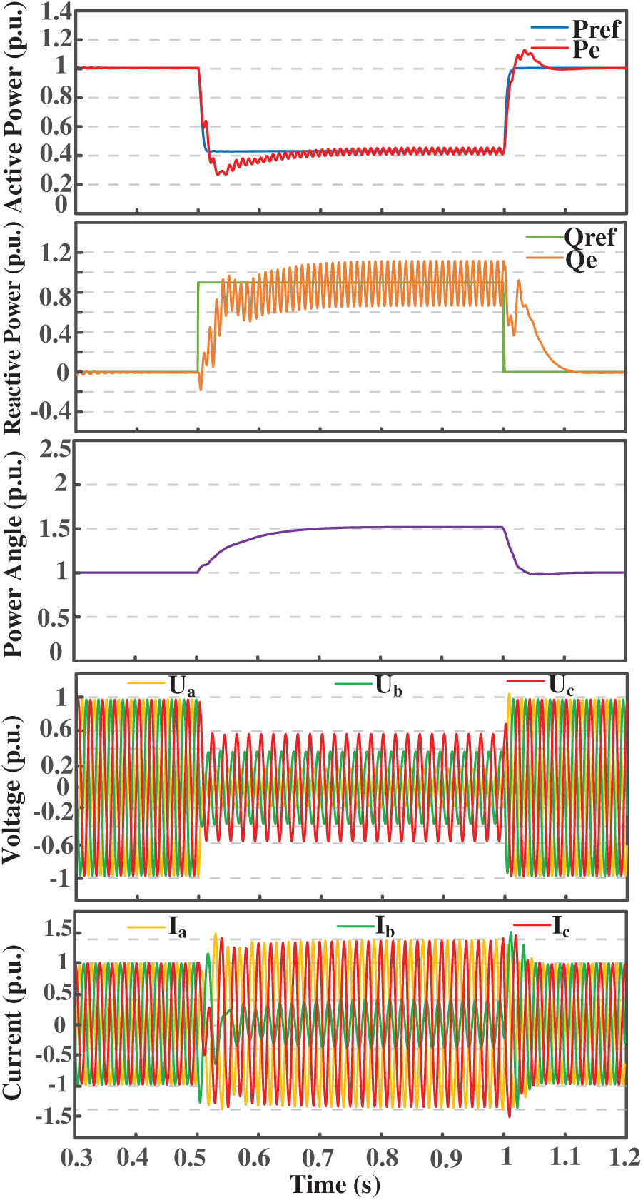
Figure 14: Simulation waveforms under negative-sequence reactive current compensation
In the context of fault ride-through for GFM converters, the proposed control strategy enables ride-through under various fault types, while maintaining voltage source characteristics, and providing effective voltage support. Key conclusions are as follows:
(1) An improved control strategy based on dynamic adjustment of the reference power is proposed for the outer power loop, effectively mitigating power angle deviation caused by active power imbalance. At the same time, adaptive reactive power compensation is performed according to the severity of the voltage sag, providing effective voltage support for the grid. This control strategy significantly enhances the system’s dynamic response and robustness.
(2) An adaptive virtual impedance is introduced to optimize the inner current control loop. By appropriately designing the virtual impedance parameters, effective limitation of fault currents under various fault types and severities is achieved. This enhances the system’s adaptability under fault conditions and ensures safe and stable operation.
(3) To address unbalanced faults, the introduced negative-sequence reactive current compensation effectively reduces the negative-sequence voltage components, significantly improving the voltage imbalance of the power grid. This enhances the voltage symmetry of the power system and improves overall power quality. Meanwhile, the proposed compensation strategy strengthens the system’s dynamic response and operational stability, providing a solid foundation for the secure and reliable operation of the grid.
Future work will focus on enhancing the engineering applicability and deployment scope of the proposed multi-loop coordinated control strategy. Hardware-in-the-loop (HIL) simulations and experiments will be conducted to verify its effectiveness and robustness under practical conditions. The strategy will also be extended to coordinated control of multiple GFM converters, high-penetration renewable systems, and AC/DC hybrid microgrids, with further investigation into its performance under communication delays and system disturbances.
Acknowledgement: Not applicable.
Funding Statement: The authors received no specific funding for this study.
Author Contributions: The authors confirm their contribution to the paper as follows: study conception and design: Zhuang Liu; data collection: Mingwei Ren; analysis and interpretation of results: Peifeng Xu, Kai Shi; draft manuscript preparation: Zhuang Liu. All authors reviewed the results and approved the final version of the manuscript.
Availability of Data and Materials: The authors confirm that the data used in this study are available on request.
Ethics Approval: Not applicable.
Conflicts of Interest: The authors declare no conflicts of interest to report regarding the present study.
Abbreviations
| GFM | Grid-Forming |
| FRT | Fault ride-through |
| GFL | Grid-Following |
| RES | Renewable energy sources |
| DSOGI | Dual second-order generalized integrator |
| VSG | Virtual synchronous generator |
| SGs | Synchronous generators |
References
1. Denis G, Prevost T, Debry M-S, Xavier F, Guillaud X, Menze A. The Migrate project: the challenges of operating a transmission grid with only inverter-based generation. A grid-forming control improvement with transient current-limiting control. IET Renew Power Gener. 2018;12(5):523–9. doi:10.1049/iet-rpg.2017.0369. [Google Scholar] [CrossRef]
2. Wu QH, Bose A, Singh C, Chow JH, Mu G, Sun Y, et al. Control and stability of large-scale power system with highly distributed renewable energy generation: viewpoints from six aspects. CSEE J Power Energy Syst. 2023 Jan;9(1):8–14. doi:10.17775/CSEEJPES.2022.08740. [Google Scholar] [CrossRef]
3. Rathnayake DB, Ghosh A, Mahmud MA, Vilathgamuwa DM. Grid forming inverter modeling, control, and applications. IEEE Access. 2021 Aug;9:114781–807. doi:10.1109/ACCESS.2021.3104617. [Google Scholar] [CrossRef]
4. Rosso R, Wang X, Liserre M, Lu X, Engelken S. Grid-forming converters: control approaches, grid-synchronization, and future trends—a review. IEEE Open J Ind Appl. 2021 Apr;2:93–109. doi:10.1109/OJIA.2021.3074028. [Google Scholar] [CrossRef]
5. Rahman K, Hashimoto J, Orihara D, Ustun TS, Otani K, Kikusato H, et al. Reviewing control paradigms and emerging trends of grid-forming inverters—a comparative study. Energies. 2024 May;17(10):2400. doi:10.3390/en17102400. [Google Scholar] [CrossRef]
6. Fan B, Liu T, Zhao F, Wu H, Wang X. A review of current-limiting control of grid-forming inverters under symmetrical disturbances. IEEE Open J Power Electron. 2022 Dec;3:955–69. doi:10.1109/OJPEL.2022.3227507. [Google Scholar] [CrossRef]
7. Zhou L, Liu S, Chen Y, Yi W, Wang S, Zhou X, et al. Harmonic current and inrush fault current coordinated suppression method for VSG under non-ideal grid condition. IEEE Trans Power Electron. 2020 Jan;36(1):1030–42. doi:10.1109/TPEL.2020.3000522. [Google Scholar] [CrossRef]
8. Shi K, Song W, Xu P, Ren M. Low-voltage ride-through control strategy for a virtual synchronous generator based on smooth switching. IEEE Access. 2018;6:2703–11. doi:10.1109/ACCESS.2017.2784846. [Google Scholar] [CrossRef]
9. Li Y, Gu Y, Green TC. Revisiting grid-forming and grid-following inverters: a duality theory. IEEE Trans Power Syst. 2022 Nov;37(6):4541–54. doi:10.1109/TPWRS.2022.3151851. [Google Scholar] [CrossRef]
10. Xiong X, Wu C, Blaabjerg F. Effects of virtual resistance on transient stability of virtual synchronous generators under grid voltage sag. IEEE Trans Ind Electron. 2021 Nov;69(5):4754–64. doi:10.1109/TIE.2021.3082055. [Google Scholar] [CrossRef]
11. Zhong Y, Chen C, Cui B, Bai C, He T. Low-voltage ride-through method for grid-forming converter based on adaptive virtual impedance. In: 2024 IEEE China International Youth Conference on Electrical Engineering (CIYCEE). Wuhan, China; 2024. p. 1–6. doi:10.1109/CIYCEE63099.2024.10846776. [Google Scholar] [CrossRef]
12. Zhou K, Yu L, Zhuo H, Duan S, Mo Z, Liu T. A new fault ride-through control strategy for virtual synchronous generator based on virtual impedance. In: 2023 10th International Forum on Electrical Engineering and Automation (IFEEA). Chongqing, China; 2023. p. 874–8. doi:10.1109/IFEEA60725.2023.10429426. [Google Scholar] [CrossRef]
13. Me SP, Zabihi S, Blaabjerg F, Bahrani B. Adaptive virtual resistance for post-fault oscillation damping with grid-forming control. IEEE Trans Power Electron. 2022 Apr;37(4):3813–24. doi:10.1109/TPEL.2021.3118677. [Google Scholar] [CrossRef]
14. Liu T, Wang X, Liu F, Xin K, Liu Y. A current limiting method for single-loop voltage-magnitude controlled grid-forming converters during symmetrical faults. IEEE Trans Power Electron. 2021 Apr;37(4):4751–63. doi:10.1109/TPEL.2021.3122744. [Google Scholar] [CrossRef]
15. Wang C, Zhang J, Yang H, Li Y. An improved grid-forming control strategy of energy storage system for enhancing low-voltage ride through capability. In: 2023 IEEE International Conference on Advanced Power System Automation and Protection (APAP). Nanjing, China; 2023. doi:10.1109/APAP59666.2023.10348485. [Google Scholar] [CrossRef]
16. Liu S, Hu P, Yu Y, Chen Z, Jiang D, Lin W. A novel fault ride through strategy for grid-connected virtual synchronous generators: power angle stability enhancement and current limiting. Int J Electr Power Energy Syst. 2024;162(2):110293. doi:10.1016/j.ijepes.2024.110293. [Google Scholar] [CrossRef]
17. Wang J, Zhang X. Active power and voltage cooperative control for improving fault ride-through capability of grid-forming converters. IEEE Trans Ind Electron. 2024 Oct;71(10):12301–11. doi:10.1109/TIE.2023.3340202. [Google Scholar] [CrossRef]
18. Ji F, Xu Z. Enhancement of low-voltage ride-through capability for virtual synchronous generators based on virtual impedance voltage control. Energy Rep. 2023;9(8):406–15. doi:10.1016/j.egyr.2023.10.045. [Google Scholar] [CrossRef]
19. Luo R, Zhang L, Wang Y, Li Y. An adaptive low-voltage ride-through method for virtual synchronous generators during asymmetrical grid faults. IEEE Trans Sustain Energy. 2024 Jul;15(3):1589–1600. doi:10.1109/TSTE.2024.3358394. [Google Scholar] [CrossRef]
20. Li Z, Wang H, Chen Y, Zhang X. An adaptive fault ride-through scheme for grid-forming inverters under asymmetrical grid faults. IEEE Trans Ind Electron. 2021 Dec;69(12):12912–23. doi:10.1109/TIE.2021.3135641. [Google Scholar] [CrossRef]
21. Khan I, Doolla S. Improved fault ride-through response of grid forming inverters under symmetrical and asymmetrical faults. IEEE Trans Energy Convers. 2024 Mar;39(1):45–56. doi:10.1109/TEC.2024.3419010. [Google Scholar] [CrossRef]
22. Rosso R, Engelken S, Liserre M. On the implementation of an FRT strategy for grid-forming converters under symmetrical and asymmetrical grid faults. IEEE Trans Ind Appl. 2021 Sep/Oct;57(5):4385–97. doi:10.1109/TIA.2021.3095025. [Google Scholar] [CrossRef]
23. IEEE Standards Association. IEEE standard for interconnection and interoperability of inverter-based resources (IBRs) interconnecting with associated transmission electric power systems. IEEE Std 2800-2022. 2022 Apr 22:1–180. doi:10.1109/IEEESTD.2022.9762253. [Google Scholar] [CrossRef]
24. Cheema KM. A comprehensive review of virtual synchronous generator. Int J Electr Pow Energy Syst. 2020;120:106006. doi:10.1016/j.ijepes.2020.106006. [Google Scholar] [CrossRef]
25. Geng Y, Yun Y, Chen R, Wang K, Bai H, Wu X. Parameters design and optimization for LC-type off-grid inverters with inductor-current feedback active damping. IEEE Trans Power Electron. 2018 Jan;33(1):703–15. doi:10.1109/TPEL.2017.2664812. [Google Scholar] [CrossRef]
26. Rodriguez P, Luna A, Muñoz-Aguilar RS, Candela I, Teodorescu A, Blaabjerg F. A stationary reference frame grid synchronization system for three-phase grid-connected power converters under adverse grid conditions. IEEE Trans Power Electron. 2012 Jan;27(1):99–112. doi:10.1109/TPEL.2011.2151206. [Google Scholar] [CrossRef]
27. IEEE Standards Association. IEEE standard for interconnection and interoperability of distributed energy resources with associated electric power systems interfaces. IEEE Std 1547-2018 (Revision of IEEE Std 1547-2003). 2018 Apr 6:1–138. doi:10.1109/IEEESTD.2018.8332112. [Google Scholar] [CrossRef]
28. Liu Y, Meng J, Wang Y, Wang J, Liang R, Zhang Z. Adaptive virtual impedance current limiting strategy for grid-forming converter. In: 2023 8th Asia Conference on Power and Electrical Engineering (ACPEE). Tianjin, China; 2023. p. 653–7. doi:10.1109/ACPEE56931.2023.10135946. [Google Scholar] [CrossRef]
29. Paquette AD, Divan DM. Virtual impedance current limiting for inverters in microgrids with synchronous generators. IEEE Trans Ind Appl. 2015 Mar/Apr;51(2):1630–8. doi:10.1109/TIA.2014.2345877. [Google Scholar] [CrossRef]
30. Mahamedi B, Eskandari M, Fletcher JE, Zhu J. Sequence-based control strategy with current limiting for the fault ride-through of inverter-interfaced distributed generators. IEEE Trans Sustain Energy. 2020 Jan;11(1):165–74. doi:10.1109/TSTE.2018.2887149. [Google Scholar] [CrossRef]
Cite This Article
 Copyright © 2026 The Author(s). Published by Tech Science Press.
This work is licensed under a Creative Commons Attribution 4.0 International License , which permits unrestricted use, distribution, and reproduction in any medium, provided the original work is properly cited.
 Downloads
 Citation Tools