
 Submit a Paper
 Propose a Special lssue
 Open Access
ARTICLE
Construction of MMC-CLCC Hybrid DC Transmission System and Its Power Flow Reversal Control Strategy
1 Key Laboratory of Modern Power System Simulation and Control & Renewable Energy Technology, Northeast Electric Power University, Jilin, 132012, China
2 State Grid Henan Economic and Technical Research Institute, Zhengzhou, 450000, China
* Corresponding Author: Tuo Wang. Email:
Energy Engineering 2026, 123(1), 21 https://doi.org/10.32604/ee.2025.069748
Received 30 June 2025; Accepted 26 August 2025; Issue published 27 December 2025
 View Full Text
 Download PDF
Abstract
To enhance power flow regulation in scenarios involving large-scale renewable energy transmission via high-voltage direct current (HVDC) links and multi-infeed DC systems in load-center regions, this paper proposes a hybrid modular multilevel converter–capacitor-commutated line-commutated converter (MMC-CLCC) HVDC transmission system and its corresponding control strategy. First, the system topology is constructed, and a submodule configuration method for the MMC—combining full-bridge submodules (FBSMs) and half-bridge submodules (HBSMs)—is proposed to enable direct power flow reversal. Second, a hierarchical control strategy is introduced, including MMC voltage control, CLCC current control, and a coordination mechanism, along with the derivation of the hybrid system’s power flow reversal characteristics. Third, leveraging the CLCC’s fast current regulation and the MMC’s negative voltage control capability, a coordinated power flow reversal control strategy is developed. Finally, an 800 kV MMC-CLCC hybrid HVDC system is modeled in PSCAD/EMTDC to validate the power flow reversal performance under a high proportion of full-bridge submodule configuration. Results demonstrate that the proposed control strategy enables rapid (1-s transition) and smooth switching of bidirectional power flow without modifying the structure of primary equipment: the transient fluctuation of DC voltage from the rated value (UdcN) to the maximum reverse voltage (-kUdcN) is less than 5%; the DC current strictly follows the preset characteristic curve with a deviation of ≤3%; the active power reverses continuously, and the system maintains stable operation throughout the reversal process.Keywords
Under the Paris Agreement’s 1.5°C pathway, global carbon neutrality commitments have accelerated, with China—contributing ~30% of worldwide CO2 emissions—announcing its Dual Carbon Goals as a national strategy [1,2]. Driven by the strategic objectives of “carbon peak and carbon neutrality” [3], the development of large-scale renewable energy bases in western China has become a critical national energy priority. The geographical mismatch between these renewable energy bases and major load centers necessitates bulk power transmission via High-voltage direct current (HVDC) links to receiving-end grids, forming multi-infeed HVDC systems [4]. However, the intermittent and volatile nature of renewable generation creates operational challenges: during periods of low renewable output, power deficits may occur, requiring the receiving-end grid to reverse power flow through HVDC channels to maintain system stability. Moreover, the dense concentration of multiple DC infeeds in receiving-end grids increases operational vulnerability, especially under fault disturbances, due to insufficient AC system strength, which elevates the risk of commutation failure. Consequently, the bidirectional power flow requirement presents substantial challenges to the power reversal capabilities of conventional HVDC transmission systems.
There are multiple pathways to construct the transmission methods for large-scale renewable energy to receiving-end grids [5]. Among established solutions, line-commutated converter (LCC)-HVDC technology known for its technical maturity and cost-effectiveness, holds a significant advantage in long-distance, high-capacity transmission scenarios [6,7]. However, as a semi-controlled device, thyristors rely on the commutation voltage provided by the connected AC grid for their commutation process, which fails to offer effective voltage support for stable renewable energy operation. Furthermore, AC system faults at the receiving end can trigger commutation failures or even converter blockings [8], causing severe power fluctuations or complete transmission interruptions that jeopardize grid stability across both sending and receiving systems [9]. In contrast, modular multilevel converter (MMC)-based HVDC technology, with its independent active and reactive power control capabilities [10,11] and its ability to supply voltage support for renewable energy [12] highlights notable technical benefits in renewable integrating ources scenarios [13]. Nevertheless, the reliance on numerous fully controllable insulated gate bipolar transistor (IGBT) devices leads to substantially higher costs and increased power losses compared to LCC-HVDC, undermining its economic viability. Reference [14] innovatively proposed a controllable line-commutated converter (CLCC) topology, which innovatively combines fully controllable IGBTs with semi-controlled thyristors. This hybrid design retains the benefits of LCC technology—high transmission capacity, lower cost, and reduced losses [15]—while acquiring controllable turn-off capability that effectively mitigates commutation failure risk.
To leverage the strengths of different technologies and tailor to the characteristics of the connected AC systems, constructing hybrid HVDC transmission systems has become a solution for HVDC projects. Operational examples include: The ±800 kV Kunliulong project (commissioned 2020), featuring a sending-end LCC and a receiving-end hybrid MMC (combining full-bridge and half-bridge submodules, FHMMC) [16]. The Baihetan-Jiangsu project (2020), utilizing an LCC-MMC cascade structure for flexible power distribution and optimized control [17]. The Gezhouba-Nanqiao DC renovation project (2023), adopting an LCC-CLCC topology to suppress commutation failure risk in the multi-infeed high-voltage direct current (MI-HVDC) system and enhance overall grid reliability [18]. These developments underscore the need for optimized HVDC system configurations tailored to scenarios involving large-scale renewable energy export and multi-infeed DC systems in load centers.
However, existing hybrid HVDC schemes currently encounter major challenges in handling the frequent bidirectional power flow driven by the volatility of large-scale new energy: Inverter stations adopting LCC or conventional LCC-MMC hybrid configurations remain prone to commutation failure in weak AC systems, which makes it difficult to meet the strict requirements for high reliability of multi-infeed DC receiving-end power grids. Although the pure MMC scheme can avoid commutation failure and provide flexible control, its high construction and operation costs limit its wide application in ultra-large capacity transmission projects. Traditional DC power flow reversal methods usually require system blocking and voltage polarity switching [19], resulting in power interruption, which cannot meet the demand for millisecond-level smooth power flow switching required by the rapid changes in new energy output or adjustments in system operation modes. Although there are online reversal schemes without blocking [20], their practicality (such as the complexity of engineering implementation) or reliability (such as the problem of insulation recovery) still need to be improved.
Therefore, this study seeks to tackle the main challenges in large-scale renewable energy transmission and the stability of multi-infeed DC load centers, with core objectives as follows:
(1) To develop a hybrid HVDC topology that balances new energy integration flexibility and system reliability/economy—resolving the limitations of standalone MMC (high cost) or LCC (commutation failure risk) systems in complex scenarios.
(2) To achieve online, fast, and smooth power flow reversal—eliminating the need for converter blocking, DC line polarity conversion, or primary equipment modification, thus adapting to renewable energy volatility and improving grid operational flexibility.
To achieve the above objectives, this paper proposes a novel MMC-CLCC hybrid HVDC transmission system, with three key contributions:
(1) Novel System Topology & Submodule Configuration: We design a hybrid topology where the sending-end adopts MMC (for renewable energy voltage support) and the receiving-end uses CLCC (for commutation failure immunity and cost-effectiveness). A dedicated FB-HB submodule configuration method for MMC is further proposed to enable direct power flow reversal without hardware upgrades.
(2) Hierarchical Coordinated Control Framework: We establish a multi-layer control strategy integrating MMC voltage control (to stabilize DC voltage), CLCC current control (to track power direction), and an inter-converter coordination mechanism. This framework derives the hybrid system’s power flow reversal characteristic curve, laying the theoretical foundation for smooth reversal.
(3) Optimized Reversal Control Strategy: Leveraging CLCC’s fast current regulation capability and MMC’s negative voltage output potential, we develop a dedicated reversal control strategy. This strategy achieves online power flow switching (e.g., from 1600 to −1600 MW within 1 s) with DC voltage/current fluctuations limited to ±5% of rated values, fully meeting practical engineering requirements for renewable energy integration and multi-infeed DC stability.
2 MMC-CLCC Hybrid DC System Configuration
This paper presents an 800 kV/1600 MW MMC-CLCC hybrid HVDC transmission system, illustrated in Fig. 1, designed for large-scale renewable energy transfer and multi-infeed DC systems in load-center regions. The sending-end AC system combines large-scale renewable energy bases, small conventional generation units, and local loads. The receiving-end AC system is a typical load center area with several DC feeds. Bidirectional power flow may be required during system operation mode adjustments, renewable power fluctuations, or load variations.
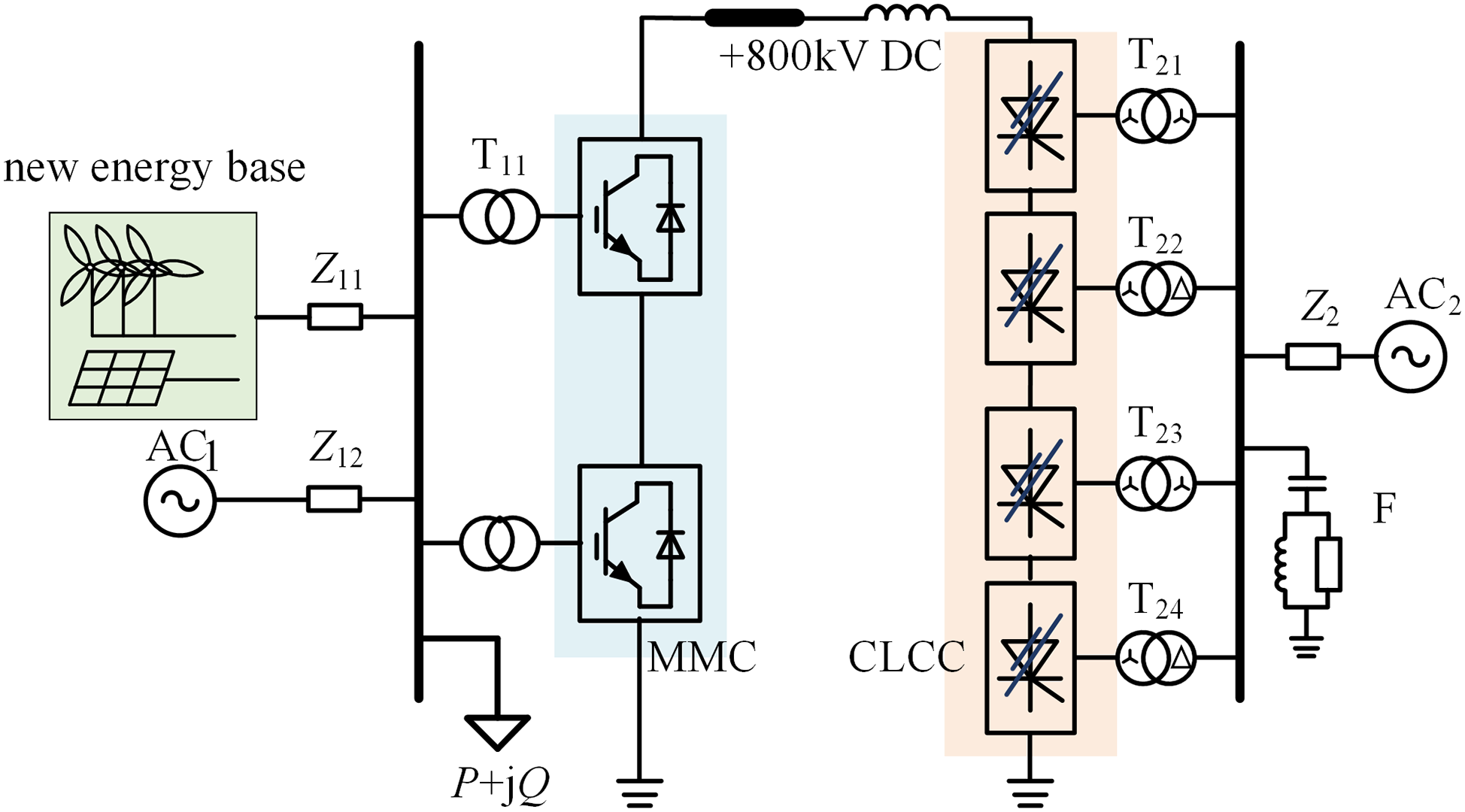
Figure 1: MMC-CLCC hybrid DC transmission system
The rectifier station uses FHMMC, while the inverter side features dual 12-pulse CLCC. AC1 and AC2 are equivalent AC sources at the sending and receiving ends, respectively. Z11, Z12, and Z2 represent the system’s equivalent impedance, and F denotes AC filters and reactive power compensation devices.
2.1 FHMMC Topology and FB/HB Submodule Ratio Selection
In MMC topologies, half-bridge submodules (HBSMs) offer structural simplicity and low cost but cannot generate negative voltage levels, requiring converter blocking and operational mode switching for power flow reversal. Full-bridge submodules (FBSMs) enable rapid DC voltage polarity reversal but suffer from doubled device counts, increased costs, and higher losses. FHMMC combines the economic benefits of HBSMs with the polarity reversal capability of FBSMs, achieving millisecond-level polarity reversal without converter blocking or mode switching—ideal for frequent bidirectional power flow caused by renewable fluctuations.
Fig. 2 illustrates the basic topology of FHMMC, featuring a three-phase six-bridge arm configuration. Each arm is made up of N submodules connected in series, which include NF FBSMs and NH HBSMs. The arm inductor L0 helps to reduce circulating currents and control the rate at which fault currents increase.
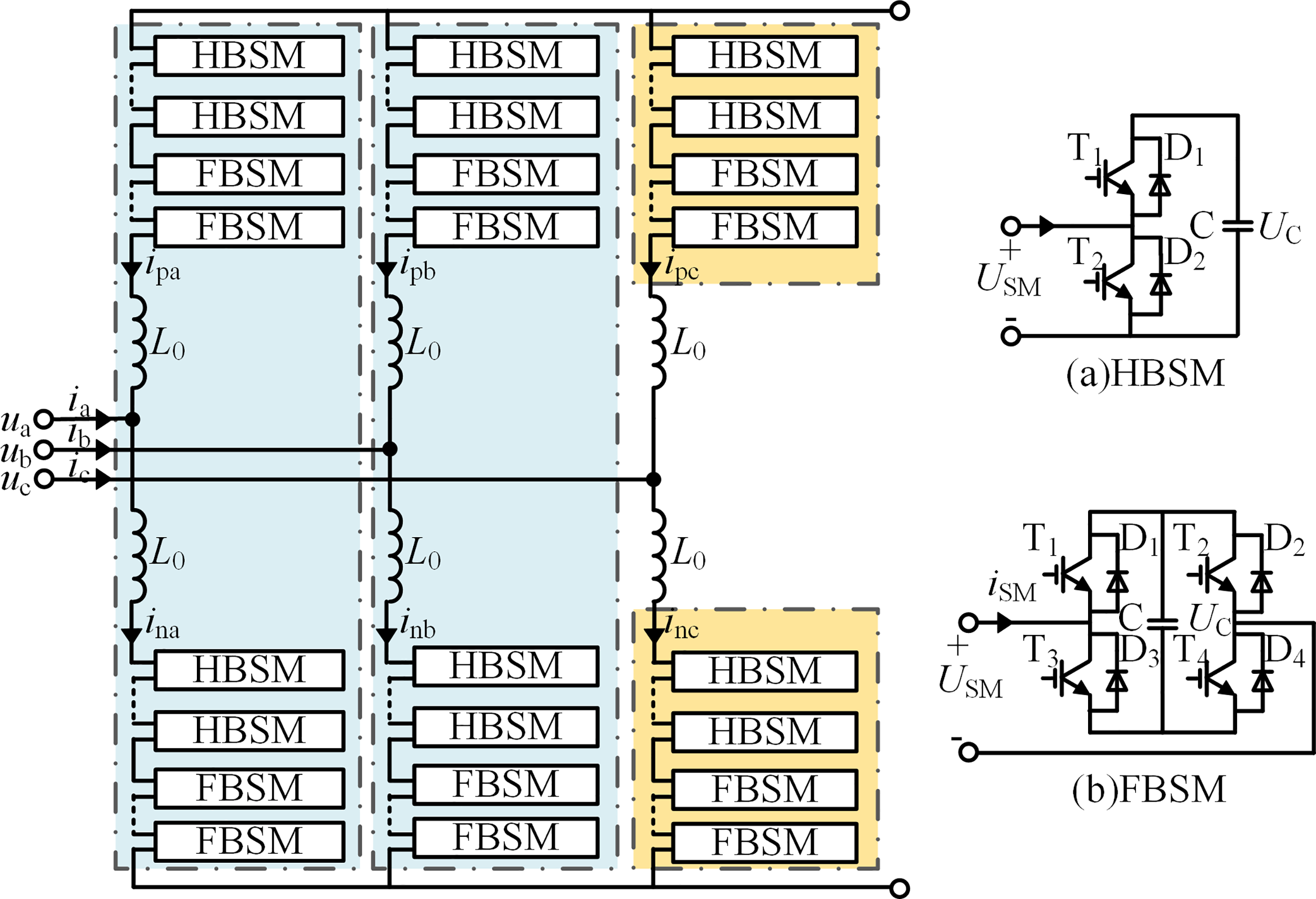
Figure 2: Basic topology of FHMMC converter
2.1.2 FB/HB Submodule Ratio Selection Methodology
Through its unique hybrid submodule architecture, the FHMMC integrates DC fault clearance and power flow reversal capabilities when the ratio of full-bridge to half-bridge submodules meets specific requirements.
For the FHMMC, the DC modulation ratio mdc and AC modulation ratio mac are defined as shown in Eq. (1):
where: Udc is the actual operating DC voltage; UdcN is the rated DC voltage; Usm is the peak AC voltage; * represents the per-unit value. The voltages at the output of the upper and lower arms in the MMC are provided by:
where: upj and unj represent the output voltages of the upper and lower arms, respectively, in phase j; usj indicates the AC-side output voltage of phase j. The specific expressions are provided by:
By combining Eqs. (1) and (2), the voltage range for phase-j converter arms is derived as:
(1) FBSM Ratio for DC Fault Clearance
To ensure DC fault ride-through without blocking and to maintain STATCOM operation capability during grid disturbances, the number of full-bridge submodules, NF, must meet the condition specified in Eq. (5):
Combining Eqs. (1) and (5), the minimum FBSM ratio k for effective DC fault ride-through is derived in Eq. (6):
The typical operating range for the AC modulation ratio (mac) is from 0.9 to 1.0, which helps maintain system stability and high-quality output voltage. When mac = 1, the minimum FBSM ratio required for DC fault clearance is 50%.
(2) FBSM Ratio Configuration Principle for Power Flow Reversal
To support the need for power flow to reverse direction, the operational sequence involves: reducing DC voltage and current, reversing converter voltage polarity, and utilizing FHMMC’s negative voltage capability to rebuild reverse-polarity power flow. The maximum forward and reverse DC voltages achievable by the FHMMC are expressed in Eq. (7):
This defines the DC voltage operating boundaries:
where: maximum positive voltage: +UdcN (all submodules contribute); maximum negative voltage: −kUdcN (limited by FBSMs).
To ensure stable power flow reversal, the proportion of FBSMs k must exceed 50%, which satisfies two fundamental requirements: sufficient reverse voltage capability (|Udcmin| > 0.5UdcN) for rated power transmission without exceeding DC current constraints, and compliance with the fault ride-through criterion (k > mac/2) defined in Eq. (6) to maintain STATCOM capability during grid disturbances.
Synthesizing the above analysis, an FBSM ratio between 50% and 100% enables FHMMC to achieve both DC fault ride-through and millisecond-level power flow reversal. This configuration maintains appropriate fault tolerance while providing adequate negative voltage output capacity, making it particularly suitable for scenarios with high renewable energy penetration that require frequent bidirectional power flow.
The CLCC topology consists of six converter valves, as shown in Fig. 3a, where Ud represents the DC output voltage and Id denotes the DC current. Fig. 3b depicts the electrical layout of a single valve, which includes the main branch (V11, V12) and the auxiliary branch (V13, V14).
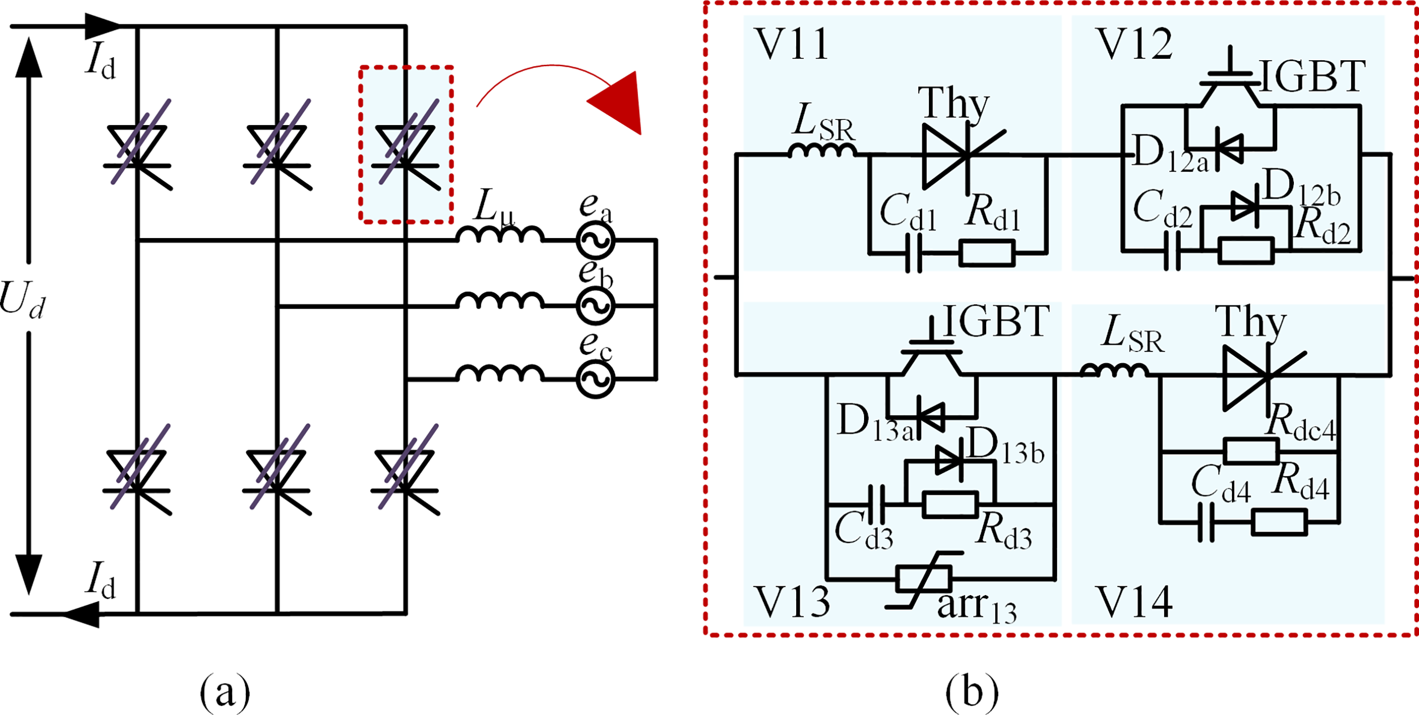
Figure 3: CLCC valve topology: (a) converter assembly; (b) single valve structure
The controllable commutation mode of the CLCC consists of two states: natural commutation and forced commutation. Fig. 4 illustrates its operational path and the switching sequence of each device in the converter valve.
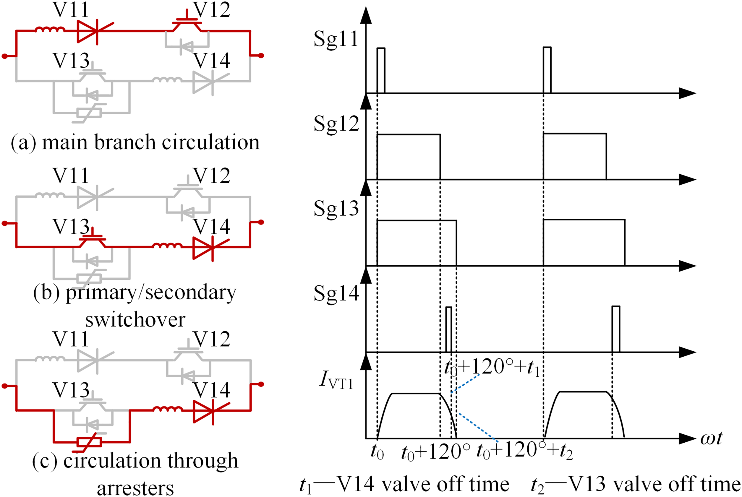
Figure 4: CLCC operating sequence of path and valve switching
During natural commutation, the auxiliary branch current naturally decreases to zero when the AC system voltage is present. In forced commutation, fault current is redirected through arrester arr13, which supplies extra commutation voltage to facilitate successful switching. This dual-mode design maintains the economic advantages of traditional LCC technology while significantly enhancing commutation reliability during AC system faults.
2.3 Overall System Composition and Parameter Specification
This paper proposes an 800 kV MMC-CLCC hybrid HVDC transmission system with a capacity of 1600 MW, designed to handle large-scale renewable energy transmission and multi-infeed DC systems in load centers (see Fig. 1). The system consists of a sending-end FHMMC converter station, a receiving-end CLCC converter station, an overhead DC line, and auxiliary equipment. The design principles for each component are outlined below.
2.3.1 Sending-End FHMMC and AC-Side Configuration
The sending-end FHMMC converter station connects to a 380 kV AC system that integrates large-scale wind, solar, and energy storage facilities, utilizing a three-phase six-arm topology. According to the analysis in Section 2.1.2, the submodule configuration uses a hybrid of FBSMs and HBSMs, where the proportion of FBSMs (k) ≥50% (meeting the DC fault ride-through requirement in Eq. (6) and the negative voltage output capability in Eq. (8)). The arm inductor is designed to be 29 mH to suppress circulating currents and limit the rate of fault current rise, and the converter transformer adopts a 380/220 kV turns ratio to achieve voltage matching.2.3.2 Receiving-End CLCC and AC-Side Configuration.
The receiving-end CLCC converter station adopts a dual 12-pulse topology connected to the 525 kV load center grid, with its innovative valve structure integrating thyristor-based main branches (V11, V12) and IGBT-based auxiliary branches (V13, V14). Through the collaboration of natural commutation and forced commutation modes, it significantly enhances immunity to commutation failures in multi-infeed systems. The converter transformer is designed with a 500/175 kV turns ratio, and is equipped with static var compensators (SVC) and shunt capacitor banks to maintain voltage stability at the receiving end. The control system adopts a constant DC current strategy, coordinating with the sending-end FHMMC through dynamic adjustment of the firing angle.
2.3.2 DC Line and Key Equipment
The DC line and key equipment are constructed based on the CIGRE standard test system, with line parameters optimized for long-distance transmission requirements. The DC side is configured with 0.9 H/pole smoothing reactors to suppress ripples and limit fault currents, 28 μF/pole filters to eliminate 12th/24th harmonic components, and a 5 Ω grounding resistance system to ensure that the grounding current does not exceed 60 A.
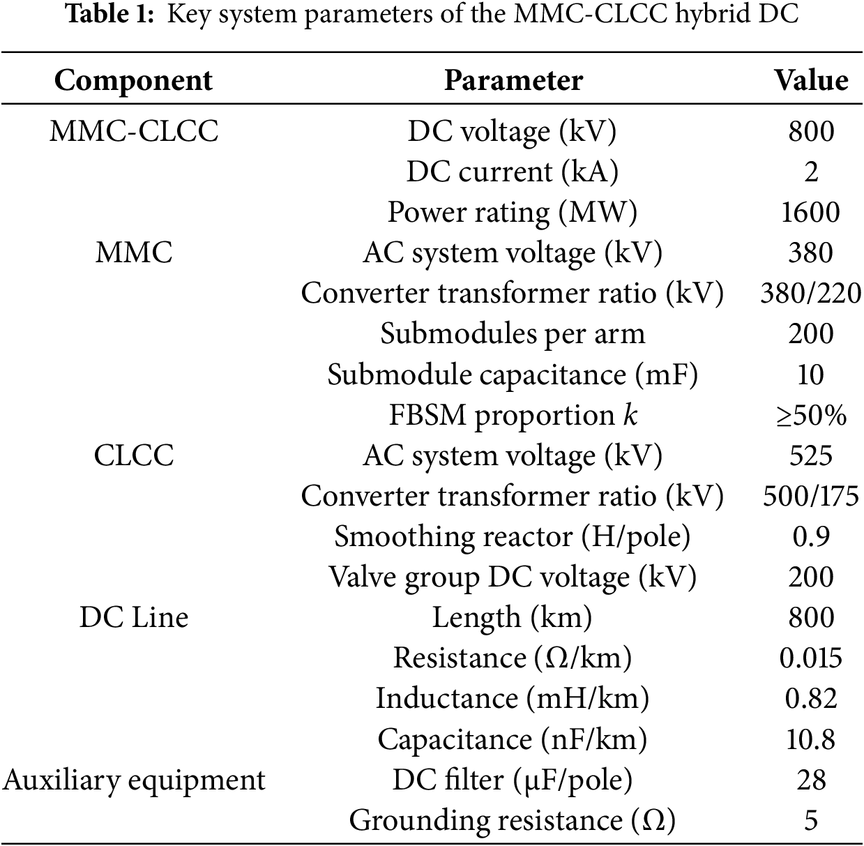
2.3.3 Simulation Modeling and Core Parameters
The simulation modeling is based on the PSCAD/EMTDC platform. The FHMMC adopts a switching model with nearest level modulation (NLM) (submodule capacitance of 10 mF), and the CLCC model accounts for thyristor turn-off time and commutation capacitor dynamics. The core parameters of the system, verified through theoretical derivation and engineering practice, are summarized in Table 1 as a unified benchmark.
3 Control Strategy and Power Flow Reversal Characteristics
The following control strategies are implemented to ensure the stable operation of the MMC-CLCC hybrid HVDC transmission system.
The MMC employs a straightforward DC vector control method. In this approach, capacitor voltage or DC voltage are used to manage active power, while AC voltage takes care of reactive power, as shown in Fig. 5.
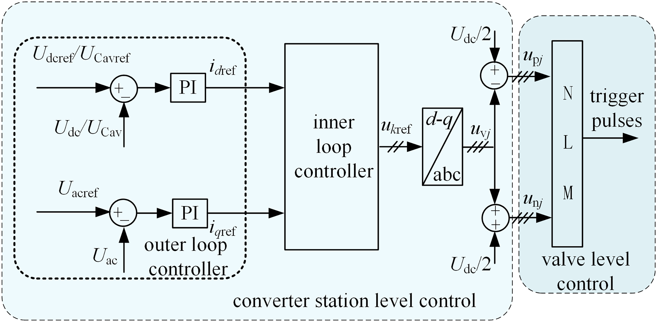
Figure 5: MMC converter control block diagram
The CLCC utilizes constant DC current control. This method takes the absolute value of the measured DC voltage before inputting it into the predefined power flow reversal control curve. This ensures that during voltage zero-crossings, the reference current Idcref remains independent of voltage polarity. The CLCC adjusts the firing angle α based on Idcref, maintaining a consistent control architecture while autonomously adapting α to polarity changes. This control curve enables seamless polarity reversal under both positive and negative voltage conditions while maintaining power continuity through dynamic current tracking. It effectively enhances transient stability, prevents DC overvoltage and power interruption during zero-crossing through enforced minimum current limits, and accommodates various fault ride-through scenarios. The control block diagram is shown in Fig. 6.
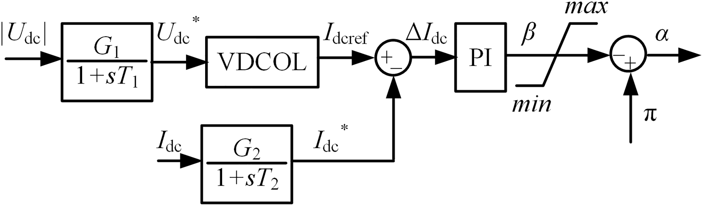
Figure 6: CLCC converter control block diagram
The characteristic curve illustrating the power flow reversal for the MMC-CLCC hybrid system is depicted in Fig. 7, where Idcmin represents the minimum current limit ensuring smooth power transition and preventing commutation valve overvoltage due to current discontinuity. Points A, B, and C correspond to the steady-state operating point, reversal initiation point, and minimum current maintenance point, respectively.

Figure 7: Characteristic curve of power flow reversal in the MMC-CLCC hybrid DC system
Taking into account the effect of parameters on
where:
Combining Eqs. (1) and (9), the actual transmitted active power
Through the described control methodology, the sending-end FHMMC implements constant capacitor voltage/DC voltage control and constant AC voltage control, while the receiving-end CLCC employs constant DC current control. This coordinated approach enables precise active power regulation, maintains dynamic power balance between sending and receiving ends, effectively mitigates AC system voltage and frequency fluctuations caused by power mismatches. It all works together to keep the system running reliably.
4 Power Flow Reversal Strategy
Because of the topological constraints of the CLCC, the DC current in the MMC-CLCC hybrid system needs to flow in one direction only, maintaining the current connection setup. The only way to reverse power flow online without changing the DC current direction is by reversing the polarity of the MMC’s DC voltage.
Two methods are available for reversing MMC DC voltage polarity:
(1) Outer-loop DC voltage regulation: Achieves polarity reversal by modifying the outer-loop DC voltage reference. This process requires capacitor discharge followed by reverse charging in full-bridge submodules, resulting in relatively slow reversal.
(2) Modulation ratio adjustment: After switching from constant DC voltage control to constant capacitor voltage control, directly modifies mdc to reverse full-bridge submodule operation. This approach avoids large-scale capacitor energy adjustments, enabling faster and smoother power flow reversal. This method is the preferred solution for this article.
The power flow reversal control sequence is illustrated in Fig. 8. At time t0-Δt(Δt
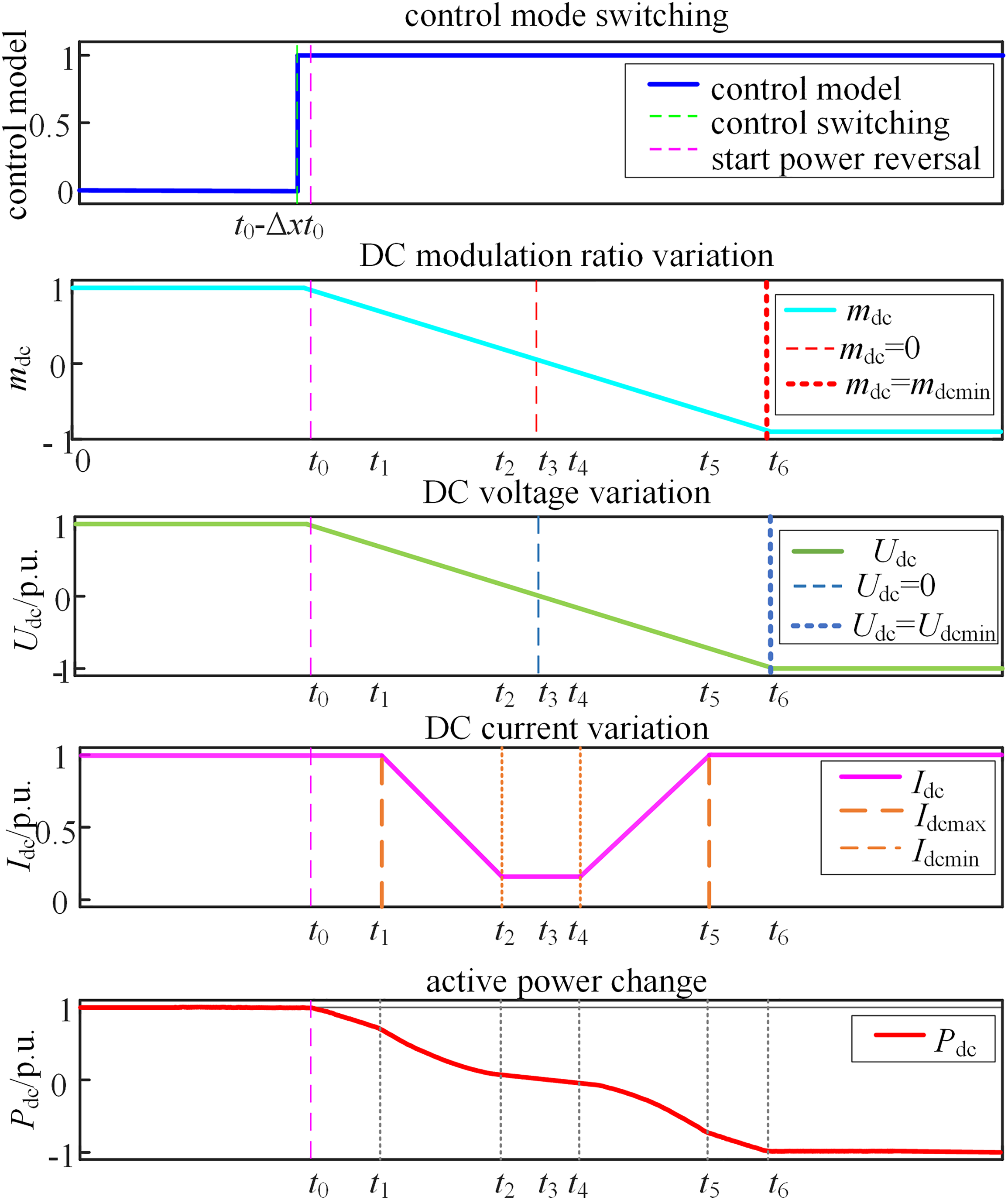
Figure 8: Timing diagram for power flow reversal control
Taking into account the operational needs of the MMC-CLCC hybrid system, the process for managing power flow reversal in the power flow reversal control process, as shown in Fig. 9.
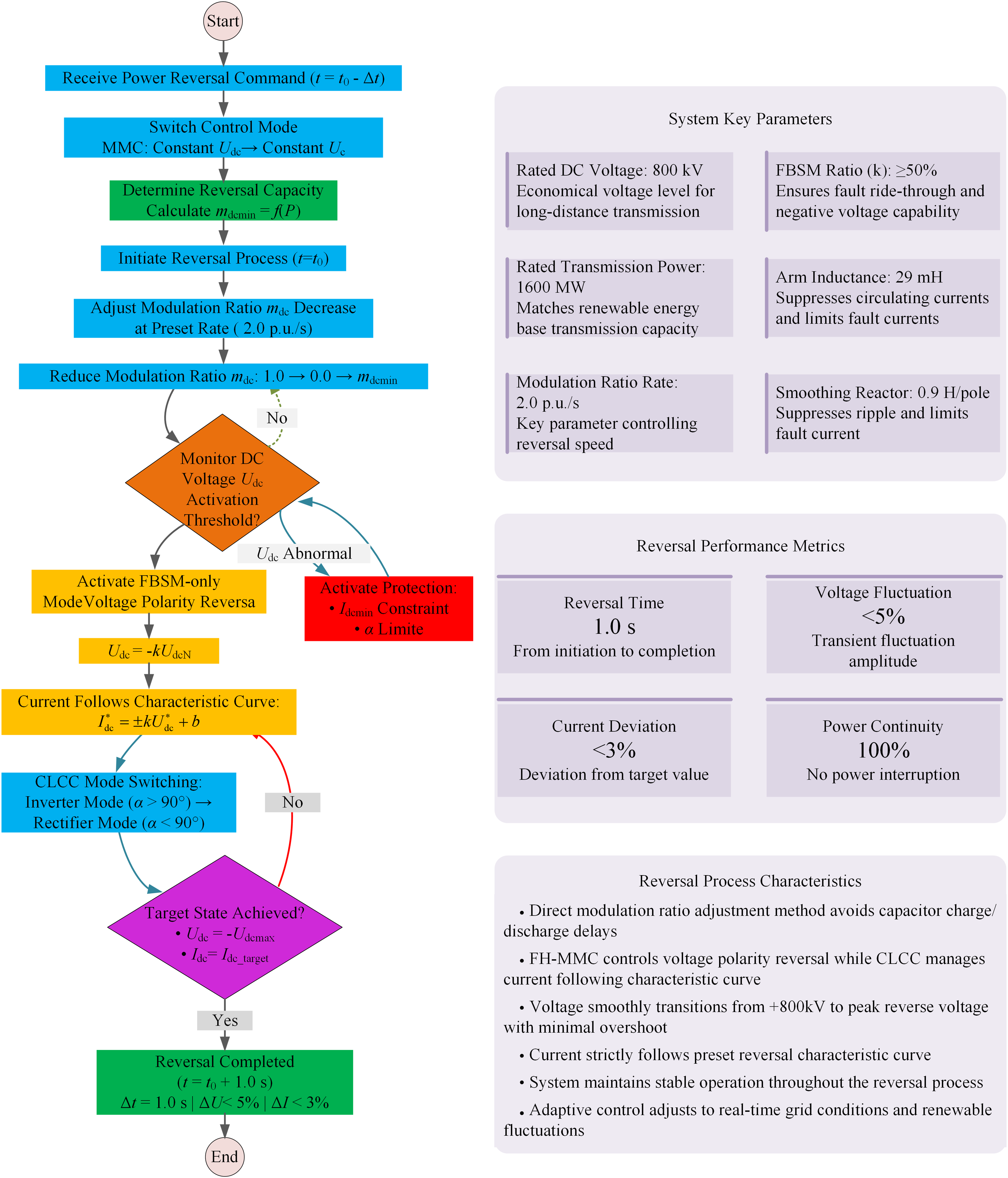
Figure 9: Implementation process of power flow reversal control
5 Simulation Results and Performance Validation
A comprehensive simulation model of the MMC-CLCC hybrid DC transmission system depicted in Fig. 1 has been developed in PSCAD/EMTDC, using the system parameters outlined in Section 2.3 (see Table 1 for specifics). All essential parameters (including converter station topology configuration, line parameters, and control logic) strictly follow the design values in Table 1 to verify the dynamic performance of the proposed power reversal strategy, especially in scenarios with a high proportion of full bridge submodules.
Power flow reversal characteristics were comparatively analyzed for hybrid topologies with FBSM ratios ranging from 50% to 100% in 5% increments. At t = 1.0 s, the reversal process commenced with mdc decreasing at 2.0 p.u./s. System response details are illustrated in Fig. 10, with subfigures (a)–(f) presenting DC voltage, DC current, trigger angle, active power, AC voltage and submodule capacitance voltage, respectively.

Figure 10: Dynamic response during power reversal under different FBSM ratios (k)
As shown in Fig. 10, the DC voltage (Fig. 10a) transitions linearly from +800 to −k*800 kV at a steady rate of 2.0 p.u./s, achieving polarity reversal within 1.0 s with transient fluctuations rigorously bounded within <5%. DC current (Fig. 10b) adheres strictly to the predefined characteristic curve
This research introduces a hybrid MMC-CLCC HVDC transmission system topology along with its online power flow reversal control strategy, leading to the following conclusions:
1) The MMC-CLCC hybrid system integrates MMC’s renewable energy support capability with CLCC’s commutation failure immunity and cost-effectiveness through a dedicated FB-HB submodule configuration (Section 2.1.2). This combination provides a novel technical solution for large-scale renewable energy transmission to load center regions through DC systems.
2) A methodology for selecting full-bridge/half-bridge submodule ratios in the sending-end MMC is developed, effectively addressing power flow reversal requirements between sending and receiving systems.
3) Leveraging FHMMC’s negative voltage operation capability, the proposed online power flow reversal strategy avoids power interruptions inherent in conventional reversal methods that require DC blocking before polarity reversal. The process achieves smooth and rapid power flow reversal, enhancing operational flexibility for renewable-rich grids.
Acknowledgement: We are very grateful for the support and cooperation of Northeast Electric Power University.
Funding Statement: This work is supported by Science and Technology Project of the headquarters of the State Grid Corporation of China (No. 5500-202324492A-3-2-ZN).
Author Contributions: The authors confirm contribution to the paper as follows: study conception and design: Yechun Xin, Xinyuan Zhao; data collection: Dong Ding, Shuyu Chen; analysis and interpretation of results: Chuanjie Wang; draft manuscript preparation: Tuo Wang. All authors reviewed the results and approved the final version of the manuscript.
Availability of Data and Materials: This article does not involve data availability, and this section is not applicable.
Ethics Approval: Not applicable.
Conflicts of Interest: The authors declare no conflicts of interest to report regarding the present study.
References
1. Hao J, Gao F, Fang X, Nong X, Zhang Y, Hong F. Multi-factor decomposition and multi-scenario prediction decoupling analysis of China’s carbon emission under dual carbon goal. Sci Total Environ. 2022;841:156788. doi:10.1016/j.scitotenv.2022.156788. [Google Scholar] [PubMed] [CrossRef]
2. Jia X, Zhang Y, Tan RR, Li Z, Wang S, Wang F, et al. Multi-objective energy planning for China’s dual carbon goals. Sustain Prod Consum. 2022;34(12):552–64. doi:10.1016/j.spc.2022.10.009. [Google Scholar] [CrossRef]
3. Liu L, Wang X, Wang Z. Recent progress and emerging strategies for carbon peak and carbon neutrality in China. Greenhouse Gases. 2023;13(5):732–59. doi:10.1002/ghg.2235. [Google Scholar] [CrossRef]
4. Rehman B, Rehman AU, Khan WA, Sami I, Ro JS. Operation and challenges of multi-infeed LCC-HVDC system: commutation failure, AC/DC power flow, and voltage stability. Appl Sci. 2021;11(18):8637. doi:10.3390/app11188637. [Google Scholar] [CrossRef]
5. Medina C, Ríos CM, Guadalupe González A. Transmission grids to foster high penetration of large-scale variable renewable energy sources—a review of challenges, problems, and solutions. Int J Renew Energy Res (IJRER). 2022;12(1):146–69. doi:10.20508/ijrer.v12i1.12738.g8400. [Google Scholar] [CrossRef]
6. Xue Y, Zhang XP. Reactive power and AC voltage control of LCC HVDC system with controllable capacitors. IEEE Trans Power Syst. 2017;32(1):753–64. doi:10.1109/TPWRS.2016.2557342. [Google Scholar] [CrossRef]
7. Daryabak M, Filizadeh S, Jatskevich J, Davoudi A, Saeedifard M, Sood VK, et al. Modeling of LCC-HVDC systems using dynamic phasors. IEEE Trans Power Deliv. 2014;29(4):1989–98. doi:10.1109/TPWRD.2014.2308431. [Google Scholar] [CrossRef]
8. Xue Y, Zhang XP, Yang C. Commutation failure elimination of LCC HVDC systems using thyristor-based controllable capacitors. IEEE Trans Power Deliv. 2018;33(3):1448–58. doi:10.1109/TPWRD.2017.2776867. [Google Scholar] [CrossRef]
9. Hou L, Zhang S, Wei Y, Zhao B, Jiang Q. A dynamic series voltage compensator for the mitigation of LCC-HVDC commutation failure. IEEE Trans Power Deliv. 2021;36(6):3977–87. doi:10.1109/TPWRD.2021.3052565. [Google Scholar] [CrossRef]
10. Beddard A, Barnes M. Modelling of MMC-HVDC systems—an overview. Energy Proc. 2015;80:201–12. doi:10.1016/j.egypro.2015.11.423. [Google Scholar] [CrossRef]
11. Gharaghani F, Asadi M. Control of MMC-HVDC transmission system: a review on internal and external converter control under grid strength. Electr Eng. 2023;105(6):3861–79. doi:10.1007/s00202-023-01908-1. [Google Scholar] [CrossRef]
12. Bex L, Liu X, Leterme W, Judge P, Hertem DV. Voltage support and electrical stresses in MMC-HVDC systems during AC faults. In: 2023 IEEE PES Innovative Smart Grid Technologies Europe (ISGT EUROPE); 2023 Oct 23–26; Grenoble, France. p. 1–5. doi:10.1109/ISGTEUROPE56780.2023.10407419. [Google Scholar] [CrossRef]
13. Hossain MI, Shafiullah M, Al-Sulaiman FA, Abido MA. Comprehensive analysis of PV and wind energy integration into MMC-HVDC transmission network. Sustainability. 2023;15(1):253. doi:10.3390/su15010253. [Google Scholar] [CrossRef]
14. Gao C, Yang J, He Z, Tang G, Zhang J, Li T, et al. Novel controllable-line-commutated converter for eliminating commutation failures of LCC-HVDC system. IEEE Trans Power Deliv. 2023;38(1):255–67. doi:10.1109/TPWRD.2022.3183599. [Google Scholar] [CrossRef]
15. Zhao J, Xu K, Li W. Research on the power coordinate control strategy between a CLCC-HVDC and a VSC-HVDC during the AC fault period. Energies. 2024;17(17):4478. doi:10.3390/en17174478. [Google Scholar] [CrossRef]
16. Shu HC, Zhao HF, Zhang X, Dong HF, Chen N, Bo ZQ. Reliability analysis of main electrical connection for sending-end converter station in kunliulong hybrid DC project of China. Autom Electr Power Syst. 2021;45:115–23. (In Chinese). doi:10.7500/AEPS20210308002. [Google Scholar] [CrossRef]
17. Dong Z, Zhang J, Wang G, Xu Z, Li J, Huang Z. Analysis of AC fault ride-through characteristics of the Baihetan-Jiangsu hybrid cascaded UHVDC system. In: 2021 International Conference on Power System Technology (POWERCON); 2021 Dec 8–9; Haikou, China. p. 1471–5. doi:10.1109/POWERCON53785.2021.9697810. [Google Scholar] [CrossRef]
18. Zhou L, Nian H, Liu H, Yang J, Luan H, Niu Y, et al. Research and engineering application of controllable line commutated converter valve-control system. In: 2024 International Conference on HVDC (HVDC); 2024 Aug 8–9; Urumqi, China. p. 574–9. doi:10.1109/HVDC62448.2024.10723001. [Google Scholar] [CrossRef]
19. Zheng W, Chen Y, Xue Y, Mao W, Xu S, Chen M. The enlightenment of online power reversal of line-commutated converter high voltage direct current for new power system. Automat Elect Power Syst. 2025;49(1):183–92. (In Chinese). doi:10.7500/AEPS20240426008. [Google Scholar] [CrossRef]
20. Zhang N, Xu Z, Zhang ZR. Receiving-end AC system fault ride-through control strategy of LCC-FHMMC hybrid HVDC transmission system. Electr Power Autom Equip. 2023;43(4):39–45,53. (In Chinese). doi:10.16081/j.epae.202210019. [Google Scholar] [CrossRef]
Cite This Article
 Copyright © 2026 The Author(s). Published by Tech Science Press.
This work is licensed under a Creative Commons Attribution 4.0 International License , which permits unrestricted use, distribution, and reproduction in any medium, provided the original work is properly cited.
 Downloads
 Citation Tools