
 Submit a Paper
 Propose a Special lssue
 Open Access
ARTICLE
Coordinated Source–Network–Storage Inertia Control Strategy Based on Wind Power Transmission via MMC-HVDC System
1 Central China Branch of State Grid Corporation of China, State Grid Corporation of China, Wuhan, 430077, China
2 State Key Laboratory of Disaster Prevention and Reduction for Power Grid (School of Electrical and Information Engineering), Changsha University of Science and Technology, Changsha, 410114, China
* Corresponding Author: Xingyu Shi. Email:
Energy Engineering 2026, 123(1), 23 https://doi.org/10.32604/ee.2025.069915
Received 03 July 2025; Accepted 22 August 2025; Issue published 27 December 2025
 View Full Text
 Download PDF
Abstract
In wind power transmission via modular multilevel converter based high voltage direct current (MMC-HVDC) systems, under traditional control strategies, MMC-HVDC cannot provide inertia support to the receiving-end grid (REG) during disturbances. Moreover, due to the frequency decoupling between the two ends of the MMC-HVDC, the sending-end wind farm (SEWF) cannot obtain the frequency variation information of the REG to provide inertia response. Therefore, this paper proposes a novel coordinated source-network-storage inertia control strategy based on wind power transmission via MMC-HVDC system. First, the grid-side MMC station (GS-MMC) maps the frequency variations of the REG to direct current (DC) voltage variations through the frequency mapping control, and uses submodule capacitor energy to provide inertial power. Then, the wind farm-side MMC station (WF-MMC) restores the DC voltage variations to frequency variations through the frequency restoration control and power loss compensation, providing real-time frequency information for the wind farm. Finally, based on real-time frequency information, the wind farm utilizes the rotor kinetic energy and energy storage to provide fast and lasting power support through the wind-storage coordinated inertia control strategy. Meanwhile, when the wind turbines withdraw from the inertia response phase, the energy storage can increase the power output to compensate for the power deficit, preventing secondary frequency drops. Furthermore, this paper uses small-signal analysis to determine the appropriate values for the key parameters of the proposed control strategy. A simulation model of the wind power transmission via MMC-HVDC system is built in MATLAB/Simulink environment to validate and evaluate the proposed method. The results show that the proposed coordinated control strategy can effectively improve the system inertia level and avoid the secondary frequency drop under the load sudden increase condition.Keywords
As renewable energy sources represented by wind power continue to develop, the traditional fossil energy system is gradually being replaced. At the same time, due to the uneven distribution of energy resources and power loads, the development of MMC-HVDC has been accelerating. However, large-scale wind power integration into the grid via MMC-HVDC can negatively impact the frequency stability of the receiving-end alternating current (AC) systems. First, under traditional control, MMC-HVDC cannot provide inertia support [1]. Second, the decoupling characteristic of MMC-HVDC at both ends prevents the SEWF from sensing frequency changes in the REG to provide inertia support [2]. Finally, even if the wind turbines utilize rotor kinetic energy to participate in the system’s inertia response, they are unable to provide long-term power support. Moreover, when the rotor speed of the wind turbines reaches its limit and they withdraw from the inertia response phase, secondary frequency drops are likely to occur [3].
To address the issue that flexible DC transmission systems with traditional control cannot provide inertia response, many researchers have conducted studies on using capacitors in flexible DC transmission systems for inertia support [4–6]. Ref. [1] coupled the AC frequency with the DC voltage and utilized the energy stored in the DC capacitors of the voltage source converter based high voltage direct current transmission (VSC-HVDC) systems by regulating the DC voltage. However, this method has high requirements for the configuration of DC capacitors and has not discussed its application to MMC-HVDC. In fact, the submodule capacitors in MMC stations contain a large amount of electrostatic energy for inertial support [4]. Therefore, Refs. [5,6] proposed an energy-frequency droop control applied to MMC, and the results show that when the number of levels in MMC stations is sufficiently high, substantial inertial support power can be provided solely using the energy storage in the submodule capacitors. However, relying solely on the capacitor energy in the flexible DC transmission systems to increase the system inertia level is not the optimal choice. Effectively utilizing the rotor kinetic energy of the wind turbines at the SEWF can further enhance the system’s inertial support capability.
In order to overcome the barrier that the SEWF cannot respond to frequency variations in the REG due to the decoupling of the MMC-HVDC systems, coordinated control between the SEWF and MMC-HVDC is required, either through communication-based or non-communication-based methods [7–9]. Ref. [7] proposed a communication-based coordinated control strategy that transmits frequency signal from the REG to the SEWF through a communication channel. This approach has a simple structure, but as the transmission distance increases, it leads to higher communication delays, which affect the dynamic performance and reliability of the control system, as well as increase investment costs [8]. Ref. [9] proposed a non-communication-based coordinated control strategy. On the grid side, the VSC station establishes a linear relationship between the REG frequency and the DC voltage through droop control. On the wind farm side, the VSC station restores the frequency information, enabling the SEWF to obtain frequency information. This method provides the necessary conditions for coordinating wind farms and MMC-HVDC to provide inertia support for the REG.
Based on the frequency information, the wind turbines can provide inertial support to the REG via MMC-HVDC using virtual inertia control strategies. Existing virtual inertia control strategies for wind turbines mainly include rotor kinetic energy control strategy [10,11] and wind turbine load shedding control strategy [12]. The rotor kinetic energy control strategy releases or absorbs rotor kinetic energy to provide inertia support during frequency variations. However, due to the limitations of the wind turbine rotor speed, this method cannot provide long-term power support, and it may lead to secondary frequency drops when the wind turbines withdraw from the inertia response phase [13]. The wind turbine load-shedding control strategy operates the wind turbine in a reduced-load mode by using overspeed control or pitch control, thereby retaining a certain power reserve to provide inertia response when the frequency changes [14,15]. However, under this control strategy, the wind turbines cannot operate in maximum power point tracking (MPPT) mode under steady-state conditions, leading to low wind energy utilization efficiency. Relying solely on the wind turbines can no longer meet the dual requirements of frequency regulation capability and resource utilization efficiency for the grid. Using energy storage to assist the wind turbines in participating in frequency regulation to compensate for their shortcomings is a promising approach [16,17]. Ref. [18] set the inertial response power based on the wind turbine torque limits, enabling the wind turbines to provide maximum active power output in a short term, with energy storage providing subsequent long-term power support. However, this approach was prone to causing frequency overshoot. Ref. [19] achieved inertia support across the full wind speed range by coordinating rotor kinetic energy and superconducting magnetic energy storage, while also preventing frequency oscillations and secondary frequency drops. Therefore, energy storage, with its fast response and flexibility, can effectively compensate for the shortcomings of wind turbines. It can assist wind turbines in providing sustained inertial power support and help prevent secondary frequency drops.
Unlike previous studies that used single-type inertia resources for inertia support, this paper proposes a coordinated source-network-storage inertia control strategy based on wind power transmission via MMC-HVDC system. The proposed strategy leverages the characteristics and advantages of wind turbines, energy storage, and MMC-HVDC, to achieve coordinated inertia support from heterogeneous inertia resources from the source, network, and storage, helping to address frequency variations in the REG. First, the GS-MMC uses the frequency mapping control strategy to map frequency variations of the REG to DC voltage variations. The change in DC voltage causes the submodule capacitors to release energy and provide inertial power. Then, based on the DC voltage variations of MMC-HVDC, the WF-MMC uses the frequency restoration control strategy and power loss compensation to achieve precise coupling between the REG and the SEWF frequencies, providing real-time frequency information to the SEWF. Finally, based on real-time frequency information, wind turbines and energy storage use the wind-storage coordinated inertia control strategy to simulate the inertia and droop characteristics of synchronous machines. Furthermore, when the wind turbines exits the inertia response phase and leads to a sudden drop in output power, the energy storage will increase power output to compensate for the power shortfall, preventing secondary frequency drops.
2 Structure and Control of Wind Farm Transmission via MMC-HVDC System
The structure of the wind power transmission via MMC-HVDC system studied in this paper is shown in Fig. 1. Its main components include the SEWF, WF-MMC, GS-MMC, and the REG. The SEWF includes multiple double-fed induction generators (DFIG) and battery energy storage systems (BESS).
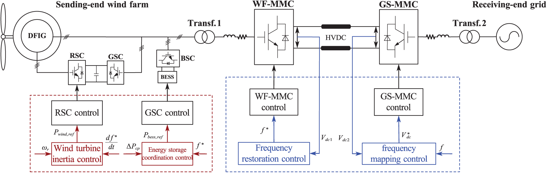
Figure 1: Topology and control strategy of wind power transmission via MMC-HVDC system
Traditional control strategies of this system are shown in the black part of Fig. 1. For DFIG, the rotor-side converter (RSC) typically operates in the maximum power point tracking (MPPT) control mode, while the grid-side converter (GSC) adopts DC voltage control to maintain the stability of the wind turbine’s DC voltage. The BESS is integrated into the grid via the energy storage converter (ESC), and it does not start when the system is operating normally. For MMC-HVDC, the WF-MMC uses fixed frequency and fixed AC voltage control to supply a stable network voltage for the wind farm; the GS-MMC uses fixed DC voltage and fixed reactive power control to maintain the stability of DC voltage and reactive power of MMC-HVDC. Wind farm and MMC-HVDC cannot directly provide inertia support to the REG under traditional control strategies.
3 Coordinated Source-Network-Storage Inertia Control Strategy for Wind Power Transmission via MMC-HVDC System
To address the issues that the SEWF and MMC-HVDC cannot directly provide inertia support to the disturbed REG, as well as the inability of wind turbines to sustain long-term power support and their tendency to cause secondary frequency drops, this paper proposes a solution by combining frequency information transmission with wind-storage coordinated inertia control in a coordinated control strategy. The wind-storage coordinated inertia control mainly consists of three control loops: Wind Turbine Inertia Control (WTIC), Energy Storage Droop Control (ESDC), and Energy Storage Power Compensation Control (ESPC).
3.1 Frequency Information Transmission Based on Frequency Mapping and Restoration
When the system frequency varies, MMC-HVDC can provide inertia support to the REG by absorbing or releasing energy through the submodule capacitors. If the MMC stations at both ends of the HVDC link are identically configured, the energy stored in their stations will be the same. The capacitors of all submodules in the MMC-HVDC system can be represented by an equivalent capacitor
where
By modulating the charging and discharging of the submodule capacitors’ voltage, the inertia response of the synchronous machine can be simulated. The derivation process is as follows.
The rotor motion equation of the synchronous machine can be expressed as:
where
The power dynamic response characteristics of MMC-HVDC are:
where
By solving Eqs. (2) and (3), the coupling relationship between DC voltage and AC frequency is established in the GS-MMC, allowing frequency variations to be mapped to DC voltage variations, and the electrostatic power of the submodule capacitors can provide inertia support.
where
where
After mapping the frequency variation to the DC voltage variation, the DC voltage value of MMC-HVDC is as follows:
As shown in Fig. 2, during the simulation of the inertia response, the DC voltage and AC frequency are coupled and positively correlated. When frequency variations in the REG cause changes in the DC voltage, the voltage changes cause the submodule capacitors to absorb or release energy accordingly, thereby providing inertia support.

Figure 2: MMC-HVDC frequency mapping control strategy
Based on Eq. (6), the coupling relationship between AC frequency and DC voltage can be expressed as:
For long-distance power transmission, the accuracy of frequency information restoration is ensured through line power loss compensation. The relationship between the DC voltages measured at both ends is as follows:
where
By solving Eqs. (7) and (8), the real-time frequency value of the sending-end grid can be expressed as:
As shown in Fig. 3, a frequency restoration control strategy is designed in the WF-MMC to couple the sending-end and receiving-end grid frequencies, thereby enabling the SEWF to respond to frequency variations at the receiving end.

Figure 3: MMC-HVDC frequency restoration control strategy
3.2 Coordinated Inertia Control Strategy of Wind-Storage Based on Real-Time Frequency Information
By using the real-time frequency information transmitted by MMC-HVDC, the wind farm can sense frequency variations in the REG and perform inertia response. To address the limitations of traditional inertia control strategies in wind turbines, this section proposes a wind-storage coordinated inertia control strategy that enhances the wind farm’s ability to provide sustained power support and prevents secondary frequency drops.
As shown in Figs. 4 and 5, under regular operating conditions, the DFIG operate in MPPT mode; the switch

Figure 4: Wind turbine power-speed change curve

Figure 5: Wind turbine inertia control strategy
It should be noted that
According to Eq. (11), the rotor speed at the moment when the DFIG exits the inertia response can be determined, which is also the moment when energy storage starts power compensation.
The limitation of the DFIG’s rotor kinetic energy in providing long-term support power can be addressed by using energy storage devices, enabling the wind farm to simulate the droop characteristics of synchronous generators, thereby providing sustained power support. In addition, when the DFIG exits the inertia response phase, the output power will drop sharply, the power output of the BESS can be properly controlled to compensate for this power deficit, effectively preventing secondary frequency drops.
As shown in Fig. 6, during normal steady-state operation, the energy storage output active power is zero and does not participate in system frequency regulation. When the system frequency deviation exceeds the threshold and the state of charge (SOC) of the energy storage is within limit range
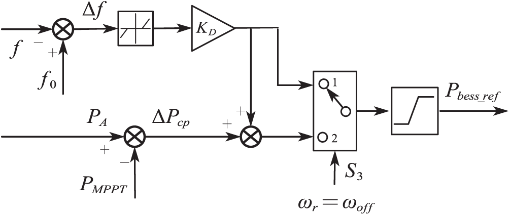
Figure 6: Energy storage coordination control strategy
When the DFIG exits the inertia response phase, its operating state drops from point C to point D, entering the rotor speed recovery phase. During this period, its active power output suddenly decreases, resulting in a power deficit. The switch
At this time, the value of the output active power of the BESS is:
The compensation power
3.3 Coordinated Source-Network-Storage Inertia Control Strategy Implementation Process
In summary, as shown in Fig. 7, the coordinated source-network-storage inertia control strategy based on wind farm transmission via MMC-HVDC system proposed in this paper mainly comprises the following control processes:

Figure 7: Coordinated inertia control strategy process
(1) GS-MMC frequency-voltage mapping: Based on the real-time frequency variation information measured at the grid connection point of the REG, the GS-MMC maps the AC frequency variations to DC voltage amplitude changes through frequency-voltage mapping. During this process, the submodule capacitors release their stored electrostatic energy to provide inertia support.
(2) WF-MMC voltage-frequency restoration: Based on the DC voltage variation information of the MMC-HVDC system, the WF-MMC precisely restores the DC voltage variations to frequency variations through voltage-frequency restoration control and power loss compensation, thereby achieving the frequency coupling between the REG and the SEWF, and providing real-time frequency information to the wind turbines and energy storage.
(3) Wind-storage coordinated inertia response: Based on real-time frequency information, the wind farm senses frequency variations in the REG, and the wind turbines release rotor kinetic energy through WTIC to provide inertia response, thereby suppressing the RoCoF. Meanwhile, energy storage releases energy through ESDC to provide droop response and sustained power support. When the DFIG exits the inertia response phase, the BESS switches to ESPC mode and increases active power output to compensate for the power deficit, thereby preventing secondary frequency drops.
4 Parameter Design and Stability Analysis
The existing global frequency safety warning value usually limits the maximum frequency change rate to within ±1 Hz/s [20], while the frequency operation deviation of the power system, considering the grid operation specifications and under-frequency load reduction protection, needs to be controlled within ±0.02 pu (±1 Hz) [21]. For MMC-HVDC, when the submodule capacitor energy is used to provide frequency support, the capacitor voltage variation range limit is
4.2 Small Signal Stability Analysis
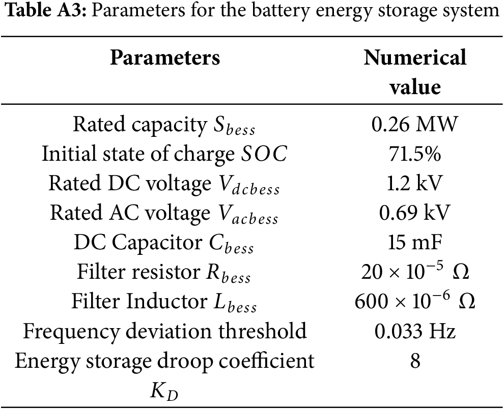
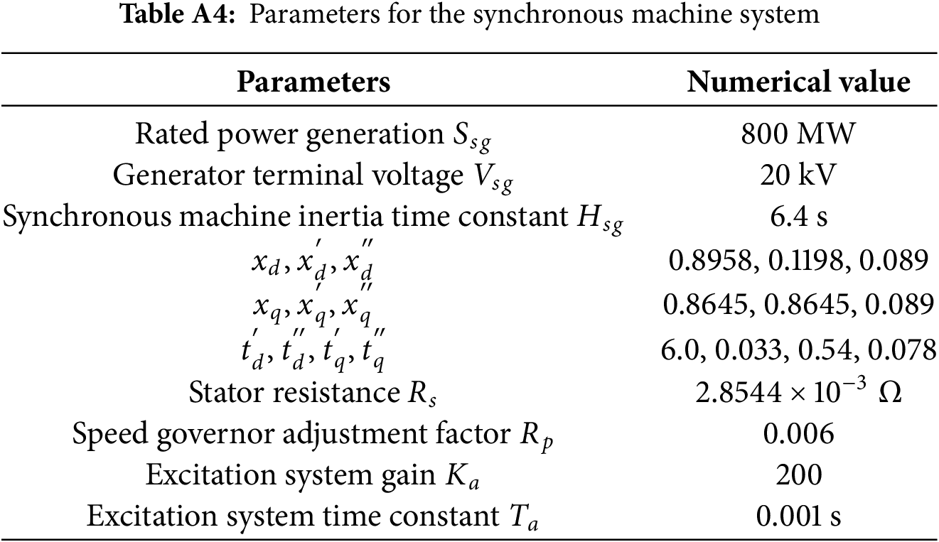
This section establishes a small signal model based on the wind power transmission via MMC-HVDC system shown in Fig. 1 and performs stability analysis on it. The wind farm consists of multiple DFIGs equipped with energy storage (using a single-machine equivalent model [19]), which are connected to the MMC-HVDC system through a transformer and then connected to the REG via another transformer (the REG is represented by a synchronous generator). The system parameters can be found in Tables A1–A4 in Appendix A. Detailed modeling can be found in [21,25,26]. The linear state-space model around the steady-state operating point can be extracted using the Linear Analysis Tool in the MATLAB/Simulink platform. The linearized small-signal model’s state-space equations can be expressed as:
where
The small-signal model of the wind power transmission via MMC-HVDC system proposed in this paper is mainly divided into four key modules: DFIG, BESS, MMC-HVDC system, and the REG. The three key parameters affecting the system’s inertia level, namely the virtual inertia time constant
As shown in Fig. 8a, when the virtual inertia time constant
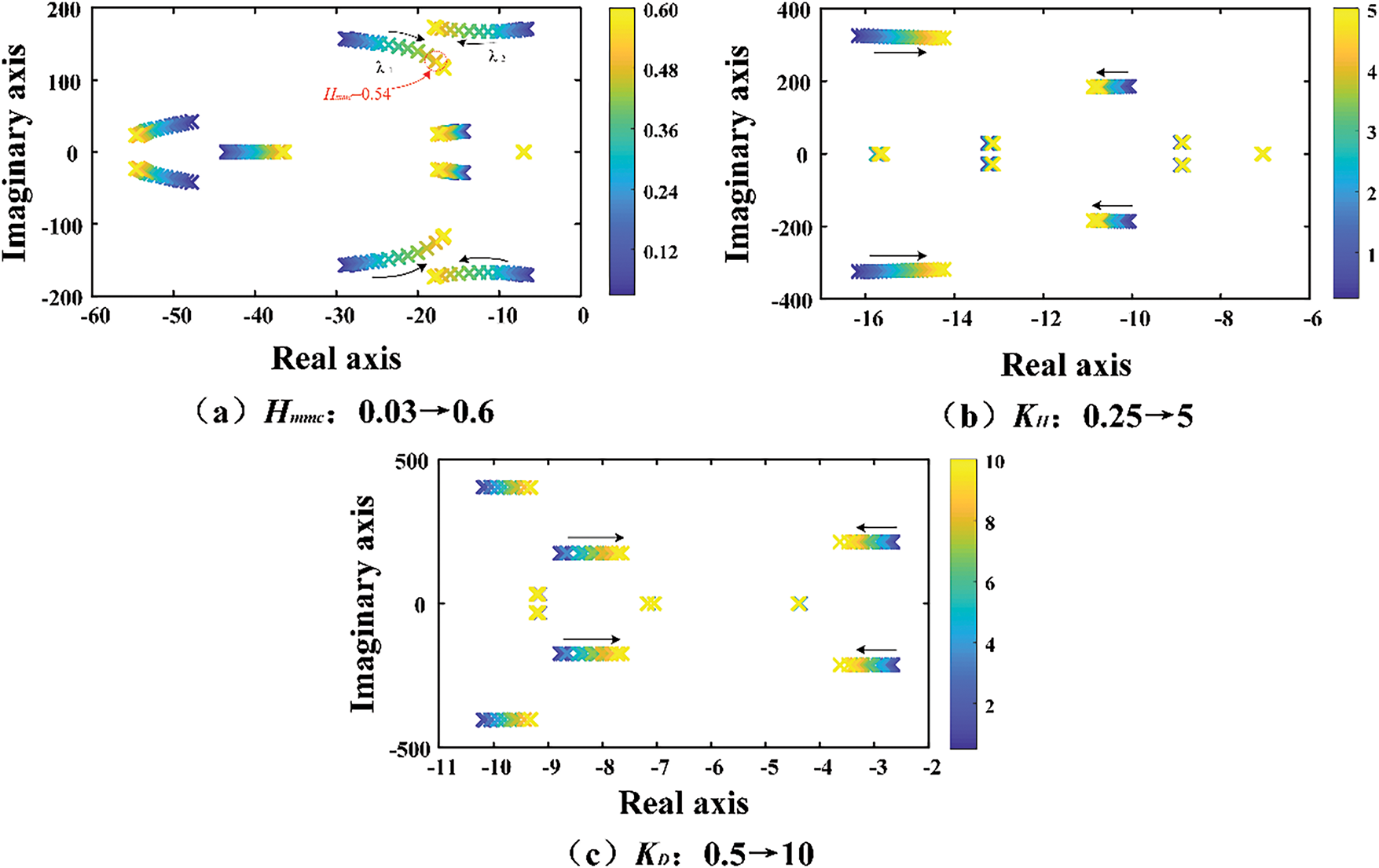
Figure 8: Eigenvalues locus of the system with control parameters varying
5.1 Simulation Test Scenario Settings
In order to test the performance of the proposed coordinated source-network-storage inertia control strategy for wind farm transmission via MMC-HVDC system, this paper first establishes a four-machine two-area system simulation model on the MATLAB/Simulink platform in order to evaluate the performance of the wind-storage coordinated inertia control strategy in enhancing the inertia support capacity of the wind farm and preventing secondary frequency drops. Then, a wind farm transmission via MMC-HVDC system simulation model was developed to validate the proposed coordinated source-network-storage inertia control strategy in providing inertia support to the REG and improving the overall system inertia level.
5.2 Simulation Verification of Inertia-Coordinated Control Strategy for Wind-Storage System in a Four-Machine Two-Area System
As shown in Fig. 9, in order to simulate the instantaneous power imbalance during a sudden load increase in the power system, a switchable load

Figure 9: Simulation test system of four-machine two-area
As shown in Fig. 10, under the sudden load increase condition, traditional wind turbines without additional control essentially do not respond. After the wind turbines are equipped with WTIC, they instantaneously increase the inertial power to provide inertia response, suppressing frequency variations and improving the minimum point of the first frequency drop. However, when the wind turbines exit the inertia response phase, the wind farm’s output power sharply decreases by 0.067 pu, followed by a secondary frequency drop in the system.
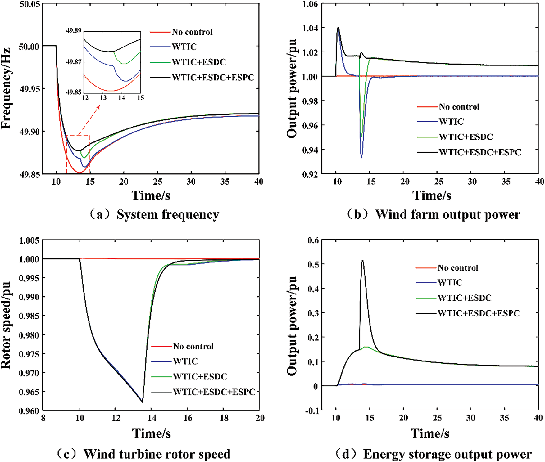
Figure 10: Dynamic response of wind farm system under different control strategies
On this basis, when ESDC is added to the energy storage, the wind farm can continuously provide approximately 0.01 pu of power support, which further improves the minimum point of the first frequency drop and the steady-state frequency deviation. However, it cannot prevent the secondary frequency drop. Therefore, by additionally adding ESPC to the energy storage, when the wind turbines exit the inertia response phase, the energy storage increases the power output to compensate for the power deficit, thereby preventing the secondary frequency drop.
It can be seen that under the wind-storage coordinated inertia control strategy, not only can the phenomenon of secondary frequency drops be effectively avoided, but the inertia support capacity of the SEWF system can also be enhanced, while maintaining a fast rotor speed recovery rate for the wind turbines.
5.3 Simulation Verification of Inertia-Coordinated Control Strategy for Wind Power Transmission via MMC-HVDC System
As shown in Fig. 11, a switchable load
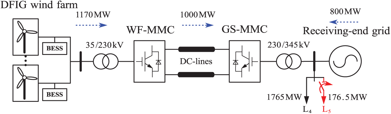
Figure 11: Simulation test system of wind farm transmission via MMC-HVDC system
As shown in Fig. 12, the accurate coupling of the frequencies at both ends of the MMC-HVDC system is achieved through frequency information transmission based on frequency mapping and restoration.
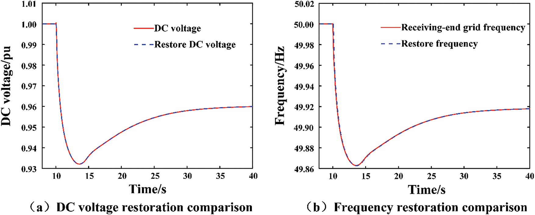
Figure 12: DC voltage and frequency restoration comparison
Under a sudden load increase, a comparative analysis is performed on the dynamic response variations of the wind farm connected via the MMC-HVDC systems under the following four control strategies: (1) Traditional control for source, network, and storage, without frequency regulation (Strategy 1); (2) MMC-HVDC frequency information transmission, with inertia support at the network side and frequency information transfer (Strategy 2); (3) MMC-HVDC frequency information transmission combined with wind turbine inertia control strategy, with coordinated inertia support from the source and network (Strategy 3); (4) MMC-HVDC frequency information transmission combined with wind turbine inertia control strategy and energy storage coordinated control strategy, with coordinated inertia support from the source, network, and storage (Strategy 4).
As shown in Fig. 13a,b, under the frequency information transmission of the MMC-HVDC system, the frequencies of the sending and receiving grids can be accurately coupled. Meanwhile, under the coordinated source-network-storage inertia control strategy, the wind turbines, energy storage devices, and MMC-HVDC work together to enhance the system’s inertia level, suppress the RoCoF, improve the minimum frequency point, and reduce the steady-state frequency deviation. As shown in Fig. 13c,d, the change in the DC voltage of MMC-HVDC causes the submodule capacitor voltage to change accordingly and releases energy for frequency support. Fig. 13e,f shows that the SEWF provides substantial inertial power to the REG via MMC-HVDC. The additional energy storage device, under the coordinated control strategy, also prevents the issue of secondary frequency drops caused by sudden power decreases. At the same time, it provides sustained power support, reducing the steady-state frequency deviation.
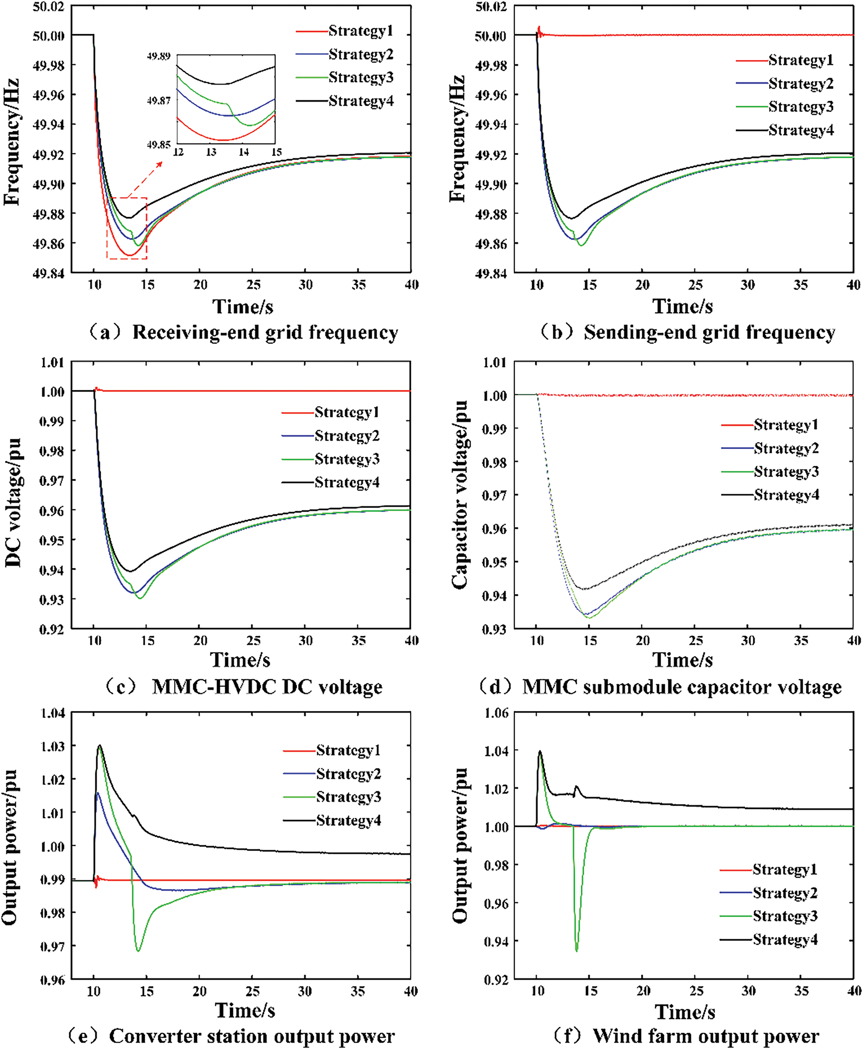
Figure 13: System dynamic response when load increases suddenly
Therefore, the coordinated source-network-storage inertia control strategy for wind farm transmission via MMC-HVDC system proposed in this paper can quickly and sustainably provide power support for frequency drops of the REG, effectively enhancing the overall inertia level of the system, and avoiding secondary frequency drops.
This paper proposes a coordinated source-network-storage inertia control strategy based on wind power transmission via MMC-HVDC systems, leveraging heterogeneous inertia resources across the source, network, and storage to enhance the overall system inertia level and ensure safe and stable operation. Compared with traditional methods, this proposed strategy offers the following advantages:
(1) Wind turbines possess substantial rotor kinetic energy that can participate in the system inertia support, Through WTIC, it can be used to simulate the inertia response characteristics of synchronous generators. Energy storage, characterized by its rapid response and flexibility, employs droop control to emulate the droop frequency modulation behavior of synchronous generators. The coordination of the two enables wind farms to rapidly suppress the system frequency change rate and provide sustained power support.
(2) For energy storage, additional power compensation control is introduced. When energy storage participates in system frequency regulation, its active power output mode is adjusted to compensate for the power shortage caused by the wind turbines exiting the inertia response, effectively avoiding secondary frequency drops.
(3) In GS-MMC, frequency-voltage mapping control is employed to map frequency variations of the receiving power grid to DC voltage variations, thereby utilizing the submodule capacitor energy to provide inertia support; in WF-MMC, voltage-frequency restoration control and power loss compensation are implemented to accurately restore voltage changes to frequency changes, so that the wind farm can obtain real-time frequency information and provide inertia support for the REG.
With the large-scale development of renewable energy and power electronic devices in the future, the demand for system inertia support will further increase. Research on inertia support capabilities should not be limited to single-type devices alone. Coordinated control using all available inertia resources within the system to enhance inertia support capability will be the future trend. The control strategy proposed in this paper leverages the characteristics and advantages of source-network-storage heterogeneous resources. Through MMC-HVDC, frequency information is transmitted, allowing the wind farm to sense frequency variations in the REG, and enables the submodule capacitors inside the MMC station to release energy to provide inertia support. By coordinating the use of wind turbine rotor kinetic energy and energy storage, the strategy provides rapid and sustained power support while effectively avoiding secondary frequency drops. It thus shows great potential for enhancing the overall inertia level of the power system and ensuring frequency stability in power systems.
Acknowledgement: None.
Funding Statement: This research was funded by State Grid Corporation of China Central Branch Technology Project (52140024000C).
Author Contributions: The authors confirm contribution to the paper as follows: Conceptualization, Mengxuan Shi and Xingyu Shi; methodology, Lintao Li and Xingyu Shi; validation, Lintao Li and Xingyu Shi; formal analysis, Dejun Shao and Xiaojie Pan; investigation, Dejun Shao and Xiaojie Pan; data curation, Mengxuan Shi; writing—original draft preparation, Lintao Li; writing—review and editing, Lintao Li and Yuxun Wang; visualization, Yuxun Wang; supervision, Xingyu Shi and Yuxun Wang; project administration, Xingyu Shi; funding acquisition, Mengxuan Shi. All authors reviewed the results and approved the final version of the manuscript.
Availability of Data and Materials: The raw data supporting the conclusion of this article will be made available by the authors with reasonable request.
Ethics Approval: Not applicable.
Conflicts of Interest: The authors declare no conflicts of interest to report regarding the present study.


References
1. Zhu J, Booth CD, Adam GP, Roscoe AJ. Inertia emulation control of VSC-HVDC transmission system. In: 2011 International Conference on Advanced Power System Automation and Protection; 2011 Oct; Beijing, China. p. 1–6. doi:10.1109/APAP.2011.6180514. [Google Scholar] [CrossRef]
2. Li Y, Xu Z, Østergaard J, Hill DJ. Coordinated control strategies for offshore wind farm integration via VSC-HVDC for system frequency support. IEEE Trans Energy Convers. 2017;32(3):843–56. doi:10.1109/TEC.2017.2663664. [Google Scholar] [CrossRef]
3. Zhou Z, Li H, Tan H. Coordinated frequency control strategy of offshore wind farm via MMC-HVDC considering secondary frequency drop. In: 2023 26th International Conference on Electrical Machines and Systems (ICEMS); 2023 Nov 5–8; Zhuhai, China. p. 1977–80. doi:10.1109/ICEMS59686.2023.10344365. [Google Scholar] [CrossRef]
4. Pan C, Yin T, Shi X, Lin L. An adaptive inertia support control strategy for modular multilevel converter. IEEE Trans Ind Electron. 2025:1–11. doi:10.1109/TIE.2025.3567643. [Google Scholar] [CrossRef]
5. Kim H, Kang J, Shim JW, Beerten J, Van Hertem D, Jung HJ, et al. Exploiting redundant energy of MMC–HVDC to enhance frequency response of low inertia AC grid. IEEE Access. 2019;7:138485–94. doi:10.1109/ACCESS.2019.2942852. [Google Scholar] [CrossRef]
6. Yang S, Fang J, Tang Y, Qiu H, Dong C, Wang P. Modular multilevel converter synthetic inertia-based frequency support for medium-voltage microgrids. IEEE Trans Ind Electron. 2019;66(11):8992–9002. doi:10.1109/TIE.2018.2890491. [Google Scholar] [CrossRef]
7. Wang W, Yin X, Cao Y, Jiang L, Li Y. A distributed cooperative control based on consensus protocol for VSC-MTDC systems. IEEE Trans Power Syst. 2021;36(4):2877–90. doi:10.1109/TPWRS.2021.3051770. [Google Scholar] [CrossRef]
8. Pipelzadeh Y, Chaudhuri B, Green TC. Inertial response from remote offshore wind farms connected through VSC-HVDC links: a communication-less scheme. In: 2012 IEEE Power and Energy Society General Meeting; 2012 Jul; San Diego, CA, USA. p. 1–6. doi:10.1109/PESGM.2012.6345609. [Google Scholar] [CrossRef]
9. Li Y, Zhang Z, Yang Y, Li Y, Chen H, Xu Z. Coordinated control of wind farm and VSC–HVDC system using capacitor energy and kinetic energy to improve inertia level of power systems. Int J Electr Power Energy Syst. 2014;59(4):79–92. doi:10.1016/j.ijepes.2014.02.003. [Google Scholar] [CrossRef]
10. Sun L, Yang P, Jiang H, Xu Y, Kang L, Lu X. Research on primary frequency regulation strategies for ancillary wind power inertia based on the rotor kinetic energy. Front Energy. 2023;10:969549. doi:10.3389/fenrg.2022.969549. [Google Scholar] [CrossRef]
11. Yang D, Xu Y, Zhu T, Wang Y, Cao Q, Ma Y, et al. Research on the impacts of the inertia and droop control gains from a variable-speed wind turbine generator on the frequency response. Energ Eng. 2022;119(2):539–54. doi:10.32604/ee.2022.015133. [Google Scholar] [CrossRef]
12. Ramtharan G, Jenkins N, Ekanayake JB. Frequency support from doubly fed induction generator wind turbines. IET Renew Power Gener. 2007;1(1):3–9. doi:10.1049/iet-rpg:20060019. [Google Scholar] [CrossRef]
13. Gowaid IA, El-Zawawi A, El-Gammal M. Improved inertia and frequency support from grid-connected DFIG wind farms. In: 2011 IEEE/PES Power Systems Conference and Exposition; 2011 Mar; Phoenix, AZ, USA. p. 1–9. doi:10.1109/PSCE.2011.5772589. [Google Scholar] [CrossRef]
14. Xu Y, Wang H, Yang D. An enhanced frequency response strategy of a DFIG based on over-speed de-loaded curve. Appl Sci. 2021;11(19):9324. doi:10.3390/app11199324. [Google Scholar] [CrossRef]
15. Zhu Y, Liu S, Wang W. Comprehensive coordinated control strategy of PMSG-based wind turbine for system inertia support. IET Renew Power Gener. 2021;15(9):1915–26. doi:10.1049/rpg2.12115. [Google Scholar] [CrossRef]
16. Shu H, Dong H, Wang G, Chen J, Shi B, Tang Y. Wind-storage coordinated control strategy for inertia enhancement of high ratio renewable energy power systems. J Energy Storage. 2024;97(9):112998. doi:10.1016/j.est.2024.112998. [Google Scholar] [CrossRef]
17. Chen J, Yuan T, Li X, Li W, Wang X. Research on coordinated control strategy of DFIG-ES system based on fuzzy control. Energies. 2023;16(12):4770. doi:10.3390/en16124770. [Google Scholar] [CrossRef]
18. Wu Z, Gao DW, Zhang H, Yan S, Wang X. Coordinated control strategy of battery energy storage system and PMSG-WTG to enhance system frequency regulation capability. IEEE Trans Sustain Energy. 2017;8(3):1330–43. doi:10.1109/TSTE.2017.2679716. [Google Scholar] [CrossRef]
19. Miao L, Wen J, Xie H, Yue C, Lee WJ. Coordinated control strategy of wind turbine generator and energy storage equipment for frequency support. IEEE Trans Ind Appl. 2015;51(4):2732–42. doi:10.1109/TIA.2015.2394435. [Google Scholar] [CrossRef]
20. Li G, Liu X, Xin Y, Jiang T, Yan K, Wang T. Research on frequency stability of power system with high penetration renewable energy: a review. High Volt Eng. 2024;50(3):1165–81. (In Chinese). doi:10.13336/j.1003-6520.hve.20232053. [Google Scholar] [CrossRef]
21. Zhu J, Shi M, Yu L, Zhao J, Bu S, Chung C, et al. Supercapacitor-based coordinated synthetic inertia scheme for voltage source converter-based HVDC integrated offshore wind farm. IET Energy Syst Integrat. 2024;6(1):5–17. doi:10.1049/esi2.12137. [Google Scholar] [CrossRef]
22. Zhang H, Xiang W, He Y, Wen J. Optimal energy utilization of MMC-HVDC system integrating offshore wind farms for onshore weak grid inertia support. IEEE Trans Power Syst. 2023;39(1):1304–18. doi:10.1109/TPWRS.2023.3239166. [Google Scholar] [CrossRef]
23. Zhang H, Xiang W, Wang Y, Wen J. Energy-utilizing frequency support for MMC-MTDC system integrating asynchronous grids. IEEE Trans Energy Convers. 2024;39(4):2591–604. doi:10.1109/TEC.2024.3389933. [Google Scholar] [CrossRef]
24. Yan X, Son Z, Cui S, Sun Y, Li T. Primary frequency regulation strategy of doubly-fed wind turbine based on variable power point tracking and supercapacitor energy storage. Trans China Electrotech Soc. 2020;35(3):530–41. (In Chinese). doi:10.19595/j.cnki.1000-6753.tces.190573. [Google Scholar] [CrossRef]
25. Zhu J, Shen Z, Bu S, Li X, Booth CD, Qiu W, et al. Coordinated flexible damping mechanism with inertia emulation capability for MMC-MTDC transmission systems. IEEE J Emerg Sel Top Power Electron. 2020;9(6):7329–42. doi:10.1109/JESTPE.2020.3025690. [Google Scholar] [CrossRef]
26. Sun D, Liu H, Gao S, Wu L, Song P, Wang X. Comparison of different virtual inertia control methods for inverter-based generators. J Mod Power Syst Clean Energy. 2020;8(4):768–77. doi:10.35833/MPCE.2019.000330. [Google Scholar] [CrossRef]
Cite This Article
 Copyright © 2026 The Author(s). Published by Tech Science Press.
This work is licensed under a Creative Commons Attribution 4.0 International License , which permits unrestricted use, distribution, and reproduction in any medium, provided the original work is properly cited.
 Downloads
 Citation Tools