
 Submit a Paper
 Propose a Special lssue
 Open Access
ARTICLE
Robust Sensor—Less PR Controller Design for 15-PUC Multilevel Inverter Topology with Low Voltage Stress for Renewable Energy Applications
1 Department of Electrical & Electronics Engineering, Sasi Institute of Technology & Engineering, Tadepalligudem, 534101, India
2 Department of Electrical & Electronics Engineering, Institute of Aeronautical Engineering, Dundigal, Hyderabad, 500043, India
3 Department of Electronics and Communication Engineering, Chadalawada Ramanamma Engineering College, Renigunta Road, Tirupati, 517506, India
4 Department of Computer Science & Technology, Sasi Institute of Technology & Engineering, Tadepalligudem, 534101, India
5 Department of Electronics and Communication Engineering, Mohan Babu University, Tirupathi, 517102, India
6 Deptartment of Electronics and Communication Engineering, Sasi Institute of Technology & Engineering, Tadepalligudem, 534101, India
* Corresponding Author: T. Venkatakrishnamoorthy. Email:
(This article belongs to the Special Issue: Advanced Analytics on Energy Systems)
Energy Engineering 2026, 123(1), 10 https://doi.org/10.32604/ee.2025.072982
Received 08 September 2025; Accepted 11 November 2025; Issue published 27 December 2025
 View Full Text
 Download PDF
Abstract
Conventional multilevel inverters often suffer from high harmonic distortion and increased design complexity due to the need for numerous power semiconductor components, particularly at elevated voltage levels. Addressing these shortcomings, this work presents a robust 15-level Packed U Cell (PUC) inverter topology designed for renewable energy and grid-connected applications. The proposed system integrates a sensor less proportional-resonant (PR) controller with an advanced carrier-based pulse width modulation scheme. This approach efficiently balances capacitor voltage, minimizes steady-state error, and strongly suppresses both zero and third-order harmonics resulting in reduced total harmonic distortion and enhanced voltage regulation. Additionally, a novel switching algorithm simplifies the design and implementation, further lowering voltage stress across switches. Extensive simulation results validate the performance under various resistive and resistive-inductive load conditions, demonstrating compliance with IEEE-519 THD standards and robust operation under dynamic changes. The proposed sensorless PR-controlled 15-PUC inverter thus offers a compelling, cost-effective solution for efficient power conversion in next-generation renewable energy systems.Keywords
Over the past decade, the rapid depletion of non-renewable energy resources has become a pressing issue due to increasing global power consumption. Power industries now face significant challenges in meeting this growing demand. Reports from the World Research Organization have highlighted how population growth and increased atmospheric pollutant emissions are intensifying environmental threats, including greenhouse effects and the accelerated melting of ice sheets. As a response, the adoption of renewable energy sources has become vital—not only for addressing environmental concerns but also for supporting energy needs in sectors like electric vehicles (EVs). Multilevel inverters (MLIs) are emerging as key technologies for achieving efficient power generation from solar, wind, and other renewables.
In modern power systems, industries are increasingly utilizing inverters for highly effective conversion across a range of applications, from low- and high-power standalone systems to grid-connected networks. However, grid integration introduces harmonic distortion, particularly under varying nonlinear loads. Conventional passive filters fall short in suppressing high-order harmonics from such loads. As a result, the advanced features of MLIs are increasingly being leveraged to mitigate these challenges and enhance the quality and efficiency of power conversion [1,2].
1. Lower order harmonics
2. High number of levels with low PSC
3. Transient outputs
4. Regulated with a lower to higher switching frequency
5. Minor switching losses
This research paper primarily focuses on the above-mentioned features using a traditional asymmetrical MLI. Asymmetrical MLIs can control higher-order harmonics with fewer power semiconductor components (PSC) for non-linear loads. The research particularly emphasizes a modified switching control algorithm with sensorless PR control for a 15-level PUC MLI.
In recent years, multilevel inverters (MLIs) have garnered significant attention in the power and electric vehicle (EV) sectors due to their unique advantages, including reduced harmonics, lower switching losses, and improved efficiency. Conventional MLI topologies, such as the Neutral Point Clamped (NPC) by Nabae et al., Flying Capacitor (FC) by Meynard et al., and Cascaded H-Bridge (CHB) by Peng et al., each present distinct control challenges [3]. Although level-shifted and space vector PWM techniques with closed-loop controllers can partially mitigate these issues, the FC topology often faces voltage balancing difficulties related to clamping capacitors, while CHB topology struggles with complexity due to the need for phase-shifting transformers and isolated DC sources. As a result, recent research has focused on asymmetrical and advanced MLI designs to overcome these drawbacks [4,5].
Asymmetrical MLI’s are control harmonics efficiently and those topologies have more levels with lower PSC. Packed U Cell (PUC) topologies offer low switching losses, reduced harmonics, and higher voltage levels with fewer power semiconductor components, making them ideal for modern grid and EV applications. Moreover, digital twin-driven IoT architectures have further improved the capability of such systems to monitor, diagnose, and optimize performance, especially for electrified vehicle platforms [6]. Consequently, advancements in sensorless control and digital integration are enhancing the reliability and efficiency of multilevel inverter systems for next-generation power electronic applications [7,8]. This work explores a modified switching algorithm and sensorless PR controller for the 15-level PUC inverter, aiming to control load voltage and current ripples using level-shifted PWM. The compact 15-PUC inverter is adaptable for medium to high-power systems, standalone operations, and EV platforms. Fig. 1 compares the semiconductor requirements for various conventional and PUC topologies, demonstrating that the 15-PUC design significantly minimizes the need for isolating transformers and bulky components, thereby reducing system costs [9].
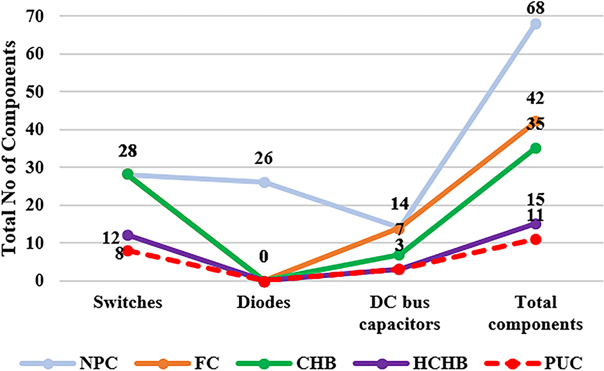
Figure 1: Power semiconductor components for 15-level inverters
The proposed 15-level Packed U Cell (15-PUC) inverter features a simplified architecture, utilizing only 11 components, 8 IGBT switches and 3 sources or capacitors unlike more complex conventional multilevel inverter designs. In this study, the 15-PUC inverter is operated using a level-shift pulse width modulation (PWM) technique alongside a sensorless proportional-resonant (PR) controller. The PR controller is shown, through stability analysis, to effectively suppress higher-order harmonics even at lower switching frequencies. Additionally, the 15-PUC is managed by a novel switching algorithm that further enhances performance and reliability.
Traditionally, researchers have managed PUC and other conventional multilevel inverter topologies using controllers such as PI, hysteresis, and various optimized strategies [10–12]. However, PI controllers exhibit significant drawbacks in DC-AC applications, including sluggish response to system disturbances, pronounced overshoot at startup, and sensitivity-dependent gain issues [13–16]. Hysteresis controllers, while simple to implement for MLIs, struggle to maintain constant amplitude and switching frequency, often resulting in bandwidth and tolerance errors [17,18]. Other linear and optimized controllers frequently encounter challenges such as capacitor voltage imbalance, zero and third-order harmonics, and persistent static and dynamic errors. To address these shortcomings, this paper proposes a simple and efficient sensorless PR controller for the 15-level PUC inverter [19,20]. The PR controller automatically balances capacitor voltages without relying on voltage or feedback sensors [21,22]. Fig. 2 illustrates the modulation methods employed for various MLI topologies, highlighting the use of different controllers to optimize renewable energy system performance. Furthermore, harmonic elimination approaches for MLIs are discussed in the context of advanced control techniques [23].

Figure 2: Modulation methods for MLI topologies
Accordingly, the structure of this paper is as follows: Section 2 details the novel switching algorithm and modeling of the 15-PUC multilevel inverter topology. Section 3 presents the advanced level-shift multicarrier-based SPWM approach. Section 4 introduces the sensorless PR voltage controller, integrated within both the PWM method and switching algorithm. Section 5 provides simulation results and performance comparison of the 15-PUC inverter. Section 6 concludes the paper and provides references, respectively.
2 Novel Switching Algorithm For 15-PUC MLI
In conventional switching sequence, power switches are unable to trigger simultaneously, and all switches are triggered in mode 8. (2–3) & (13–14) modes are quite opposite compared to novel switching. Following Table 1 represents the switching algorithm for 15-PUC MLI and it’s developed through 8 power semiconductor switches

The formula defines three distinct DC voltage levels used in a multilevel inverter system:
15-PUC MLI is represented in Fig. 3. By using the novel switching algorithm, the mode of operation with current flow direction is presented in Table 1.
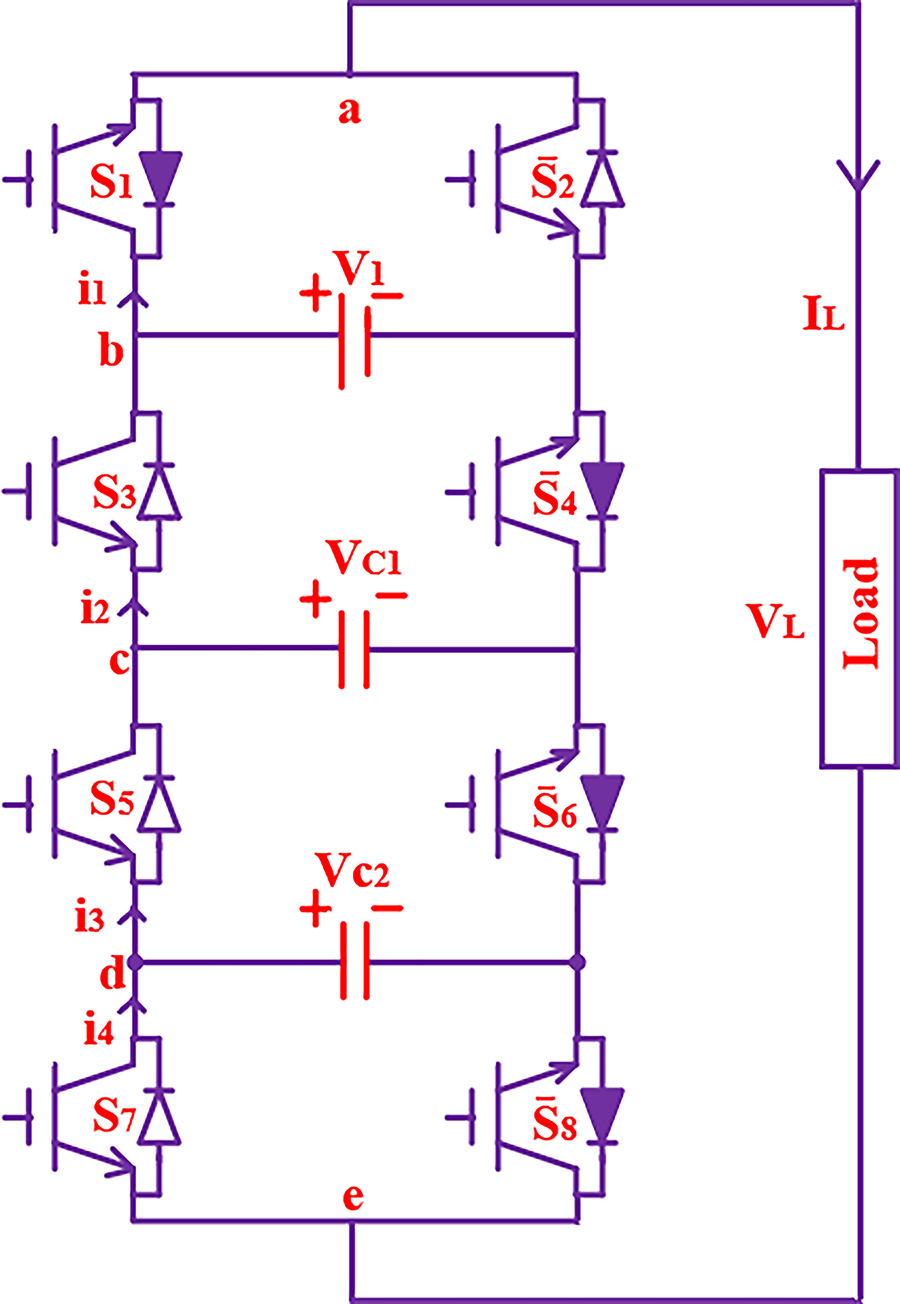
Figure 3: Single-phase 15-PUC MLI
The maximum voltage stress across the switches is important criteria for the MLI’s, this can be called as total standing voltage (TSV). It is equal to the maximum voltage across the switches. The Fig. 4 represents the voltage stress on switches

Figure 4: Voltage stress on semiconductor switches for 15-PUC MLI
The ratio of normalized voltage stress NVstrs is denoted by actual voltage stress Vstrs across switch with maximum voltage VLmax. This paper explains the voltage stress at each switch and normalized voltage stress shown in Table 2. Fig. 5 shows that the stress distribution of each switch has been presented.
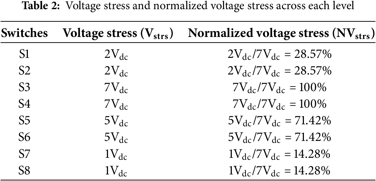
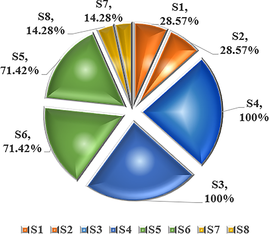
Figure 5: Voltage stress distribution of each switch
The TSV plays an major role in finding the cost function and efficiency of MLI. Its consists of all MBV values for the overall semiconductor devices in topology. In 15-PUC topology all switches are un-directional and one-leg is operating in complementary. Therefore, the TSV is determined using the following equation:
Hence the TSV is found to be 30Vdc, and the TSVpu is determined using the below equation:
The cost function (CF) analysis has been presented in this section for 15-PUC MLI topology. Many parameters are to be considered like no of switches Nsw, no of diodes Nd, no of capacitors Nc, no of voltage sources Nvs, no of driver circuits Ndc and TSVpu with the below equation:
In general, α to be considered either it should be lesser than 1 or greater than 1. Here authors considered 0.5 and 1.5 as the values of α for the optimal analysis. In the 15-PUC there are no diodes and capacitors hence it is neglected from the calculations. Further the component per level is to be determined using the equation
From the Table 3, the detailed analysis of CF for various MLI’s has been discussed with latest topologies and some conventional topologies.
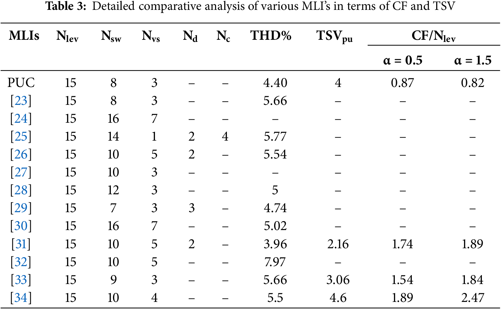
The detailed comparisons of various MLS’s has been presented in Figs. 6–12 in terms of no of switches, voltage sources, diodes, capacitors, TSVpu, THD% and CF/Nlev, respectively.

Figure 6: No of switches Nsw between PUC and recent MLI’s [23–34]
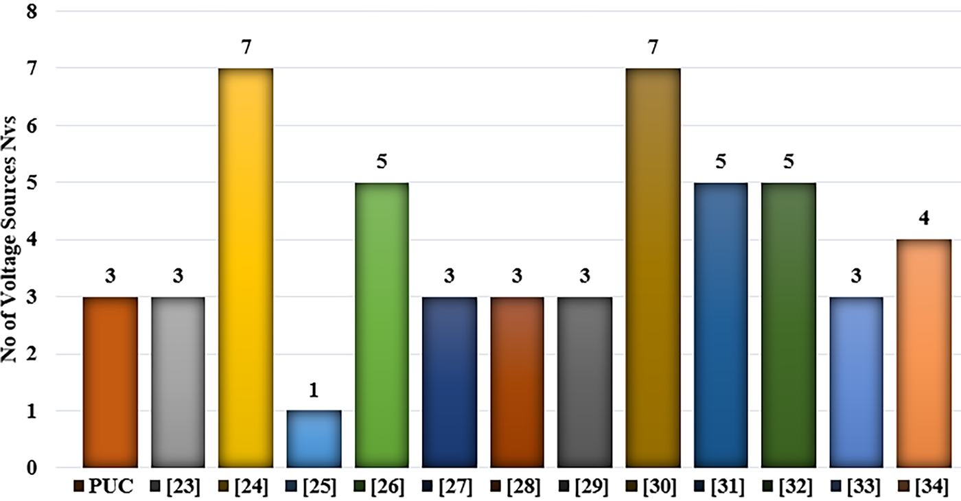
Figure 7: No of voltage sources Nvs between PUC and recent MLI’s [23–34]

Figure 8: No of diodes Nd between PUC and recent MLI’s [25,26,29,31]

Figure 9: No of capacitors Nc between PUC and recent MLI’s [25]
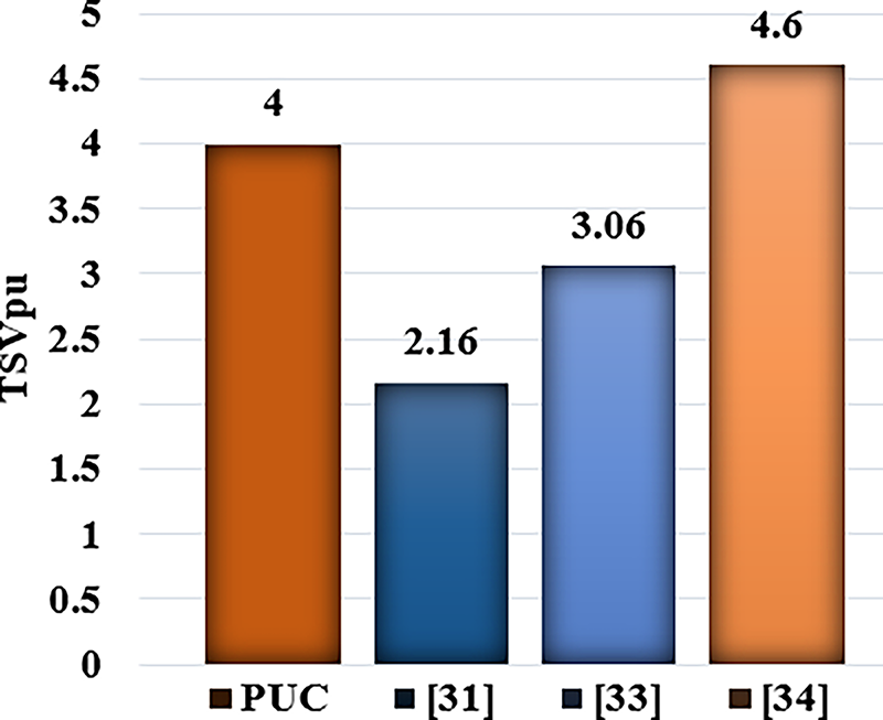
Figure 10: TSVpu between PUC and recent MLI’s [31,33,34]
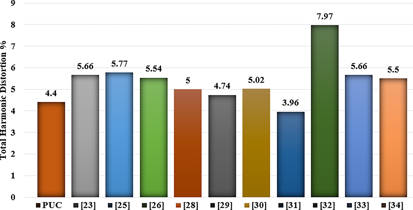
Figure 11: THD% between PUC and recent MLI’s [23,25,26,28–34]
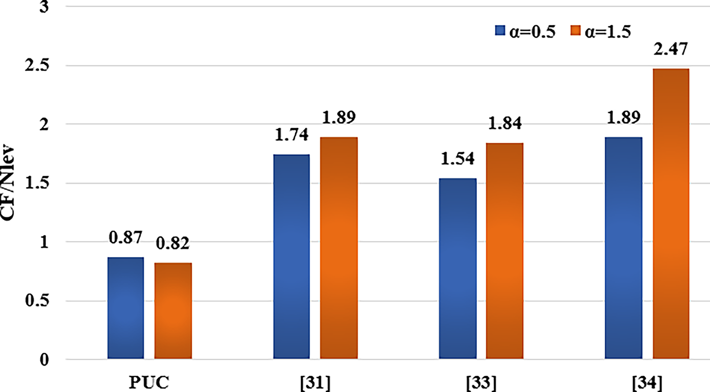
Figure 12: CF/Nlev between PUC and recent MLI’s [31,33,34]
3 Advanced Level Shift Multi-Carrier Based SPWM Technique
Multilevel inverters (MLIs) can be regulated using a variety of open- and closed-loop strategies, many of which present considerable design and implementation complexities. Carrier-based sinusoidal pulse width modulation (SPWM) techniques, however, provide an efficient and cost-effective approach to controlling MLI output voltage and minimizing harmonic distortion. This study focuses on controlling the 15-level Packed U Cell (15-PUC) inverter at lower switching frequencies through advanced carrier-based modulation schemes. Specifically, it introduces an advanced level-shift triangular multi-carrier phase disposition SPWM (PD-SPWM) method, operating at a 3 kHz switching frequency. The level-shift PD-PWM approach demonstrates superior performance compared to other level-shift PWM techniques, under both constant and variable frequency operations [24,25].
In the phase disposition SPWM (PD-SPWM) approach, all 14 carrier signals are configured with identical amplitude and are precisely aligned such that each maintains a 0° phase shift relative to the others, as illustrated in Fig. 13. Throughout the duration from 0 to 0.001 s, a single triangular carrier waveform is employed. The reference sinusoidal waveform intersects each of the 14 carriers at distinct points, thereby producing unique switching pulses for the eight semiconductor switches in the inverter.

Figure 13: Advanced multi-carrier based conventional level shift PD-SPWM
The selection of multi carriers are depends on number of output voltage levels, 15-PUC MLI requires 14 carriers pulses (Nca number of multi carriers = −1 + number of output levels).
where,
The variation of MLI output voltage and levels are depends on modulation index MI.
where,
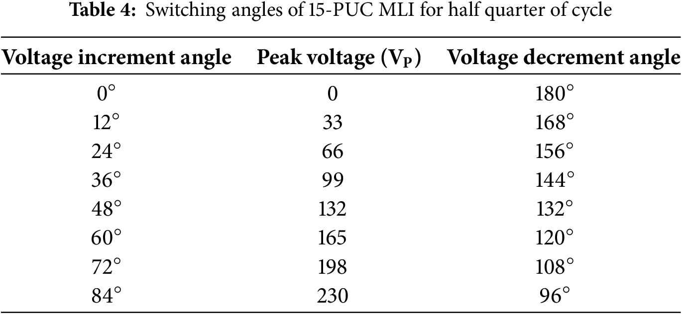
Following Fig. 14 consists of a half quarter predetermined switching angle voltage stepped waveform. The stepped waveform consists of both even and odd harmonics, but even harmonics are not considerable to effect the system. The advanced level shift PWM is eliminate zero and third order harmonics, we consider to control odd order harmonics only.

Figure 14: 15 level steeped waveform with half quarter switch angles
The Fourier series representation of the 15-level fundamental stepped voltage waveform is expressed as follows.
The novel switching algorithm is influence to 15-PUC outputs predictively. Through that comparison of sin & carrier waveforms, required unique switching pulses of 15-PUC MLI is shown in Fig. 15. Blue colour switching pulses
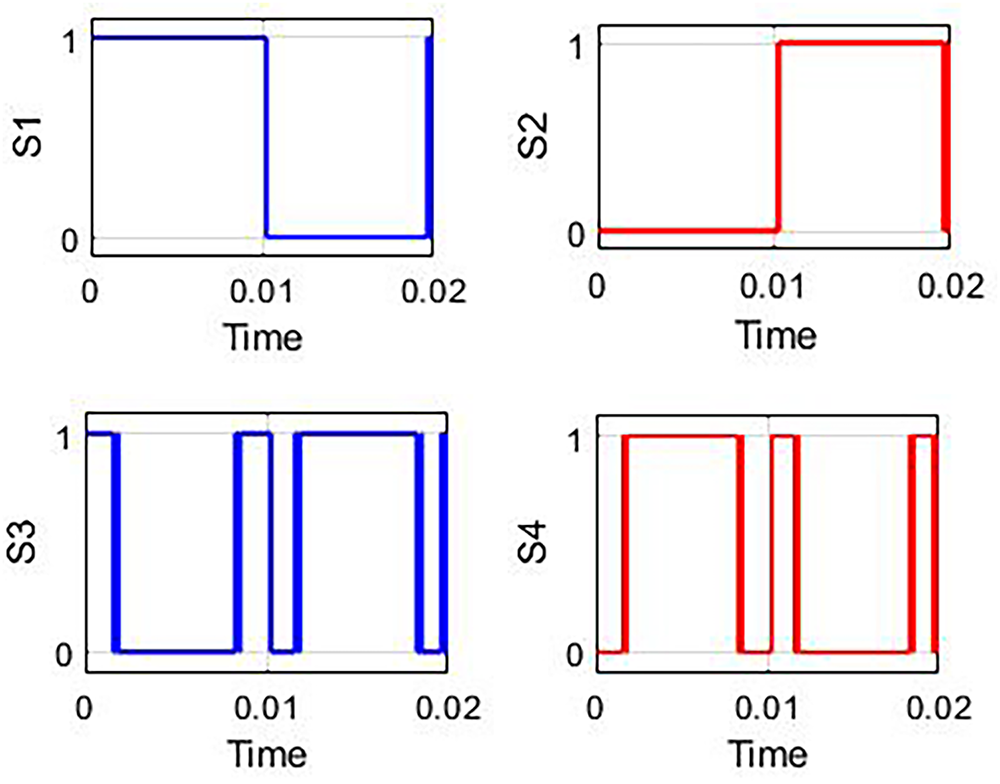
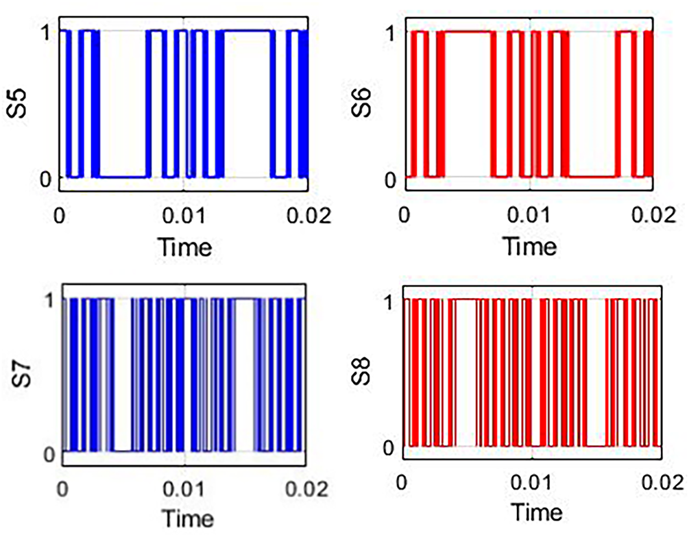
Figure 15: Required switching pulses of 15-PUC MLI peak voltage
Every half cycle consists of 15 time periods only
Following Table 4 consists of voltage increment and decrement angles for half quarter cycle.
4 Sensor-Less PR Voltage Controller Integrated into PWM & Switching Algorithm
15-level PWM contains, sinusoidal reference waveform with fourteen carriers is already discussed in above. The sin reference (
According to previous research, conventional linear controllers encounter significant challenges in accurately sensing and responding to abrupt changes in load and source parameters, as well as in maintaining stable capacitor voltages. To overcome these limitations, this work introduces a sensorless Proportional Resonant (PR) controller specifically designed for the 15-level Packed U Cell (15-PUC) multilevel inverter. Fig. 16 provides a schematic representation of the sensorless voltage controller integrated within the 15-PUC system.

Figure 16: Sensor less controller for 15-PUC systems
The sensorless PR controller for the inverter system regulates the output voltage without relying on physical sensors. It utilizes a combination of a Proportional Resonant (PR) controller, a Phase-Locked Loop (PLL), and a PWM-based switching algorithm. The PR controller receives the reference voltage Vref and compares it with the actual output to generate an error signal. This error is processed using the PR control law, which is specifically designed to eliminate steady-state error for sinusoidal signals. The transfer function of the PR controller is given by:
where Kp is the proportional gain, Ki is the resonant gain, and ω0 = 2πf0 is the resonant frequency corresponding to the grid or desired output frequency. This structure enables the controller to provide high gain at the resonant frequency, ensuring accurate tracking of sinusoidal references. The PLL (Phase-Locked Loop) ensures synchronization with the grid or reference signal, while the PWM (Pulse Width Modulation) algorithm converts the control signal into switching pulses for the inverter switches (S1 to S8). Together, these components facilitate precise voltage control and waveform shaping, even in the absence of direct current or voltage sensors—making the system more robust and cost-effective for practical applications.
The PR controller is designed to track sinusoidal reference signals with zero steady-state error, making it ideal for AC systems like inverters. Unlike a traditional PI controller, which struggles with AC signals, the PR controller introduces a resonant term that provides infinite gain at a specific frequency (usually the grid frequency). The PR controller predominantly controls the amplitude, described phase shifting signals are fetched from load. Measured voltage angle from the grid is injected PLL block for extracting the angle. PLL block supports to control switching & grid frequencies, and it provides proper phase shift with the help of sin block combination. The maximum value of reference current
The 15-PUC is realized in MATLAB/Simulink environment for the proposed PR controller. The controller balances the capacitor voltages automatically, and the performance is evaluated for standalone applications. The Load parameters of 15-PUC MLI are presented in Table 5.

Fig. 17a,b represents the 15 level load voltage and load current output waveforms of 15-PUC MLI for R load. By using advanced sensor less PR controller the load voltage & current harmonic Figures represent at Fig. 17c,d (9.48% & 3.87%), by which it eliminates the bulky harmonic design of filter circuits. The Fast Fourier Transform (FFT) analysis proves that load current THD is falling under universal IEEE standard 519.

Figure 17: (a–d) Output waveforms for 15-PUC MLI using standalone mode for R load
The load values of RL are R1 & L1: 40 Ω & 300 mH, respectively. Fig. 18a,b represents the 15-level load voltage and load current output waveforms of 15-PUC MLI. By using advanced sensor less PR controller the load voltage & current harmonics are found to be less than 5% (i.e., 3.70% & 1.09%) by which it eliminates zero and third order harmonics effectively. The voltage current harmonics are represented at Fig. 18c,d. The Fast Fourier Transform (FFT) analysis proves that THD is falling under universal IEEE standard 519.

Figure 18: (a–d) Output waveforms for 15-PUC MLI using standalone mode for RL load
The performance of the 15-level PUC MLI is evaluated under varying source regulations within the interval of 0 to 0.04 ms, with a step change in load conditions illustrated in Fig. 19. The results indicate that the voltage and current waveforms achieve stabilization at approximately 0.05 ms, with a settling time of just 0.01 ms. For this analysis, resistive and inductive load values are set at 40, 100 Ω, and 300, 200 mH, respectively. The highlighted sections in the figures provide detailed views of the inverter’s dynamic response under different loading scenarios.

Figure 19: Step change in input voltage
Figs. 19 and 20 further demonstrate the electrical system’s behavior following a sudden increase in input voltage—from 200 V to 230 V at around 0.045 s, as shown in Fig. 19. The corresponding output voltage initially exhibits transient oscillations, eventually stabilizing into a steady sinusoidal waveform between −250 V and +250 V. This dynamic-to-steady-state transition showcases the robust response and stability of the system. Fig. 20a clearly depicts the output response, effectively capturing both transient phases (emphasized by the dotted oval) and the subsequent sustained sinusoidal operation. This ability to quickly recover and maintain regular oscillation after a disturbance is a strong indicator of robust system design and reliable performance in electrical engineering applications.
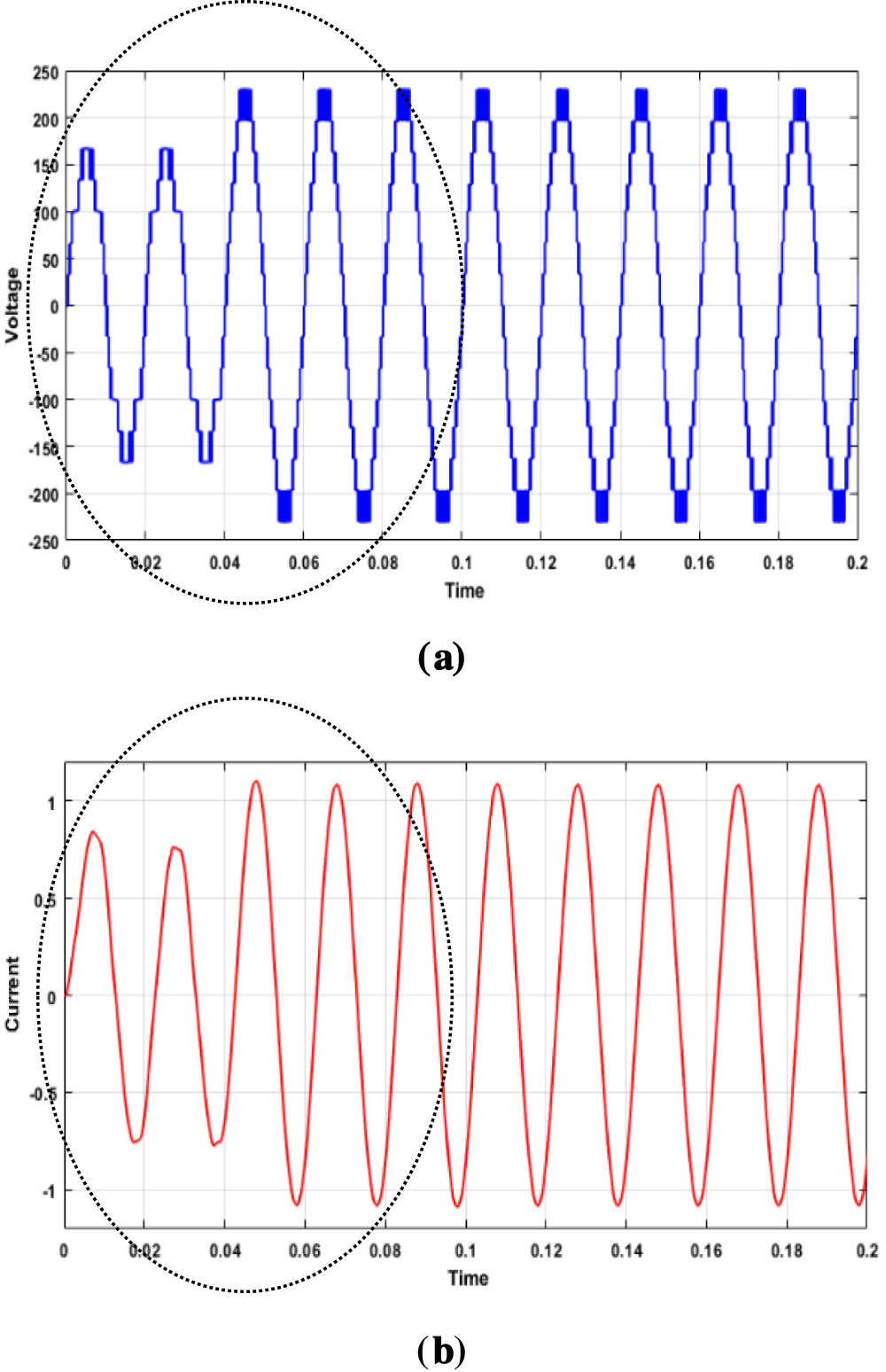
Figure 20: (a,b) Dynamic behavior of 15-PUC MLI
Fig. 20b presents the alternating current (AC) waveform over a time interval of 0 to 0.2 s. The red sinusoidal trace smoothly oscillates between −1 and +1 units, demonstrating a stable and symmetric AC signal. This regular and distortion-free pattern is characteristic of properly functioning electrical systems and highlights the inherent periodicity of AC current flow. The observed consistency in amplitude and symmetry indicates that the system operates without transient disruptions, serving as an exemplary depiction of ideal AC current behavior in practical electrical circuits.
Experimental: The practical implementation of the proposed sensorless controller for the 15-level Packed U-Cell (PUC) inverter system presents several challenges. First, achieving accurate current and voltage control without physical sensors demands highly reliable estimation algorithms, which can be sensitive to noise, temperature variations, and component tolerances. Second, the integration of advanced control blocks like the PR controller and Phase-Locked Loop (PLL) requires precise tuning to maintain synchronization and stability, especially under dynamic load conditions. Third, the real-time execution of the switching algorithm and PWM generation necessitates high-speed digital signal processing hardware, which can increase system complexity and cost. Additionally, ensuring consistent capacitor voltage balancing and managing switching losses across multiple levels further complicates the design and implementation process. We can close this gap in the future.
In this work, a sensorless PR controller-based 15-level Packed U Cell (15-PUC) multilevel inverter has been developed and realized. A novel switching algorithm was designed and implemented to optimize the inverter operation. The proposed PR controller integrated with an advanced level-shift PD-PWM technique effectively reduces switching stress while enhancing transient response. This controller actively compensates for DC-link capacitor voltage without needing feedback from the source or load, thereby eliminating the requirement for voltage sensors. Simulation results for resistive (R) and resistive-inductive (RL) load cases demonstrate that the total harmonic distortion (THD) remains within the IEEE-519 standard limits. The proposed approach also shows robust performance under dynamic load changes, with DC voltage variations from 200 V to 230 V. Overall, the 15-PUC inverter topology combined with the sensorless PR controller is highly suitable for renewable energy and grid-connected applications.
Acknowledgement: Authors used Perplexity AI for English language polishing.
Funding Statement: The authors received no specific funding for this study.
Author Contributions: Conceptualization, K. Naga Venkata Siva, Damodhar Reddy, and P. Krishna Murthy; methodology, Kiran Kumar Pulamolu, M. Dharani, and T. Venkatakrishnamoorthy; validation, K. Naga Venkata Siva, Damodhar Reddy, and P. Krishna Murthy; formal analysis, Kiran Kumar Pulamolu, M. Dharani, and T. Venkatakrishnamoorthy; investigation M. Dharani, and T. Venkatakrishnamoorthy; Writing—original draft, Kiran Kumar Pulamolu, Damodhar Reddy, and P. Krishna Murthy; Writing—review & editing, K. Naga Venkata Siva; supervision, T. Venkatakrishnamoorthy. All authors reviewed the results and approved the final version of the manuscript.
Availability of Data and Materials: Not applicable.
Ethics Approval: Not applicable.
Conflicts of Interest: The authors declare no conflicts of interest to report regarding the present study.
Nomenclature
| PUC | Packed U cell |
| VC1 | Dc link Capacitor 1 |
| VC2 | Dc link Capacitor 2 |
| SL | Sensor less |
| PRC | Proportional Resonant Controller |
| TCB | Triangular Carrier Based |
| LS | Level shift |
| L | Inductor Value |
| R | Resistor Value |
| MLI | Multilevel Inverter |
| SPWM | Sinusoidal Pulse Width Modulation |
| THD | Total Harmonic Distortion |
| MI | Modulation Index |
| PLL | Phase Locked Loop |
| Number of Carriers | |
| Number of Levels |
References
1. Subramanian N, Stonier AA. Quantitative analysis of reliability and cost function of 15-level inverter. IEEE Access. 2025;13:171889–901. doi:10.1109/access.2025.3616252. [Google Scholar] [CrossRef]
2. Vijeh M, Rezanejad M, Samadaei E, Bertilsson K. A general review of multilevel inverters based on main submodules: structural point of view. IEEE Trans Power Electron. 2019;34(10):9479–502. doi:10.1109/tpel.2018.2890649. [Google Scholar] [CrossRef]
3. Lin Z, Zhang X, Zhu J, Du W, Ye J, Bai Y. Advances in space vector modulation techniques for multilevel inverters: a comprehensive review. Chin J Electr Eng. 2025;11(2):63–77. doi:10.23919/cjee.2025.000146. [Google Scholar] [CrossRef]
4. Ni J, Wang C, Sun S, Sun Y, Ma G. Fault diagnosis method for photovoltaic grid-connected inverters based on MPA-VMD-PSO BiLSTM. Energy Eng. 2025;122(9):3719–36. doi:10.32604/ee.2025.066971. [Google Scholar] [CrossRef]
5. Vahedi H. 5-level packed U-cell (PUC5) active front-end rectifier. IEEE Open J Power Electron. 2025;6:1022–7. doi:10.1109/ojpel.2025.3576301. [Google Scholar] [CrossRef]
6. Kumar JSVS, Mustafa M, Begum SMU, Suresh B, Narasipuram RP. A digital twin-driven IoT architecture for enhanced xEV performance monitoring. Energy Eng. 2025;122:1–10. doi:10.32604/ee.2025.070052. [Google Scholar] [CrossRef]
7. Nalavala RR, Suneetha B, Suresh B, Pasha MM. Advanced control strategies for modelling and optimisation of hybrid microgrid for xEV applications. Int J Math Model Numer Optim. 2026;1(1):10073026. doi:10.1504/ijmmno.2026.10073026. [Google Scholar] [CrossRef]
8. Muthukuri NK, Mopidevi S. Analysis of a modified switching pattern for packed U cell-15 inverter topology with advanced level shift carrier pulse width modulation techniques. Electrica. 2021;21(2):272–82. doi:10.5152/electrica.2021.20082. [Google Scholar] [CrossRef]
9. Muthukuri NK, Narsipuram RP, Mopidevi S. Optimization of total harmonic distortion using carrier based PWM techniques for nested multilevel inverter topologies. Int J Ind Electron Drives. 2020;5(2):85–100. doi:10.1504/ijied.2020.10038324. [Google Scholar] [CrossRef]
10. Rajanand Patnaik N, Tagore YR, Chaitanya S. Advanced seven level transformer-less multilevel inverter topology for PV application. In: Proceedings of the 2017 Third International Conference on Advances in Electrical, Electronics, Information, Communication and Bio-Informatics (AEEICB); 2017 Feb 27–28; Chennai, India. New York, NY, USA: IEEE; 2017. doi:10.1109/aeeicb.2017.7972393. [Google Scholar] [CrossRef]
11. Rajanand Patnaik N, Ravindranath Tagore Y. Design and evaluation of PUC (Packed U Cell) topology at different levels & loads in terms of THD. Eur J Adv Eng Technol. 2016;3(9):33–43. [Google Scholar]
12. Narasipuram RP. Optimal design and analysis of hybrid photovoltaic-fuel cell power generation system for an advanced converter technologies. Int J Math Model Numer Optim. 2018;8(3):245. doi:10.1504/ijmmno.2018.088990. [Google Scholar] [CrossRef]
13. Li H, Liu C, Jiang X, Zeng Y, Guo Z, Zheng TQ. A time-domain stability analysis method for grid-connected inverter with PR control based on floquet theory. IEEE Trans Ind Electron. 2021;68(11):11125–34. doi:10.1109/tie.2020.3036227. [Google Scholar] [CrossRef]
14. Roy T, Tesfay MW, Nayak B, Panigrahi CK. A 7-level switched capacitor multilevel inverter with reduced switches and voltage stresses. IEEE Trans Circuits Syst II. 2021;68(12):3587–91. doi:10.1109/tcsii.2021.3078903. [Google Scholar] [CrossRef]
15. Pal S, Ghosh Majumder M, Resalayyan R, Gopakumar K, Umanand L, Malinowski M, et al. A ten-level inverter fed drive scheme with extended linear modulation range. IEEE Trans Ind Electron. 2022;69(12):12261–9. doi:10.1109/tie.2021.3134055. [Google Scholar] [CrossRef]
16. Rakesh R, Ramachandran KR, Yadav AK, Gopakumar K, Umanand L, Matsuse K. A switched capacitive filter-based harmonic elimination technique by generating a 30-sided voltage space vector structure for IM drive. IEEE Trans Power Electron. 2020;35(3):2402–10. doi:10.1109/tpel.2019.2930280. [Google Scholar] [CrossRef]
17. Pal S, Majumder MG, Rakesh R, Gopakumar K, Umanand L, Zielinski D, et al. A cascaded nine-level inverter topology with T-type and H-bridge with increased DC-bus utilization. IEEE Trans Power Electron. 2021;36(1):285–94. doi:10.1109/tpel.2020.3002918. [Google Scholar] [CrossRef]
18. Guo F, Yang T, Diab AM, Yeoh SS, Li C, Bozhko S, et al. An overmodulation algorithm with neutral-point voltage balancing for three-level converters in high-speed aerospace drives. IEEE Trans Power Electron. 2021;37(2):2021–32. doi:10.1109/tpel.2021.3105752. [Google Scholar] [CrossRef]
19. Majumdar S, Mahato B, Jana KC. Implementation of an optimum reduced components multicell multilevel inverter (MC-MLI) for lower standing voltage. IEEE Trans Ind Electron. 2020;67(4):2765–75. doi:10.1109/tie.2019.2913812. [Google Scholar] [CrossRef]
20. Muthukuri NK. Hardware implementation of modular hybrid power generation system architecture with sensor less controller for battery storage applications. Int J Math Model Numer Optim. Forthcoming. 2026. doi:10.1504/IJMMNO.2026.10072336. [Google Scholar] [CrossRef]
21. Narasipuram RP, Yadlapalli RT. Performance analysis and design optimisation of 3-Ø Packed U Cell inverter for industrial drive applications. Int J Math Model Numer Optim. 2019;9(3):309. doi:10.1504/ijmmno.2019.100518. [Google Scholar] [CrossRef]
22. Chaitanya S, Patnaik NR, Murthy KVSR. A novel seven level symmetrical multilevel inverter topology. In: Proceedings of the 2017 Third International Conference on Advances in Electrical, Electronics, Information, Communication and Bio-Informatics (AEEICB); 2017 Feb 27–28; Chennai, India. New York, NY, USA: IEEE; 2017. doi:10.1109/aeeicb.2017.7972347. [Google Scholar] [CrossRef]
23. Bana PR, Panda KP, Padmanaban S, Mihet-Popa L, Panda G, Wu J. Closed-loop control and performance evaluation of reduced part count multilevel inverter interfacing grid-connected PV system. IEEE Access. 2020;8:75691–701. doi:10.1109/access.2020.2987620. [Google Scholar] [CrossRef]
24. Siddique MD, Mekhilef S, Shah NM, Sarwar A, Iqbal A, Memon MA. A new multilevel inverter topology with reduce switch count. IEEE Access. 2019;7:58584–94. doi:10.1109/access.2019.2914430. [Google Scholar] [CrossRef]
25. Gupta KK, Jain S. Topology for multilevel inverters to attain maximum number of levels from given DC sources. IET Power Electron. 2012;5(4):435–46. doi:10.1049/iet-pel.2011.0178. [Google Scholar] [CrossRef]
26. Alishah RS, Nazarpour D, Hosseini SH, Sabahi M. New hybrid structure for multilevel inverter with fewer number of components for high-voltage levels. IET Power Electron. 2014;7(1):96–104. doi:10.1049/iet-pel.2013.0156. [Google Scholar] [CrossRef]
27. Dhanamjayulu C, Khasim SR, Padmanaban S, Arunkumar G, Holm-Nielsen JB, Blaabjerg F. Design and implementation of multilevel inverters for fuel cell energy conversion system. IEEE Access. 2020;8:183690–707. doi:10.1109/access.2020.3029153. [Google Scholar] [CrossRef]
28. Mohamad AS. Matrix inverter: a multilevel inverter based on matrix converter switch matrix. In: Proceedings of the 2020 IEEE Electric Power and Energy Conference (EPEC); 2020 Nov 9–10; Edmonton, AB, Canada. New York, NY, USA: IEEE; 2020. doi:10.1109/epec48502.2020.9320121. [Google Scholar] [CrossRef]
29. Mahato B, Majumdar S, Vatsyayan S, Jana KC. A new and generalized structure of MLI topology with half-bridge cell with minimum number of power electronic devices. IETE Tech Rev. 2021;38(2):267–78. doi:10.1080/02564602.2020.1726215. [Google Scholar] [CrossRef]
30. Dhanamjayulu C, Meikandasivam S. Implementation and comparison of symmetric and asymmetric multilevel inverters for dynamic loads. IEEE Access. 2018;6:738–46. doi:10.1109/access.2017.2775203. [Google Scholar] [CrossRef]
31. Sarwer Z, Siddique MD, Iqbal A, Sarwar A, Mekhilef S. An improved asymmetrical multilevel inverter topology with reduced semiconductor device count. Int Trans Electr Energ Syst. 2020;30(11):e12587. doi:10.1002/2050-7038.12587. [Google Scholar] [CrossRef]
32. Nisha G, Jamuna K. Real-time implementation of sliding mode controller for standalone microgrid systems for voltage and frequency stabilization. Energy Rep. 2023;10(3):768–92. doi:10.1016/j.egyr.2023.07.015. [Google Scholar] [CrossRef]
33. Zhu B, Chen X, Luo X. VSC control strategy for HVDC compensating harmonic components. Energy Rep. 2023;9(4):1101–7. doi:10.1016/j.egyr.2023.06.055. [Google Scholar] [CrossRef]
34. Dhanamjayulu C, Sanjeevikumar P, Muyeen SM. A structural overview on transformer and transformer-less multi level inverters for renewable energy applications. Energy Rep. 2022;8(8):10299–333. doi:10.1016/j.egyr.2022.07.166. [Google Scholar] [CrossRef]
Cite This Article
 Copyright © 2026 The Author(s). Published by Tech Science Press.
This work is licensed under a Creative Commons Attribution 4.0 International License , which permits unrestricted use, distribution, and reproduction in any medium, provided the original work is properly cited.
 Downloads
 Citation Tools