
 Submit a Paper
 Propose a Special lssue
 Open Access
ARTICLE
Enhanced Thermal Performance of a Shell and Coil Tube Heat Exchanger Using Fins and Slots
1 Building and Construction Department, Shaqlawa Technical College, Erbil Polytechnic University, Erbil, 44001, Iraq
2 Department of Mechanical and Energy Engineering, Erbil Technical Engineering College, Erbil Polytechnic University, Erbil, 44001, Iraq
* Corresponding Author: Najiba Hasan Hamad. Email:
(This article belongs to the Special Issue: Advancements in Energy Resources and Their Processes, Systems, Materials and Policies for Affordable Energy Sustainability)
Energy Engineering 2026, 123(1), 14 https://doi.org/10.32604/ee.2025.073377
Received 17 September 2025; Accepted 13 November 2025; Issue published 27 December 2025
 View Full Text
 Download PDF
Abstract
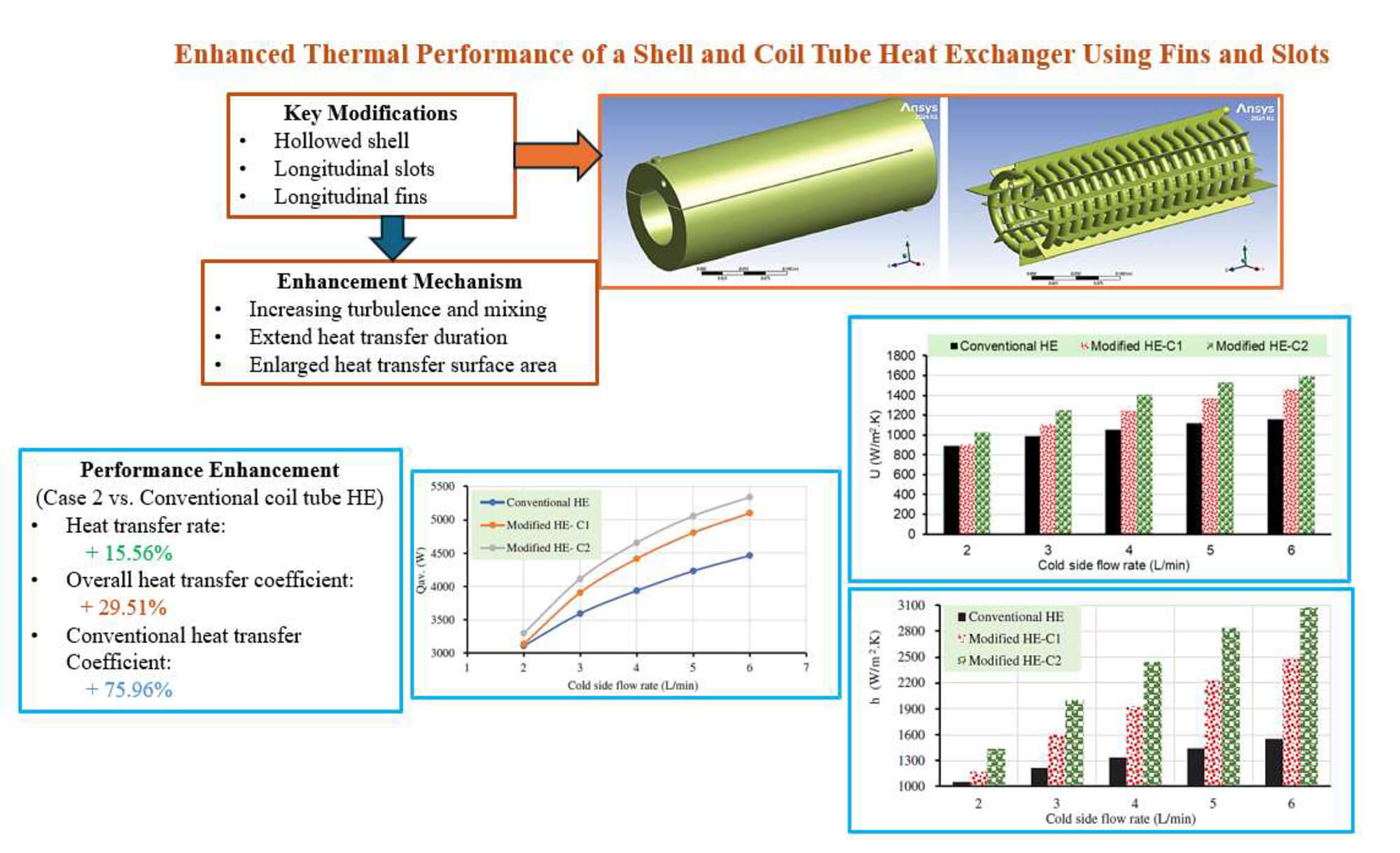
Coiled tube heat exchangers are widely preferred in shell structures due to their superior heat transfer performance, driven by favorable flow characteristics. This study investigates the effect of modifying coil and shell configurations on heat transfer efficiency. Two key enhancements were examined: adding fins to the outer coil surface and integrating longitudinal slots within a hollowed shell. These modifications promote turbulence and extend heat transfer duration, thereby improving performance. However, they also introduce challenges, including increased pressure loss and manufacturing complexity. Numerical simulations were conducted using ANSYS Fluent 2024R1 under identical boundary conditions. With a fixed cold-side flow rate of 3 L/min, the input temperatures for the hot and cold fluids were 333.15 and 291.65 K, respectively. The hot-side flow rate varied between 2 and 6 L/min. Simulation outcomes were reported for the objectives of the study that included the improvement in heat exchangers’ heat transfer enhancement. As it was indicated in the study outcomes, the average heat transfer rate increased by 15.56%, the overall heat transfer coefficient enhanced by about 29.51%, and the convective heat transfer coefficient improved by about 75.96% compared to the conventional shell-and-coil tube heat exchanger model. However, the modified technique resulted in a significant pressure drop.Graphic Abstract
Keywords
Heat exchangers are essential elements in thermal operation systems in a broad range of industries, such as power generation, HVAC, petrochemicals, and chemicals. One of the core objectives in the design of these systems is the effective transmission of heat between two or more fluids with a minimum amount of energy loss [1,2].
In recent decades, more advanced heat exchanger configurations, such as the shell-and-coil heat exchanger (S-CHE), have been explored due to their superior thermal performance, especially in situations where space constraints are a critical concern, besides the efficiency augmentation. When compared to conventional straight-tube heat exchangers, the coil tube heat exchangers have demonstrated superior heat transfer properties. The coil’s inherent curvature promotes centrifugal forces, which lower the thermal boundary layer and increase fluid turbulence. Therefore, these devices may exhibit a comparatively smaller footprint while achieving greater heat transfer coefficients [3,4].
Secondary flow, or Dean vortices, is created by coils, increasing turbulence and enhancing thermal performance. However, for more optimization, modifications to the layout are required due to limitations such as fouling, pressure drop, and uneven temperature distribution, which were investigated [5,6]. To overcome these obstacles, recent research has concentrated on surface modifications, geometric changes, and hybrid approaches [7–9]. Additionally, various active and passive techniques have been developed to improve heat transfer performance while concurrently lowering pressure losses in light of recent developments in coiled tube research. The majority of S-CTHE research focuses on passive enhancement techniques, which do not require any external energy input. It has been observed that alterations in coil shape, such as changes in diameter and pitch, improve the impact of secondary flow. For instance, under turbulent flow conditions, investigations have demonstrated that the coil pitch had a major impact on both the friction factor and the properties of heat transmission. Coils were used with coil pitch values of 20, 35, and 50 mm [10]. In addition, coiled tubes with five annular cross-section shapes—square, rectangular, triangular, elliptical, and circular—were examined numerically at Reynolds numbers ranging from 4700 to 26,700. The outcomes reported that the circular shape outperformed the elliptical, square, rectangular, and triangular designs in terms of heat transfer enhancement by 4%, 14.6%, 17.8%, and 30.1%, respectively [11]. A review of studies investigating the heat transfer and flow characteristics of spiral tube heat exchangers, as experienced by many authors [5,12–14], revealed that the addition of fins indicated a significant impact on the performance of modified shell-and-coil tube heat exchangers, compared to other enhancement techniques, like coiled wire inserts [15–17], dimples [18–20], twisted tape [21–24], corrugation of the straight tube [25–30], and coil shell layout modifications [31].
Although finned heat exchangers are frequently employed to improve heat transfer, little is known about how the number of fins affects the thermal-hydraulic performance of spiral tube heat exchangers. Researchers have applied a unique method to enhance the efficiency of coil heat exchangers by integrating rings as baffles [32]. In a similar attempt, the authors investigated how three structural factors affected the shell and spiral tube heat exchanger’s thermal efficiency by replacing the base shape of the spiral tube with a novel serrated spiral tube and adding baffles inside the shell domain. The main conclusions of the study show that, in comparison to a standard helical tube heat exchanger, a serrated helical tube offers a performance improvement of about 30%. On the other hand, the serrated helical tube’s U factor is 34% higher than that of the baffled helical tube heat exchanger and 70% higher than that of the conventional [33].
In an experimental work, the spiral fins’ impact was examined. According to the findings, the heat transmission factor and overall performance had increased by 14.19% and 38.79%, respectively [34]. Subsequently, in an experimental and numerical study, a novel type of shell-and-coiled tube heat exchanger was investigated. The results of an experimental and numerical study have led to the development of a better, more affordable, and more readily adaptable design for increasing the heat exchange rate in a shell and helically coiled heat exchanger [35].
To meet the growing demands for improved heat transfer processes and energy efficiency, it is imperative to investigate novel shell-and-coil tube heat exchanger designs. Therefore, the objective of the present study is to identify an optimized method that enhances the conventional shell-and-coil tube heat exchanger’s thermal performance. This effort involved improving the heat transfer rate and both essential coefficients of convection heat transfer and overall heat transfer. The current study focused on an optimized technique that improved the thermal performance of the conventional coil heat exchanger, including improvement in the heat transfer rate and both the crucial coefficients of convection heat transfer and overall heat transfer with an acceptable pressure loss.
2 Computational Modeling and Simulation
The computational fluid dynamics (CFD) method is employed to simulate the fluid flow and thermal properties in a coil tube using commercial software, ANSYS Fluent (2024 R1). A horizontal orientation and an internal coiled tube are features of the heat exchangers examined in the current work. Liquid water enters the shell from the lower port, departs from the upper port, and circulates within the coiled tube as presented in Fig. 1. The model design was enhanced with the same dimensional values of the conventional shell-and-coil tube heat exchanger with two different modifications, expressed as case 1 (C1) and case 2 (C2). The first modified model, which is C1, represented an integration of four longitudinal slots with dimensions of 305 mm length, 32.5 mm width, and 1.5 mm thickness along a hollowed shell (the hollowed diameter is 75 mm), as shown in Fig. 2. For the second modified model, C2, as illustrated in Fig. 3, along with the changes made in the first model (C1), eight longitudinal fins were added to the coil’s surface to increase the area for heat transfer. Knowing that the fins are 300 mm long, 28 mm wide, and 1 mm thick.

Figure 1: Conventional shell-and coil tube heat exchanger geometry with smooth coiled tube
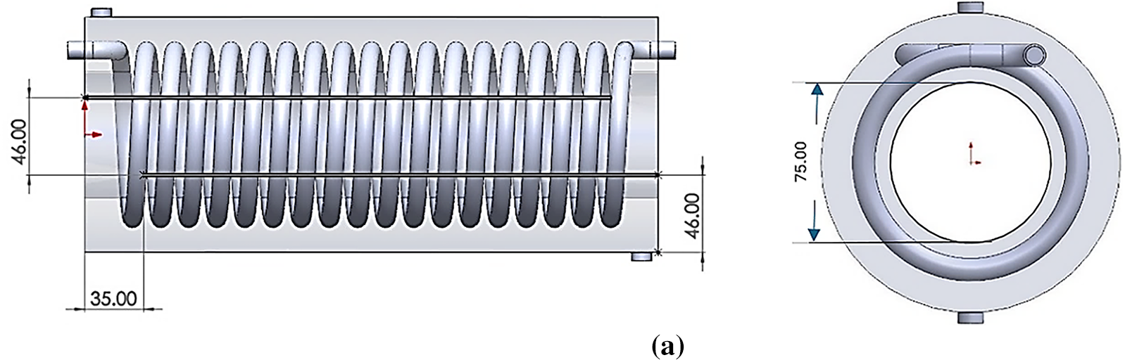
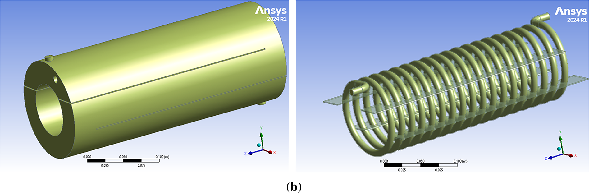
Figure 2: Modified shell-and-coil tube geometry, Case-2, consisted of: (a) Hollowed shell; (b) Four longitudinal slots inside the shell
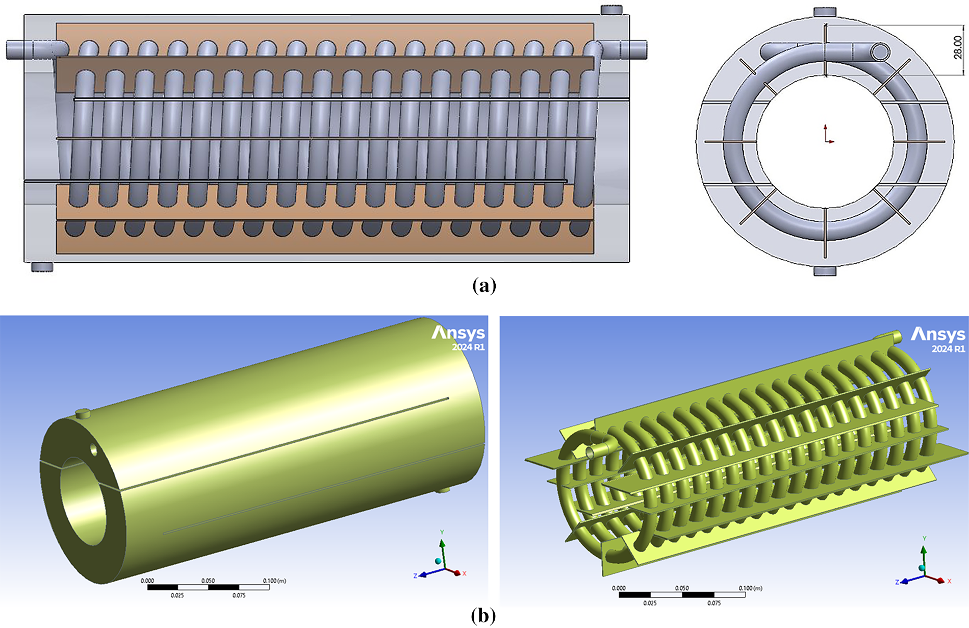
Figure 3: Modified shell-and-coil tube geometry, case-2, consisted of: (a) Hollowed shell; (b) Four longitudinal slots inside the shell and eight longitudinal fins along the coil
This study attempts to evaluate the new design’s potential for improvement; hence, all geometric parameter values were kept constant for both the conventional and modified designs to make a fair comparison possible. For estimating the general parameters’ dimensions, an experimental study was utilized [32]. The mutual geometric parameters are illustrated in Table 1.

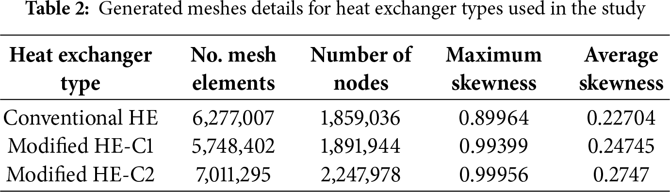
A system’s performance under various operational and design conditions could be simulated using CFD technique. The CFD method is frequently applied in engineering applications, combining various energy systems, and is a potent device for comprehending and gathering a system’s reaction. For computational fluid dynamics investigations, a suitable mesh structure must be defined. This study of conventional and modified shell and coil tube models was meshed using the ANSYS Mesh Module, as it was presented in Fig. 4a–c. Generated mesh details for conventional and both models of modified heat exchangers used in the present study are represented in Table 2.
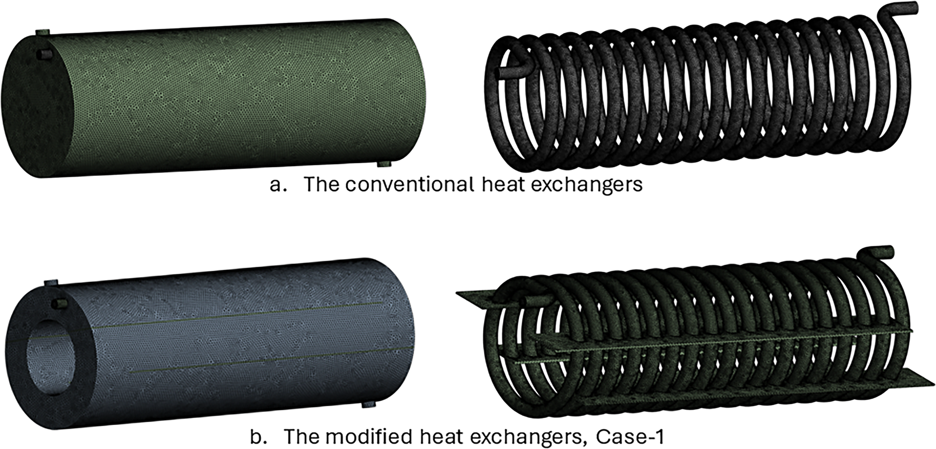
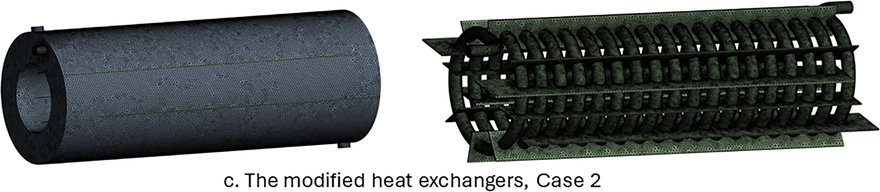
Figure 4: The details of the generated meshes of the simulated shell-and-coil tube heat exchangers: (a) the conventional heat exchanger; (b) the modified heat exchanger, Case-1; (c) the modified heat exchanger, Case-2
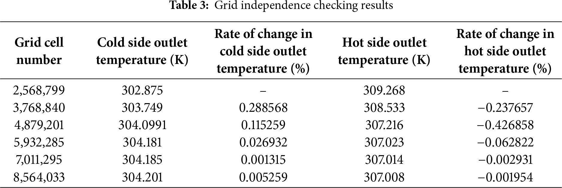
In numerical solutions, the grid independence method is essential. Although a finer mesh improves solution accuracy, it also extends solution time, which may be a drawback. The grid independence approach illustrated in Table 3 has been used to produce an ideal mesh. According to the illustrated figures, with mesh number 5,932,285 forward, the fluctuations in cold side and hot side fluid outlet temperatures become linear and stay almost constant. This pattern continues until mesh number 8,564,033, at which point mesh number 5,932,285 was chosen to be the most effective mesh.
2.3 CFD Evaluation and Governing Equations
The CFD methodology is an effective way to assess a system’s behavior in a way that is close to reality. This technique reduces the time and effort required to identify a system’s result under various operating conditions. Important details regarding the thermal and flow characteristics of a system can be derived by repeatedly analyzing it under different conditions. Once the simulation results are obtained, the system can be fabricated to the required specifications.
To evaluate the effect of integrating longitudinal slots along the hollowed shell and fin application, CFD simulations were performed in this regard. The following are the necessary governing formulas for CFD analysis, which have been recommended in various studies [36–38].
Continuity equation:
Momentum equation:
Energy equation:
The flow field of this kind of complicated heat exchanger is predicted to exhibit turbulent flow inside the shell and coil tube heat exchanger based on the initial numerical analysis. The k provides an appropriate approach to turbulence phenomena inside the flow field—∈ model of turbulence, as it is widely used for various energy systems, such as heat exchangers [39,40]. In this case, the CFD analysis step of the current study used the k-∈ turbulence model, which might be provided using the illustrated formulas, where ∈ indicates the rate of kinetic energy dissipation and k represents turbulent kinetic energy.
In the above equations, Eb indicates the turbulence kinetic energy generation resulting from the buoyancy effect. In contrast, Ek indicates the turbulence kinetic energy generation resulting from the difference in velocity, Qk, and Q∈ denote the sources. Ef signifies the effect of fluctuating strains in compressible turbulence upon global dissipation, while A1∈, A2∈, and A3∈ are constant values, which are illustrated as: A1∈ = 1.44, A2∈ = 1.0, and A3∈ = 1.92.
Furthermore, δ∈ and δk represent the Prandtl numbers for ∈ and k, respectively. The values of δ∈ and δk are illustrated as 1.3 and 1, respectively.
Thus, the turbulent viscosity, μt, may be reported through ∈ and k in the earlier equations to give:
Eq. (7) for the turbulence intensity is adopted from [41], as:
where Re indicates the Reynolds number of the flow.
During the material selection step of the modeling analysis, copper was adopted for the coil section located inside the shell. Moreover, stainless steel was selected for the shell side of the SCHEs. For both sides of the modified and conventional models, liquid water was chosen as the working fluid. The entrance temperatures for the coil side and shell side were determined to be 333.15 and 291.65 K, respectively, in the initial stage of the CFD study. The cold side flow rates of 2 to 6 L/min have been used in simulations.
On the hot side, a flow rate of 3 L/min was kept constant. The examination of such a type of heat exchanger in the simulation portion of the current work was conducted under a steady-state setting. The coupled approach was chosen to be employed for coupling pressure-velocity in order to replicate the model. When calculating the momentum and energy equations in the numerical analysis, second-order upwind was chosen. Furthermore, when modeling the traditional and modified coil heat exchanger, convergence criteria for continuity, energy, and velocity were preferred as 10−5, 10−7, and 10−5, respectively.
The following assumptions were considered as operational conditions:
• A three-dimensional model.
• The fluid is still incompressible, single-phase, and steady-state.
• This analysis ignores heat transmission, radiation, and gravity.
• A fluid’s characteristics change with temperature.
Additional computations are needed to translate the outcomes of CFD simulations into useful data to compare the heat exchangers’ performances. The following formulas and simplifications are frequently used in the literature in the computations performed in these kinds of investigations by Gomaa et al. [41] and Alikhan et al. [42]. By using Eqs. (8) and (9) to compute the amount of heat transmitted from each fluid, Eq. (10) was used to get the average heat transfer rate. The average specific heat capacity (Cp) over the relevant temperature variation is used in these computations.
An essential metric for assessing the thermal effectiveness of a heat exchanger is the overall heat transfer coefficient (U), which is determined by Eq. (11).
In Eq. (11), ΔTLMTD represents the Logarithmic Mean Temperature Difference, and A is the contact region’s surface area where heat transfer occurs. To achieve ΔTLMTD, take the actions listed in Eqs. (12)–(14):
3.1 Validation of the Computational Procedure
In this section, with the same material properties, boundary conditions, and thermophysical properties and assumptions as were reported by Güngör et al. [32], with the same operational conditions and same material properties, the results achieved in the present work were provided and compared with the results of the conventional model, for both tube outlet temperature and shell outlet temperature. As shown in Fig. 5, the validation results indicated an acceptable agreement.
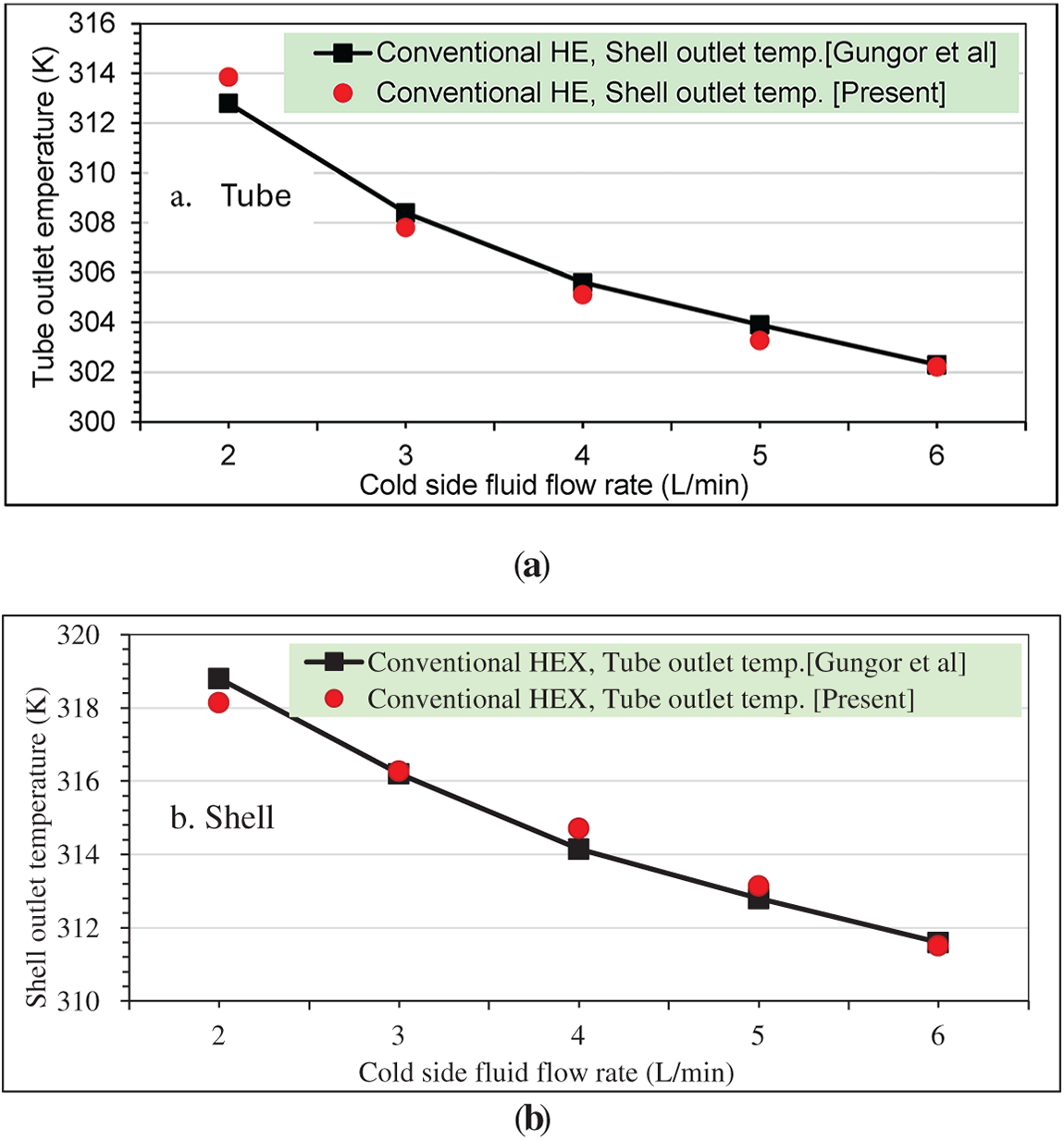
Figure 5: Comparison of the present study results with Güngör et al. [32] results: (a) tube outlet temperature; (b) shell outlet temperature
3.2 Analysis of the Numerical Results
With the two designs mentioned above, the simulations were run using ANSYS Fluent. The simulations were carried out under the assumption of steady-state circumstances, using the k-∈ turbulence model. It was indicated that hot fluid enters the tube side and cold fluid enters the shell side. For both sides, water was selected as the fluid; the Fluent database was used to select its characteristics.
A fluid particle’s streamline is its path through the field of the flow. It provides an overview of the flow structure and is frequently utilized to calculate the effectiveness of novel fluid flow models. The conventional and modified SCHE streamlines are displayed in Fig. 6a–c. As can be observed from the modified shell and coil heat exchangers’ streamlines, both modified models of C1 and C2 constrain the particles of the fluid to follow a predetermined path with detours around the coiled tube. More fluid particles come into contact with the coiled tube due to this flow configuration, which also intensifies the turbulent effects.

Figure 6: Water flow streamlines inside the shell-and-coil tube heat exchanger: (a) Conventional; (b) Modified Case-1; (c) Modified Case-2
Heat is transferred from a single source to another by using heat exchangers. One of the most important parameters to measure their performance is the temperature differential between the intake and the output. The temperature distributions throughout the streams may also be seen due to CFD simulations, which allow for a useful comparison of various configurations. The hot part temperature contours of the conventional and modified heat exchangers are displayed in Fig. 7a–c. The distribution of the colors showed that the hot fluid temperature dropped more effectively with the modified heat exchanger in both cases of C1 and C2. To put it another way, for the hot side fluid, the modified heat exchanger’s temperature distribution indicates a lower output temperature than the conventional one, indicating greater heat transfer to the cold side. This is due to the presence of the slots that increased the heat transfer time and arranged the flow path to enhance the flow movement beside decreasing the flow dead zones. In addition, the fins that enlarged the heat transfer surface area. One might state that by enhancing convective heat transfer, the integration slots and fins technique produces turbulent flows that enhance heat transfer.
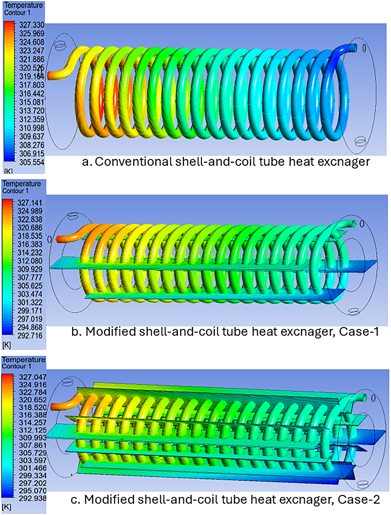
Figure 7: Temperature distribution in the coiled tube of the shell-and-coil tube heat exchanger: (a) Conventional; (b) Modified Case-1; (c) Modified Case-2
The cold part temperature contours of the modified heat exchanger and the standard shell and coil heat exchanger are presented in Fig. 8a–c. The temperature gradients in the improved heat exchanger are noticeable in the illustrated figures, and they indicate the mechanism of transferring the heat from the coiled pipe to the shell part fluid. The temperature contours that were obtained fit that design’s streamline formation. However, with a normal heat exchanger, temperature gradients are rarely perceptible, even as the temperature rises gradually from the inlet to the outlet.

Figure 8: Temperature distribution in the shell part of the shell-and-tube heat exchanger: (a) Conventional; (b) Modified Case-1; (c) Modified Case-2
The improved heat exchanger makes it easy to identify the three-dimensional temperature gradients that have developed around the coil. Heat transfer from one medium to another is the main function of a heat exchanger. The differential temperature between the flows’ intake and exit, and therefore the output temperatures, are crucial indicators of a heat exchanger’s performance in heat transfer techniques that do not include phase change. The hot fluid exit temperatures of a modified heat exchanger and a conventional heat exchanger with various flow rates of the cold fluid and a specified flow rate of 3 L/min of the hot fluid are illustrated in Fig. 9.
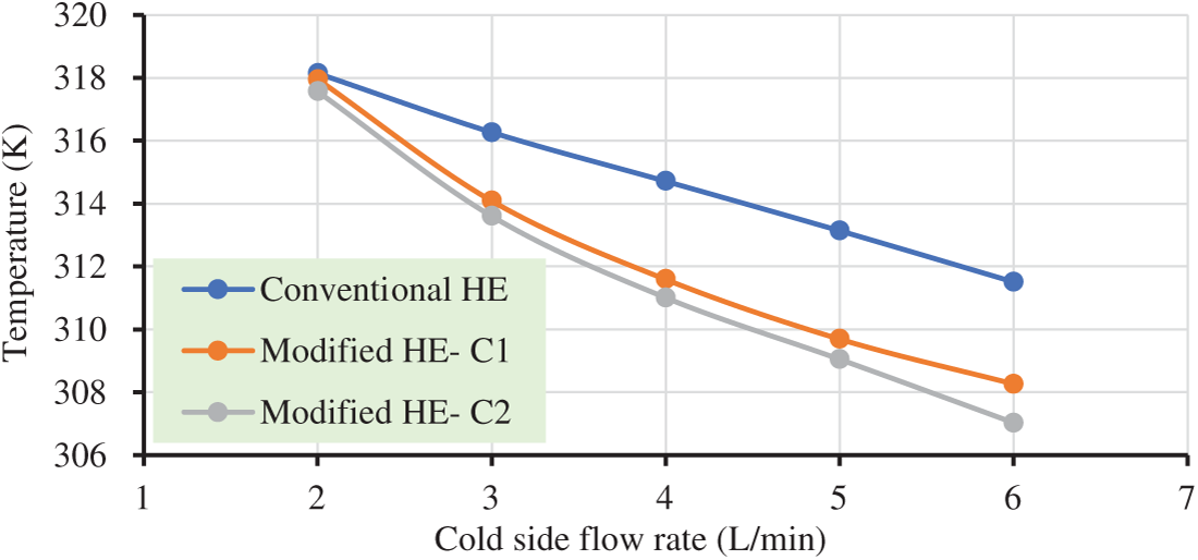
Figure 9: Hot side outlet temperatures in relation to flow rate
A critical indicator of improved heat transfer is the rise in output temperatures. It should be mentioned that the outcomes of the simulations showed that the second case of the improved heat exchanger performed better regarding outlet temperatures, which is due to the application of longitudinal fins to the coiled tube that resulting greater heat transfer area. Fig. 9 makes it evident that the second case improved coil heat exchanger, has decreased the hot fluid outlet temperatures more than the first case of improved and conventional SCHE at all flow rates, due to the combination effect of fins and slots that enhanced enlargement in the heat transfer surface area, resulted in boosted flow turbulence.
The cold fluid outlet temperatures of both cases of a modified heat exchanger and a conventional heat exchanger, with specified range flow rates of cold fluid and at a flow rate value of 3 L/min of hot fluid, are displayed in Fig. 10. The second case of the modified system’s cold fluid outlet temperatures is higher than the conventional system’s at all flow rates.
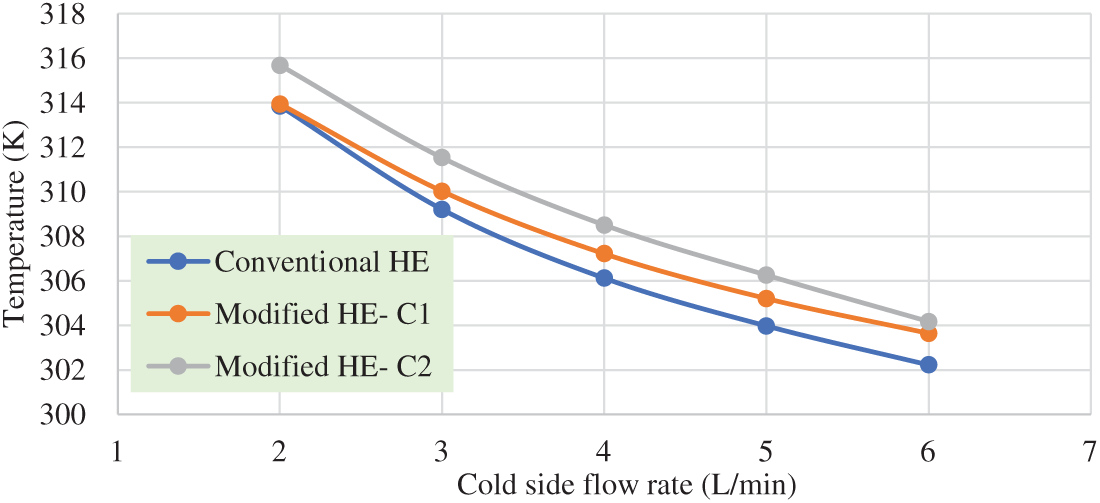
Figure 10: Cold side outlet temperatures in relation to flow rate
An essential component of evaluating heat exchanger performance is the average amount of heat transfer, which can be computed using the variations in inlet and exit temperatures as explained in the above sections. The computed average heat transfer quantities for the three simulated models are displayed in Fig. 11 in relation to the rise in the flow rate of the cold fluid at a distinct hot flow rate of 3 L/min. As it was shown, the fin effect, which was represented by C2, can be chosen as the most effective case. It might be stated that the heat exchange was improved by the improved heat exchanger in both modification cases resulted in more turbulence rate, but case 2 represented higher modification scales as compared to the first case modified and the conventional coiled tube heat exchanger. In the second case, with a larger surface area of the heat transferred region, the modified heat exchanger operating at a hot fluid flow rate of 3 L/min, the average heat transfer varied between 3298.0315 and 5337.3 W, while in the conventional design, it varied between 3110.3 and 4462.8 W. For modeling with hot fluid flow rates of 3 L/min, the average boosting in the average rate of heat transfer was determined to be 15.56% resulted from combined effect of slots and fins supported to enhance heat transfer rate.

Figure 11: Average rate of heat transfer relative to flow rate
Another crucial factor in heat exchanger design is the coefficient of overall heat transfer, which is a measurement of the efficacy of heat transmission in the heat exchanger’s contact surfaces. The situations are described in Fig. 12. Overall heat transfer coefficients for the second case of the modified heat exchanger, which included longitudinal fins, range from 1024.4 to 1596.6 W/(m2·K), while those for the conventional heat exchanger are calculated to be between 892.6 and 1157.9 W/(m2·K). The average value of the coefficient of overall heat transfer increases by an average of 29.51% as a result of the changes implemented.

Figure 12: Cold side coefficient of overall heat transfer in relation to flow rates
The coefficient of convective heat transfer (h) computed for modified and standard heat exchangers is contrasted in Fig. 13. According to calculations, the second case modified heat exchanger’s convective heat transfer coefficients at a hot fluid flow rate of 3 L/min range from 1437.54 to 3072.7 W/(m2·K), whereas the conventional heat exchanger’s coefficients range from 1051.1 to 1553.3 W/(m2·K). According to the results, the convective coefficient of heat transfer increased by an average of 75.96% for a 3 L/min flow rate of the hot fluid.

Figure 13: Cold side convective heat transfer coefficient in relation to flow rates
Numerical pressure drop values in conventional and modified coil heat exchangers with respect to cold side flow rates are presented in Fig. 14. It is evident that the addition of slots and fins increased the pressure drop in the coil heat exchanger’s cold side. The average increase in pressure drop value reached 10.72%, which is quite normal. The application of fins reported the highest values of the pressure drop as they enhanced turbulence; however, they caused much energy losses due to irregular and chaotic fluid motion.
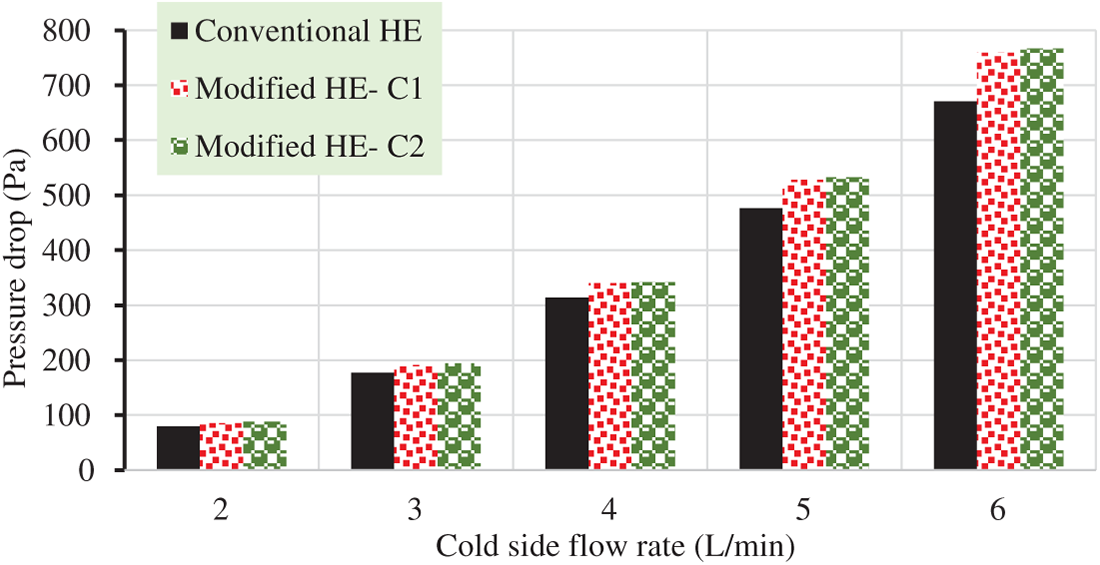
Figure 14: Cold side pressure drops in relation to flow rates
In the current work, the CFD theorem was performed to develop the performance of two models of coil heat exchangers, named C1 and C2, and compare the thermal properties of modified models with the conventional one. Overall outcomes indicated acceptable results which can be summarized as:
1. Due to the high turbulence caused by the modified models, as it was presented in streamlines and the contours of the temperature in both hot and cold sides with a hot side flow rate of 3 L/min, better cooling capacity in the hot side was reported.
2. Higher rate of heat transfer, convective heat transfer coefficient, and overall heat transfer coefficient resulted as their average increase values were 15.56%, 75.96% and 29.51%, respectively.
3. The results revealed that configuration alteration of the conventional coil heat exchanger by adding longitudinal slots and fins inside the shell enhances the heat exchanger’s thermal performance.
4. The modified technique applied in both case-1 and case-2 resulted in high amount of pressure drop.
To achieve further thermal improvement, several nanofluids could be investigated as working fluids in subsequent research, and also further insight of the slots and fins dimensions may lead to optimized configuration of the modified coil heat exchanger.
Acknowledgement: We would like to express my sincere gratitude to both of my collaborators for their invaluable guidance, support, encouragement, and for providing the necessary resources.
Funding Statement: The authors received no specific funding for this study.
Author Contributions: Include conceptualization and supervision, by Ranj Sirwan Abdullah and Ahmed Mohammed Adham; validation, formal analysis, investigation and original manuscript preparation, by Najiba Hasan Hamad; resources, by Najiba Hasan Hamad and Ahmed Mohammed Adham. All authors reviewed the results and approved the final version of the manuscript.
Availability of Data and Materials: Not applicable.
Ethics Approval: Not applicable.
Conflicts of Interest: The authors declare no conflicts of interest to report regarding the present study.
Nomenclature
| A | Contact region area (m2) |
| C1 | Case 1 |
| C2 | Case 2 |
| Cp | Specific heat capacity (kJ/(kg·K)) |
| E | Kinetic energy (J) |
| G | Specific internal energy (J) |
| hj | Enthalpy flux associated with mass diffusion. |
| H | Convective heat transfer coefficient (W/(m2·K)) |
| I | Identity tensor |
| K | Thermal conductivity (W/(m·K)) |
| P | Pressure (N m) |
| Q | Heat transfer (W) |
| S-CTHE | Shell-and-coil tube heat exchanger |
| T | Temperature (K) |
| Velocity gradient tensor | |
| Velocity gradient tensor transpose | |
| U | Velocity (m/s) |
References
1. Gokulnathan E, Pradeep S, Jayan N, Laxmi Deepak Bhatlu M, Karthikeyan S. Review of heat transfer enhancement on helical coil heat exchanger by additive passive method. Mater Today Proc. 2021;37:3024–7. doi:10.1016/j.matpr.2020.08.725. [Google Scholar] [CrossRef]
2. Yılmaz MS, Ünverdi M, Kücük H, Akcakale N, Halıcı F. Enhancement of heat transfer in shell and tube heat exchanger using mini-channels and nanofluids: an experimental study. Int J Therm Sci. 2022;179:107664. doi:10.1016/j.ijthermalsci.2022.107664. [Google Scholar] [CrossRef]
3. Inyang UE, Uwa IJ. Heat transfer in helical coil heat exchanger. Adv Chem Eng Sci. 2022;12(1):26–39. doi:10.4236/aces.2022.121003. [Google Scholar] [CrossRef]
4. Jalilian S, Momeni M, Fartaj A. Enhancing thermal performance and optimization strategies of PCM-integrated slab-finned two-fluid heat exchangers for sustainable thermal management. J Energy Storage. 2024;75:109587. doi:10.1016/j.est.2023.109587. [Google Scholar] [CrossRef]
5. Naphon P, Wongwises S. Investigation of the performance of a spiral-coil finned tube heat exchanger under dehumidifying conditions. J Eng Phys Thermophys. 2003;76(1):83–92. doi:10.1023/A:1022967208737. [Google Scholar] [CrossRef]
6. Onal BS, Kirkar SM, Akgul D, Celen A, Acikgoz O, Dalkilic AS, et al. Heat transfer and pressure drop characteristics of two phase flow in helical coils. Therm Sci Eng Prog. 2022;27:101143. doi:10.1016/j.tsep.2021.101143. [Google Scholar] [CrossRef]
7. Ghorbani N, Taherian H, Gorji M, Mirgolbabaei H. Experimental study of mixed convection heat transfer in vertical helically coiled tube heat exchangers. Exp Therm Fluid Sci. 2010;34(7):900–5. doi:10.1016/j.expthermflusci.2010.02.004. [Google Scholar] [CrossRef]
8. Bai X, Luo T, Cheng K, Chai F. Experimental study on fouling in the heat exchangers of surface water heat pumps. Appl Therm Eng. 2014;70(1):892–5. doi:10.1016/j.applthermaleng.2014.06.009. [Google Scholar] [CrossRef]
9. Tuncer AD, Sözen A, Khanlari A, Yağız Gürbüz E, Variyenli HI. Experimental and numerical analysis of a new modification for enhancing thermal performance of a shell and helically coiled heat exchanger. Appl Therm Eng. 2020;184:116272. doi:10.1016/j.applthermaleng.2020.116272. [Google Scholar] [CrossRef]
10. Abdullah M, Hussein A. Impact of coil pitch on heat transfer enhancement of a turbulent flow of α-Al2O3/DW nanofluid through helical coils. Therm Sci. 2023;27(6 Pt B):5005–14. doi:10.2298/tsci230227131a. [Google Scholar] [CrossRef]
11. Abdelmagied M. Numerical analysis on heat transfer enhancement of Al2O3 and CuO-water nanofluids in annular curved tubes. Int J Air Cond Refrig. 2025;33(1):1. doi:10.1007/s44189-024-00066-8. [Google Scholar] [CrossRef]
12. Miansari M, Jafarzadeh A, Arasteh H, Toghraie D. Thermal performance of a helical shell and tube heat exchanger without fin, with circular fins, and with V-shaped circular fins applying on the coil. J Therm Anal Calorim. 2021;143(6):4273–85. doi:10.1007/s10973-020-09395-3. [Google Scholar] [CrossRef]
13. Hameed VM, Hamad FJ. Implementation of novel triangular fins at a helical coil heat exchanger. Chem Eng Process Process Intensif. 2022;172:108745. doi:10.1016/j.cep.2021.108745. [Google Scholar] [CrossRef]
14. Tahmasbi M, Siavashi M, Karimi AR, Tousi R, Keshtkaran AH. The effects of fins number, metal foam, and helical coil on the thermal storage enhancement of the phase change material: an experimental study. Appl Therm Eng. 2024;253:123780. doi:10.1016/j.applthermaleng.2024.123780. [Google Scholar] [CrossRef]
15. Vahidifar S, Kahrom M. Experimental study of heat transfer enhancement in a heated tube caused by wire-coil and rings. J Appl Fluid Mech. 2015;8(4):885–92. doi:10.18869/acadpub.jafm.67.223.23359. [Google Scholar] [CrossRef]
16. Mohite PP, Kadam KD, Acharya AR, Pise A. Enhancement in heat transfer by using wire coil inserts in tubular heat exchanger. Int J Res Appl Sci Eng Technol. 2018;6(6):1635–40. doi:10.22214/ijraset.2018.6240. [Google Scholar] [CrossRef]
17. Dang W, Wang LB. Convective heat transfer enhancement mechanisms in circular tube inserted with a type of twined coil. Int J Heat Mass Transf. 2021;169:120960. doi:10.1016/j.ijheatmasstransfer.2021.120960. [Google Scholar] [CrossRef]
18. Hossen A, Chowdhury MS, Inam MI. The effects of dimples on heat transfer and fluid flow on a circular tube: a computational investigation. In: Proceedings of the International Conference on Industrial & Mechanical Engineering and Operations Management; 2021 Dec 26–27; Dhaka, Bangladesh. [Google Scholar]
19. Bdaiwi M, Akroot A, Abdul Wahhab HA, Assaf YH, Nawaf MY, Talal W. Enhancement heat exchanger performance by insert dimple surface ball inside tubes: a review. Results Eng. 2023;19:101323. doi:10.1016/j.rineng.2023.101323. [Google Scholar] [CrossRef]
20. Malapur HV, Havaldar SN, Kharade UV. Heat transfer enhancement of an internally and externally dimpled pipe heat exchanger—numerical study. Mater Today Proc. 2022;63:587–94. doi:10.1016/j.matpr.2022.04.155. [Google Scholar] [CrossRef]
21. Hashemi Karouei SH, Jasim DJ, Fares MN, Sabri LS, Al-Shati AS. Numerical investigation of the simultaneous effect of twisted tape and nanofluid hybrid in shell and spiral tube heat exchanger with a special design. Case Stud Therm Eng. 2024;64:105397. doi:10.1016/j.csite.2024.105397. [Google Scholar] [CrossRef]
22. Mohebi S, Tavakoli MR, Fattahi A. Numerical thermal-hydrodynamical modeling of a multi-bladed twisted tape inserted in a double-pipe heat exchanger: a comparative study. J Therm Anal Calorim. 2025;150(10):7753–65. doi:10.1007/s10973-025-14066-2. [Google Scholar] [CrossRef]
23. Abed AM, Kanabar B, Ramachandran T, Shankhyan A, Chohan JS, Karthikeyan A, et al. Hydrothermal behavior of a novel conical twisted strip turbulator in a heated tube: a numerical analysis. Case Stud Therm Eng. 2025;71:106186. doi:10.1016/j.csite.2025.106186. [Google Scholar] [CrossRef]
24. Al-Mosallam M, Ali ABM, Shrama SM, Fares MN, Hashemi Karouei SH, Jasim DJ, et al. Numerical study of the heat transfer characteristics of two distinct spiral coil configurations with the insertion of twisted tape in a shell and tube heat exchanger. Case Stud Therm Eng. 2025;74:106672. doi:10.1016/j.csite.2025.106672. [Google Scholar] [CrossRef]
25. Lazim TM, Kareem ZS, Mohd Jaafar MN, Abdullah S, Abdulwahid AF. Heat transfer enhancement in spirally corrugated tube. Int Rev Model Simul. 2014;7(6):970. doi:10.15866/iremos.v7i6.4948. [Google Scholar] [CrossRef]
26. Çolak AB, Kirkar SM, Gönül A, Dalkilic AS. Assessment of heat transfer characteristics of a corrugated heat exchanger based on various corrugation parameters using artificial neural network approach. Int J Heat Fluid Flow. 2024;108:109455. doi:10.1016/j.ijheatfluidflow.2024.109455. [Google Scholar] [CrossRef]
27. Nayak S, Jena S, Khan ASS, Paswan MK, Sharma VK. Use of corrugated pipe heat exchangers in waste heat recovery steam generators. IOP Conf Ser Mater Sci Eng. 2021;1123(1):012037. doi:10.1088/1757-899x/1123/1/012037. [Google Scholar] [CrossRef]
28. Córcoles JI, Belmonte JF, Molina AE, Almendros-Ibáñez JA. Influence of corrugation shape on heat transfer performance in corrugated tubes using numerical simulations. Int J Therm Sci. 2019;137:262–75. doi:10.1016/j.ijthermalsci.2018.11.021. [Google Scholar] [CrossRef]
29. Heydari O, Miansari M, Arasteh H, Toghraie D. Optimizing the hydrothermal performance of helically corrugated coiled tube heat exchangers using Taguchi’s empirical method: energy and exergy analysis. J Therm Anal Calorim. 2021;145(5):2741–52. doi:10.1007/s10973-020-09808-3. [Google Scholar] [CrossRef]
30. Chen H, Moria H, Ahmed SY, Nisar KS, Mohamed AM, Heidarshenas B, et al. Thermal/exergy and economic efficiency analysis of circumferentially corrugated helical tube with constant wall temperature. Case Stud Therm Eng. 2021;23:100803. doi:10.1016/j.csite.2020.100803. [Google Scholar] [CrossRef]
31. Hundiwale A, Gaikwad L, Joshi S. Design and analysis of helical cone coil heat exchanger for low-grade heat recovery. J Heat Mass Transfer Res. 2025;12(1):61–72. doi:10.22075/jhmtr.2024.33519.1533. [Google Scholar] [CrossRef]
32. Güngör A, Khanlari A, Sözen A, Variyenli HI. Numerical and experimental study on thermal performance of a novel shell and helically coiled tube heat exchanger design with integrated rings and discs. Int J Therm Sci. 2022;182:107781. doi:10.1016/j.ijthermalsci.2022.107781. [Google Scholar] [CrossRef]
33. Hamied MA, Atta M, García-Regodeseves P, Ríos-Fernández JC. A novel sequential approach through structural enhancements for designing a new serrated helical heat exchanger. Case Stud Therm Eng. 2025;69:106006. doi:10.1016/j.csite.2025.106006. [Google Scholar] [CrossRef]
34. Jiang H, Jiang T, Tian H, Wu Q, Deng C, Zhang R. Heat transfer simulation and structural optimization of spiral fin-and-tube heat exchanger. Electronics. 2024;13(23):4639. doi:10.3390/electronics13234639. [Google Scholar] [CrossRef]
35. Bacak AY, Khanlari A, Tuncer AD, Sözen A, Variyenli Hİ, Vafai K. A comprehensive numerical and experimental study on improving the thermal performance of a shell and helically coiled heat exchanger utilizing hybrid magnetic nanofluids and porous spiral-type fins. Fluids. 2025;10(6):141. doi:10.3390/fluids10060141. [Google Scholar] [CrossRef]
36. Lewis RW, Nithiarasu P, Seetharamu KN. Fundamentals of the finite element method for heat and fluid flow. Hoboken, NJ, USA: John Wiley & Sons; 2004. doi:10.1002/0470014164. [Google Scholar] [CrossRef]
37. Afshari F, Sözen A, Khanlari A, Tuncer AD, Şirin C. Effect of turbulator modifications on the thermal performance of cost-effective alternative solar air heater. Renew Energy. 2020;158:297–310. doi:10.1016/j.renene.2020.05.148. [Google Scholar] [CrossRef]
38. Hamad NH, Bilal M, Ali A, Eldin SM, Sharaf M, Rahman MU. Energy transfer through third-grade fluid flow across an inclined stretching sheet subject to thermal radiation and Lorentz force. Sci Rep. 2023;13(1):19643. doi:10.1038/s41598-023-46428-x. [Google Scholar] [PubMed] [CrossRef]
39. Çiftçi E, Khanlari A, Sözen A, Aytaç İ, Tuncer AD. Energy and exergy analysis of a photovoltaic thermal (PVT) system used in solar dryer: a numerical and experimental investigation. Renew Energy. 2021;180:410–23. doi:10.1016/j.renene.2021.08.081. [Google Scholar] [CrossRef]
40. Ghaderi A, Veysi F, Aminian S, Andami Z, Najafi M. Experimental and numerical study of thermal efficiency of helically coiled tube heat exchanger using ethylene glycol-distilled water based Fe3O4 nanofluid. Int J Thermophys. 2022;43(8):118. doi:10.1007/s10765-022-03041-w. [Google Scholar] [CrossRef]
41. Gomaa A, Gamal Y, Abdelmagied MM. Enhancement of thermofluid characteristics via a triple-helical tube heat exchanger. Sci Rep. 2025;15(1):6978. doi:10.1038/s41598-025-89730-6. [Google Scholar] [PubMed] [CrossRef]
42. Alikhan AHD, Al-Ogaili KSJ, Mery HO. Experimental assessment of plate heat exchanger performance enhancement by compound pulsating and low concentration CuO nanoadditive methods. Int J Heat Technol. 2025;43(2):428–36. doi:10.18280/ijht.430205. [Google Scholar] [CrossRef]
Cite This Article
 Copyright © 2026 The Author(s). Published by Tech Science Press.
This work is licensed under a Creative Commons Attribution 4.0 International License , which permits unrestricted use, distribution, and reproduction in any medium, provided the original work is properly cited.
 Downloads
 Citation Tools