
 Login
Login Register
 Submit a Paper
 Propose a Special lssue
 Open Access
ARTICLE
Active Thermal Control for Lifetime Extension of Wind Power Converter
1 China Southern Power Grid Scientific Research Institute Co., Ltd., Guangzhou, China
2 School of Electrical Engineering, Shanghai Jiao Tong University, Shanghai, China
* Corresponding Author: Renxin Yang. Email:
Energy Engineering 2026, 123(11), 10 https://doi.org/10.32604/ee.2026.075636
Received 05 November 2025; Accepted 12 January 2026; Issue published 24 September 2026
 View Full Text
 Download PDF
Abstract
With the rapid development of renewable energy, the proportion of wind power generation in modern power systems has been steadily increasing. Benefiting from the high controllability of power electronic converters, wind energy can be efficiently transmitted to the grid through power conversion stages. However, the reliability of wind turbine systems is closely related to the thermal stress and degradation of power semiconductor devices. The diversity of actual operating conditions and the rapid fluctuations of grid load bring significant challenges to their safe and stable operation. To address these issues, this paper establishes an online electro-thermal model of the wind power converter, enabling real-time estimation of power loss and junction temperature. Two typical scenarios—grid frequency disturbance and grid voltage fault—are analyzed to evaluate their impact on device lifetime. Based on the modeling results, an active thermal control (ATC) strategy is proposed to dynamically suppress junction temperature fluctuations and thereby extend the converter’s service life. Finally, simulations are conducted using PLECS to validate the effectiveness of the proposed method. The results demonstrate that the ATC scheme can effectively reduce the junction temperature swing and improve the lifetime of power semiconductor devices without affecting power conversion performance, providing a practical approach for enhancing the reliability of wind power converters.Keywords
With the continuous growth of renewable energy installations, the share of new energy generation units, represented by wind and photovoltaic power, in modern power systems has been steadily increasing [1]. As the critical interface between renewable energy sources and the power grid, the grid-connected inverter plays an essential role in ensuring reliable power conversion and grid stability [2,3]. However, the rapid expansion of power electronic applications has also increased the risk and severity of potential failures, making the safety and reliability of power electronic conversion systems one of the key concerns in current research.
According to statistical reports, in practical wind power generation systems, power electronic converters account for more than 50% of total failures, among which power semiconductor devices contribute the highest proportion—approximately 31%, as shown in Fig. 1 [4]. As one of the most critical components in power conversion systems, semiconductor devices dissipate large amounts of power and undergo repetitive electro-thermal cycling, leading to accelerated aging and eventual device failure [5,6]. Consequently, active thermal control (ATC) methods for IGBTs have been proposed to alleviate internal electro-thermal stress [7]. Generally, the internal thermal stress of IGBTs can be classified into two types [8]: steady-state thermal stress, caused by long-term thermal cycling, and transient overstress, induced by short-term thermal fluctuations. Some studies have proposed specific ATC strategies through modifying gate drivers [9], adjusting modulation schemes [10], or varying the switching frequency [11]. However, these approaches mainly focus on mitigating steady-state thermal stress under long-term operating conditions. In contrast, the transient electro-thermal overstress caused by short-term grid disturbances—such as shutdowns, load switching, and short-circuit faults—also plays a significant role in device degradation within a short timescale. Nevertheless, relevant studies on this aspect remain relatively limited.
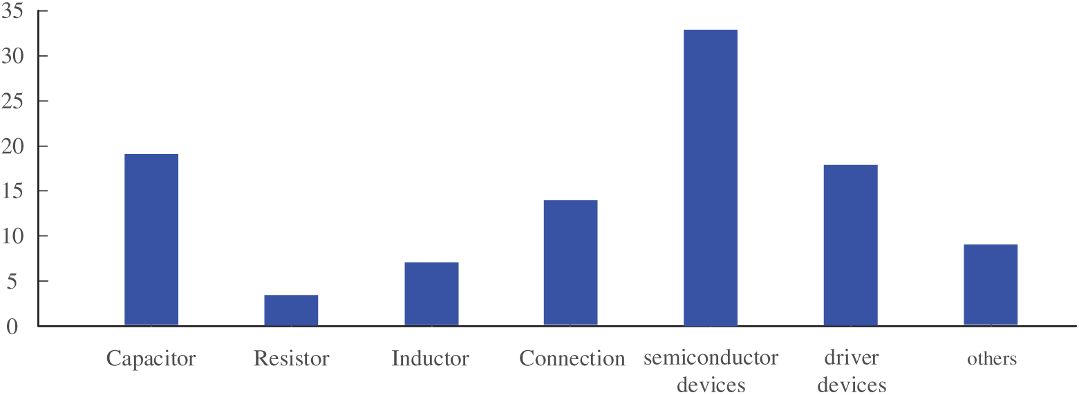
Figure 1: Failure mode distribution of components in converters.
In the field of motor drive applications, Ref. [12] proposed an active thermal control method that determines the optimal phase angle under motor stall conditions. While maintaining the effectiveness of the original current control loop, the method redistributes and minimizes the overall thermal stress of the three-phase currents, thereby reducing both the junction temperature and total power loss of the semiconductor devices. Similarly, Ref. [13] presented an adaptive voltage control method for motor stalling conditions, in which the power loss model of the semiconductor devices was reconstructed to redistribute power dissipation, achieving significant reductions in total loss and junction temperature during motor stall. However, these studies mainly focus on short-term overstress during motor stall and are not directly applicable to wind power converters experiencing transient grid faults. Reference [14] reported that small-scale doubly-fed induction generators (DFIGs) exhibit substantial junction temperature fluctuations during severe grid voltage dips, with instantaneous current surges upon voltage recovery that cause junction temperature increases of up to 50%. In addition, Ref. [15] analyzed the dynamic electro-thermal stress of DFIG converters under transient grid faults and pointed out that when the grid voltage symmetrically drops below half its nominal value, both the steady-state fluctuation and the maximum junction temperature of the converter’s IGBTs rise significantly, with a peak increase close to 50%. A hysteresis-based switching frequency control framework is designed in [16] to reduce the excessive temperature rise caused by overload conditions in electric drive systems. Nevertheless, the above studies merely identified the occurrence of transient thermal shocks during grid faults but did not propose corresponding active thermal control solutions. Some other works have investigated the influence of different modulation strategies on the junction temperature and lifetime of power semiconductor devices under specific operating conditions. For instance, Refs. [17,18] analyzed the effect of modulation strategies on the junction temperature of three-level converters in wind turbine low-voltage ride-through (LVRT) conditions; Ref. [19] used finite element analysis to compare the thermal impact of sinusoidal pulse width modulation (SPWM) and space vector pulse width modulation (SVPWM) in two-level converters; and Ref. [20] discussed the temperature variations among different chips within three-level converters under various modulation schemes. Furthermore, Ref. [21] evaluated the reliability of converters under SPWM and SVPWM control, while Ref. [22] investigated lifetime differences among switching sequences based on power cycling tests. It can be observed that the existing studies mainly focus on steady operating conditions, assessing the impact of modulation strategies on device temperature or lifetime. However, the transient operation scenarios have not been adequately addressed. Since the disturbances caused by grid frequency and voltage faults are far more severe than those under normal operating conditions, wind power converters are required to maintain enhanced reliability and adaptability under grid disturbances [23].
Therefore, this paper focuses on the operating conditions of wind power converters under grid faults. Unlike most existing studies that mainly address steady-state thermal management or normal operating conditions, this work investigates the thermal reliability of wind power converters subjected to grid disturbances. First, a detailed loss and junction temperature calculation model of the power semiconductor devices is established to characterize fault-induced thermal behavior. Then, a junction-temperature-based lifetime evaluation model is developed to quantify the impact of transient temperature fluctuations on device reliability. More importantly, an active thermal control (ATC) method based on adaptive switching-frequency adjustment is proposed for grid fault scenarios, which explicitly considers the multi-time-scale interaction among grid transients, converter control dynamics, and device-level thermal stress. By dynamically regulating the switching frequency under fault conditions with stability-aware constraints, the proposed method effectively reduces both the fluctuation and peak value of junction temperature, thereby extending the converter lifetime. Finally, the proposed approach is validated through PLECS simulations under representative grid fault conditions.
The remainder of this paper is organized as follows. Section 2 introduces the control strategies of the wind power converter, as well as the corresponding fault ride-through (FRT) scheme. Section 3 establishes the calculation models for power device loss, junction temperature, and lifetime evaluation of the wind power converter. Section 4 proposes the active thermal control scheme based on adaptive switching-frequency regulation. Finally, Section 5 presents the simulation results to verify the effectiveness of the proposed method.
2 Control Structure of Grid-Connected Wind Power Converters
Taking a direct-drive wind turbine system based on a permanent magnet synchronous generator (PMSG) as an example, the corresponding circuit and control block diagram are shown in Fig. 2. In this figure, isdq and usdq represent the current and voltage of the machine-side converter (MSC), while isdqref denote the reference current values of the MSC. ωr is the rotor speed of the PMSG, and Lr is the rotor inductance. Pref is the optimal power reference, Pm is the output active power of the MSC, usd and usq correspond to the modulation voltages of the MSC, and Sr represents the switching signals of the MSC. For the grid-side converter (GSC), udq and idq correspond to its voltage and current, while idqref represent the dq-axis reference currents of the GSC. Lf is the filter inductor and ωg is the grid frequency. usdq represents the voltage at the point of common coupling (PCC), which is processed by a phase-locked loop (PLL) to obtain the phase angle θg required for GSC modulation. udcref and udc are the reference value and the measured feedback value of the DC-link voltage, respectively. Sm and Sg represent the switching signals of the MSC and GSC, respectively.
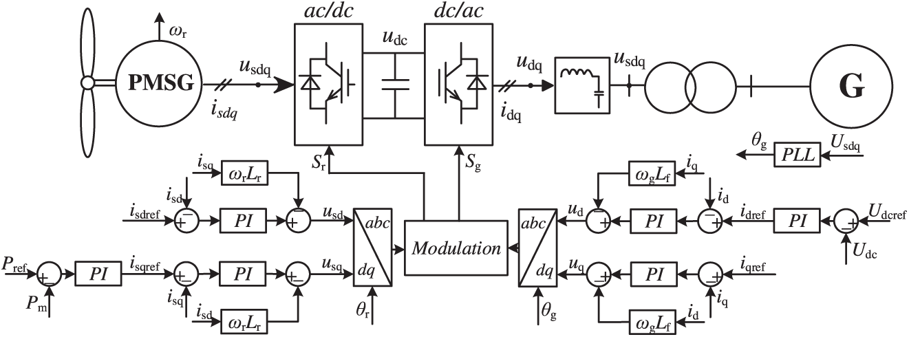
Figure 2: Control block diagram of a grid-connected direct-drive PMSG wind power converter.
2.1 Control of Machine-Side Converter
First, the outer control loop of the MSC performs maximum power point tracking (MPPT). Based on the current wind speed, the corresponding optimal power Pref is obtained from a lookup table and then fed into a PI controller to generate the current reference for the inner loop:
where Kpp and Kpi are the proportional and integral gains of the power PI controller, respectively. Kin is the inertia response coefficient, which is used to adjust the output power of the MSC according to the rate of change of the grid frequency ωg, so as to provide frequency support during grid frequency variations.
Then, the current reference generated in Eq. (1) is compared with the measured current, and the error is fed into the current controller to generate the corresponding modulation voltage signal:
Finally, the generated modulation voltage usdq is sent to the modulation block and compared with the carrier signal to obtain the switching signals Sr of the MSC.
2.2 Control of Grid-Side Converter
For the grid-side converter (GSC), the outer control loop is responsible for regulating the DC-link voltage to a constant value, and generates the corresponding current reference for the inner control loop:
Then, the current reference generated in Eq. (3) is compared with the measured current, and the error is fed into the current controller to generate the corresponding modulation voltage signal:
where Lf represents the filter inductor at the output of the GSC. Based on Eqs. (3) and (4), the corresponding switching signals Sg for the GSC can be generated.
2.3 Control of Wind Power Converter under Grid Faults
For grid frequency disturbances, the wind power converter can provide inertia response as described in Eq. (1). Specifically, when the grid frequency ωg decreases, the active power reference Pref is increased by Kinsωg to support the recovery of the grid frequency. Conversely, when ωg increases, the active power output is reduced accordingly.
For grid voltage faults, the current limitation commands of the GSC need to be set according to the grid code requirements in order to support the voltage recovery during the fault [24]:
where Kc is the reactive power support coefficient defined in the grid code. When the PCC voltage us drops below 0.5 p.u., the converter outputs full reactive current to support the voltage recovery during the fault. When us is between 0.5 and 1 p.u., a portion of active current is still reserved while providing reactive current support.
Since the DC-link capacitor electrically decouples the MSC from the GSC, the MSC does not need to modify its control scheme during grid voltage faults. It is worth noting that, due to the reduced active power transfer capability on the GSC side during a voltage sag while the MSC continues to deliver active power, the DC-link voltage udc will rise accordingly. To protect the DC-link capacitor from overvoltage stress, a dedicated braking chopper circuit is implemented to dissipate the excess active power:
where R is the value of the unloading resistor, and udc0 denotes the steady-state DC-link voltage.
Based on Eqs. (1)–(6), the wind power converter is capable of achieving maximum power point tracking on the MSC side, DC-link voltage control on the GSC side, unity power factor operation under normal conditions, and safe operation during grid fault events.
3 Electrothermal Stress and Lifetime Model of Wind Power Converters
The junction temperature is closely associated with the operational lifetime and reliability of wind power converters. It originates from the power dissipation of semiconductor devices and, in turn, further affects their loss distribution. Therefore, this section first establishes the power loss and junction temperature calculation models for the converter. Based on these models, a lifetime prediction approach is subsequently developed to evaluate the reliability impact under various operating conditions.
Taking an IGBT-based power module as an example, the total losses consist of the conduction losses Pc and switching losses Psw of both the IGBT and its anti-parallel diode. The conduction and switching losses of the IGBT can be calculated as follows:
where fsw denotes the switching frequency of IGBT, ic denotes the current across the IGBT during conduction, Eon and Eoff denote the turn-on and turn-off energy of the IGBT, uref denotes the rated operating voltage of the module.
Similarly, the diode losses, including conduction loss PcD and switching loss PswD, can be calculated in the same way:
In this case, vf represents the forward voltage drop of the diode, and Err denotes its reverse-recovery energy.
It is noteworthy that both the conduction voltage drop and the switching energy are influenced by the current ic as well as the junction temperatures Tj and TjD. Therefore, these dependencies should be taken into account during the modeling process:
The parameters K1–K5 represent the temperature-dependent fitting coefficients for the loss characteristics, which can be obtained from the datasheet provided by the device manufacturer. Based on this modeling approach, a loss calculation model that incorporates the feedback effect of junction temperature is established. It can be observed that there exists a mutual coupling between loss and junction temperature: an increase in power loss raises the junction temperature, which in turn further influences the loss behavior.
3.2 Junction Temperature Calculation
Based on an analogy to electrical networks, thermal behavior in power semiconductor modules can be represented through equivalent thermal circuits. Two mainstream thermal modeling approaches are commonly used for power semiconductor devices: the Cauer model and the Foster model. The Cauer model establishes a direct correspondence between thermal elements and the physical layers of the power module, providing clear physical interpretability, but its construction requires detailed internal structural and material parameters that are typically unavailable and often relies on finite-element-based calibration. By contrast, the Foster model does not depend on the internal physical structure of the device and can be directly identified from measured transient thermal impedance under step power excitation [25,26]. From a dynamic modeling perspective, the Foster and Cauer models are mathematically equivalent realizations of linear thermal systems [27]. Considering its low parameter identification effort and suitability for online implementation, the Foster model as illustrated in Fig. 3 is adopted in this study for electro-thermal analysis and active thermal control, as it has been extensively validated in prior literature for its accuracy in junction temperature estimation. In this model, Rjc, Cjc, RjcD, and CjcD denote the thermal resistance and capacitance from the IGBT and diode junctions to the case, respectively. Rch and Cch represent the thermal path between the case and the heatsink. Rha and Cha describe the heatsink-to-ambient heat dissipation characteristics. Tc, Th, and Ta correspond to the case, heatsink, and ambient temperatures, respectively. The associated thermal resistances and time constants of the selected power module Skiip2414 GB17E4-4DUL are summarized in Table 1.
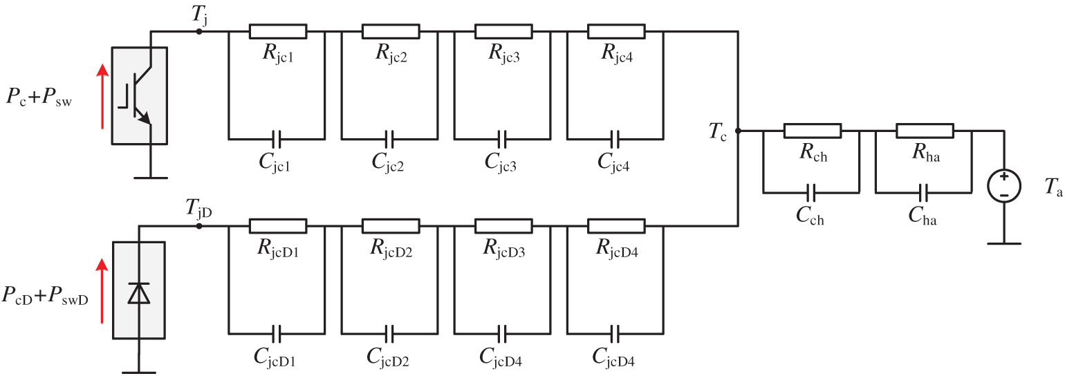
Figure 3: Junction temperature calculation model of an IGBT power module based on the Foster thermal network.

Fig. 3 shows the thermal propagation network of the chips inside the IGBT module. Under normal operating conditions, the IGBTs and diodes switch continuously and generate power losses, which accumulate and appear at the case and heatsink temperatures. Based on the measured case temperature, the junction temperatures of the semiconductor chips can be calculated using the established 4-order Foster thermal network. The temperature calculation methods for the IGBT and diode chips are given as follows:
where Tj denotes the junction temperature of IGBT, TjD denotes the junction temperature of diode, and Tc denotes the temperature of the module case; τi denotes the thermal time constant of each RC branch in the Foster network, representing the inertia of the junction temperature response to power loss variations and defined as the product of the corresponding thermal resistance and capacitance Rjci·Cjci. τch and τha represent the thermal time constants from the module case to the heatsink and from the heatsink to the ambient, respectively.
3.3 Lifetime Estimation of Power Electronic Devices
The aging and failure of power semiconductor devices are primarily induced by thermal stress, which acts on the interfaces between layers composed of materials with different coefficients of thermal expansion. During operation, varying mission profiles lead to fluctuations in power losses and consequently cause junction temperature cycling, resulting in cumulative thermomechanical fatigue. This process accelerates device degradation and may ultimately cause failure. The most common failure mechanisms include bond-wire lift-off and solder-layer fatigue [20]. Therefore, to further evaluate the reliability of power devices, this paper adopts the LESIT lifetime model [28] based on thermomechanical fatigue caused by junction temperature cycling, which can be expressed as:
where Nf represents the failure cycles of the device, meaning the total number of cycles during which the module can operate normally. The parameters a, b and c are the coefficients of the lifetime estimation model, obtained by the manufacturer through statistical fitting based on extensive aging tests. The term ΔTj refers to the junction temperature swing of IGBT, and Tavr denotes the average junction temperature. For power semiconductor devices such as IGBTs, the coefficient b is always negative, indicating that a larger junction temperature fluctuation will accelerate device degradation. Compared with the traditional Coffin-Manson model, this lifetime model in Eq. (11) incorporates the average junction temperature as an additional influencing factor, thereby enabling a more accurate prediction of device lifetime.
Subsequently, since real operating conditions typically involve varying thermal stress levels, the Lesit model alone is insufficient for lifetime estimation. During actual operation, the device will experience a certain number of cycles under each stress level. The ratio between the actual number of cycles and the allowable number of cycles represents the fraction of lifetime consumed at that stress level. Therefore, the Miner’s cumulative damage rule is adopted to evaluate the lifetime under non-uniform mission profiles.
here, cumulative damage is represented by D. The term ni denotes the actual number of thermal cycles experienced within the i-th stress range, while Nfi refers to the number of cycles to failure under that specific stress condition. When multiple thermal stress levels exist in the mission profile, the consumed lifetime fractions are summed together. Once the accumulated damage D reaches a value of 1, the power module is considered to have reached its wear-out failure point.
As a consequence, the maximum achievable lifetime of the power semiconductor devices is closely correlated with both the peak and mean junction temperatures. Any rise in either temperature metric results in a rapid, exponential reduction in the device’s operational lifetime.
4 Proposed Active Thermal Control Strategy
4.1 The ATC Framework for the IGBT in Wind Power Converter
Fig. 4 first illustrates the proposed ATC scheme based on the electrothermal model of IGBTs in the wind power converter system. In general, an online junction-temperature estimation is required to effectively implement ATC strategies, which corresponds to the modeling framework introduced in Eqs. (7)–(10). A conventional electrothermal model typically consists of three parts: a device model, a loss model, and a thermal network model. The physical system provides real-time measurement data as prerequisite inputs to the electro-thermal model. The device model obtains on-state voltage drops and switching energies through the polynomial fitting functions of loss-related variables as formulated in Eq. (9). Then, by applying the real-time loss computation model, the temporal evolution of chip losses can be evaluated. Finally, the accumulated loss is fed into the thermal network, and the corresponding junction temperature is obtained using the Foster-type thermal impedance model in Eq. (10).
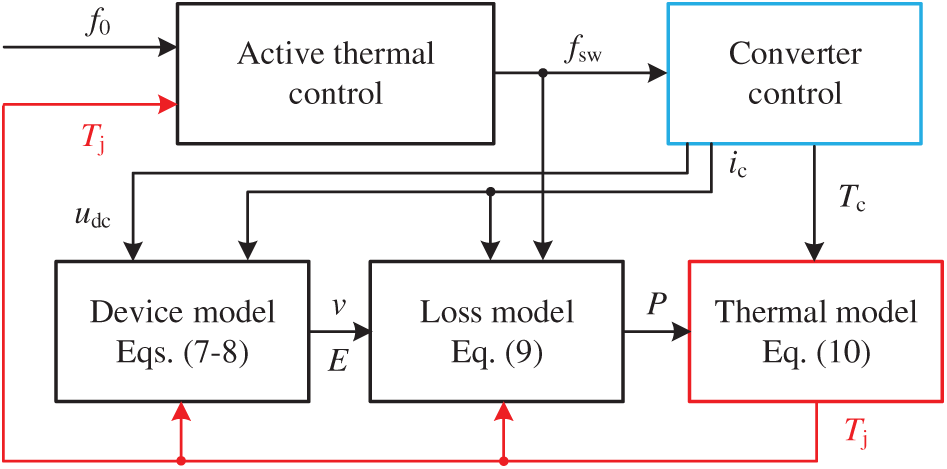
Figure 4: The proposed ATC framework based on electrothermal stress co-calculation feedback.
The ATC developed in this work is designed to suppress both the peak junction temperature and its accompanying thermal swing of power devices in wind power converters during grid transient faults. In contrast, most existing studies mainly focus on mitigating the maximum junction temperature or reducing the amplitude of long-term thermal cycles under load variations, and therefore cannot be directly applied to short-duration grid disturbances such as frequency and voltage fluctuations. Since the wind power converter operates under AC conditions, the junction-temperature ripple induced by the fundamental-frequency current becomes the primary factor affecting the reliability and lifetime of IGBTs. It is noteworthy that, according to (10) and Table 1, the junction temperature exhibits a significant delay with respect to the variation of power losses, namely, thermal inertia. When the losses experience a step change, the junction temperature typically requires several hundred milliseconds to reach its steady-state value. This inherent delay provides the feasibility for ATC implementation—i.e., by adjusting the switching stress immediately after a fault occurs but before the junction temperature reaches its maximum limit, the device can be effectively protected from overheating while enabling enhanced transient performance.
Fig. 5 presents a simple example to illustrate the influence of loss regulation on junction-temperature behavior. The AC loss amplitude is initially maintained at 50 W, resulting in an average junction temperature of approximately 50.2°C and a thermal swing of about 0.4°C. When the power loss steps to 150 W at t = 1.01 s, the junction temperature starts to rise accordingly. At t = 1.03 s, the average temperature increases to 52.1°C and the thermal swing expands to 2.0°C. However, as shown by the blue curve, if the power loss is reduced to 100 W at t = 1.015 s, the junction temperature immediately begins to decline. By t = 1.03 s, the average temperature decreases to 51.5°C and the thermal swing is suppressed to 1.5°C. These results demonstrate the feasibility of loss regulation for actively controlling the thermal stress of power devices. Therefore, it can be concluded that reducing the average junction temperature and its thermal swing essentially relies on effective loss mitigation. As long as the proposed ATC strategy adjusts the power loss before the junction temperature reaches the predefined maximum threshold, the temperature rise can be suppressed, which in turn improves the expected lifetime of the wind power converter under grid-fault conditions.
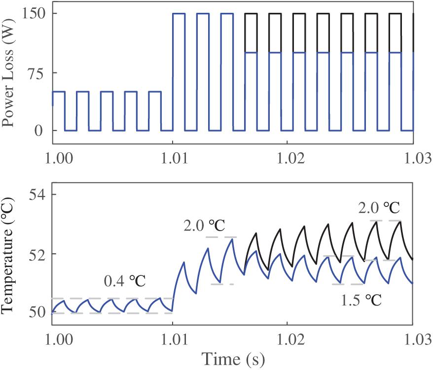
Figure 5: Illustration of the dynamic impact of power loss adjustment on junction temperature, highlighting the suppression of temperature fluctuation.
4.2 ATC Based on Switching Frequency
Based on Eqs. (6) and (7), the variables directly influencing the power device losses include the conduction current ic, switching frequency fsw, and DC-link voltage udc. For a wind power converter operating under grid-fault conditions, the output current amplitude is already dictated by the grid support requirements. Meanwhile, sufficient modulation depth must be guaranteed for the MSC to ensure maximum power tracking, thus udc cannot be freely adjusted. Consequently, the switching frequency fsw becomes the only controllable variable for loss mitigation. Since the objective of this work is to enhance the converter lifetime during grid transient disturbances by reducing the junction temperature and its fluctuation, the proposed ATC method is designed accordingly as follows:
where f0 denotes the initial switching frequency of the grid-side converter under normal steady-state operation, K6 represents the proportional coefficient used to adjust the switching frequency in the proposed active thermal control scheme. As shown in Fig. 5, because the wind power converter operates under AC conditions, the junction temperature still exhibits fluctuations even in steady-state operation. Therefore, a hysteresis coefficient K7 is introduced to avoid frequent switching-frequency changes caused by these steady-state temperature ripples. With the above design, the temperature information is directly linked to the switching frequency of the converter. Once the junction temperature exceeds the specified threshold Tn, the switching frequency begins to decrease linearly according to K6, thereby reducing the switching losses of the power devices. As a result, the junction temperature gradually decreases and eventually stabilizes at a new thermal equilibrium. It is worth noting that, considering the stability margin of the GSC control loop, the switching-frequency adjustment must be limited by a minimum threshold to ensure the stable operation of the wind power converter during grid faults, as illustrated in Fig. 6. The temperature threshold Tn is selected based on the steady-state operating point of the converter and is set slightly above the rated junction temperature to indicate the onset of increased thermal stress. The switching-frequency reduction is activated only when the predicted junction temperature exceeds this threshold, thereby avoiding unnecessary frequency variations during normal operation. Moreover, note that the proposed ATC is activated only during short-duration grid transient events. Within this limited time window, a moderate trade-off in harmonic performance is acceptable, provided that control stability is maintained and normal steady-state operation is fully restored after fault clearance.
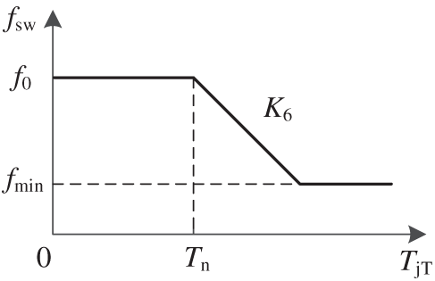
Figure 6: Diagram of junction-temperature-based dynamic switching-frequency adjustment.
Subsequently, the small-signal transfer-function block diagram of the cascaded voltage–current controller is established, as shown in Fig. 7. Based on this structure, the open-loop transfer function of the control loop can be expressed as:

Figure 7: Simulation results of the wind power converter under grid transient faults without the proposed ATC strategy.
where Tin denotes the time constant of the inner current control loop, Gdel(s) = e−sTd corresponds to a time delay. By substituting the parameters listed in Table 2, the Bode plots of the voltage transfer function under different switching frequencies are obtained, as shown in Fig. 8. It can be observed that, as the switching frequency decreases, the magnitude response gradually deteriorates and a resonance peak emerges in the high-frequency range. When the switching frequency is reduced to 0.5 f0, the magnitude response approaches 0 dB, indicating that the system operates at the stability boundary. Further reducing the switching frequency to 0.4 f0 results in a pronounced resonance peak exceeding 0 dB, implying loss of stability. Therefore, in practical control design, a minimum switching frequency should be imposed to ensure sufficient control bandwidth and stability margin. For the parameters adopted in this work, the minimum switching frequency is selected as 2000 Hz to avoid adverse impacts on the control loop bandwidth.
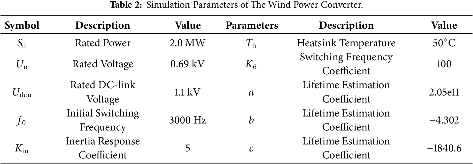
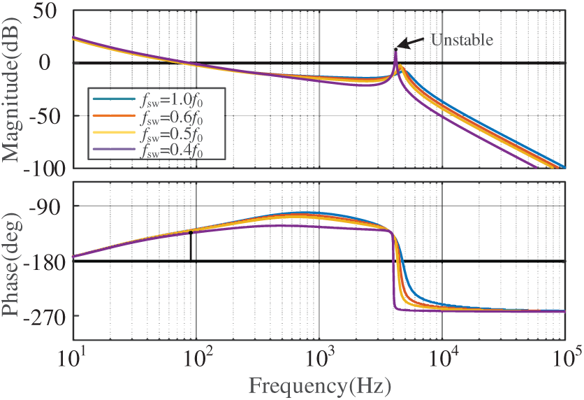
Figure 8: Simulation results of the wind power converter under grid transient faults without the proposed ATC strategy.
It should be noted that the proposed ATC strategy is not limited to the 2.0 MW converter considered in this study. Since its core mechanism relies on regulating switching frequency to mitigate device-level switching losses and junction temperature fluctuations across different time scales, the same control framework can be extended to converters with other power ratings and semiconductor technologies, with appropriate parameter re-tuning.
To verify the proposed ATC method, a 2.0 MW direct-drive PMSG-based wind power generation system model was developed in PLECS, and its electrical and thermal parameters are listed in Table 2. First, the electro-thermal stress and the corresponding expected lifetime of the wind power converter without enabling ATC are evaluated. Two typical grid disturbance scenarios are considered: a grid frequency fault and a grid voltage fault. The simulation results are shown in Fig. 9a,b, respectively. In Fig. 9a, the grid frequency drops at a rate of 0.5 Hz/s at t = 2 s until it reaches 49 Hz, and then recovers to the nominal value of 50 Hz at the same rate at t = 4 s. In Fig. 9b, the grid voltage experiences a three-phase symmetrical voltage sag down to 0.2 p.u. at t = 3 s and remains at that level until the fault is cleared at t = 3.625 s.
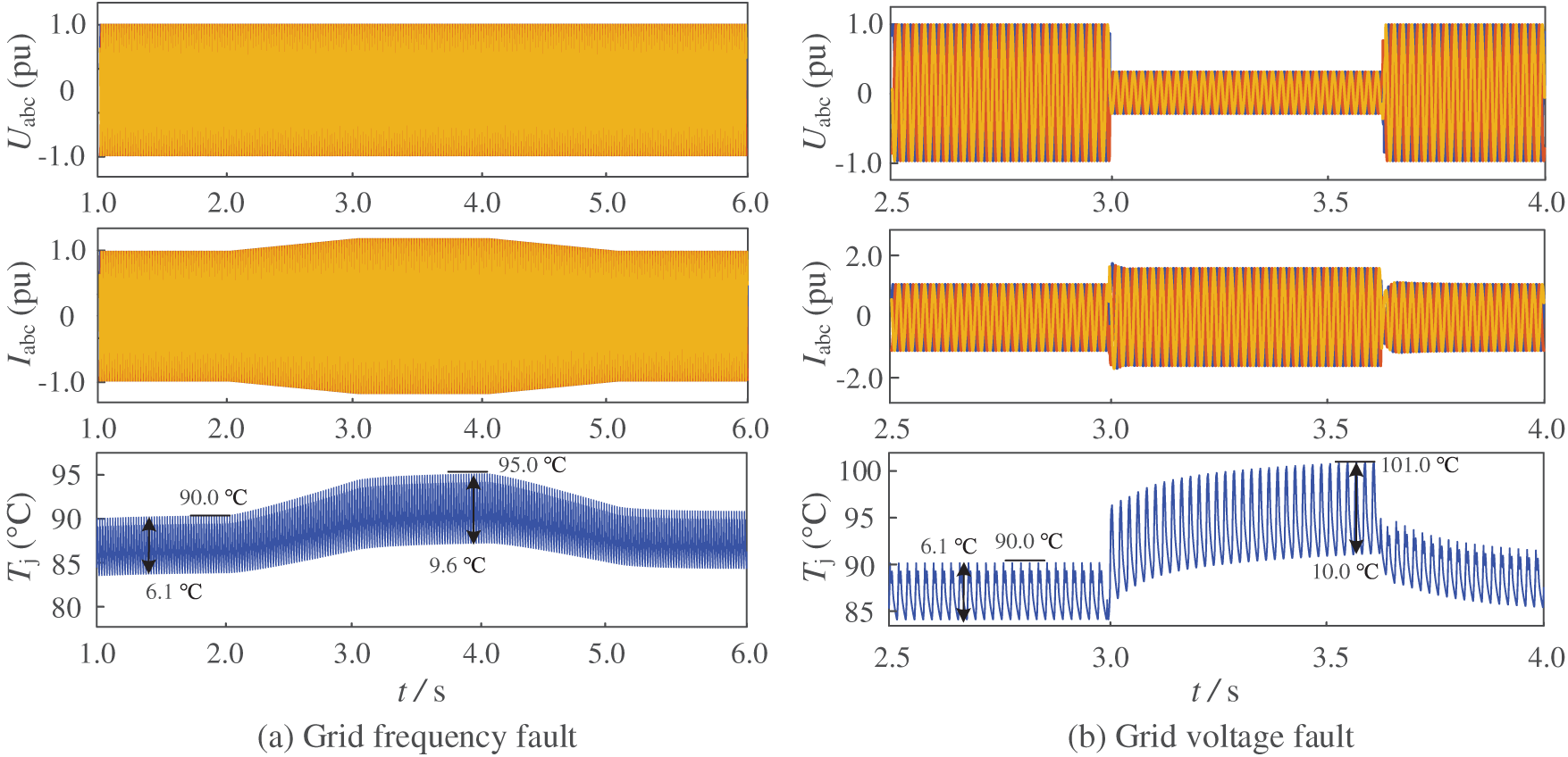
Figure 9: Simulation results of the wind power converter under grid transient faults without the proposed ATC strategy.
From Fig. 9a, it can be seen that before the disturbance, the wind power converter outputs 1.0 p.u. current under the rated operating condition, where the junction temperature exhibits a maximum of 90.0°C, an average of 87°C, and a thermal swing of 6.1°C. When the grid frequency starts to drop at t = 2.0 s, the converter increases its active power injection to provide inertial support. At t = 3.0 s, the frequency reaches 49 Hz (0.98 p.u.), and the output current rises to 1.2 p.u. The corresponding maximum junction temperature increases to 95°C, the average junction temperature rises to 90.2°C, and the thermal swing expands to 9.6°C. According to the lifetime model given in Eq. (11), such enhanced thermal stress leads to a significant degradation of power semiconductor lifetime. As the frequency starts to recover at t = 4.0 s, the thermal stress gradually decreases. Meanwhile, for the low-voltage fault scenario in Fig. 9b, the pre-fault thermal stress remains consistent, with the maximum junction temperature of 90.0°C, average temperature of 87°C, and thermal swing of 6.1°C, validating the accuracy of the developed electro-thermal model. When the PCC voltage drops to 0.2 p.u. at t = 3.0 s, the converter output current jumps to 1.5 p.u., reaching the maximum current limit. Due to the thermal inertia, the junction temperature does not change instantly but rises progressively, reaching 95.2°C at the initial instant of the voltage dip and further increasing to 101°C at t = 3.625 s. Meanwhile, the average junction temperature reaches 96.0°C, and the thermal swing increases to 10°C. Therefore, compared with the frequency drop case, a voltage dip event induces more severe transient over-current stress and junction temperature rise, which significantly accelerates device aging and reduces lifetime.
With the proposed ATC strategy enabled, the simulation results under the frequency-drop and voltage-dip scenarios are shown in Fig. 10a,b, respectively, while all parameters remain identical to those in Table 2. As illustrated in Fig. 10a, due to the activation of the ATC strategy, when the grid frequency drops and the converter current increases, the switching frequency starts to decrease once the junction temperature exceeds the predefined limit of 90°C at t = 3.0 s. As a result, the peak junction temperature is reduced from 95°C (without ATC) to 91°C, and the thermal swing is reduced from 9.6°C to 6.5°C, which is comparable to the pre-fault operating condition. The average junction temperature is also reduced from 90.2°C to 88.2°C. For the low-voltage fault in Fig. 10b, the maximum junction temperature at the moment of fault clearance (t = 3.625 s) is reduced from 101°C to 96.8°C with ATC enabled. Meanwhile, the thermal swing drops from 10.0°C to 7.1°C, and the average temperature decreases from 96.0°C to 93.3°C. These results indicate that by dynamically lowering the switching frequency according to the junction temperature evolution, the proposed ATC strategy effectively suppresses thermal overstress during transient grid faults. Consequently, the converter can operate with lower switching losses and reduced thermal stress, thereby improving the predicted device lifetime.
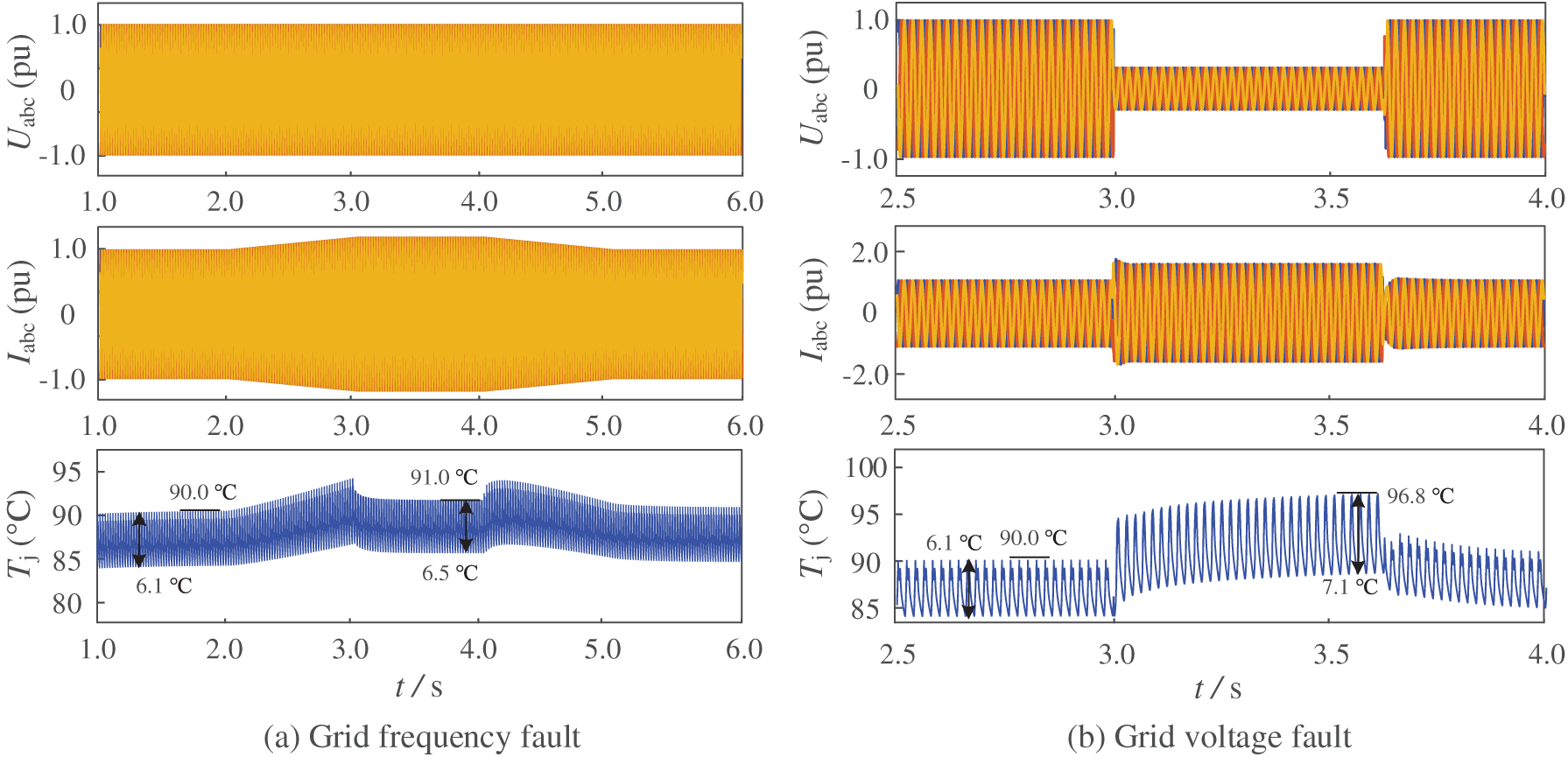
Figure 10: Simulation results of the wind power converter under grid transient faults with the proposed ATC strategy.
Finally, the variations in the predicted lifetime of the wind power converter with and without the proposed ATC strategy under two types of transient grid faults are shown in Fig. 11a,b. It can be observed that under normal operating conditions, the expected failure cycles Nf is approximately 1.1 × 10⁷. When the grid frequency drops and the output current rises, Nf decreases to 0.97 × 10⁷. With the proposed ATC applied, Nf only decreases to 1.06 × 10⁷, indicating that the lifetime degradation is reduced by approximately 54% compared with the case without ATC. For the low-voltage fault scenario shown in Fig. 9b, Nf drops to 1.01 × 10⁷ without ATC, whereas with the proposed strategy it increases to 1.08 × 10⁷, corresponding to a reduction of about 78% in lifetime degradation. These results clearly demonstrate that the proposed ATC approach effectively mitigates the lifetime reduction risk of wind power converters under transient grid fault conditions. It should be noted that the lifetime variation is evaluated in terms of expected failure cycles associated with short-duration grid transient events, rather than absolute calendar lifetime, which would require long-term mission profile assumptions beyond the scope of this study.
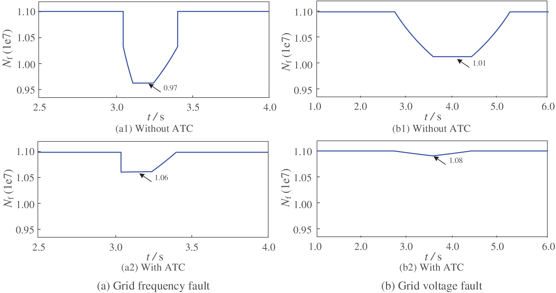
Figure 11: Expected lifetime variation of the wind power converter during grid transient faults, comparing cases with and without the proposed ATC strategy.
The electrothermal stress imposed on power semiconductor devices in wind turbine converters critically affects their reliability and operational lifetime. However, most existing studies focus only on long-term operating conditions, while the impact of short-term overstress caused by power grid transient faults has been largely overlooked. To address this issue, this paper first establishes a multi-physics coupled analytical model that incorporates the converter control, power loss evaluation, and junction temperature calculation. A lifetime estimation approach is then developed based on this model. Furthermore, the feasibility of mitigating junction-temperature excursions within the transient duration of grid faults is analyzed, and an ATC strategy based on dynamic switching-frequency adjustment is proposed. When the junction temperature exceeds a predefined threshold, the switching frequency is reduced to suppress the rise of both the temperature mean value and thermal cycling amplitude, thereby alleviating lifetime degradation under fault conditions. Finally, case studies on grid frequency disturbance and low-voltage fault events are conducted in PLECS. Simulation results show that the proposed ATC strategy can reduce the junction-temperature mean value by approximately 2.0°C and 2.7°C and the thermal cycling amplitude by 1.1°C and 2.9°C under the two fault scenarios, respectively, leading to a reduction of lifetime deterioration by about 54% and 78%. These results confirm the effectiveness of the proposed approach in enhancing converter reliability during transient grid faults. Future research could extend the proposed ATC strategy to other types of converters, such as photovoltaic and energy storage systems, and explore the applicability of grid-forming control. Additionally, the method can be further validated under various grid fault conditions to assess its performance in real-world applications.
Acknowledgement: Not applicable.
Funding Statement: This research was funded by National Key R&D Program of China, key technologies for coordinated optimization and control of deep-sea offshore wind farm clusters, grant number 2023YFB4203200.
Author Contributions: The authors confirm contribution to the paper as follows: Conceptualization, Yihua Zhu, Chao Luo and Yuxia Tang; methodology, Yihua Zhu, Yuxia Tang and Renxin Yang; software, Yihua Zhu; validation, Yihua Zhu, Chao Luo and Yuxia Tang; formal analysis, Yihua Zhu and Yuxia Tang; investigation, Yihua Zhu, Chao Luo and Yuxia Tang; data curation, Yihua Zhu; writing—original draft preparation, Yihua Zhu; writing—review and editing, Chao Luo, Yuxia Tang and Renxin Yang; visualization, Yihua Zhu; supervision, Renxin Yang; project administration and funding acquisition, Yihua Zhu, Chao Luo and Yuxia Tang. All authors reviewed and approved the final version of the manuscript.
Availability of Data and Materials: Not applicable.
Ethics Approval: Not applicable.
Conflicts of Interest: The authors declare no conflicts of interest.
Nomenclature
| ATC | Active thermal control |
| LVRT | Low voltage ride through |
| SPWM | Sinusoidal pulse width modulation |
| SVPWM | Space vector pulse width modulation |
| FRT | Fault ride through |
| PMSG | Permanent magnet synchronous generator |
| MSC | Machine-side converter |
| GSC | Grid-side converter |
| PLL | Phase-locked loop |
| MPPT | Maximum power point tracking |
| IGBT | Insulated gate bipolar transistor |
| Tj | Junction temperature |
| Tn | Temperature threshold for ATC activation |
| Tc | Case temperature |
| Zth | Thermal impedance |
| Rth | Thermal resistance |
| Cth | Thermal capacitance |
| fsw | Switching frequency |
| f0 | Nominal switching frequency |
| K6 | Proportional coefficient for switching-frequency adjustment |
| K7 | Hysteresis coefficient |
| Ploss | Power loss |
| Psw | Switching loss |
| Pcond | Conduction loss |
| Pref | Reference active power |
| Pm | Power of MSC |
| isdq | d/q-axis output currents of MSC |
| isdqref | d/q-axis current references of MSC |
| idq | d/q-axis grid currents of GSC |
| idqref | d/q-axis current references of GSC |
| usdq | d/q-axis modulation voltages of MSC |
| udq | d/q-axis modulation voltages of GSC |
| Kpi | PI gains of power controller |
| Kspi | PI gains of the MSC current controller |
| Kpi | PI gains of the GSC current controller |
| Kin | Inertia response coefficient |
| wg | Grid angular frequency |
| Lr | Stator-side inductance |
| Lf | Filter inductance |
| Sr | Switching signals of MSC |
| Sg | Switching signals of GSC |
| Nf | Number of cycles to failure |
References
1. Abe R, Taoka H, McQuilkin D. Digital grid: communicative electrical grids of the future. IEEE Trans Smart Grid. 2011;2(2):399–410. doi:10.1109/TSG.2011.2132744. [Google Scholar] [CrossRef]
2. Rocabert J, Luna A, Blaabjerg F, Rodríguez P. Control of power converters in AC microgrids. IEEE Trans Power Electron. 2012;27(11):4734–49. doi:10.1109/TPEL.2012.2199334. [Google Scholar] [CrossRef]
3. Guerrero JM, de Vicuna LG, Matas J, Castilla M, Miret J. A wireless controller to enhance dynamic performance of parallel inverters in distributed generation systems. IEEE Trans Power Electron. 2004;19(5):1205–13. doi:10.1109/TPEL.2004.833451. [Google Scholar] [CrossRef]
4. Ali SH, Heydarzadeh M, Dusmez S, Li X, Kamath AS, Akin B. Lifetime estimation of discrete IGBT devices based on Gaussian process. IEEE Trans Ind Appl. 2018;54(1):395–403. doi:10.1109/TIA.2017.2753722. [Google Scholar] [CrossRef]
5. Zhou R, An T, Qin F. Lifetime prediction method for IGBT modules under combined power cycling–vibration conditions. IEEE Trans Device Mater Reliab. 2025;25(3):714–22. doi:10.1109/TDMR.2025.3592624. [Google Scholar] [CrossRef]
6. Lu Y, Xiang E, Zhu L, Gao H, Yang H, Zhao R. Mission profile-based lifetime estimation and its system-controlled improvement method of IGBT modules for electric vehicle converters. CPSS Trans Power Electron Appl. 2023;8(3):246–56. doi:10.24295/CPSSTPEA.2023.00023. [Google Scholar] [CrossRef]
7. Kuprat J, van der Broeck CH, Andresen M, Kalker S, Liserre M, De Doncker RW. Research on active thermal control: actual status and future trends. IEEE J Emerg Sel Top Power Electron. 2021;9(6):6494–506. doi:10.1109/JESTPE.2021.3067782. [Google Scholar] [CrossRef]
8. Wang A, Qi Y, Ma K. Adaptive DC voltage control for optimal junction temperature redistribution under stall condition of electric machine drive inverter. IEEE Trans Power Electron. 2023;38(4):4229–34. doi:10.1109/TPEL.2022.3231867. [Google Scholar] [CrossRef]
9. Prasobhu PK, Buticchi G, Brueske S, Liserre M. Gate driver for the active thermal control of a DC/DC GaN-based converter. In: Proceedings of the 2016 IEEE Energy Conversion Congress and Exposition (ECCE); 2016 Sep 18–22; Milwaukee, WI, USA. p. 1–8. doi:10.1109/ECCE.2016.7855131. [Google Scholar] [CrossRef]
10. Du X, Li G, Sun P, Zhou L, Tai HM. A hybrid modulation method for lifetime extension of power semiconductors in wind power converters. In: Proceedings of the 2015 IEEE Applied Power Electronics Conference and Exposition (APEC); 2015 Mar 15–19; Charlotte, NC, USA; 2015. p. 2565–70. doi:10.1109/APEC.2015.7104712. [Google Scholar] [CrossRef]
11. Falck J, Andresen M, Liserre M. Active thermal control of IGBT power electronic converters. In: Proceedings of the IECON 2015—41st Annual Conference of the IEEE Industrial Electronics Society; 2015 Nov 9–12; Yokohama, Japan. p. 1–6. doi:10.1109/IECON.2015.7392925. [Google Scholar] [CrossRef]
12. Ibrahim A, Salem M, Kamarol M, Delgado MT, Desa MKM. Review of active thermal control for power electronics: potentials, limitations, and future trends. IEEE Open J Power Electron. 2024;5:414–35. doi:10.1109/ojpel.2024.3376086. [Google Scholar] [CrossRef]
13. Xia S, Ma K, Qi Y, Cai X, Zheng L, Li X, et al. Bandwidth enhancement of electric machine emulator with virtual-impedance control. IEEE Trans Power Electron. 2024;39(12):15609–21. doi:10.1109/TPEL.2024.3443919. [Google Scholar] [CrossRef]
14. Musarrat MN, Islam MR, Muttaqi K, Sutanto D, Rahman MA. Improving the thermal performance of rotor-side converter of doubly fed induction generator wind turbine while operating around synchronous speed. IEEE J Emerg Sel Top Ind Electron. 2022;3(2):298–307. doi:10.1109/JESTIE.2021.3122996. [Google Scholar] [CrossRef]
15. Cao Y, Peng Y, Zhao C, Wang Q, Shuai Z. Active thermal control with switching frequency modulation for fundamental frequency junction temperature of the VSG. IEEE J Emerg Sel Top Power Electron. 2025;13(1):531–41. doi:10.1109/JESTPE.2024.3476158. [Google Scholar] [CrossRef]
16. Lemmens J, Vanassche P, Driesen J. Optimal control of traction motor drives under electrothermal constraints. IEEE J Emerg Sel Top Power Electron. 2014;2(2):249–63. doi:10.1109/JESTPE.2014.2299765. [Google Scholar] [CrossRef]
17. Ma K, Blaabjerg F. Modulation methods for neutral-point-clamped wind power converter achieving loss and thermal redistribution under low-voltage ride-through. IEEE Trans Ind Electron. 2014;61(2):835–45. doi:10.1109/TIE.2013.2254099. [Google Scholar] [CrossRef]
18. Mayilsamy G, Lee SR, Joo YH. Open-switch fault diagnosis in back-to-back NPC converters of PMSG-based WTS via zero range value of phase currents. IEEE Trans Power Electron. 2024;39(4):4687–703. doi:10.1109/TPEL.2023.3347563. [Google Scholar] [CrossRef]
19. Nejadpak A, Mirafzal B, Mohammed O, Wei L. Effects of different switching algorithms on the thermal behavior of IGBT modules under pulse-load conditions. In: Proceedings of the IECON 2010—36th Annual Conference on IEEE Industrial Electronics Society; 2010 Nov 7–10; Glendale, AZ, USA. p. 451–6. doi:10.1109/IECON.2010.5674984. [Google Scholar] [CrossRef]
20. Deng Y, Li J, Shin KH, Viitanen T, Saeedifard M, Harley RG. Improved modulation scheme for loss balancing of three-level active NPC converters. IEEE Trans Power Electron. 2017;32(4):2521–32. doi:10.1109/TPEL.2016.2573823. [Google Scholar] [CrossRef]
21. Arani MFM, Mohamed YAI. Assessment and enhancement of a full-scale PMSG-based wind power generator performance under faults. IEEE Trans Energy Convers. 2016;31(2):728–39. doi:10.1109/TEC.2016.2526618. [Google Scholar] [CrossRef]
22. Isidori A, Rossi FM, Blaabjerg F, Ma K. Thermal loading and reliability of 10-MW multilevel wind power converter at different wind roughness classes. IEEE Trans Ind Appl. 2014;50(1):484–94. doi:10.1109/TIA.2013.2269311. [Google Scholar] [CrossRef]
23. Yu X, Hu B, Xie K, Shao C, Bai Y, Li W, et al. Reliability evaluation of wind power converter under fault-tolerant control scheme with quantification of temperature and humidity effects. J Mod Power Syst Clean Energy. 2023;11(5):1700–10. doi:10.35833/MPCE.2022.000228. [Google Scholar] [CrossRef]
24. Hu Q, Ji F, Ma F, Zhang Y, Fu L. Matching analysis of LVRT grid code and injection current dependent voltage response of WTC connected to high impedance AC grid. IEEE Trans Energy Convers. 2022;37(3):2236–9. doi:10.1109/TEC.2022.3169394. [Google Scholar] [CrossRef]
25. Hu Z, Cui M, Wu X. Real-time temperature prediction of power devices using an improved thermal equivalent circuit model and application in power electronics. Micromachines. 2023;15(1):63. doi:10.3390/mi15010063. [Google Scholar] [PubMed] [CrossRef]
26. Sangwongwanich A, Wang H, Blaabjerg F. Reduced-order thermal modeling for photovoltaic inverters considering mission profile dynamics. IEEE Open J Power Electron. 2020;1:407–19. doi:10.1109/OJPEL.2020.3025632. [Google Scholar] [CrossRef]
27. Xiao X, Ge X, Ke Q, Yong L, Liao Y, Wang H, et al. An adaptive temperature observer for electrothermal analysis of IGBT based on temperature characteristics. IEEE J Emerg Sel Topics Power Electron. 2023;11(2):2246–58. doi:10.1109/jestpe.2022.3231718. [Google Scholar] [CrossRef]
28. Abuelnaga A, Narimani M, Bahman AS. A review on IGBT module failure modes and lifetime testing. IEEE Access. 2021;9:9643–63. doi:10.1109/ACCESS.2021.3049738. [Google Scholar] [CrossRef]
Cite This Article
 Copyright © 2026 The Author(s). Published by Tech Science Press.
This work is licensed under a Creative Commons Attribution 4.0 International License , which permits unrestricted use, distribution, and reproduction in any medium, provided the original work is properly cited.
 Downloads
 Citation Tools
