
 Login
Login Register
 Submit a Paper
 Propose a Special lssue
 Open Access
ARTICLE
A Low-High Voltage Continuous Ride-Through Control Strategy for Permanent Magnet Wind Turbines Based on Rotor Kinetic Energy
1 Key Laboratory of Modern Power System Simulation and Control & Renewable Energy Technology, Ministry of Education (Northeast Electric Power University), Jilin, China
2 State Grid Jilin Electric Power Company Limited Changchun Power Supply Company, Changchun, China
* Corresponding Author: Xiaye Wang. Email:
Energy Engineering 2026, 123(11), 5 https://doi.org/10.32604/ee.2026.078180
Received 25 December 2025; Accepted 11 March 2026; Issue published 24 September 2026
 View Full Text
 Download PDF
Abstract
With the large-scale integration of wind turbines into power systems, the voltage at the grid connection point exhibits continuous oscillation characteristics, which significantly increases the ride-through difficulty and off-grid risk of wind turbines during faults. To address the above problems, this paper proposes a low-high voltage ride-through (L-HVRT) control strategy based on rotor energy storage. This strategy reduces the load on the unloading resistor by decreasing the active power output from the machine-side converter (MSC). To prevent overspeed disconnection during this process, an active power reference value for the MSC output is preset to proactively suppress rotor overspeed, thereby preventing the permanent magnet synchronous generator (PMSG) speed from exceeding the safety limit. Based on the PSCAD simulation platform, a corresponding simulation model is established to verify the feasibility of the proposed control strategy. The simulation results show that the strategy can effectively improve the continuous fault ride-through capability of wind turbines.Keywords
With the increasing severity of environmental pollution and climate change, the penetration level of wind power has continued to rise [1]. To ensure the stable operation of power systems with large-scale wind power integration, wind turbines are required not only to possess low-voltage ride-through (LVRT) capability [2] and high-voltage ride-through (HVRT) capability [3], but also to withstand consecutive low- and high-voltage disturbances, namely low–high voltage ride-through (L-HVRT) capability [4].
Currently, extensive research exists regarding LVRT and HVRT. To enhance the ride-through capability of wind turbines during faults, existing solutions generally fall into two main categories: hardware-based improvements and control strategy optimizations.
Regarding hardware-based improvements, research focus typically lies in introducing additional auxiliary physical devices to balance system power or suppress fault currents. Specifically, Ref. [5] proposed utilizing the rapid power throughput characteristics of superconducting magnetic energy storage systems to absorb unbalanced energy during faults. Refs. [6,7] explored the application of superconducting fault current limiters in restricting short-circuit current impacts and protecting converters. Furthermore, Ref. [8] investigated the role of supercapacitor energy storage systems in smoothing DC bus voltage fluctuations. Additionally, installing a dynamic braking resistor on the DC side of the converter is a common hardware solution [9], which maintains system stability by dissipating excess active power as thermal energy. Although these hardware-based schemes can significantly improve the LVRT and HVRT performance of the units, they are often accompanied by high equipment investment costs, large physical footprints, and complex operation and maintenance requirements. These economic and engineering implementation limitations have, to some extent, hindered their large-scale promotion and application in cost-sensitive commercial wind farms.
To overcome the limitations of hardware-based solutions regarding cost and engineering implementation, optimizing converter control strategies for fault ride-through has increasingly become the mainstream of research in both academia and industry. These methods aim to maintain system stability by utilizing the converter’s inherent regulatory capabilities without incurring additional hardware costs. For LVRT conditions, Refs. [10,11] proposed strategies based on flux-weakening control to suppress the surge in DC bus voltage by adjusting stator current components, while Refs. [12,13] achieved rapid balance between input and output power by directly regulating the machine-side electromagnetic torque. Regarding HVRT conditions, Refs. [14,15] proposed a GSC-based reactive power priority control strategy, utilizing the absorption of inductive reactive power to assist in grid voltage recovery. However, most of the aforementioned control strategies focus on addressing single voltage-dip or voltage-swell faults. When facing the complex conditions of L-HVRT, relying solely on machine-side torque regulation can easily lead to severe rotor speed fluctuations due to power imbalance, while relying only on grid-side reactive power regulation is often limited by the converter’s current capacity, making it difficult to simultaneously ensure DC-side overvoltage protection and rotor speed stability.
Currently, research on the L-HVRT of wind turbines in complex grid environments is gradually unfolding. To address system stability issues during continuous faults, scholars have proposed various improvement schemes from different perspectives.
Regarding control strategy optimization, Reference [16] introduced virtual synchronous generator (VSG) technology, which enhances the system’s frequency and voltage support capabilities under continuous voltage disturbances by simulating the inertia and damping characteristics of synchronous generators. Ref. [17], addressing the limitations of a fixed reactive current proportional coefficient K, proposed a variable K value control strategy to avoid insufficient or excessive reactive power support during slight voltage dips or recovery stages.
In terms of hardware assistance, Ref. [18] explored the use of supercapacitor energy storage systems to cope with faults, smoothing DC bus voltage fluctuations through an adaptive coordinated control strategy and assisting in grid voltage recovery.
Additionally, Research on L–HVRT remains limited. Ref. [19] proposes an L–HVRT control strategy based on a braking resistor and dynamic reactive power support, in which the voltage operating range is dynamically partitioned according to different voltage sag and swell conditions during grid faults, and the corresponding reactive current references are accordingly assigned. In addition, a braking resistor is connected in parallel with the DC link to dissipate the active power imbalance ΔP between the MSC and the GSC.
For convenience of discussion, the control strategy proposed in [19] is hereinafter referred to as the conventional control strategy. This conventional strategy imposes stringent requirements on the braking resistor, and when the active power imbalance ΔP becomes large, it may result in the failure of the braking resistor.
The paper addresses the limitations of conventional L-HVRT control strategies by proposing a rotor-based energy storage control strategy for permanent magnet wind turbines. By exploiting the kinetic energy stored in the PMSG rotor, the active power imbalance ΔP is effectively reduced, thereby alleviating the burden on the braking resistor. Simulations are carried out in PSCAD/EMTDC based on the technical parameters of an in-service PMSG-based wind farm, where a continuous fault ride-through model of the wind turbine is established to verify the effectiveness of the proposed control strategy.
2 Analysis of the Conventional Control Strategy
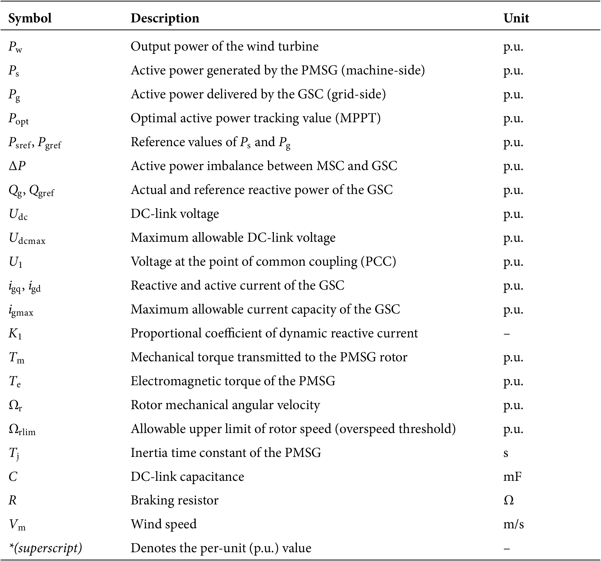
The grid-connected configuration of the PMSG-based wind turbine is illustrated in Fig. 1. In the figure, Pw denotes the output power of the wind turbine; Ps represents the active power generated by the PMSG; Pg is the active power delivered by the GSC; ΔP = Ps − Pg denotes the active power imbalance between the GSC and the MSC; C is the DC-link capacitor; Udc represents the DC-link voltage; R denotes the braking resistor; R1 and R2 are the line resistances; and X1 and X2 are the line reactances.
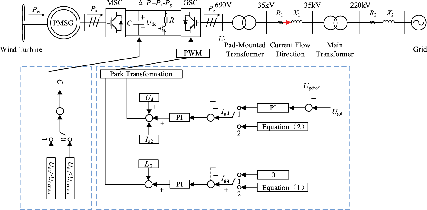
Figure 1: Grid-connected system structure and control diagram of a pmsg-based wind turbine under the conventional control strategy.
Under normal operating conditions, the wind turbine operates in the maximum power point tracking (MPPT) mode, where Pw = Ps = Pg = Popt. The DC-link voltage Udc is maintained at its reference value. This section analyzes the conventional control strategy during the L–HVRT process.
During L-HVRT, according to [19], the reference value of reactive current injected by the wind turbine into the power system, igqref is given by:
In the formula: K1 is the proportional coefficient of the wind farm’s dynamic reactive current; U1 is the voltage at the point of common coupling (PCC); * denotes per-unit value.
To prevent overcurrent of the GSC, the reference value of active current of the GSC, igdref is given by:
In the formula: igmax is the maximum allowable current through the GSC.
According to Eqs. (1) and (2) and Ref. [19], the reactive power reference value Qgref and active power reference value Pgref output by the GSC during the L-HVRT period are given by:
Specifically, a strong physical coupling exists between the reactive current iq and the active current id. During HVRT, the GSC is required by grid codes to inject a substantial amount of inductive reactive current iq to suppress PCC voltage swells. Given that the converter’s total current capacity igmax is fixed (constrained by the thermal limits of power electronic devices), and subject to the constraint (igd)2 + (igq)2 ≤ (igmax)2, a significant increase in iq inevitably reduces the available margin for active current id. This saturation of active current directly restricts the GSC’s capability to export active power Pg to the grid, thereby exacerbating the power imbalance ΔP between the machine-side input and the grid-side output. Consequently, employing effective energy dissipation or transfer strategies—such as activating dynamic braking resistors or leveraging rotor kinetic energy storage—becomes critical.
During the L-HVRT period, under the traditional control strategy, according to Ref. [19], Psref = Popt.
In traditional control strategies, the machine-side active power Ps is maintained at the maximum power point (MPPT) value Popt without dynamic curtailment, despite the reduction in grid-side power export capability. This is attributed to the large mechanical inertia of the pitch system, which prevents a rapid reduction of the mechanical torque Tm at the instant of fault inception. If Ps were drastically reduced (i.e., reducing the electromagnetic torque Te) to mitigate ΔP, it would cause a severe torque imbalance (Tm >> Te), driving the rotor to accelerate rapidly and triggering overspeed tripping. Consequently, the traditional strategy adopts a logic of “maintaining machine-side power while relying on resistive energy dissipation,” which essentially prioritizes rotor speed stability at the expense of increased thermal stress on the braking resistor.
During the L-HVRT period, due to the limitations of the GSC capacity during LVRT and the grid power backfeed during HVRT [20], the power balance between Ps and Pg is disrupted, resulting in ΔP > 0. This causes the DC-link voltage Udc to rise, and may even damage the DC-side components. It is necessary to connect the braking resistor R to dissipate ΔP. The switching scheme of the braking resistor R is as follows:
(1) When Udc > the maximum allowable DC-link voltage Udcmax, the braking resistor is connected to dissipate ΔP;
(2) When Udc < Udcmax, the braking resistor is disconnected from operation.
In summary, during the L-HVRT period, under the traditional control strategy, setting Psref = Popt results in a large ΔP, which imposes a heavy burden on the braking resistor R and may even lead to its failure.
3 L–HVRT Control Scheme Based on Rotor Energy Storage
According to the analysis in Section 1, the active power imbalance ΔP should be reduced to prevent the failure of the braking resistor. As indicated by ΔP = Ps − Pg, a reduction in Ps leads to a decrease in ΔP.
The rotor motion equation of the PMSG is expressed as:
In the formula: d/dt is the differential operator; Ω1 is the rated rotor angular velocity of the PMSG; Ωr is the rotor angular velocity of the PMSG; Tm is the mechanical torque transmitted from the wind turbine to the PMSG rotor; Te is the electromagnetic torque of the PMSG, with Te* = Ps*/Ωr*; Tj is the inertia time constant of the PMSG.
Reducing Ps will decrease Te. According to Eq. (4), a decrease in Te will cause Ωr to increase, and in severe cases, Ωr will exceed the limit [16].
Therefore, this section proposes an L-HVRT control strategy based on rotor energy storage. By setting a reasonable Ps, both the reduction of ΔP and the suppression of rotor speed over-limit are achieved. The control strategy proposed in this paper is as follows.
Under the control strategy proposed in this paper, the Qgref and Pgref output by the GSC are the same as those under the traditional control strategy, as shown in Eq. (3).
The tuning of Ps is based on the following assumptions: (1) The voltage phase changes caused by voltage sags and swells are neglected; (2) Tm remains unchanged before and after voltage sags and swells; (3) The most severe scenario is considered, where the HVRT phase starts immediately after the end of LVRT; (4) n times of L-HVRT are performed, with the same duration for each L-HVRT, the same LVRT duration within each L-HVRT, and the same HVRT duration within each L-HVRT.
The n times of L-HVRT are illustrated in Fig. 2. Let t0 be the start time of the 1st L-HVRT, and ti (i = 1, 2, … , n) be the end time of the i-th L-HVRT. T(i−1)~i is the end time of the i-th LVRT and also the start time of the i-th HVRT.

Figure 2: Schematic diagram of the -time L-HVRT process.
In the figure: PsLi is the active power output by the MSC during the LVRT phase of the i-th L-HVRT; PsHi is the active power output by the MSC during the HVRT phase of the i-th L-HVRT. ΔtLi is the duration of the i-th LVRT; ΔtHi is the duration of the i-th HVRT.
To ensure that the rotor speed Ωr remains within the safe range throughout the entire fault ride-through period, it is necessary to inversely solve for the minimum active power allowed for the MSC output. Based on Eq. (4), we integrate the acceleration torque during the fault period over time:
In the figure: Ωr(ti) is the rotor mechanical angular velocity at t = ti, and u is the integration variable.
According to Eq. (5), integrating both sides simultaneously yields:
During the L-HVRT period, Ωr shall satisfy Ωr ≤ the allowable upper limit of rotor speed Ωrlim. Furthermore, according to Eq. (6), it can be derived that:
During the L-HVRT period, the allowable increment of Ωr is ΔΩ = Ωrlim–Ωr(t0). Based on the durations of LVRT and HVRT in each L-HVRT, this paper tunes Psref for the n-time L-HVRT period.
During the L-HVRT period, the increment of Ωr is taken as:
In the figure: ΔΩLi is the increment of Ωr at the end of LVRT during the i-th L-HVRT; ΔΩHi is the increment of Ωr at the end of HVRT during the i-th L-HVRT.
Substituting Eq. (8) into Eq. (7) yields:
From Eq. (9), it can be obtained that PsLi = PsHi. Consequently, the active power reference Psref output by the MSC during the L-HVRT period is set as:
In the figure: Psmin is the minimum active power output by the MSC.
In practical implementation, this control strategy relies on real-time online calculations. The controller continuously monitors the PCC voltage U1; upon detecting a voltage sag or swell, the system retrieves the most stringent ride-through duration requirements corresponding to the current voltage depth from a grid-code-based look-up table. By substituting these standardized parameters—rather than uncertain actual fault durations—into Eq. (10), the safety-critical reference Psref is determined. This “worst-case design” approach guarantees that the rotor speed remains within safe limits for any fault duration complying with grid standards.
To prevent control interactions during severe voltage faults, the strategy employs an explicit decoupled control architecture. The GSC prioritizes reactive power injection to comply with grid codes, rendering its active power export capability Pg a passive variable. To isolate Pg fluctuations from MSC stability, the braking resistor serves as a critical decoupling unit. By rapidly switching the resistor to stabilize Udc, effective dynamic isolation is achieved between the MSC’s active power loop and the GSC’s reactive power loop. This coordination ensures that the MSC can independently regulate Ps via Eq. (10) without compensating for GSC dynamics, thereby guaranteeing overall system stability.
Notably, during deep voltage faults, the “reactive power priority” principle often drives the GSC into current saturation, constraining its active current igd to near-zero levels. This grid-side saturation does not hinder the effectiveness of the MSC’s active power control. Conversely, since the GSC is virtually unable to export active power (Pg ≈ 0), the MSC’s active power curtailment strategy based on Eq. (10) becomes critical. This machine-side “active power reshaping” mechanism operates independently of the GSC state, mitigating the risk of power surplus accumulation at the source caused by GSC saturation. Consequently, it effectively prevents resistor overloading and ensures safe ride-through under extreme fault conditions.
When the control strategy proposed in this paper is adopted, if ΔP > 0, the braking resistor R still needs to be connected. The switching scheme of the braking resistor R is the same as that of the traditional control strategy.
In summary, the control block diagrams of the MSC and GSC under the control strategy proposed in this paper are shown in Figs. 3 and 4, respectively, and the flow chart of the control strategy is shown in Fig. 5.
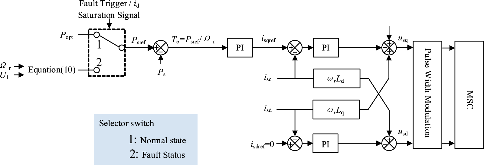
Figure 3: Control block diagram of the MSC for the control strategy proposed in this paper.
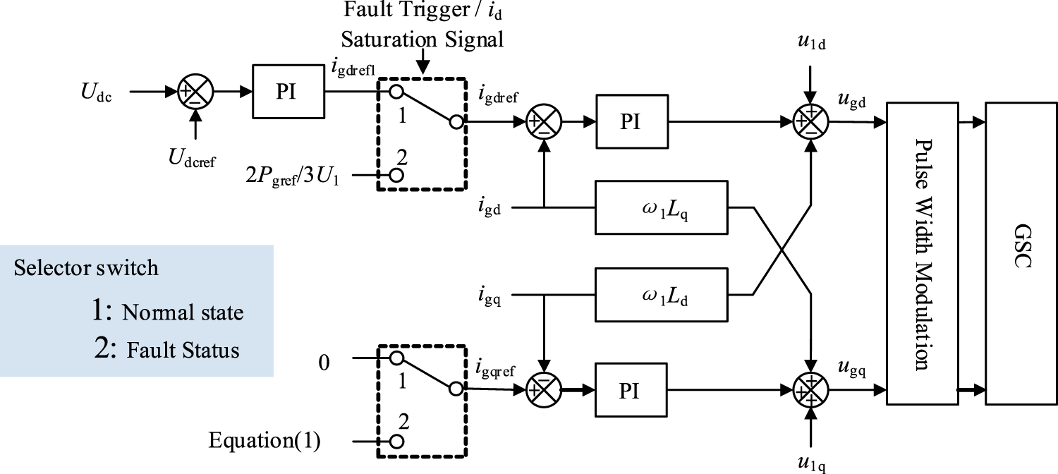
Figure 4: Control block diagram of the GSC for the control strategy proposed in this paper.
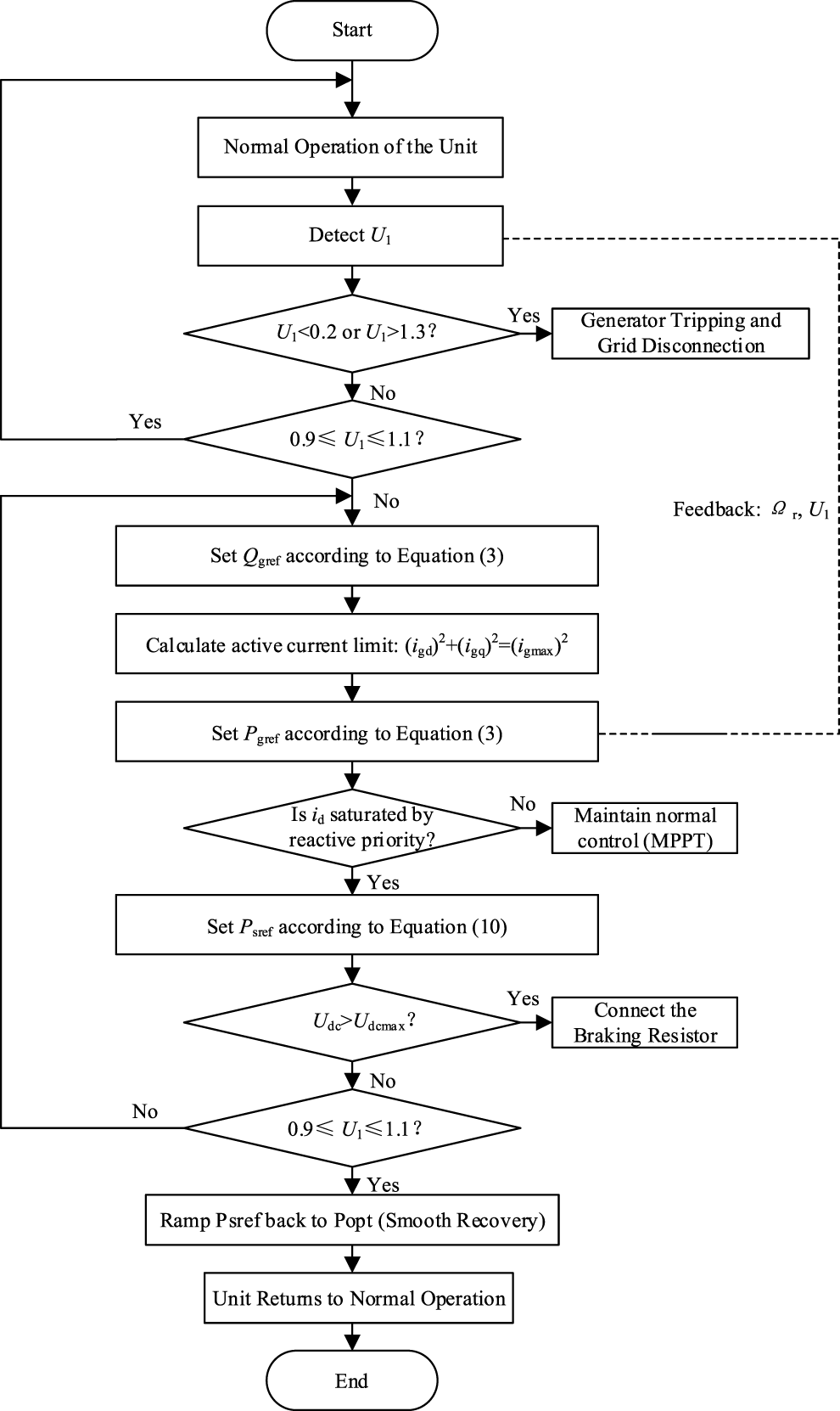
Figure 5: Flow chart of the control strategy proposed in this paper.
3.4 Comparative Analysis of Control Strategies
Eq. (10) constitutes the core contribution of this work, as it mathematically defines the optimal trade-off between “braking resistor load” and “rotor speed safety.” To illustrate the superiority of the proposed strategy in resolving this conflict, Table 1 presents a comprehensive performance comparison between the proposed method and two typical existing strategies: the traditional strategy [19] and the power balance strategy (Ps = Pg).
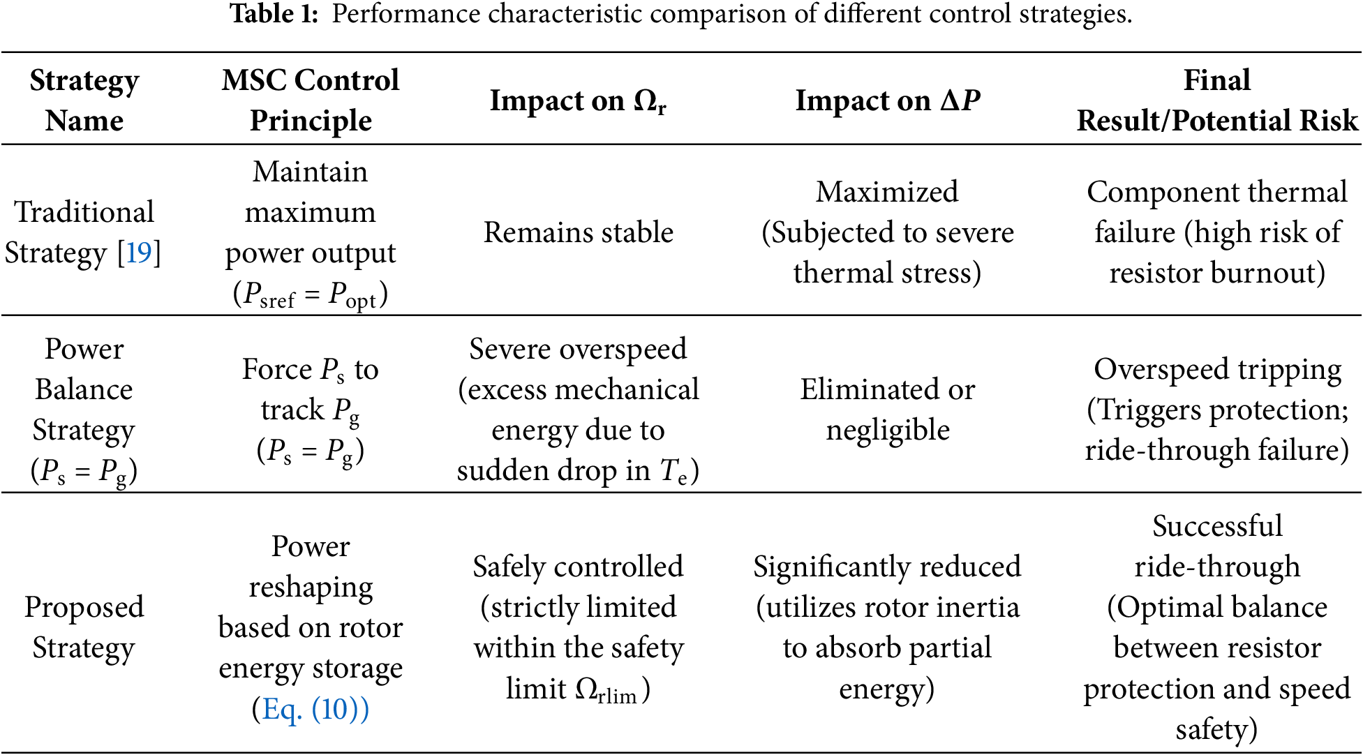
As detailed in Table 1, while the traditional strategy maintains rotor speed stability, it does so at the expense of sustaining high power output for extended periods. This results in extreme thermal stress on the braking resistor (ΔP maximization), significantly increasing the risk of component burnout. Conversely, the power balance strategy eliminates the thermal burden on the resistor by enforcing a reduction in machine-side power to match the grid side. However, this approach neglects the sustained mechanical torque input, causing rapid, uncontrolled rotor acceleration during faults, which ultimately leads to tripping due to overspeed protection.
In contrast, the strategy proposed in this paper effectively reconciles this conflict. By accurately calculating the maximum kinetic energy the rotor can absorb, the strategy achieves optimized active power reshaping. It avoids excessive resistor utilization while strictly confining the rotor speed within the safety limit Ωrlim, thereby providing an optimal compromise for safe L-HVRT operation.
3.5 Mechanical Constraints and Control Stability
3.5.1 Mechanical Constraints and Shaft Stress Analysis
During L-HVRT, modulating the rotor speed necessitates strict adherence to mechanical constraints, particularly regarding shaft stress and torsional oscillations. Forcing Ps to strictly track Pg, as in the Ps = Pg strategy, causes a severe step-drop in Te. According to the two-mass drive train model, this significant transient mismatch between Te and the slowly varying Tm induces high-frequency torsional oscillations, risking damage to the mechanical shaft.
The rotor kinetic energy-based strategy proposed in this paper inherently mitigates this mechanical constraint. Based on Eq. (10), the strategy derives an optimal, smoothed Psref, preventing abrupt power drops. Consequently, the transient response of Te is remarkably smooth, effectively eliminating torque step-changes. This approach decouples severe grid-side power fluctuations from the mechanical drive train, ensuring that shaft stress remains minimal and safely within operational margins throughout the fault ride-through process.
3.5.2 Interaction with MPPT and Smooth Recovery
Under normal conditions, the wind turbine operates in MPPT mode. During L-HVRT, however, the MPPT function is temporarily disabled to prioritize grid support and active power reshaping. Upon grid voltage recovery, an immediate switch back to the MPPT curve would cause a sudden surge in Te, inducing a secondary mechanical shock. To prevent this, a smooth recovery mechanism is implemented. Following fault clearance, Psref is linearly ramped back to Popt over a predefined recovery duration. This strategy smoothly releases the stored rotor kinetic energy into the grid, progressively decelerating the rotor while avoiding aerodynamic stalling and control instability.
3.5.3 Control Stability during Speed Modulation
Modulating the rotor speed by reshaping Psref does not compromise the converter’s dynamic stability. The proposed strategy functions as a dynamic saturation limit for the outer power loop. Because the inner current control loop has a significantly higher bandwidth—typically an order of magnitude faster than the outer electromechanical loop—the decoupled control structure is preserved. Furthermore, small-signal stability is maintained, as the PI controller tuning in the inner loop is unaffected by the transient variations of Psref.
To verify the effectiveness of the L-HVRT control strategy proposed in this paper, a simulation system for grid-connected operation of a 1.5 MW permanent magnet wind turbine of a certain model was built on the PSCAD simulation platform. At present, only China has put forward clear L-HVRT requirements. Therefore, the simulation platform built in this paper is based on the Chinese national standard [21].
4.1 Comprehensive Electrical Distance Based on Statistical Distance
The Chinese national standard has put forward specific requirements for the fault ride-through of wind farms. The L-HVRT requirements are shown in Fig. 6. During the L-HVRT period, the time requirements for the unit to maintain continuous operation without grid disconnection under different voltage sag and swell conditions are listed in Table 2.
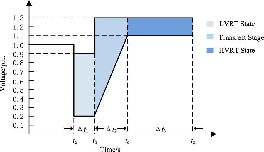
Figure 6: L-HVRT requirements for wind farms.
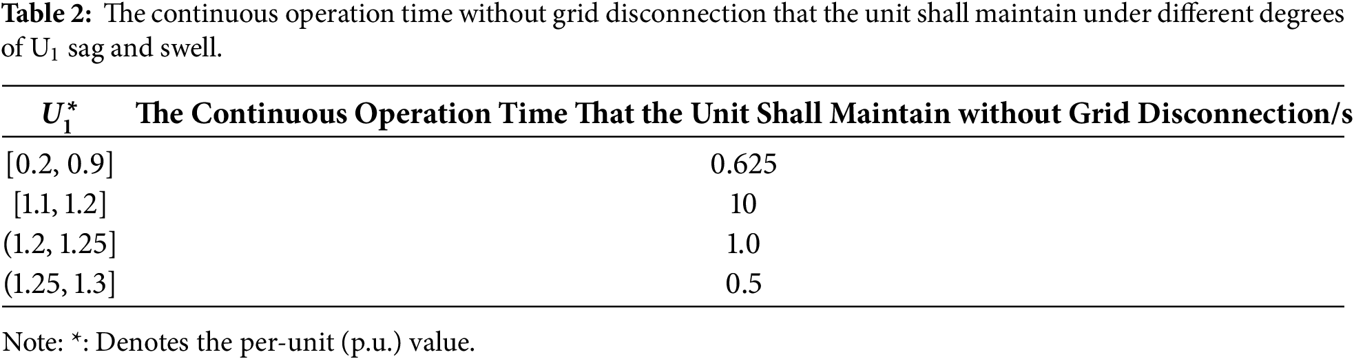
The schematic diagram of the continuous ride-through requirements for wind farms specified in the Chinese national standard is shown in Fig. 6. The continuous ride-through requirements are as follows: (1) When a wind farm transitions rapidly from the low-voltage phase to the high-voltage phase, and the voltage at the wind farm grid connection point falls within the contour line shown in the shaded area, the wind turbines in the wind farm shall maintain continuous operation without grid disconnection; (2) The wind farm shall be able to withstand at least two consecutive low-high voltage ride-through events as shown in Fig. 6; (3) This paper clearly specifies the requirement for Δt2, and the requirements for Δt1 and Δt3 are listed in Table 2.
In this paper, in accordance with the requirements of the Chinese national standard, the simulation analysis is carried out under the most severe conditions, where Δt2 = 0 and the time interval between two L-HVRT events is also set to 0.
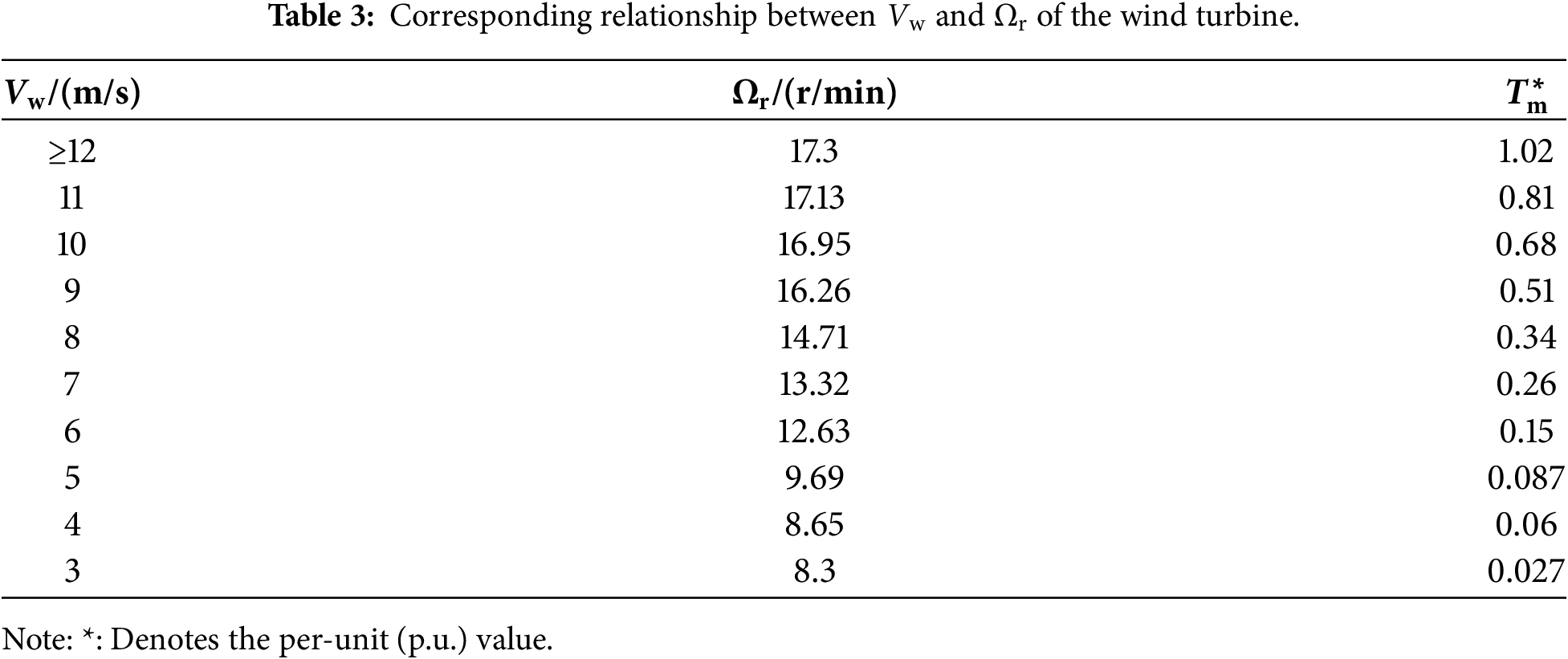
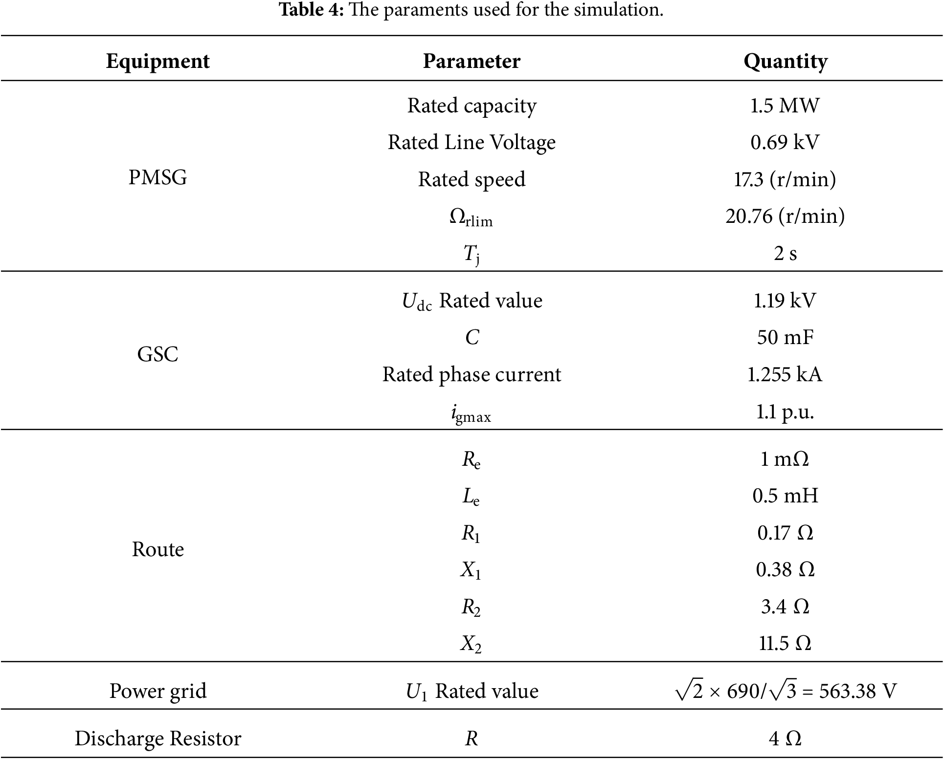
The rated wind speed of the certain model of wind turbine adopted in this paper is 12 m/s. The corresponding relationship between the wind speed Vw and the rotor speed Ωr of the permanent magnet wind turbine used in the simulation is shown in Table 3, and the calculation results of Tm are also included in Table 3. The simulation parameters of the equipment used are listed in Table 4.
In this paper, simulation analysis is carried out for three operating conditions. A voltage sag occurs at t = t0 = 2 s. The degree and duration of the voltage sag and swell are set in accordance with Table 2.
4.3.1 Simulation Results of U1 First Sagging to 0.2 p.u. and Then Swelling to 1.2 p.u. at Vw = 12 m/s
When t = t0 = 2 s, U1 repeats twice the process of first sagging to 0.2 p.u. and then swelling to 1.2 p.u.
(1) Simulation Results of the Traditional Control Strategy
The simulation results of the traditional control strategy are shown in Fig. 7. Before the voltage sag, the wind turbine operates in a steady state, with Ps = 1.0 p.u., Pg = 0.99 p.u., and Udc = 1.0 p.u. During LVRT, Pg is 0.171 p.u., which is consistent with Pgref; during HVRT, Pg is 0.752 p.u., which also aligns with Pgref. During the L-HVRT period, Psref = Popt. When Udc > 1.1 p.u., the braking resistor R is connected. During the LVRT period, the average value of ΔP is 0.83 p.u.; during the HVRT period, the average value of ΔP is 0.06 p.u.
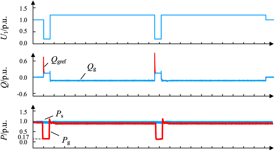
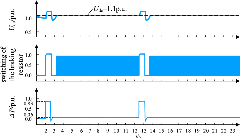
Figure 7: The simulation waveform of the traditional control strategy when U1 drops to 0.2 p.u. and then rises sharply to 1.2 p.u.
(2) Simulation Results of Adopting the Control Strategy Proposed in This Paper
The simulation results of the control strategy proposed in this paper are shown in Fig. 8. During the L-HVRT period, the GSC adjusts the reactive current according to voltage support requirements. The simulation results show that igq = −0.74 p.u. during LVRT and igq = 0.11 p.u. during HVRT, which precisely meets the dynamic reactive current requirements specified in the national standard [21]. Limited by the maximum current capacity constraint of the converter, the available grid-side active power output Pg decreases accordingly, with Pg = 0.171 p.u. during LVRT and Pg = 0.97 p.u. during HVRT, both of which are consistent with the reference value Pgref. At this time, the proposed strategy simultaneously reduces the machine-side output power Ps to maintain power balance, with its reference value Pgref determined by Eq. (10). Since the reduction in Ps leads to an instantaneous deviation between the mechanical torque and the electromagnetic torque, the excess energy is converted into rotor kinetic energy, driving the rotor speed Ωr to rise. When Udc > 1.1 p.u., the braking resistor R is put into operation to assist in consuming the surplus power, and the average values of ΔP during the LVRT and HVRT stages are 0.82 and 0.05 p.u., respectively. Compared with the traditional control strategy, the proposed strategy not only prioritizes the reactive power support requirements of the grid but also effectively suppresses the DC-side overvoltage and mitigates the burden on the braking resistor by utilizing rotor inertia. This ensures that Ωr is consistently kept within the safety limit, thereby achieving continuous fault ride-through for the wind turbine within the standardized fault durations (i.e., operating continuously for 0.625 s under a 0.2 p.u. voltage sag, and for 10 s under a 1.2 p.u. voltage swell).
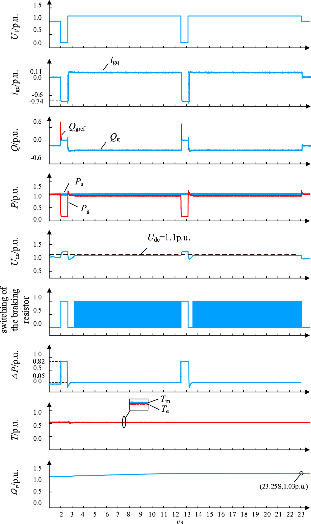
Figure 8: The simulation waveform of the proposed control strategy when U1 drops to 0.2 p.u. and then rises sharply to 1.2 p.u.
(3) Simulation Results of Adopting the Ps = Pg Control Strategy
The simulation results of adopting the Ps = Pg control strategy are shown in Fig. 9. During the LVRT period, Psref = Pgref = 0.169 p.u.; during the HVRT period, Psref = Pgref = 0.751 p.u. When Udc > 1.1 p.u., the braking resistor is connected. During the fault ride-through period, the average value of ΔP = 0. Although the load on the braking resistor is reduced, Tm > Te continues to rise during the fault ride-through process due to Ωr. When t = 2.5 s, Ωr reaches Ωrlim. In actual operation, this will trigger the overspeed protection action, leading to overspeed and grid disconnection of the wind turbine and failure of continuous fault ride-through.
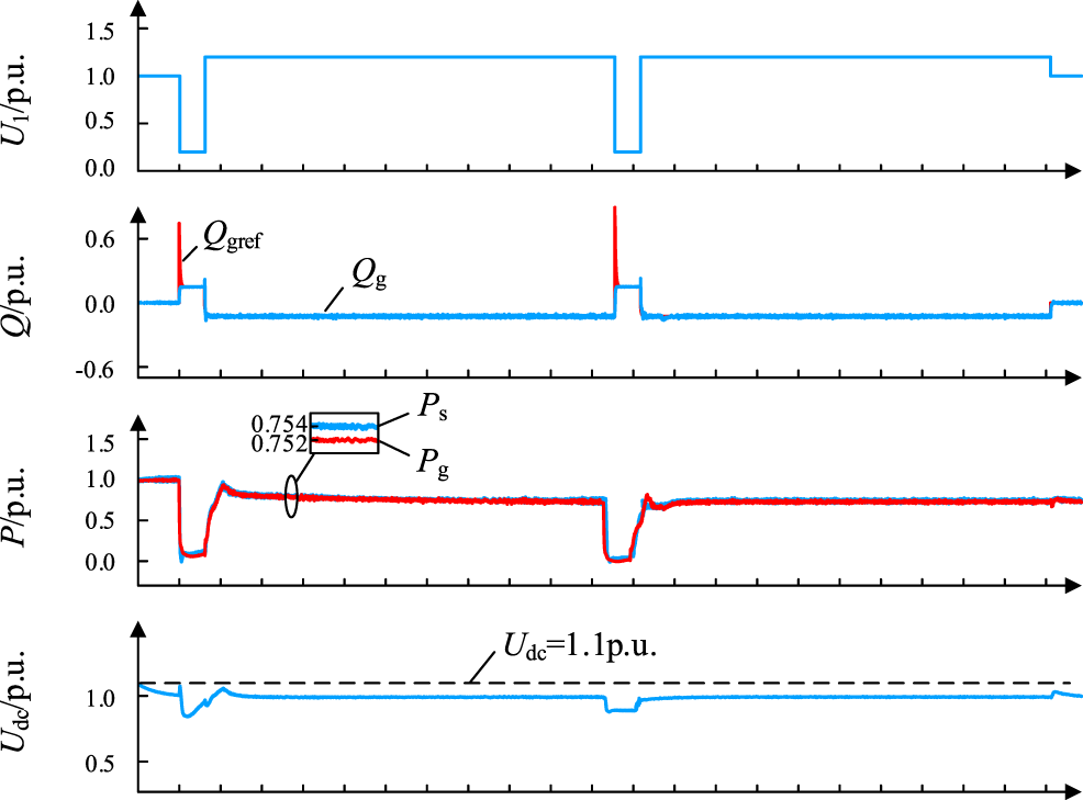
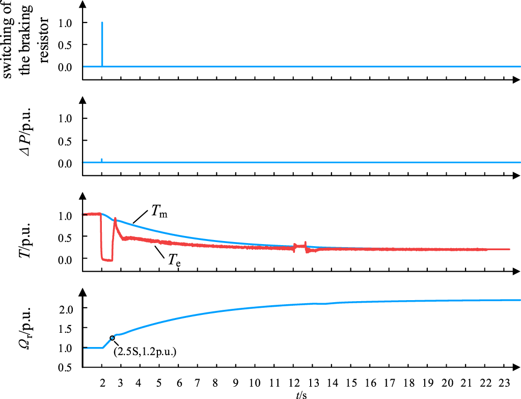
Figure 9: The simulation waveform of the Ps = Pg when U1 drops to 0.2 p.u. and then rises sharply to 1.2 p.u.
In summary, under Operating Condition 1, the traditional control strategy will overload the braking resistor. In contrast, the control strategy proposed in this paper can not only reduce the load on the braking resistor but also prevent the wind turbine from overspeed and grid disconnection, thus achieving successful continuous ride-through.
4.3.2 Simulation Results of U1 First Sagging to 0.2 p.u. and Then Swelling to 1.25 p.u. at Vw = 12 m/s
When t = t0 = 2 s, the process of first sagging to 0.2 p.u. and then swelling to 1.25 p.u. is repeated twice. Under this operating condition, the simulation results of the traditional control strategy are shown in Fig. 10, the simulation results of the control strategy proposed in this paper are shown in Fig. 11, and the simulation results of Ps = Pg are shown in Fig. 12. The comparison of the average value of ΔP and Ωt2 is listed in Table 5.
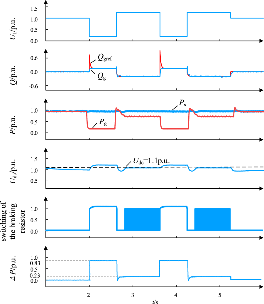
Figure 10: The simulation waveform of the traditional control strategy when U1 drops to 0.2 p.u. and then rises sharply to 1.25 p.u.
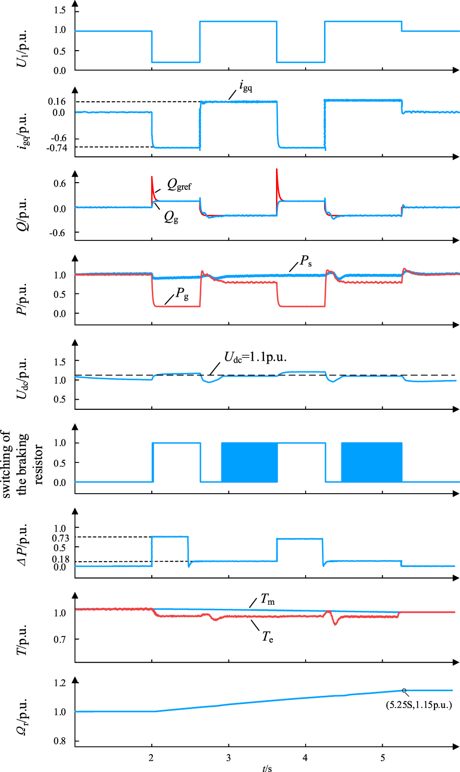
Figure 11: The simulation waveform of the proposed control strategy when U1 drops to 0.2 p.u. and then rises sharply to 1.25 p.u.
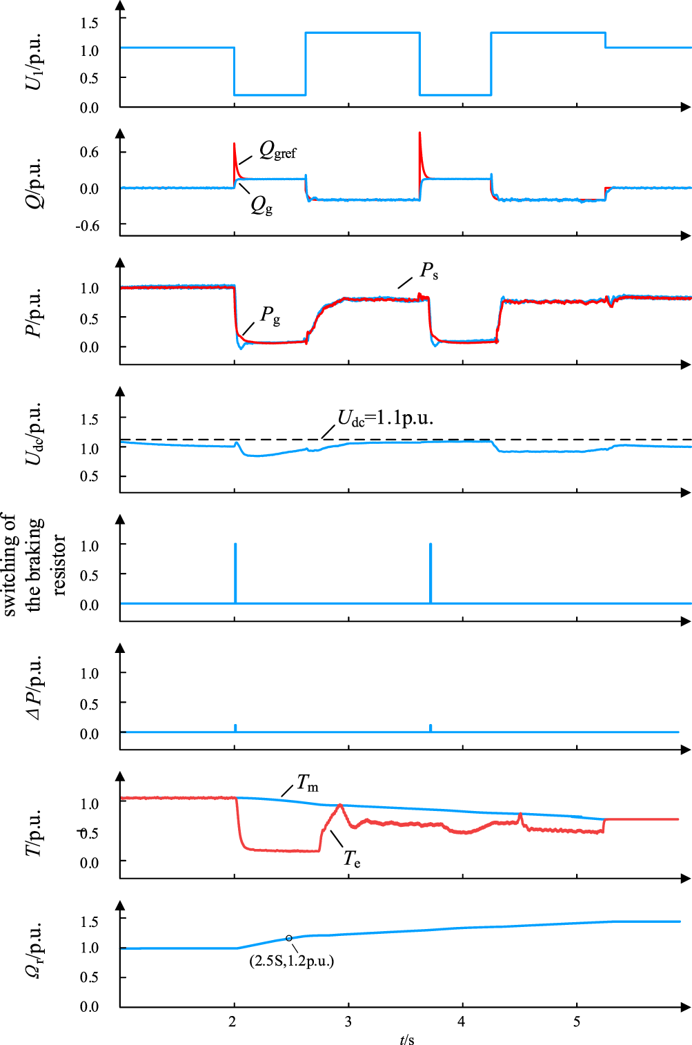
Figure 12: The simulation waveform of Ps = Pg when U1 drops to 0.2 p.u. and then rises sharply to 1.25 p.u.
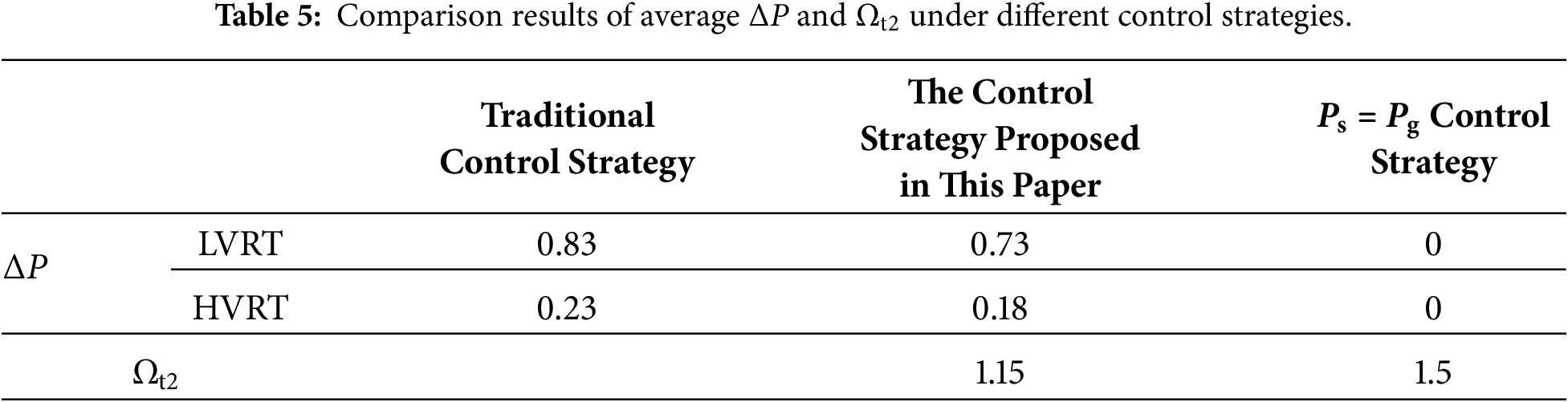
According to the comparative results in Figs. 10–12 and Table 5, under Case 2, the traditional control strategy fails to regulate the machine-side power, forcing the braking resistor R to bear the entire power deviation ΔP. Although the resistor burden can be completely eliminated by significantly reducing Ps (e.g., the Ps = Pg strategy), the total conversion of mechanical energy into rotor kinetic energy causes Ωt2 to reach 1.5 p.u.. This severely exceeds the speed limit Ωrlim = 1.2 p.u., which would trigger overspeed protection and lead to grid disconnection in practical operation.
In contrast, when the proposed control strategy is adopted, the average ΔP burden on the braking resistor R during the LVRT and HVRT stages is reduced to 0.73 and 0.18 p.u., respectively. Furthermore, Ωt2 only rises to 1.15 p.u., which is strictly below the overspeed tripping threshold (Ωrlim = 1.2 p.u.) specified by the national standard. This successfully alleviates the hardware stress while ensuring rotor speed safety, and smoothly completes the 1.0 s high-voltage (1.25 p.u.) ride-through period required by the grid code. When the voltage increases to 1.25 p.u., the grid-side converter must inject a higher level of reactive current to suppress the overvoltage. Due to the physical constraint of the converter’s maximum current capacity igmax, stronger reactive support further compresses the margin for grid-side active current, leading to more severe instantaneous power imbalance. Through the adaptive adjustment of Eq. (10), the proposed strategy converts more surplus energy into rotor kinetic energy in a controlled manner. This not only validates the effectiveness of the strategy under deep fault conditions but also intuitively reveals the positive correlation between reactive support intensity and rotor energy storage demand.
4.3.3 Simulation Results of U1 First Sagging to 0.2 p.u. and Then Swelling to 1.3 p.u. at Vw = 12 m/s
When t = t0 = 2 s, U1 repeats twice the process of first sagging to 0.2 p.u. and then swelling to 1.3 p.u. Under this operating condition, the simulation results of the traditional control strategy are shown in Fig. 13, the simulation results of the control strategy proposed in this paper are shown in Fig. 14, and the simulation results of Ps = Pg are shown in Fig. 15. The comparison of the average value of ΔP and Ωt2 is listed in Table 6.
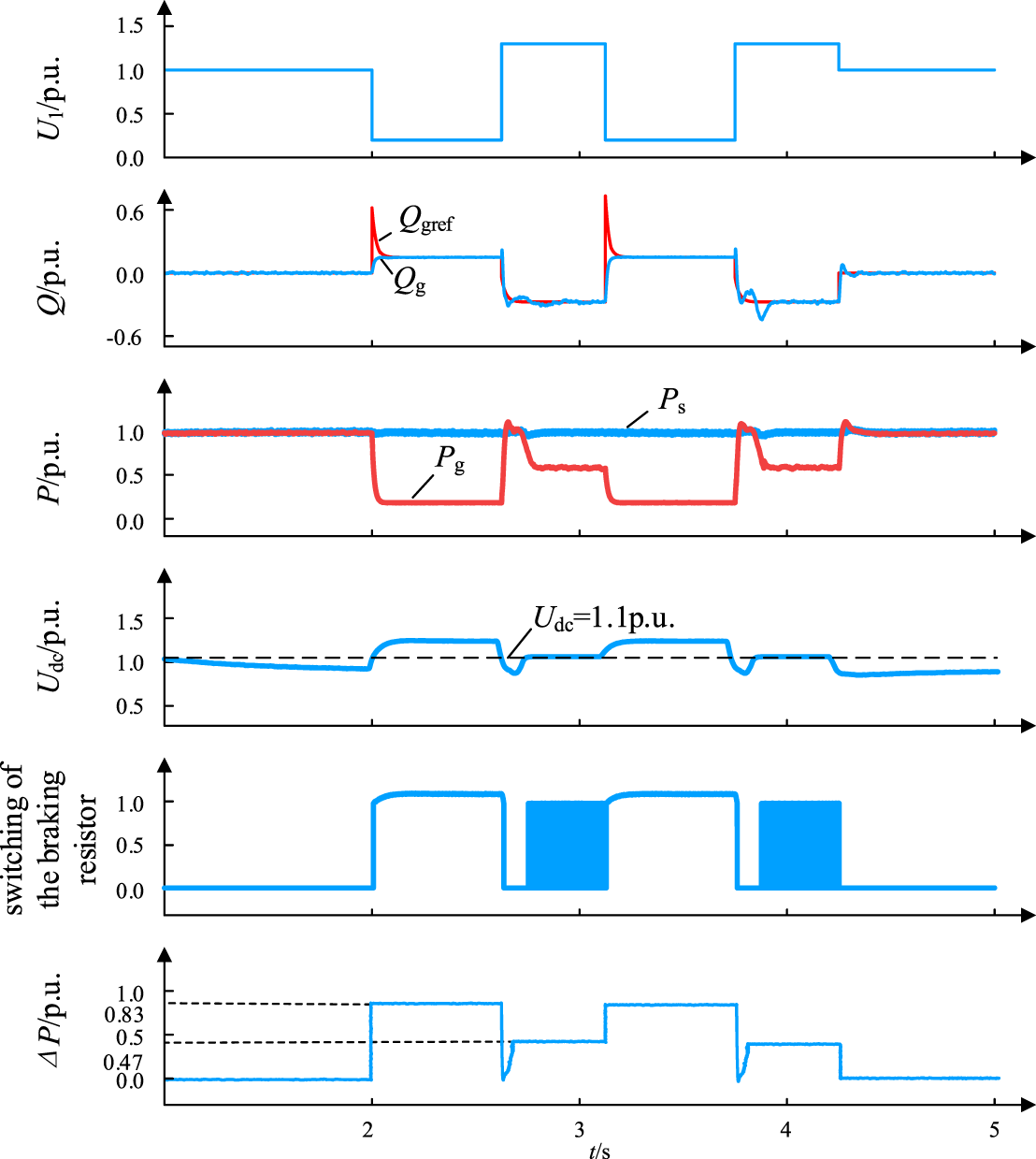
Figure 13: The simulation waveform of the traditional control strategy when U1 drops to 0.2 p.u. and then rises sharply to 1.3 p.u.
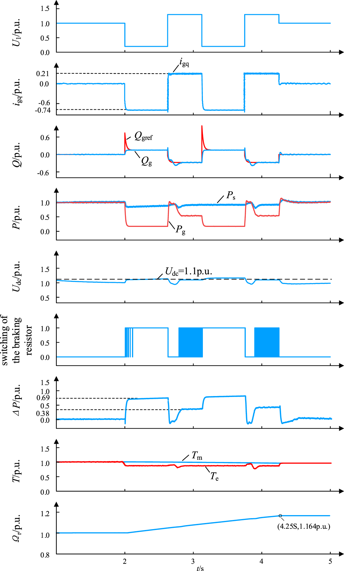
Figure 14: The simulation waveform of the proposed control strategy when U1 drops to 0.2 p.u. and then rises sharply to 1.3 p.u.
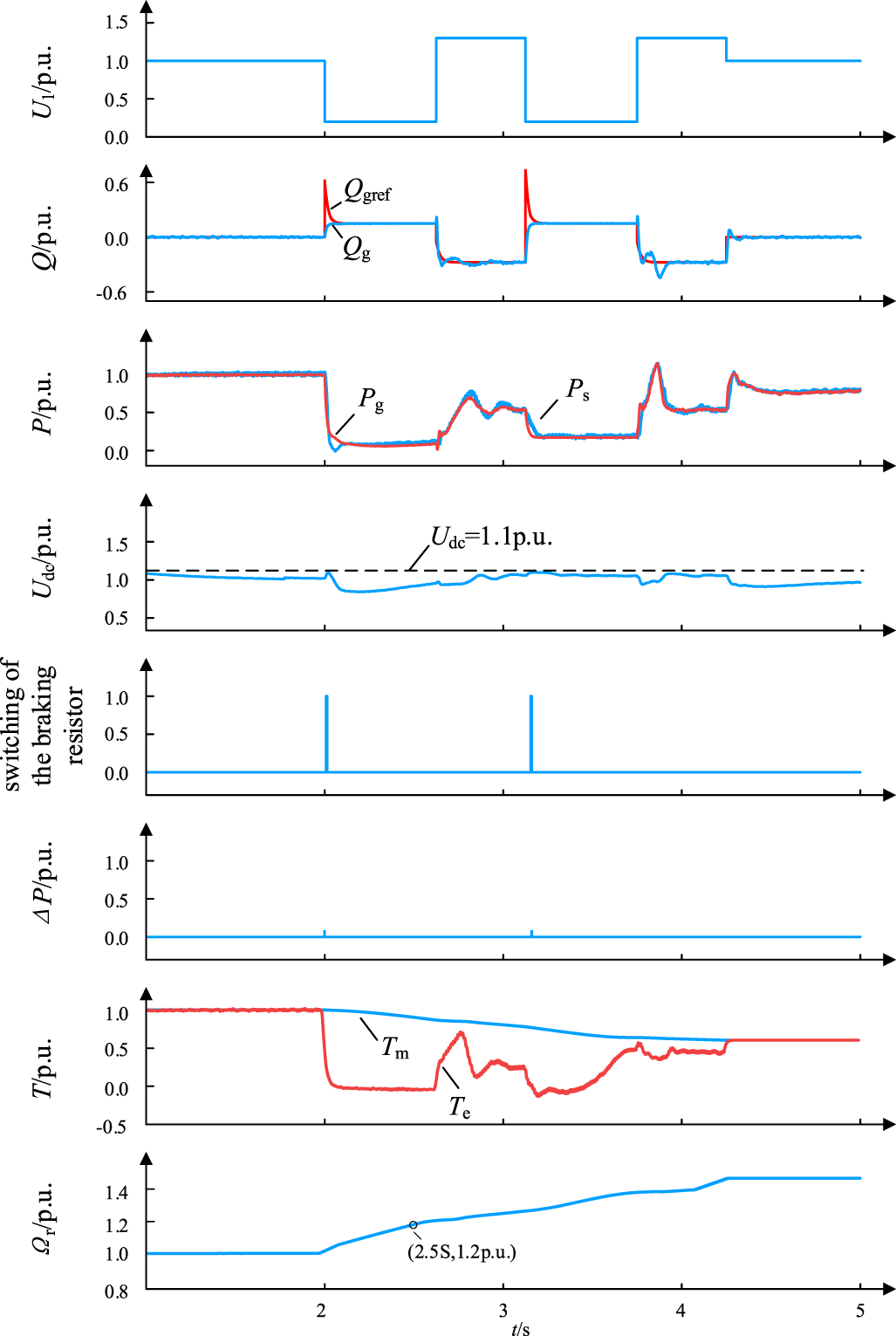
Figure 15: The simulation waveform of the Ps = Pg when U1 drops to 0.2 p.u. and then rises sharply to 1.3 p.u.
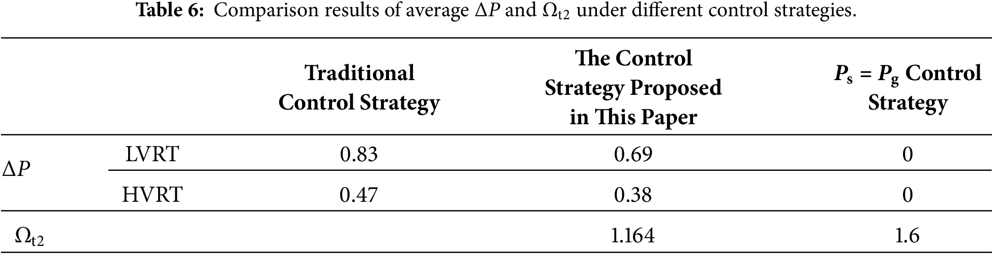
According to the comparative results in Figs. 13–15 and Table 6, under the extreme high-voltage environment of Case 3, the GSC must output the ultimate level of reactive current to respond to grid support requirements, causing the current capacity conflict between reactive support and active power delivery to reach its peak. At this stage, the burden on the braking resistor under the traditional strategy is the heaviest. In contrast, through the adaptive adjustment of Eq. (10), the proposed strategy accurately directs the surplus power toward the rotor shaft system while strictly prioritizing grid reactive power support. As a result, the rotor speed reaches 1.164 p.u. at the end of the ride-through process, consistently remaining within the safety limit (Ωrlim = 1.2 p.u.). This successfully accomplishes the severe 0.5 s high-voltage (1.3 p.u.) ride-through mandated by the grid code.
Finally, based on the aforementioned analysis, the core technical contribution of this strategy in achieving continuous L-HVRT lies in the construction of a “decoupled control” architecture. Under this framework, the GSC is assigned to prioritize responding to grid voltage support by providing reactive power, while the MSC is tasked with independently managing rotor energy by regulating active power. This decoupling mechanism breaks the rigid coupling between grid-side capacity and machine-side control found in traditional strategies, enabling the system to flexibly utilize rotor inertia to ensure speed safety while strictly complying with grid connection codes for reactive support. It is precisely this control logic of “specialized roles and dynamic isolation” that guarantees the overall stability of the system under complex and continuous fault conditions.
During the L-HVRT period, when the traditional control strategy is adopted, the active power reference value Psref output by the MSC remains unchanged, while the grid-side converter (GSC) output power reference value Pgref is set in accordance with the requirements of Chinese national standards. The entire ΔP between the MSC and the GSC is borne by the braking resistor, which increases the load on the braking resistor.
To address the above problems, this paper fully considers reducing the load on the braking resistor on the basis of the original control strategy, and proposes an L-HVRT control strategy based on rotor energy storage. This strategy can not only reduce the load on the braking resistor but also prevent the rotor speed from exceeding the limit. On the PSCAD simulation platform, a continuous ride-through simulation model of a 1.5 MW permanent magnet wind turbine is built in accordance with Chinese national standards, and a comparative simulation analysis is carried out between the control strategy proposed in this paper and the traditional control strategy. The simulation results show that the proposed control strategy can reduce the load on the braking resistor and effectively prevent the rotor speed from exceeding the limit, which verifies the effectiveness of the proposed control strategy.
Acknowledgement: Not applicable.
Funding Statement: The authors received no specific funding.
Author Contributions: The authors confirm contribution to the paper as follows: study conception, task division, content planning, model development, simulation validation, and draff manuscript preparation: Jian Wang, Xiaye Wang; progress, direction oversight, and final manuscript review: Gongqiang Yang; data support, practical validation, and final manuscript review: Jieyan Wang. All authors reviewed and approved the final version of the manuscript.
Availability of Data and Materials: Due to the nature of this research, participants of this study did not agree for their data to be shared publicly, so supporting data is not available.
Ethics Approval: Not applicable.
Conflicts of Interest: The authors declare no conflicts of interest.
References
1. Wu C, Zhang X, Sterling M. Wind power generation variations and aggregations. CSEE J Power Energy Syst. 2022;8(1):17–88. doi:10.17775/cseejpes.2021.03070. [Google Scholar] [CrossRef]
2. You D, Kang S, Seo H, Jang G, Jung S, Yoo Y. LVRT strategy of grid-forming PMSG wind turbine considering transient stability of dc-link voltage. In: Proceedings of the 2023 IEEE Power & Energy Society General Meeting (PESGM); 2023 Jul 16–20; Orlando, FL, USA. p. 1–5. doi:10.1109/pesgm52003.2023.10252360. [Google Scholar] [PubMed] [CrossRef]
3. Zou Z, Yao J. Efficient HVRT scheme of DFIG using a SSFCL-chopper considering grid voltage recovery. IEEE Trans Appl Supercond. 2021;31(8):1–3. doi:10.1109/TASC.2021.3110469. [Google Scholar] [PubMed] [CrossRef]
4. Wu Y, Chang S, Mandal P. Grid-Connected wind power plants: a survey on the integration requirements in modern grid codes. Annu Meet Ind Commer Power Syst Tech Conf. 2019;55(6):5584–93. doi:10.1109/TIA.2019.2934081. [Google Scholar] [PubMed] [CrossRef]
5. Xu B, Ren J, Zheng Z, Hu W, Xie Q, Song D. A LVRT method for PMSG-Based wind turbine to suppress the post-fault overvoltage using SMES. In: Proceedings of the 2023 IEEE International Conference on Applied Superconductivity and Electromagnetic Devices (ASEMD); 2023 Oct 27–29; Tianjin, China. p. 1–2. doi:10.1109/ASEMD59061.2023.10368634. [Google Scholar] [PubMed] [CrossRef]
6. Huang C, Xiao X, Zheng Z, Li C. Improving LVRT capability and transient stability of mw-class PMSG with a inserted R-SFCL under grid fault. In: Proceedings of the 2018 IEEE International Conference on Applied Superconductivity and Electromagnetic Devices (ASEMD); 2018 Apr 15–18; Tianjin, China. p. 1–2. doi:10.1109/ASEMD.2018.8558929. [Google Scholar] [PubMed] [CrossRef]
7. Kheibargir D, Zeinali R, Aliabadi SM. Augmentation of fault ride-through capability of PMSG in a wind power plant using resistive SFCL and a new reactive current injection controller. In: Proceedings of the 2019 International Power System Conference (PSC); 2019 Dec 9–11; Tehran, Iran. p. 623–31. doi:10.1109/PSC49016.2019.9081566. [Google Scholar] [PubMed] [CrossRef]
8. Liu G, Zhang C, Wang S. An integrated control strategy of PMSG-based wind turbine generation system to improve its fault ride-through capability by using an energy storage device. In: Proceedings of the International Conference on Renewable Power Generation (RPG 2015); 2015 Oct 17–18; Beijing, China. doi:10.1049/cp.2015.0309. [Google Scholar] [CrossRef]
9. Ji T, Li X, Liu K, Zhang M. Performance analysis and research on LVRT of PMSG wind power systems with SDBR. In: Proceedings of the 33rd Chinese Control Conference; 2014 Jul 28–30; Nanjing, China. p. 6953–8. doi:10.1109/ChiCC.2014.6896146. [Google Scholar] [PubMed] [CrossRef]
10. Dey P, Datta M, Fernando N, Senjyu T. A method to reduce DC-link overvoltage of PMSG based WECS during LVRT. In: Proceedings of the 2016 IEEE Region 10 Conference (TENCON); 2016 Nov 22–25; Singapore. p. 1894–9. doi:10.1109/TENCON.2016.7848351. [Google Scholar] [PubMed] [CrossRef]
11. Dey P, Datta M, Fernando N. Comparisons of PI and PR current controllers based flux weakening to limit DC-link capacitor overvoltage in PMSG based wind energy system. In: Proceedings of the 2016 IEEE Innovative Smart Grid Technologies—Asia (ISGT-Asia); 2016 Nov 28–Dec 1; Melbourne, VIC, Australia. p. 29–34. doi:10.1109/ISGT-Asia.2016.7796356. [Google Scholar] [PubMed] [CrossRef]
12. Zhang Z, Zhang Z, Liu X, Hao Q, Zhang Z. LVRT control of back-to-back power converter PMSG wind turbine systems: an FPGA based hardware-in-the-loop solution. In: Proceedings of the 2019 IEEE Energy Conversion Congress and Exposition (ECCE); 2019 Sep 29–Oct 3; Baltimore, MD, USA. doi:10.1109/ECCE.2019.8913004. [Google Scholar] [PubMed] [CrossRef]
13. Abbes M, Allagui M, Hasnaoui OKB. An aggregate model of PMSG-based, grid connected wind farm: investigation of LVRT capabilities. In: Proceedings of the IREC2015 The Sixth International Renewable Energy Congress; 2015 March 24–26; Sousse, Tunisia. p. 1–6. doi:10.1109/IREC.2015.7110976. [Google Scholar] [PubMed] [CrossRef]
14. Liu C, He J, Xie Z. High voltage ride-through of grid-side converter for PMSG based directly driven wind turbines. In: Proceedings of the 2016 35th Chinese Control Conference (CCC); 2016 Jul 27–29; Chengdu, China. p. 8528–32. doi:10.1109/ChiCC.2016.7554719. [Google Scholar] [PubMed] [CrossRef]
15. Liu P, Gao X, Ding L. The influence of the grid overvoltage on fully rated converter wind turbine and an HVRT control strategy based on reactive Current. In: Proceedings of the 2019 IEEE 8th International Conference on Advanced Power System Automation and Protection (APAP); 2019 Oct 21–24; Xi’an, China. p. 411–5. doi:10.1109/APAP47170.2019.9224759. [Google Scholar] [PubMed] [CrossRef]
16. Wang DS, Yan XW, Jia JX. High and low voltage continuous fault ride-through strategy for permanent magnet direct-drive fans based on virtual synchronous technology. J Electr Eng. 2022;42(6):2164–75. (In Chinese). doi:10.1109/ei259745.2023.10512526. [Google Scholar] [PubMed] [CrossRef]
17. Tian SX, Chen WH, Wang PP. Continuous voltage ride-through control strategy for PMSG-based wind power systems with variable reactive current proportional coefficients. J Electr Eng. 2024;44(19):7671–84. (In Chinese). doi:10.13334/j.0258-8013.pcsee.230429. [Google Scholar] [CrossRef]
18. Chen XJ, Guang C, Jiang QY. Adaptive coordinated control of fault voltage ride-through for wind turbines based on energy storage. Autom Electr Power Syst. 2023;47(7):158–65. (In Chinese). doi:10.1109/repe66317.2025.11341108. [Google Scholar] [PubMed] [CrossRef]
19. Fu J, Yan X, Wang D, Liu H, Cheng D. L/HVRT scheme of offshore permanent magnet synchronous wind turbine, Online. In: Proceedings of the 18th International Conference on AC and DC Power Transmission; 2022 Jul 2–3; Online. p. 1356–63. doi:10.1049/icp.2022.1412. [Google Scholar] [CrossRef]
20. Yuan L, Meng K, Huang J, Dong Z, Zhang W. Coordinated LVRT and HVRT control scheme for PMSG-based wind farm. In: Proceedings of the 2019 29th Australasian Universities Power Engineering Conference (AUPEC); 2019 Nov 26; Nadi, Fiji. p. 1–6. doi:10.1109/AUPEC48547.2019.211815. [Google Scholar] [PubMed] [CrossRef]
21. GB/T 19963.1-2021. Technical specification for connecting wind farm to power system-part 1: onshore wind power. Beijing, China: Standardization Administration of China; 2021. [Google Scholar]
Cite This Article
 Copyright © 2026 The Author(s). Published by Tech Science Press.
This work is licensed under a Creative Commons Attribution 4.0 International License , which permits unrestricted use, distribution, and reproduction in any medium, provided the original work is properly cited.
 Downloads
 Citation Tools
